


 MITSUBISHI ELECTRIC
Motion Controllers
Programming Manual
Common
Q173DCPU
Q172DCPU
01 01 2008 B(NA)-0300134 Version A
 MITSUBISHI ELECTRIC INDUSTRIAL AUTOMATION

 SAFETY PRECAUTIONS
(Please read these instructions before using this equipment.)
Before using this product, please read this manual and the relevant manuals introduced in this manual carefully and pay full attention to safety to handle the product correctly.
These precautions apply only to this product. Refer to the Q173DCPU/Q172DCPU Users manual for a description of the Motion controller safety precautions.
In this manual, the safety instructions are ranked as "DANGER" and "CAUTION".

 DANGER

 CAUTION
Indicates that incorrect handling may cause hazardous conditions, resulting in death or severe injury.
Indicates that incorrect handling may cause hazardous conditions, resulting in medium or slight personal injury or physical damage.
Depending on circumstances, procedures indicated by  CAUTION may also be linked to serious results.
In any case, it is important to follow the directions for usage.
Please save this manual to make it accessible when required and always forward it to the end user.
A - 1

For Safe Operations
1. Prevention of electric shocks
 DANGER
 Never open the front case or terminal covers while the power is ON or the unit is running, as this may lead to electric shocks.
 Never run the unit with the front case or terminal cover removed. The high voltage terminal and charged sections will be exposed and may lead to electric shocks.
 Never open the front case or terminal cover at times other than wiring work or periodic inspections even if the power is OFF. The insides of the Motion controller and servo amplifier are charged and may lead to electric shocks.
 Completely turn off the externally supplied power used in the system before mounting or removing the module, performing wiring work, or inspections. Failing to do so may lead to electric shocks.
 When performing wiring work or inspections, turn the power OFF, wait at least ten minutes, and then check the voltage with a tester, etc.. Failing to do so may lead to electric shocks.
 Be sure to ground the Motion controller, servo amplifier and servomotor. (Ground resistance : 100
  or less) Do not ground commonly with other devices.
 The wiring work and inspections must be done by a qualified technician.
 Wire the units after installing the Motion controller, servo amplifier and servomotor. Failing to do so may lead to electric shocks or damage.
 Never operate the switches with wet hands, as this may lead to electric shocks.
 Do not damage, apply excessive stress, place heavy things on or sandwich the cables, as this may lead to electric shocks.
 Do not touch the Motion controller, servo amplifier or servomotor terminal blocks while the power is ON, as this may lead to electric shocks.
 Do not touch the built-in power supply, built-in grounding or signal wires of the Motion controller and servo amplifier, as this may lead to electric shocks.
2. For fire prevention
 CAUTION
 Install the Motion controller, servo amplifier, servomotor and regenerative resistor on incombustible. Installing them directly or close to combustibles will lead to fire.
 If a fault occurs in the Motion controller or servo amplifier, shut the power OFF at the servo amplifier’s power source. If a large current continues to flow, fire may occur.
 When using a regenerative resistor, shut the power OFF with an error signal. The regenerative resistor may abnormally overheat due to a fault in the regenerative transistor, etc., and may lead to fire.
 Always take heat measures such as flame proofing for the inside of the control panel where the servo amplifier or regenerative resistor is installed and for the wires used. Failing to do so may lead to fire.
 Do not damage, apply excessive stress, place heavy things on or sandwich the cables, as this may lead to fire.
A - 2

3. For injury prevention
 CAUTION
 Do not apply a voltage other than that specified in the instruction manual on any terminal. Doing so may lead to destruction or damage.
 Do not mistake the terminal connections, as this may lead to destruction or damage.
 Do not mistake the polarity ( + / - ), as this may lead to destruction or damage.
 Do not touch the heat radiating fins of controller or servo amplifier, regenerative resistor and servomotor, etc., while the power is ON and for a short time after the power is turned OFF. In this timing, these parts become very hot and may lead to burns.
 Always turn the power OFF before touching the servomotor shaft or coupled machines, as these parts may lead to injuries.
 Do not go near the machine during test operations or during operations such as teaching. Doing so may lead to injuries.
4. Various precautions
Strictly observe the following precautions.
Mistaken handling of the unit may lead to faults, injuries or electric shocks.
(1) System structure
 CAUTION
 Always install a leakage breaker on the Motion controller and servo amplifier power source.
 If installation of an electromagnetic contactor for power shut off during an error, etc., is specified in the instruction manual for the servo amplifier, etc., always install the electromagnetic contactor.
 Install the emergency stop circuit externally so that the operation can be stopped immediately and the power shut off.
 Use the Motion controller, servo amplifier, servomotor and regenerative resistor with the correct combinations listed in the instruction manual. Other combinations may lead to fire or faults.
 Use the CPU module, base unit and motion module with the correct combinations listed in the instruction manual. Other combinations may lead to faults.
 If safety standards (ex., robot safety rules, etc.,) apply to the system using the Motion controller, servo amplifier and servomotor, make sure that the safety standards are satisfied.
 Construct a safety circuit externally of the Motion controller or servo amplifier if the abnormal operation of the Motion controller or servo amplifier differ from the safety directive operation in the system.
 In systems where coasting of the servomotor will be a problem during the forced stop, emergency stop, servo OFF or power supply OFF, use dynamic brakes.
 Make sure that the system considers the coasting amount even when using dynamic brakes.
  In systems where perpendicular shaft dropping may be a problem during the forced stop,
emergency stop, servo OFF or power supply OFF, use both dynamic brakes and electromagnetic brakes.
A - 3

 CAUTION
 The dynamic brakes must be used only on errors that cause the forced stop, emergency stop, or servo OFF. These brakes must not be used for normal braking.
 The brakes (electromagnetic brakes) assembled into the servomotor are for holding applications, and must not be used for normal braking.
 The system must have a mechanical allowance so that the machine itself can stop even if the stroke limits switch is passed through at the max. speed.
 Use wires and cables that have a wire diameter, heat resistance and bending resistance compatible with the system.
 Use wires and cables within the length of the range described in the instruction manual.
 The ratings and characteristics of the parts (other than Motion controller, servo amplifier and servomotor) used in a system must be compatible with the Motion controller, servo amplifier and servomotor.
 Install a cover on the shaft so that the rotary parts of the servomotor are not touched during operation.
 There may be some cases where holding by the electromagnetic brakes is not possible due to the life or mechanical structure (when the ball screw and servomotor are connected with a timing belt, etc.). Install a stopping device to ensure safety on the machine side.
(2) Parameter settings and programming
 CAUTION
 Set the parameter values to those that are compatible with the Motion controller, servo amplifier, servomotor and regenerative resistor model and the system application. The protective functions may not function if the settings are incorrect.
 The regenerative resistor model and capacity parameters must be set to values that conform to the operation mode, servo amplifier and servo power supply module. The protective functions may not function if the settings are incorrect.
 Set the mechanical brake output and dynamic brake output validity parameters to values that are compatible with the system application. The protective functions may not function if the settings are incorrect.
 Set the stroke limit input validity parameter to a value that is compatible with the system application. The protective functions may not function if the setting is incorrect.
 Set the servomotor encoder type (increment, absolute position type, etc.) parameter to a value that is compatible with the system application. The protective functions may not function if the setting is incorrect.
 Set the servomotor capacity and type (standard, low-inertia, flat, etc.) parameter to values that are compatible with the system application. The protective functions may not function if the settings are incorrect.
 Set the servo amplifier capacity and type parameters to values that are compatible with the system application. The protective functions may not function if the settings are incorrect.
A - 4

 CAUTION
 Use the program commands for the program with the conditions specified in the instruction manual.
 Set the sequence function program capacity setting, device capacity, latch validity range, I/O assignment setting, and validity of continuous operation during error detection to values that are compatible with the system application. The protective functions may not function if the settings are incorrect.
 Some devices used in the program have fixed applications, so use these with the conditions specified in the instruction manual.
 The input devices and data registers assigned to the link will hold the data previous to when communication is terminated by an error, etc. Thus, an error correspondence interlock program specified in the instruction manual must be used.
 Use the interlock program specified in the intelligent function module's instruction manual for the program corresponding to the intelligent function module.
(3) Transportation and installation
 CAUTION
 Transport the product with the correct method according to the mass.
 Use the servomotor suspension bolts only for the transportation of the servomotor. Do not transport the servomotor with machine installed on it.
 Do not stack products past the limit.
 When transporting the Motion controller or servo amplifier, never hold the connected wires or cables.
 When transporting the servomotor, never hold the cables, shaft or detector.
 When transporting the Motion controller or servo amplifier, never hold the front case as it may fall off.
 When transporting, installing or removing the Motion controller or servo amplifier, never hold the edges.
 Install the unit according to the instruction manual in a place where the mass can be withstood.
 Do not get on or place heavy objects on the product.
 Always observe the installation direction.
 Keep the designated clearance between the Motion controller or servo amplifier and control panel inner surface or the Motion controller and servo amplifier, Motion controller or servo amplifier and other devices.
 Do not install or operate Motion controller, servo amplifiers or servomotors that are damaged or that have missing parts.
 Do not block the intake/outtake ports of the Motion controller, servo amplifier and servomotor with cooling fan.
 Do not allow conductive matter such as screw or cutting chips or combustible matter such as oil enter the Motion controller, servo amplifier or servomotor.
A - 5

 CAUTION
 The Motion controller, servo amplifier and servomotor are precision machines, so do not drop or apply strong impacts on them.
 Securely fix the Motion controller, servo amplifier and servomotor to the machine according to the instruction manual. If the fixing is insufficient, these may come off during operation.
 Always install the servomotor with reduction gears in the designated direction. Failing to do so may lead to oil leaks.
 Store and use the unit in the following environmental conditions.
Environment |
Conditions |
|
||
|
|
|
||
Motion controller/Servo amplifier |
|
Servomotor |
||
|
|
|||
Ambient |
According to each instruction manual. |
|
0°C to +40°C (With no freezing) |
|
temperature |
|
(32°F to +104°F) |
||
|
|
|||
Ambient humidity |
According to each instruction manual. |
|
80% RH or less |
|
|
(With no dew condensation) |
|||
|
|
|
||
Storage |
According to each instruction manual. |
|
-20°C to +65°C |
|
temperature |
|
(-4°F to +149°F) |
||
|
|
|||
Atmosphere |
Indoors (where not subject to direct sunlight). |
|||
No corrosive gases, flammable gases, oil mist or dust must exist |
||||
|
||||
Altitude |
1000m (3280.84ft.) or less above sea level |
|||
Vibration |
According to each instruction manual |
|||
 When coupling with the synchronous encoder or servomotor shaft end, do not apply impact such as by hitting with a hammer. Doing so may lead to detector damage.
 Do not apply a load larger than the tolerable load onto the synchronous encoder and servomotor shaft. Doing so may lead to shaft breakage.
 When not using the module for a long time, disconnect the power line from the Motion controller or servo amplifier.
 Place the Motion controller and servo amplifier in static electricity preventing vinyl bags and store.
  When storing for a long time, please contact with our sales representative.
Also, execute a trial operation.
A - 6
(4) Wiring
 CAUTION
 Correctly and securely wire the wires. Reconfirm the connections for mistakes and the terminal screws for tightness after wiring. Failing to do so may lead to run away of the servomotor.
 After wiring, install the protective covers such as the terminal covers to the original positions.
  Do not install a phase advancing capacitor, surge absorber or radio noise filter (option FR-BIF)
on the output side of the servo amplifier. |
|
|
|
Correctly connect the output side (terminal U, V, W). Incorrect connections will lead the |
|
||
servomotor to operate abnormally. |
|
|
|
Do not connect a commercial power supply to the servomotor, as this may lead to trouble. |
|
||
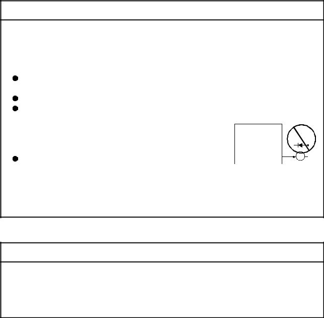
Do not mistake the direction of the surge absorbing diode |
|
|
|
installed on the DC relay for the control signal output of brake |
Servo amplifier |
|
|
signals, etc. Incorrect installation may lead to signals not being |
VIN |
|
|
output when trouble occurs or the protective functions not |
(24VDC) |
|
|
|
|
||
functioning. |
Control output |
RA |
|
Do not connect or disconnect the connection cables between |
signal |
||
|
|||
each unit, the encoder cable or PLC expansion cable while the power is ON.
 Securely tighten the cable connector fixing screws and fixing mechanisms. Insufficient fixing may lead to the cables combing off during operation.
 Do not bundle the power line or cables.
(5) Trial operation and adjustment
 CAUTION
 Confirm and adjust the program and each parameter before operation. Unpredictable movements may occur depending on the machine.
 Extreme adjustments and changes may lead to unstable operation, so never make them.
  When using the absolute position system function, on starting up, and when the Motion controller or absolute value motor has been replaced, always perform a home position return.
A - 7

(6) Usage methods
 CAUTION
 Immediately turn OFF the power if smoke, abnormal sounds or odors are emitted from the Motion controller, servo amplifier or servomotor.
 Always execute a test operation before starting actual operations after the program or parameters have been changed or after maintenance and inspection.
 Do not attempt to disassemble and repair the units excluding a qualified technician whom our company recognized.
 Do not make any modifications to the unit.
 Keep the effect or electromagnetic obstacles to a minimum by installing a noise filter or by using wire shields, etc. Electromagnetic obstacles may affect the electronic devices used near the Motion controller or servo amplifier.
 When using the CE Mark-compliant equipment, refer to the "EMC Installation Guidelines" (data number IB(NA)-67339) for the Motion controllers and refer to the corresponding EMC guideline information for the servo amplifiers, inverters and other equipment.
 Use the units with the following conditions.
Item |
|
|
|
|
Conditions |
|
|
|
|
|
Q61P-A1 |
|
Q61P-A2 |
|
Q61P |
Q62P |
Q63P |
|
Q64P |
|
|
|
|
|
|
|
||||||
|
100 to 120VAC |
+10% |
200 to 240VAC |
+10% |
100 to 240VAC +10% |
24VDC |
+30% |
100 to 120VAC +10% |
/ |
|
|
|
-15% |
|
-15% |
|
-15% |
|
-35% |
-15% |
|
Input power |
|
|
|
|
|
|
|
|
200 to 240VAC -+10%15% |
|
|
(85 to 132VAC) |
(170 to 264VAC) |
(85 to 264VAC) |
(15.6 to 31.2VDC) |
(85 to 132VAC/ |
|
||||
|
|
|
|
|
|
|
|
|
170 to 264VAC) |
|
Input frequency |
|
|
|
|
50/60Hz ±5% |
|
|
|
|
|
Tolerable |
|
|
|
|
|
|
|
|
|
|
momentary |
|
|
|
|
20ms or less |
|
|
|
|
|
power failure |
|
|
|
|
|
|
|
|
|
|
A - 8
(7) Corrective actions for errors
 CAUTION
 If an error occurs in the self diagnosis of the Motion controller or servo amplifier, confirm the check details according to the instruction manual, and restore the operation.
 If a dangerous state is predicted in case of a power failure or product failure, use a servomotor with electromagnetic brakes or install a brake mechanism externally.
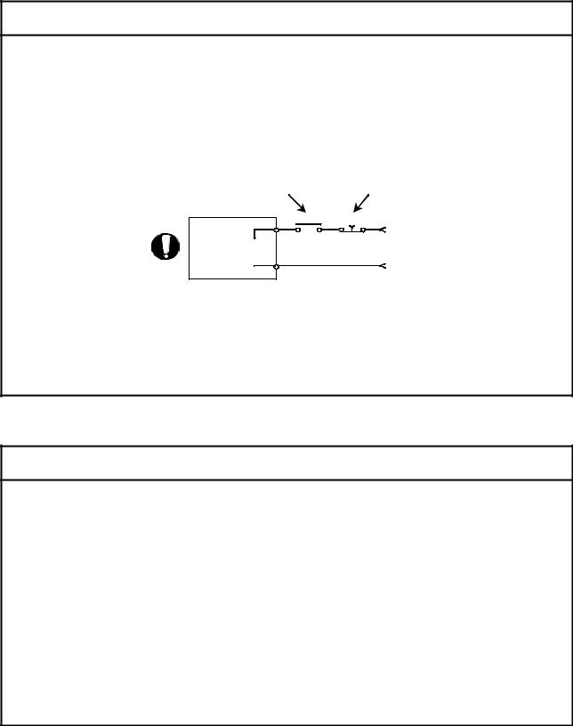
 Use a double circuit construction so that the electromagnetic brake operation circuit can be operated by emergency stop signals set externally.
Shut off with servo ON signal OFF, alarm, electromagnetic brake signal.
Servomotor
RA1
Electro-  magnetic
  brakes
Shut off with the emergency stop signal(EMG).
EMG
24VDC
 If an error occurs, remove the cause, secure the safety and then resume operation after alarm release.
 The unit may suddenly resume operation after a power failure is restored, so do not go near the machine. (Design the machine so that personal safety can be ensured even if the machine restarts suddenly.)
(8) Maintenance, inspection and part replacement
 CAUTION
 Perform the daily and periodic inspections according to the instruction manual.
 Perform maintenance and inspection after backing up the program and parameters for the Motion controller and servo amplifier.
 Do not place fingers or hands in the clearance when opening or closing any opening.
 Periodically replace consumable parts such as batteries according to the instruction manual.
 Do not touch the lead sections such as ICs or the connector contacts.
 Before touching the module, always touch grounded metal, etc. to discharge static electricity from human body. Failure to do so may cause the module to fail or malfunction.
 Do not directly touch the module's conductive parts and electronic components. Touching them could cause an operation failure or give damage to the module.
 Do not place the Motion controller or servo amplifier on metal that may cause a power leakage or wood, plastic or vinyl that may cause static electricity buildup.
 Do not perform a megger test (insulation resistance measurement) during inspection.
A - 9
 CAUTION
 When replacing the Motion controller or servo amplifier, always set the new module settings correctly.
 When the Motion controller or absolute value motor has been replaced, carry out a home position return operation using one of the following methods, otherwise position displacement could occur.
1)After writing the servo data to the Motion controller using programming software, switch on the power again, then perform a home position return operation.
2)Using the backup function of the programming software, load the data backed up before
replacement.
 After maintenance and inspections are completed, confirm that the position detection of the absolute position detector function is correct.
 Do not drop or impact the battery installed to the module.
Doing so may damage the battery, causing battery liquid to leak in the battery. Do not use the dropped or impacted battery, but dispose of it.
 Do not short circuit, charge, overheat, incinerate or disassemble the batteries.
 The electrolytic capacitor will generate gas during a fault, so do not place your face near the Motion controller or servo amplifier.
 The electrolytic capacitor and fan will deteriorate. Periodically replace these to prevent secondary damage from faults. Replacements can be made by our sales representative.
(9) About processing of waste
When you discard Motion controller, servo amplifier, a battery (primary battery) and other option articles, please follow the law of each country (area).
 CAUTION
 This product is not designed or manufactured to be used in equipment or systems in situations that can affect or endanger human life.
 When considering this product for operation in special applications such as machinery or systems used in passenger transportation, medical, aerospace, atomic power, electric power, or submarine repeating applications, please contact your nearest Mitsubishi sales representative.
  Although this product was manufactured under conditions of strict quality control, you are strongly advised to install safety devices to forestall serious accidents when it is used in facilities where a breakdown in the product is likely to cause a serious accident.
(10) General cautions
 CAUTION
 All drawings provided in the instruction manual show the state with the covers and safety partitions removed to explain detailed sections. When operating the product, always return the covers and partitions to the designated positions, and operate according to the instruction manual.
A - 10

REVISIONS
|
|
The manual number is given on the bottom left of the back cover. |
Print Date |
Manual Number |
Revision |
Jan., 2008 |
IB(NA)-0300134-A |
First edition |
|
|
|
Japanese Manual Number IB(NA)-0300126
This manual confers no industrial property rights or any rights of any other kind, nor does it confer any patent licenses. Mitsubishi Electric Corporation cannot be held responsible for any problems involving industrial property rights which may occur as a result of using the contents noted in this manual.
© 2008 MITSUBISHI ELECTRIC CORPORATION
A - 11
INTRODUCTION
Thank you for choosing the Mitsubishi Motion controller Q173DCPU/Q172DCPU.
Before using the equipment, please read this manual carefully to develop full familiarity with the functions and performance of the Motion controller you have purchased, so as to ensure correct use.
CONTENTS |
|
|
Safety Precautions .................................................................................................................................. |
A- |
1 |
Revisions................................................................................................................................................. |
A-11 |
|
Contents.................................................................................................................................................. |
A-12 |
|
About Manuals ........................................................................................................................................ |
A-14 |
|
|
|
|
1. OVERVIEW |
1- 1 to 1-20 |
|
1.1 Overview ........................................................................................................................................... |
1- |
1 |
1.2 Features ............................................................................................................................................ |
1- |
3 |
1.2.1 Features of Motion CPU ................................................................................................................... |
1- 3 |
|
1.2.2 Basic specifications of Q173DCPU/Q172DCPU ............................................................................. |
1- 5 |
|
1.3 Hardware Configuration .................................................................................................................... |
1- |
8 |
1.3.1 Motion system configuration ............................................................................................................. |
1- |
8 |
1.3.2 Q173DCPU System overall configuration........................................................................................ |
1-10 |
|
1.3.3 Q172DCPU System overall configuration........................................................................................ |
1-12 |
|
1.3.4 Software packages............................................................................................................................ |
1-14 |
|
1.3.5 Restrictions on motion systems........................................................................................................ |
1-17 |
|
|
|
|
2. MULTIPLE CPU SYSTEM |
2- 1 to 2-32 |
|
2.1 Multiple CPU System ........................................................................................................................ |
2- 1 |
|
2.1.1 Overview............................................................................................................................................ |
2- |
1 |
2.1.2 Installation position of CPU module.................................................................................................. |
2- |
2 |
2.1.3 Precautions for using I/O modules and intelligent function modules............................................... |
2- |
3 |
2.1.4 Modules subject to installation restrictions ....................................................................................... |
2- |
4 |
2.1.5 How to reset the Multiple CPU system............................................................................................. |
2- 5 |
|
2.1.6 Operation for CPU module stop error............................................................................................... |
2- |
6 |
2.2 Starting Up the Multiple CPU System............................................................................................... |
2- |
9 |
2.2.1 Startup Flow of the Multiple CPU System ........................................................................................ |
2- |
9 |
2.3 Communication between the PLC CPU and the Motion CPU in the Multiple CPU System............. |
2-11 |
|
2.3.1 CPU shared Memory......................................................................................................................... |
2-11 |
|
2.3.2 Multiple CPU high speed transmission............................................................................................. |
2-14 |
|
2.3.3 Multiple CPU high speed refresh function........................................................................................ |
2-25 |
|
2.3.4 Clock synchronization between Multiple CPU ................................................................................. |
2-29 |
|
2.3.5 Multiple CPU synchronous startup ................................................................................................... |
2-30 |
|
2.3.6 Control Instruction from PLC CPU to Motion CPU .......................................................................... |
2-31 |
|
|
|
|
3. COMMON PARAMETERS |
3- 1 to 3-22 |
|
3.1 System Settings ................................................................................................................................ |
3- |
1 |
3.1.1 System data settings......................................................................................................................... |
3- |
2 |
3.1.2 Common system parameters ........................................................................................................... |
3- 4 |
|
A - 12 |
|
|
3.1.3 Individual parameters........................................................................................................................ |
|
3-10 |
||
3.2 |
I/O number assignment..................................................................................................................... |
|
3-15 |
|
3.2.1 I/O number assignment of each module .......................................................................................... |
|
3-15 |
||
3.2.2 I/O number of each CPU modules ................................................................................................... |
|
3-17 |
||
3.2.3 I/O number setting............................................................................................................................. |
|
3-18 |
||
3.3 |
Servo Parameters ............................................................................................................................. |
|
3-19 |
|
|
|
|
||
4. AUXILIARY AND APPLIED FUNCTIONS |
|
4- 1 to 4-44 |
||
4.1 |
Limit Switch Output Function ............................................................................................................ |
|
4- |
1 |
4.1.1 Operations ......................................................................................................................................... |
|
4- |
1 |
|
4.1.2 Limit output setting data.................................................................................................................... |
|
4- |
4 |
|
4.2 |
Absolute Position System ................................................................................................................. |
|
4- |
8 |
4.2.1 Current value control......................................................................................................................... |
|
4-10 |
||
4.3 |
High-Speed Reading of Specified Data ............................................................................................ |
|
4-11 |
|
4.4 |
ROM Operation Function .................................................................................................................. |
|
4-12 |
|
4.4.1 Specifications of 7-segment LED/Switches...................................................................................... |
|
4-12 |
||
4.4.2 Outline of ROM operation ................................................................................................................. |
|
4-14 |
||
4.4.3 Operating procedure of the ROM operation function....................................................................... |
|
4-19 |
||
4.5 |
Security Function .............................................................................................................................. |
|
4-21 |
|
4.5.1 Password registration/change .......................................................................................................... |
|
4-21 |
||
4.5.2 Password delete................................................................................................................................ |
|
4-23 |
||
4.5.3 Password check ................................................................................................................................ |
|
4-24 |
||
4.5.4 Password save .................................................................................................................................. |
|
4-25 |
||
4.6 |
All clear function................................................................................................................................ |
|
4-26 |
|
4.7 |
Communication via Network ............................................................................................................. |
|
4-27 |
|
4.7.1 Specifications of the communications via network........................................................................... |
|
4-27 |
||
4.7.2 Access range of the communications via network........................................................................... |
|
4-28 |
||
4.8 |
Monitor Function of the Main Cycle .................................................................................................. |
|
4-33 |
|
4.9 |
Servo Parameter Reading Function.................................................................................................. |
|
4-34 |
|
4.10 Optional Data Monitor Function ...................................................................................................... |
|
4-35 |
||
4.11 Connect/Disconnect Function ......................................................................................................... |
|
4-36 |
||
4.12 Remote operation ........................................................................................................................... |
|
4-41 |
||
4.12.1 Remote RUN/STOP........................................................................................................................ |
|
4-41 |
||
4.12.2 Remote latch clear .......................................................................................................................... |
|
4-43 |
||
|
|
|||
APPENDICES |
APP- 1 to APP-35 |
|||
APPENDIX 1 Special relays/Special registers................................................................................... |
|
APP- |
1 |
|
APPENDIX 1.1 Special relays .............................................................................................................. |
|
APP- 1 |
||
APPENDIX 1.2 Special registers ..................................................................................................... |
|
APP- 5 |
||
APPENDIX 1.3 Replacement of special relays/special registers ........................................................ |
|
APP-11 |
||
APPENDIX 2 System Setting Errors.................................................................................................. |
|
APP-13 |
||
APPENDIX 3 Self-diagnosis error code............................................................................................. |
|
APP-15 |
||
APPENDIX 4 Differences Between Q173DCPU/Q172DCPU and Q173HCPU/Q172HCPU ............ |
APP-26 |
|||
APPENDIX 4.1 Differences Between Q173DCPU/Q172DCPU and Q173HCPU/Q172HCPU ......... |
APP-26 |
|||
APPENDIX 4.2 Comparison of devices................................................................................................ |
|
APP-28 |
||
APPENDIX 4.3 Differences of each mode ........................................................................................... |
|
APP-35 |
||
|
A - 13 |
|
|
|

About Manuals
The following manuals are also related to this product.
In necessary, order them by quoting the details in the tables below.
Related Manuals
(1) Motion controller
Manual Name |
Manual Number |
|
(Model Code) |
||
|
||
Q173DCPU/Q172DCPU Motion controller User's Manual |
|
|
This manual explains specifications of the Motion CPU modules, Q172DLX Servo external signal interface |
|
|
module, Q172DEX Synchronous encoder interface module, Q173DPX Manual pulse generator interface |
IB-0300133 |
|
module, Power supply modules, Servo amplifiers, SSCNET cables, Synchronous encoder cables and |
(1XB927) |
|
|
||
others. |
|
|
(Optional) |
|
|
Q173DCPU/Q172DCPU Motion controller (SV13/SV22) Programming Manual (Motion SFC) |
IB-0300135 |
|
This manual explains the functions, programming, debugging, error lists and others for Motion SFC. |
||
(1XB929) |
||
(Optional) |
||
|
||
|
|
|
Q173DCPU/Q172DCPU Motion controller (SV13/SV22) Programming Manual (REAL MODE) |
IB-0300136 |
|
This manual explains the servo parameters, positioning instructions, device lists, error lists and others. |
||
(1XB930) |
||
(Optional) |
||
|
||
|
|
|
Q173DCPU/Q172DCPU Motion controller (SV22) Programming Manual (VIRTUAL MODE) |
|
|
This manual explains the dedicated instructions to use the synchronous control by virtual main shaft, |
IB-0300137 |
|
mechanical system program create mechanical module, servo parameters, positioning instructions, device |
||
(1XB931) |
||
lists, error lists and others. |
||
|
||
(Optional) |
|
|
|
|
A - 14

(2) PLC
Manual Name |
Manual Number |
|
(Model Code) |
||
|
||
QCPU User's Manual (Hardware Design, Maintenance and Inspection) |
|
|
This manual explains the specifications of the QCPU modules, power supply modules, base modules, |
SH-080483ENG |
|
extension cables, memory card battery and others. |
(13JR73) |
|
(Optional) |
|
|
|
|
|
QCPU User's Manual (Function Explanation, Program Fundamentals) |
|
|
This manual explains the functions, programming methods and devices and others to create programs |
SH-080484ENG |
|
with the QCPU. |
(13JR74) |
|
(Optional) |
|
|
|
|
|
QCPU User's Manual (Multiple CPU System) |
|
|
This manual explains the functions, programming methods and cautions and others to construct the |
SH-080485ENG |
|
Multiple CPU system with the QCPU. |
(13JR75) |
|
(Optional) |
|
|
|
|
|
QCPU (Q Mode)/QnACPU Programming Manual (Common Instructions) |
|
|
This manual explains how to use the sequence instructions, basic instructions, application instructions and |
SH-080039 |
|
micro computer program. |
(13JF58) |
|
|
||
(Optional) |
|
|
QCPU (Q Mode)/QnACPU Programming Manual (PID Control Instructions) |
SH-080040 |
|
This manual explains the dedicated instructions used to exercise PID control. |
||
(13JF59) |
||
(Optional) |
|
|
QCPU (Q Mode)/QnACPU Programming Manual (SFC) |
|
|
This manual explains the system configuration, performance specifications, functions, programming, |
SH-080041 |
|
debugging, error codes and others of MELSAP3. |
(13JF60) |
|
|
||
(Optional) |
|
|
I/O Module Type Building Block User's Manual |
|
|
This manual explains the specifications of the I/O modules, connector, connector/terminal block |
SH-080042 |
|
conversion modules and others. |
(13JL99) |
|
|
||
(Optional) |
|
(3) Servo amplifier
Manual Name |
Manual Number |
|
(Model Code) |
||
|
||
MR-J3- B Servo amplifier Instruction Manual |
|
|
This manual explains the I/O signals, parts names, parameters, start-up procedure and others for |
SH-030051 |
|
MR-J3- B Servo amplifier. |
(1CW202) |
|
|
||
(Optional) |
|
|
Fully Closed Loop Control MR-J3- B-RJ006 Servo amplifier Instruction Manual |
|
|
This manual explains the I/O signals, parts names, parameters, start-up procedure and others for Fully |
SH-030056 |
|
Closed Loop Control MR-J3- B-RJ006 Servo amplifier. |
(1CW304) |
|
|
||
(Optional) |
|
A - 15

MEMO
A - 16

1 OVERVIEW
1. OVERVIEW
1.1 Overview |
1 |
|
|
This programming manual describes the common items of each operating system software, such as the Multiple CPU system of the operating system software packages "SW8DNC-SV Q
Q " for Motion CPU module (Q173DCPU/Q172DCPU).
In this manual, the following abbreviations are used.
Generic term/Abbreviation |
Description |
||||
Q173DCPU/Q172DCPU or |
Q173DCPU/Q172DCPU Motion CPU module |
||||
Motion CPU (module) |
|||||
|
|||||
Q172DLX/Q172DEX/Q173DPX or |
Q172DLX Servo external signals interface module/ |
||||
Q172DEX Serial Synchronous encoder interface module(Note-1)/ |
|||||
Motion module |
Q173DPX Manual pulse generator interface module |
||||
|
|
|
|
||
MR-J3- B |
Servo amplifier model MR-J3- B |
||||
AMP or Servo amplifier |
General name for "Servo amplifier model MR-J3- B" |
||||
QCPU, PLC CPU or PLC CPU module |
QnUD(H)CPU |
||||
Multiple CPU system or Motion system |
Abbreviation for "Multiple PLC system of the Q series" |
||||
CPUn |
Abbreviation for "CPU No.n (n= 1 to 4) of the CPU module for the Multiple CPU |
||||
system" |
|||||
|
|
|
|
||
Self CPU |
Motion CPU being programmed by the currently open MT Developer project |
||||
Programming software package |
General name for MT Developer/GX Developer/MR Configurator |
||||
Operating system software |
General name for "SW8DNC-SV Q " |
||||
SV13 |
Operating system software for conveyor assembly use (Motion SFC) : |
||||
SW8DNC -SV13Q |
|||||
|
|
|
|
||
SV22 |
Operating system software for automatic machinery use (Motion SFC) : |
||||
SW8DNC -SV22Q |
|||||
|
|
|
|
||
MT Developer |
Abbreviation for "Motion controller programming software |
||||
MT Developer2 (Version 1.00A or later)" |
|||||
|
|
|
|
||
GX Developer |
Abbreviation for "MELSEC PLC programming software package |
||||
GX Developer (Version 8.48A or later)" |
|||||
|
|
|
|
||
MR Configurator |
Abbreviation for "Servo setup software package |
||||
MR Configurator (Version C0 or later)" |
|||||
|
|
|
|
||
Manual pulse generator or MR-HDP01 |
Abbreviation for "Manual pulse generator (MR-HDP01)" |
||||
Serial absolute synchronous encoder |
Abbreviation for "Serial absolute synchronous encoder (Q170ENC)" |
||||
or Q170ENC |
|||||
|
|||||
SSCNET |
|
|
(Note-2) |
High speed synchronous network between Motion controller and servo |
|
|
|
||||
|
|
|
amplifier |
||
|
|
|
|
||
Absolute position system |
General name for "system using the servomotor and servo amplifier for |
||||
absolute position" |
|||||
|
|
|
|
||
Battery holder unit |
Battery holder unit (Q170DBATC) |
||||
External battery |
General name for "Q170DBATC" and "Q6BAT" |
||||
Intelligent function module |
Abbreviation for "MELSECNET/H module/Ethernet module/CC-Link module/ |
||||
Serial communication module" |
|||||
|
|
|
|
||
|
|
|
|
(Note-1) : Q172DEX can be used in SV22. |
|
|
|
|
|
(Note-2) : SSCNET: Servo System Controller NETwork |
|
1 - 1

1 OVERVIEW
REMARK
For information about the each module, design method for program and parameter, refer to the following manuals relevant to each module.
|
Item |
Reference Manual |
|
Motion CPU module/Motion unit |
Q173DCPU/Q172DCPU User’s Manual |
||
PLC CPU, peripheral devices for PLC program design, I/O |
Manual relevant to each module |
||
modules and intelligent function module |
|||
|
|||
Operation method for MT Developer |
Help of each software |
||
|
• Design method for Motion SFC program |
Q173DCPU/Q172DCPU Motion controller (SV13/SV22) |
|
|
• Design method for Motion SFC parameter |
||
|
Programming Manual (Motion SFC) |
||
|
• Motion dedicated PLC instruction |
||
|
|
||
SV13/SV22 |
• Design method for positioning control |
|
|
|
program in the real mode |
Q173DCPU/Q172DCPU Motion controller (SV13/SV22) |
|
|
• Design method for positioning control |
Programming Manual (REAL MODE) |
|
|
parameter |
|
|
SV22 |
• Design method for mechanical system |
Q173DCPU/Q172DCPU Motion controller (SV22) |
|
(Virtual mode) |
program |
Programming Manual (VIRTUAL MODE) |
|
1 - 2

1 OVERVIEW
1.2 Features
The Motion CPU and Multiple CPU system have the following features.
1.2.1Features of Motion CPU
(1)Q series PLC Multiple CPU system
(a)Load distribution of processing can be performed by controlling the complicated servo control with Motion CPU and the machine control or information control with PLC CPU. Therefore, the flexible system configuration can be realized.
(b)The Motion CPU and PLC CPU are selected flexibly, and the Multiple CPU system up to 4 CPU modules can be realized.
The Motion CPU module for the number of axis to be used can be selected.
Q173DCPU |
: Up to 32 axes |
Q172DCPU |
: Up to 8 axes |
The PLC CPU module for the program capacity to be used can be selected. (One or more PLC CPU is necessary with the Multiple CPU system.)
Q03UDCPU |
: 30k steps |
Q04UDHCPU |
: 40k steps |
Q06UDHCPU |
: 60k steps |
(c)The device data access of the Motion CPU and the Motion SFC program start can be executed from PLC CPU by the Motion dedicated PLC instruction.
(2)High speed operation processing
(a)The minimum operation cycle of the Motion CPU is made 0.44[ms], and it correspond with high frequency operation.
(b)High speed PLC control is possible by the universal model QCPU. (For LD instruction)
Q03UDCPU : 20[ns] Q04UDHCPU : 9.5[ns] Q06UDHCPU : 9.5[ns]
1 - 3
1 OVERVIEW
(3)Connection between the Motion controller and servo amplifier with high speed synchronous network by SSCNET
(a)High speed synchronous network by SSCNET connect between the Motion controller and servo amplifier, and batch control the charge of servo parameter, servo monitor and test operation, etc.
It is also realised reduce the number of wires.
(b)The maximum distance between the Motion CPU and servo amplifier, servo amplifier and servo amplifier of the SSCNET cable on the same bus was set to 50(164.04)[m(ft.)], and the flexibility improved at the Motion system design.
(4)The operating system software package for your application needs
By installing the operating system software for applications in the internal flash memory of the Motion CPU, the Motion controller suitable for the machine can be realized.
And, it also can correspond with the function improvement of the software package.
(a) Conveyor assembly use (SV13)
Offer liner interpolation, circular interpolation, helical interpolation, constantspeed control, speed control, fixed-pitch feed and etc. by the dedicated servo instruction. Ideal for use in conveyors and assembly machines.
(b) Automatic machinery use (SV22)
Provides synchronous control and offers electronic cam control by mechanical support language. Ideal for use in automatic machinery.
1 - 4

1 OVERVIEW
1.2.2Basic specifications of Q173DCPU/Q172DCPU
(1)Module specifications
Item |
Q173DCPU |
|
Q172DCPU |
|
|
|
|
Internal current consumption (5VDC) [A] |
1.25 |
|
1.14 |
Mass [kg] |
0.33 |
|
0.33 |
Exterior dimensions [mm(inch)] |
98 (3.85)(H) 27.4 (1.08)(W) |
119.3 (4.69)(D) |
|
(2)SV13/SV22 Motion control specifications/performance specifications
(a) Motion control specifications
Item |
Q173DCPU |
|
Q172DCPU |
||
Number of control axes |
Up to 32 axes |
|
Up to 8 axes |
||
|
|
0.44ms/ 1 to 6 axes |
|
0.44ms/ 1 to 6 axes |
|
|
SV13 |
0.88ms/ 7 to 18 axes |
|
||
|
|
0.88ms/ 7 to 8 axes |
|||
|
|
1.77ms/19 to 32 axes |
|
||
Operation cycle |
|
|
|
||
|
0.44ms/ 1 to 4 axes |
|
|
||
(default) |
|
|
|
||
|
0.88ms/ 5 to 12 axes |
|
0.44ms/ 1 to 4 axes |
||
|
SV22 |
|
|||
|
1.77ms/13 to 28 axes |
|
0.88ms/ 5 to 8 axes |
||
|
|
|
|||
|
|
3.55ms/29 to 32 axes |
|
|
|
Interpolation functions |
Linear interpolation (Up to 4 axes), Circular interpolation (2 axes), |
||||
Helical interpolation (3 axes) |
|||||
|
|
||||
|
|
PTP(Point to Point) control, Speed control, Speed-position control, Fixed-pitch feed, |
|||
Control modes |
Constant speed control, Position follow-up control, Speed control with fixed position stop, |
||||
|
|
Speed switching control, High-speed oscillation control, Synchronous control (SV22) |
|||
Acceleration/ |
Automatic trapezoidal acceleration/deceleration, |
||||
deceleration control |
S-curve acceleration/deceleration |
||||
Compensation |
Backlash compensation, Electronic gear, Phase compensation (SV22) |
||||
Programming language |
Motion SFC, Dedicated instruction, Mechanical support language (SV22) |
||||
Servo program capacity |
|
14k steps |
|||
Number of positioning |
|
3200 points |
|||
points |
(Positioning data can be designated indirectly) |
||||
Peripheral I/F |
Via PLC CPU (USB/RS-232) |
||||
Home position return |
Proximity dog type (2 types), Count type (3 types), Data set type (2 types), Dog cradle type, |
||||
Stopper type (2 types), Limit switch combined type |
|||||
function |
|||||
(Home position return re-try function provided, home position shift function provided) |
|||||
|
|
||||
JOG operation function |
|
Provided |
|||
Manual pulse generator |
Possible to connect 3 modules |
||||
operation function |
|||||
|
|
|
|||
Synchronous encoder |
Possible to connect 12 modules |
|
Possible to connect 8 modules |
||
operation function |
|
||||
|
|
|
|||
M-code function |
M-code output function provided |
||||
M-code completion wait function provided |
|||||
|
|
||||
Limit switch output |
Number of output points 32 points |
||||
function |
Watch data: Motion control data/Word device |
||||
|
|
1 - 5 |
|
|
|

1 OVERVIEW
Motion control specifications (continued)
Item |
Q173DCPU |
Q172DCPU |
||||
Absolute position system |
Made compatible by setting battery to servo amplifier. |
|||||
(Possible to select the absolute data method or incremental method for each axis) |
||||||
|
|
|
|
|||
Number of SSCNET |
|
|
|
2 systems |
1 system |
|
|
|
|||||
|
|
|
||||
systems (Note-1) |
||||||
Motion related interface |
Q172DLX : 4 modules usable |
Q172DLX : 1 module usable |
||||
Q172DEX : 6 modules usable |
Q172DEX : 4 modules usable |
|||||
module |
||||||
Q173DPX : 4 modules usable (Note-2) |
Q173DPX : 3 modules usable (Note-2) |
|||||
|
|
|
|
|||
(Note-1) : The servo amplifiers for SSCNET cannot be used.
(Note-2) : When using the incremental synchronous encoder (SV22 use), you can use above number of modules. When connecting the manual pulse generator, you can use only 1 module.
1 - 6

1 OVERVIEW
(b) Motion SFC Performance Specifications
|
Item |
|
|
|
Q173DCPU/Q172DCPU |
|
|
|
|
|
|
|
|
|
Code total |
|
|
|
|
|
|
(Motion SFC chart + Operation control |
543k bytes |
||||
Motion SFC program capacity |
+ Transition) |
|
|
|
||
|
Text total |
|
|
|
484k bytes |
|
|
(Operation control + Transition) |
|||||
|
|
|||||
|
Number of Motion SFC programs |
256 (No.0 to 255) |
||||
|
Motion SFC chart size/program |
Up to 64k bytes (Included Motion SFC chart comments) |
||||
Motion SFC program |
Number of Motion SFC steps/program |
Up to 4094 steps |
||||
Number of selective branches/branch |
255 |
|||||
|
||||||
|
Number of parallel branches/branch |
255 |
||||
|
Parallel branch nesting |
|
Up to 4 levels |
|||
|
Number of operation control programs |
4096 with F(Once execution type) and FS(Scan execution type) |
||||
|
combined. (F/FS0 to F/FS4095) |
|||||
|
|
|
|
|
||
|
Number of transition programs |
4096(G0 to G4095) |
||||
Operation control program |
Code size/program |
|
Up to approx. 64k bytes (32766 steps) |
|||
(F/FS) |
Number of blocks(line)/program |
Up to 8192 blocks (in the case of 4 steps(min)/blocks) |
||||
/ |
Number of characters/block |
Up to 128 (comment included) |
||||
Transition program |
Number of operand/block |
Up to 64 (operand: constants, word device, bit devices) |
||||
(G) |
( ) nesting/block |
|
Up to 32 levels |
|||
|
Descriptive |
Operation control program |
Calculation expression/bit conditional expression |
|||
|
|
|
Calculation expression/bit conditional expression/ |
|||
|
expression |
Transition program |
||||
|
comparison conditional expression |
|||||
|
|
|
|
|
||
|
Number of multi execute programs |
Up to 256 |
||||
|
Number of multi active steps |
Up to 256 steps/all programs |
||||
|
|
Normal task |
|
Execute in main cycle of Motion CPU |
||
|
|
Event task |
Fixed cycle |
Execute in fixed cycle |
||
|
|
(0.88ms, 1.77ms, 3.55ms, 7.11ms, 14.2ms) |
||||
Execute specification |
|
(Execution |
|
|||
Executed |
External |
Execute when input ON is set among interrupt module QI60 |
||||
|
can be |
|||||
|
task |
masked.) |
interrupt |
(16 points). |
||
|
|
PLC interrupt |
Execute with interrupt instruction (D(P).GINT) from PLC CPU. |
|||
|
|
|
|
|||
|
|
NMI task |
|
Execute when input ON is set among interrupt module QI60 |
||
|
|
|
(16 points). |
|||
|
|
|
|
|
||
|
Internal relays |
(M) |
8192 points |
|||
|
Link relays |
|
|
(B) |
8192 points |
|
Number of devices |
Annunciators |
(F) |
2048 points |
|||
Special relays |
(SM) |
2256 points |
||||
(Device In the Motion CPU |
||||||
Data registers |
(D) |
8192 points |
||||
only) |
||||||
Link registers |
(W) |
8192 points |
||||
(Included the positioning |
||||||
Special registers |
(SD) |
2256 points |
||||
dedicated device) |
||||||
Motion registers |
(#) |
8736 points |
||||
|
||||||
|
Coasting timers |
(FT) |
1 point (888µs) |
|||
|
Multiple CPU area devices (U \G) |
Up to 14336 points usable (Note) |
||||
(Note): Usable number of points changes according to the system settings.
1 - 7

1 OVERVIEW
1.3 Hardware Configuration
This section describes the Q173DCPU/Q172DCPU system configuration, precautions on use of system, and configured equipments.
1.3.1 Motion system configuration
This section describes the equipment configuration, configuration with peripheral devices and system configuration in the Q173DCPU/Q172DCPU system.
(1) Equipment configuration in Q173DCPU/Q172DCPU system
Extension of the Q series module
(Note-2)
Motion module (Q172DLX, Q172DEX, Q173DPX)
(Note-1)
Battery holder unit (Q170DBATC)
(Note-1)
 MITSUBISHI
LITHIUM BATTERY
Battery (Q6BAT)
|
|
|
|
|
|
|
|
|
|
|
|
|
|
|
|
|
|
|
|
|
|
|
|
|
|
|
|
|
|
|
|
|
|
|
|
|
|
|
|
|
|
|
|
|
|
|
|
|
|
|
|
|
|
|
Power supply module/ |
|
|
|
|
|
|
|
|
|
|
|
|
|
|
|
|
|
|
|
|
|
|
|
|
|
|
||||||||||||||||||
|
|
|
QnUD(H)CPU/ I/O module/ |
|
|
|
|
|
|
|
|
|
|
|
Motion module |
||||||||||||||||||||||||||||||||||
|
|
|
Intelligent function module |
|
|
|
|
|
|
|
|
|
|
(Q172DLX, Q173DPX) |
|||||||||||||||||||||||||||||||||||
|
|
|
|
|
|
|
of the Q series |
|
|
|
|
|
|
|
|
|
|
|
|
|
|
|
|
|
|
|
|
|
|
|
|
|
|||||||||||||||||
|
|
|
|
|
|
|
|
|
|
|
|
|
|
|
|
|
|
|
|
|
|
|
|
|
|
|
|
|
|
|
|
|
|
|
|
|
|
|
|
|
|
|
|
|
|
|
|
|
|
|
|
|
|
|
|
|
|
|
|
|
|
|
|
|
|
|
|
|
|
|
|
|
|
|
|
|
|
|
|
|
|
|
|
|
|
|
|
|
|
|
|
|
|
|
|
|
|
|
|
|
|
|
|
|
|
|
|
|
|
|
|
|
|
|
|
|
|
|
|
|
|
|
|
|
|
|
|
|
|
|
|
|
|
|
|
|
|
|
|
|
|
|
|
|
|
|
|
|
|
|
|
|
|
|
|
|
|
|
|
|
|
|
|
|
|
|
|
|
|
|
|
|
|
|
|
|
|
|
|
|
|
|
|
|
|
|
|
|
|
|
|
|
|
|
|
|
|
|
|
|
|
|
|
|
|
|
|
|
|
|
|
|
|
|
|
|
|
|
|
|
|
|
|
|
|
|
|
|
|
|
|
|
|
|
|
|
|
|
|
|
|
|
|
|
|
|
|
|
|
Main base unit |
Extension cable |
Q6 B extension base unit |
||||||||||||
(Q38DB, Q312DB) |
|
(QC B) |
(Q63B, Q65B, Q68B, Q612B) |
|||||||||||
|
|
|
|
|
|
|
|
|
|
|
|
|
|
|
|
|
|
|
|
|
|
|
|
|
|
|
|
|
|
|
|
|
|
|
|
|
|
|
|
|
|
|
|
|
|
|
|
|
|
|
|
|
|
|
|
|
|
|
|
|
|
|
|
|
|
|
|
|
|
|
|
|
|
|
|
|
|
|
|
|
|
|
|
|
|
|
|
|
|
|
|
|
|
|
|
|
|
|
|
|
|
|
|
|
|
|
|
|
|
|
|
|
|
|
|
|
|
|
|
|
|
|
|
|
|
|
|
|
|
|
|
|
|
|
|
|
|
|
|
|
|
|
|
|
|
|
|
|
|
|
|
|
|
|
|
|
|
|
|
|
|
|
|
|
|
|
|
|
|
|
|
|
|
|
|
|
|
|
|
|
|
|
|
|
|
|
|
|
|
|
|
|
|
|
|
|
Motion CPU module |
Forced stop input cable |
Power supply module/ |
|||||||
|
|
I/O module/Intelligent function |
|||||||||
(Q173DCPU/Q172DCPU) |
|||||||||||
(Q170DEMICBL M) |
module of the Q series |
||||||||||
|
|
|
|
|
|
|
|
|
|||
|
|
|
|
|
|
|
|
|
|
|
|
SSCNET  cable (MR-J3BUS
 M(-A/-B))
Servo amplifier (MR-J3- B)
B)
 It is possible to select the best according to the system.
(Note-1) : Be sure to install the Battery (Q6BAT) to the Battery holder unit (Q170DBATC). It is packed together with Q173DCPU/Q172DCPU.
(Note-2) : Q172DEX cannot be used in the extension base unit. Mount it to the main base unit.
1 - 8
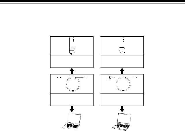
1 OVERVIEW
(2) Peripheral device configuration for the Q173DCPU/Q172DCPU
The following (a)(b) can be used.
(a) USB configuration |
(b) RS-232 configuration |
PLC CPU module (QnUD(H)CPU)
PLC CPU module (QnUD(H)CPU)
USB cable
RS-232 communication cable (QC30R2)
|
|
|
Personal computer |
|
Personal computer |
|
|
|
1 - 9
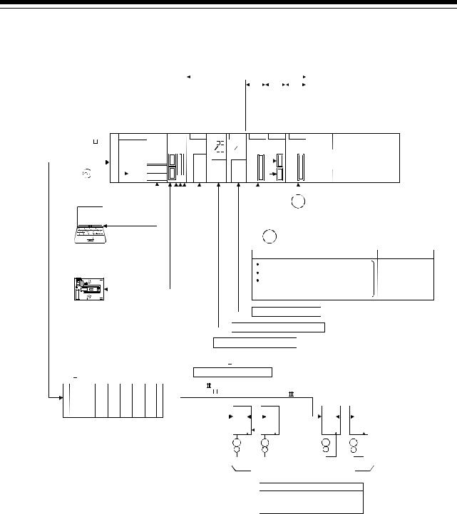
1 OVERVIEW
1.3.2 Q173DCPU System overall configuration
Motion CPU control module
|
PLC CPU/ |
|
|
|
Main base unit |
Motion CPU |
|
|
|
|
||||
|
|
|
|
|
(Q3 DB) |
Q61P QnUD(H) Q173D QI60 QX |
|||
|
CPU |
CPU |
||
QY
100/200VAC
USB/RS-232
si eSint rnger ovalaf xe ts ec erm ando l eul
Q6 AD Q172D
LX Q6 DA
DA
elu |
uel |
suo mdo esl dom nore uproe ec ltc rhda auara cof ef n r nnr yce a e nt Met Sen gn i i |
|
Q172D |
Q173D |
EX |
PX |
I/O module/
Intelligent function module
PManual pulse generator  3/module (MR-HDP01) (Up to 1 module)
Serial absolute synchronous encoder cable (Q170ENCCBL M)
M)
ESerial absolute synchronous encoder  2/module (Q170ENC) (Up to 6 modules)
Personal Computer
IBM PC/AT
Battery holder unit Q170DBATC
|
External input signals |
FLS |
: Upper stroke limit |
RLS |
: Lower stroke limit |
STOP |
: Stop signal |
 DOG/CHANGE : Proximity dog/
Speed-position switching
 Analogue input/output
 Input/output (Up to 256 points)
Interrupt signals (16 points)
Number of Inputs
8 axes/module (Up to 4 modules)
Extension cable (QC B)
B)
Extension base unit
(Q6 |
B) |
supply |
module |
Power |
UP to 7 extensions
Forced stop input cable |
|
|
|
|
||||
(Q170DEMICBL |
M) |
|
|
|
|
|||
EMI forced stop input (24VDC) |
|
|
||||||
SSCNET |
|
cable |
|
|
|
|
|
|
(MR-J3BUS M(-A/-B)) |
SSCNET |
(CN1) |
|
|||||
|
|
|
|
|
|
|||
SSCNET |
|
(CN2) |
d1 |
|
d16 |
d1 |
d16 |
|
|
|
|||||||
|
|
|
|
|
|
|
M |
|
|
|
|
M |
M |
M |
|||
|
|
|
E |
E |
E |
E |
||
MR-J3- B model Servo amplifier,
Up to 32 axes (Up to 16 axes/system)
External input signals of servo amplifier
 Proximity dog
 Upper stroke limit
 Lower stroke limit
1 - 10

1 OVERVIEW
 CAUTION
 Construct a safety circuit externally of the Motion controller or servo amplifier if the abnormal operation of the Motion controller or servo amplifier differ from the safety directive operation in the system.
 The ratings and characteristics of the parts (other than Motion controller, servo amplifier and servomotor) used in a system must be compatible with the Motion controller, servo amplifier and servomotor.
 Set the parameter values to those that are compatible with the Motion controller, servo amplifier, servomotor and regenerative resistor model and the system application. The protective functions may not function if the settings are incorrect.
1 - 11
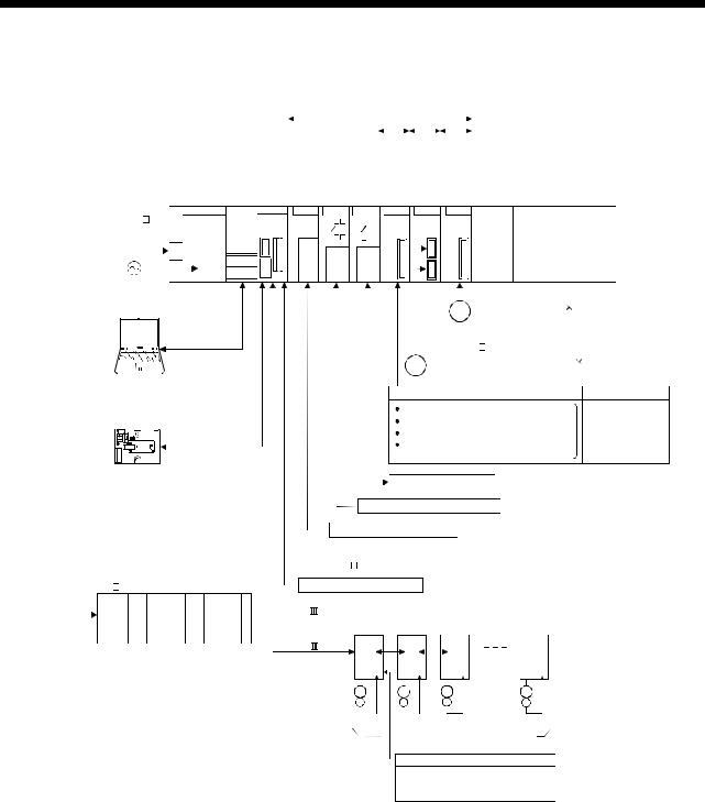
1 OVERVIEW
1.3.3 Q172DCPU System overall configuration
Motion CPU control module
|
|
|
|
|
|
|
|
|
|
|
|
|
|
|
|
Motion CPU |
|
la eudl s eudl e elud n o u o s o r m m l m e o ur t n p x e ore oe e c ec ltc osla rhda auara vaf cof ef rSengsinreti nySnecrneti Mnanegretni |
|
|||||
|
|
|
|
|
|
|
|
|
|
|
|
|
|
|
|
PLC CPU/ |
|
|
|
|
|
|
|
|
Main base unit |
|
|
|
|
|
|
|
|
|
|||||||||||||||
|
|
|
|
(Q3 DB) |
Q61P QnUD(H) Q172D QI60 QX |
Q6 |
AD Q172D |
Q172D |
Q173D |
|
||||||||||||||
|
|
|
|
|
|
|
|
|
|
|
|
|
|
|
|
CPU CPU |
|
LX |
EX |
|
PX |
|
|
|
|
|
|
|
|
|
|
|
|
|
|
|
|
|
|
|
QY |
Q6 |
DA |
|
|
|
I/O module / |
|
|
|
|
|
|
|
|
|
|
|
|
|
|
|
|
|
|
|
|
|
|
|
|
Intelligent function module |
|
|
100/200VAC |
|
|
|
|
|
|
|
|
|
|||||||||||||||
|
|
|
|
|
|
|
|
|
||||||||||||||||
|
|
|
|
|
|
|
|
|
|
|
|
|
|
|
|
|
|
|
|
|
P Manual pulse generator |
3/module |
||
|
|
|
|
|
|
|
|
|
|
|
|
|
|
|
|
|
|
|
|
|
|
(MR-HDP01)(Up to 1 module) |
||
|
|
|
|
|
|
|
|
|
|
|
|
|
|
|
USB/RS-232 |
|
|
Serial absolute synchronous encoder cable |
||||||
|
|
|
|
|
|
|
|
|
|
|
|
|
|
|
|
|
(Q170ENCCBL M) |
|
||||||
|
|
|
|
|
|
|
|
|
|
|
|
|
|
|
|
|
|
|
|
|||||
|
|
|
|
|
|
|
|
|
|
|
|
|
|
|
|
|
|
|
|
|||||
|
|
|
|
|
|
|
|
|
|
|
|
|
|
|
|
|
|
|
E |
Serial absolute synchronous encoder |
2/module |
|||
|
|
|
|
|
|
|
|
|
|
|
|
|
|
|
|
|
|
|
||||||
|
|
|
|
|
|
|
|
|
|
|
|
|
|
|
|
|
|
|
(Q170ENC)(Up to 6 modules) |
|
||||
|
|
|
|
|
|
|
|
|
|
|
|
|
|
|
|
|
|
|
|
|||||
|
|
|
|
|
|
|
|
|
|
|
|
|
|
|
|
|
|
|
|
|
||||
|
|
|
|
|
|
|
|
|
|
|
|
|
|
|
|
|
|
|
|
|
||||
|
Personal Computer |
|
|
|
|
|
External input signals |
Number of Inputs |
||||||||||||||||
IBM PC/AT |
|
|
|
|
|
|||||||||||||||||||
|
|
|
|
|
|
|
|
|
|
|
|
|
|
|
|
|
|
FLS |
|
: Upper stroke limit |
|
|||
|
|
|
|
|
|
|
|
|
|
|
|
|
|
|
|
|
|
RLS |
|
: Lower stroke limit |
8 axes/module |
|||
|
|
|
|
|
|
|
|
|
|
|
|
|
|
|
|
|
|
STOP |
|
: Stop signal |
||||
|
|
|
|
|
|
|
|
|
|
|
|
|
|
|
|
|
|
|
(Up to 4 modules) |
|||||
|
|
|
|
|
|
|
|
|
|
|
|
|
|
|
|
|
|
DOG/CHANGE : Proximity dog/ |
||||||
Battery holder unit |
|
|
|
|
|
|
Speed-position switching |
|
||||||||||||||||
|
|
Analogue input/output |
|
|||||||||||||||||||||
Q170DBATC |
|
|
|
|||||||||||||||||||||
 Input/output (Up to 256 points)
Interrupt signals (16 points)
Extension cable (QC B)
B)
Extension base unit
(Q6 |
B) |
supply |
module |
Power |
UP to 7 extensions
Forced stop input cable |
|
|
|
|
||
(Q170DEMICBL |
M) |
|
|
|
|
|
EMI forced stop input (24VDC) |
|
|
||||
SSCNET |
cable |
|
|
|
|
|
(MR-J3BUS M(-A/-B)) |
|
|
|
|
||
SSCNET |
(CN1) |
d1 |
d2 |
d3 |
d8 |
|
|
|
|
|
|
|
|
|
|
M |
M |
|
M |
M |
|
|
E |
E |
E |
E |
|
MR-J3- B model Servo amplifier,
Up to 8 axes
External input signals of servo amplifier
 Proximity dog
 Upper stroke limit
 Lower stroke limit
1 - 12

1 OVERVIEW
 CAUTION
 Construct a safety circuit externally of the Motion controller or servo amplifier if the abnormal operation of the Motion controller or servo amplifier differ from the safety directive operation in the system.
 The ratings and characteristics of the parts (other than Motion controller, servo amplifier and servomotor) used in a system must be compatible with the Motion controller, servo amplifier and servomotor.
 Set the parameter values to those that are compatible with the Motion controller, servo amplifier, servomotor and regenerative resistor model and the system application. The protective functions may not function if the settings are incorrect.
1 - 13
 Loading...