

Page 1

Service Manual
of
PM-8000
Portable Patient Monitor
Page 2

Page 3

Copyright
SHENZHEN MINDRAY® BIO-MEDICAL ELECTRONICS CO., LTD. 2002
Version: 2.0
Issued date: 2005/07/24
P/N: 8000-20-10282
Statement
SHENZHEN MINDRAY
®
BIO-MEDICAL ELECTRONICS CO., LTD. (hereinafter called Mindray)
owns all rights to this unpublished work and intends to maintain this work as confidential. Mindray
may also seek to maintain this work as an unpublished copyright. This publication is to be used solely
for the purposes of reference, operation, maintenance, or repair of Mindray equipment. No part of this
can be disseminated for other purposes.
In the event of inadvertent or deliberate publication, Mindray intends to enforce its rights to this work
under copyright laws as a published work. Those having access to this work may not copy, use, or
disclose the information in this work unless expressly authorized by Mindray to do so.
All information contained in this publication is believed to be correct. Mindray shall not be liable for
errors contained herein nor for incidental or consequential damages in connection with the furnishing,
performance, or use of this material. This publication may refer to information and protected by
copyrights or patents and does not convey any license under the patent rights of Mindray, nor the rights
of others. Mindray does not assume any liability arising out of any infringements of patents or other
rights of third parties.
Content of this manual is subject to changes without prior notice.
PROPERTY OF
SHENZHEN MINDRAY
ALL RIGHTS RESERVED
Responsibility on the manufacturer party
Service Manual of PM-8000 Portable Patient Monitor (V2.0) I
®
BIO-MEDICAL ELECTRONICS CO., LTD.
Page 4

Mindray is responsible for safety, reliability and performance of this equipment only in the condition
that:
• all installation, expansion, change, modification and repair of this equipment are conducted by
Mindray qualified personnel; and,
• applied electrical appliance is in compliance with relevant National Standards; and,
• the monitor is operated under strict observance of this manual.
′ NOTE ′
This equipment is not intended for family usage.
Warning
This monitor is not a device for treatment purpose.
It is important for the hospital or organization that employs this equipment to carry out a reasonable
maintenance schedule. Neglect of this may result in machine breakdown or injury of human health.
Upon request, Mindray may provide, with compensation, necessary circuit diagrams, calibration
illustration list and other information to help qualified technician to maintain and repair some parts,
which Mindray may define as user serviceable.
II Service Manual of PM-8000 Portable Patient Monitor (V2.0)
Page 5

Warranty
Workmanship & Materials
Mindray guarantees new equipment other than accessories to be free from defects in workmanship and
materials for a period of one year (six months for multi-site probes and SpO2 sensor) from date of
shipment under normal use and service. Mindray's obligation under this warranty is limited to repairing,
at Mindray’s option, any part which upon Mindray's examination proves defective.
THIS WARRANTY IS EXCLUSIVE AND IS IN LIEU OF ALL OTHER WARRANTIES,
EXPRESSED OR IMPLIED, INCLUDING WARRANTIES OF MERCHANT ABILITY OR
FITNESS FOR ANY PARTICULAR PURPOSE.
Exemptions
Mindray's obligation or liability under this warranty does not include any transportation or other
charges or liability for direct, indirect or consequential damages or delay resulting from the improper
use or application of the product or the substitution upon it of parts or accessories not approved by
Mindray or repaired by anyone other than a Mindray authorized representative.
This warranty shall not extend to any instrument which has been subjected to misuse, negligence or
accident; any instrument from which Mindray's original serial number tag or product identification
markings have been altered or removed, or any product of any other manufacturer.
Safety, Reliability and Performance
Mindray is not responsible for the effects on safety, reliability and performance of the PM-8000
Portable Patient Monitor if:
■ assembly operations, extensions, re-adjusts, modifications or repairs are carried out by persons
other than those authorized by Mindray.
■ the PM-8000 Portable Patient Monitor is not used in accordance with the instructions for use, or
the electrical installation of the relevant room does not comply with NFPA 70: National Electric
Code or NFPA 99: Standard for Health Care Facilities (Outside the United States, the relevant
room must comply with all electrical installation regulations mandated by the local and regional
bodies of government).
Service Manual of PM-8000 Portable Patient Monitor (V2.0) III
Page 6

Return Policy
Return Procedure
In the event that it becomes necessary to return a unit to Mindray, the following procedure should be
followed:
1. Obtain return authorization. Contact the Mindray Service Department and obtain a Customer
Service Authorization (Mindray) number. The Mindray number must appear on the outside of the
shipping container. Return shipments will not be accepted if the Mindray number is not clearly
visible. Please provide the model number, serial number, and a brief description of the reason for
return.
2. Freight policy. The customer is responsible for freight charges when equipment is shipped to
Mindray for service (this includes customs charges).
Company Contact
Address: Mindray building keji 12th road south hi-tech industrial
park nanshan Shenzhen, P.R.China
Phone: +86 755 26582658/26582888
Fax: +86 755 26582680
Free hot line: +86 800 830 3312
EC Representative
Name: Shanghai International Holding Corp. GmbH(Europe)
Address: Eiffestrasse 80 D-20537 Hamburg Germany
Phone: +49 40 2513174
Fax: +49 40 255726
IV Service Manual of PM-8000 Portable Patient Monitor (V2.0)
Page 7

Preface
This manual gives detailed description to PM-8000 Portable Patient Monitor concerning its
performance, operation, and other safety information. Reading through this manual is the first step for
the user to get familiar with the equipment and make the best out of it.
Following symbols indicates some important facts that you have to pay special attention to:
Warning Points to be noted to avoid injury to the patient and the operator.
Caution Points to be noted to avoid damage to the equipment.
′ NOTE ′ Points to be noted.
This manual is intended for persons who are trained in the use of this field and have adequate
experience in operation of monitoring equipment.
Service Manual of PM-8000 Portable Patient Monitor (V2.0) V
Page 8

Page 9

Content
Chapter 1 Introduction ........................................................................................................................1-1
I. General.................................................................................................................................... 1-1
II. Appearance............................................................................................................................ 1-2
2.1 Screen display ................................................................................................................. 1-2
2.2 Button Functions............................................................................................................. 1-6
2.3 Interfaces................................................................................................................... 1-8
2.4 Built-in rechargeable battery...................................................................................... 1-10
III. Hardware principle................................................................................................................ 1-11
3.1 Power board ............................................................................................................ 1-12
3.2 PM-8000 main control board .................................................................................. 1-13
3.3 Structure diagram .................................................................................................... 1-14
3.4 Description .............................................................................................................. 1-14
3.5 Button schematic diagram and principle................................................................. 1-16
3.6 Maintenance part of TR60-A recorder.......................................................................... 1-17
Chapter 2 Monitor Functions and Principles ......................................................................................2-1
I. Introduction ............................................................................................................................... 2-1
II. ECG/RESP parameters............................................................................................................. 2-2
2.1 ECG................................................................................................................................. 2-2
2.2 RESP ............................................................................................................................... 2-2
2.3 NIBP ............................................................................................................................... 2-3
2.4 SpO2 ............................................................................................................................... 2-3
2.5 TEMP.............................................................................................................................. 2-4
2.6 IBP .................................................................................................................................. 2-4
Chapter 3 Checks and Tests................................................................................................................3-1
I. System checks......................................................................................................................... 3-1
II. Testing and calibrating each parameter.................................................................................... 3-9
Chapter 4 Troubleshooting .................................................................................................................4-1
I. Disassembly graph of each part of PM-8000............................................................................. 4-1
II. Troubleshooting guidance ........................................................................................................ 4-2
Chapter 5 Installation..........................................................................................................................5-1
I. Unpack inspection................................................................................................................. 5-1
II. Preparations before power-on................................................................................................ 5-1
III. Turn on the power................................................................................................................... 5-1
IV. Other precautions.................................................................................................................... 5-1
Chapter 6 Basic Operations ................................................................................................................6-1
Service Manual of PM-8000 Portable Patient Monitor (V2.0) 1
Page 10

I. Basic operation guidance........................................................................................................... 6-1
II. Use PM-8000............................................................................................................................ 6-1
Chapter 7 Cleaning and Disinfection..................................................................................................7-1
I. Maintenance checks................................................................................................................ 7-1
II. General cleaning....................................................................................................................... 7-1
III. Sterilization ............................................................................................................................. 7-2
IV. Precautions and cleaning ........................................................................................................ 7-3
V. IBP transducer cleaning and disinfection(reusable) ........................................................... 7-4
VI. TEMP sensor cleaning and disinfection (reusable) ............................................................. 7-6
Chapter 8 Maintenance .......................................................................................................................8-1
Chapter 9 Network Link .....................................................................................................................9-1
I. Network performance ............................................................................................................. 9-1
II. Application ............................................................................................................................... 9-1
Appendix I: System Alarm Prompt................................................................................................... AI-i
Appendix II: Product Specifications................................................................................................ AII-i
1. Classification...........................................................................................................................AII-i
2. Specifications..........................................................................................................................AII-i
2 Service Manual of PM-8000 Portable Patient Monitor (V2.0)
Page 11

Chapter 1 Introduction
I. General
Environment:
Temperature
Working 0 ~ 40 °C
Transport and Storage -20 ~ 60 °C
Humidity
Working 15% ~ 95%
Transport and Storage 10% ~ 95%
Introduction
Altitude
Working -500 to 4,600m
Transport and Storage -500 to 13,100m
Power Supply
100~240 (V)AC, 50/60 Hz
Pmax=100VA
FUSE T 1.6A
PM-8000 Portable Patient Monitor (Figure 1-1) is adaptable to adult, pediatric and neonatal
usage. It can monitor vital signals such as ECG, Respiratory Rate, SpO2, NIBP, TEMP and IBP. It
integrates parameter measuring modules, display and recorder into one device, featuring in
compactness, lightweight and portability. Replaceable built-in battery facilitates the transportation of
patient. Large high-resolution display provides clear view of 5 waveforms and full monitoring
parameters.
PM-8000 Portable Patient Monitor performs monitoring of:
ECG
Heart Rate (HR)
2-channel ECG waveforms
Arrhythmia and S-T segment analysis(optional)
RESP
SpO2
NIBP
Service Manual of PM-8000 Portable Patient Monitor (V2.0) 1-1
Respiratory Rate (RR)
Respiration Waveform
Oxygen Saturation (SpO2), Pulse Rate (PR)
SpO2 Plethysmogram
Systolic Pressure (NS), Diastolic Pressure (ND), Mean Pressure (NM)
Page 12
Introduction
TEMP
IBP
PM-8000 provides extensive functions as visual & audible alarm, storage and report printout for
trend data, NIBP measurements, and alarm events, and drug dose calculation, etc.
Temperature DATA
IBP SYS, DIA, MAP
IBP waveform
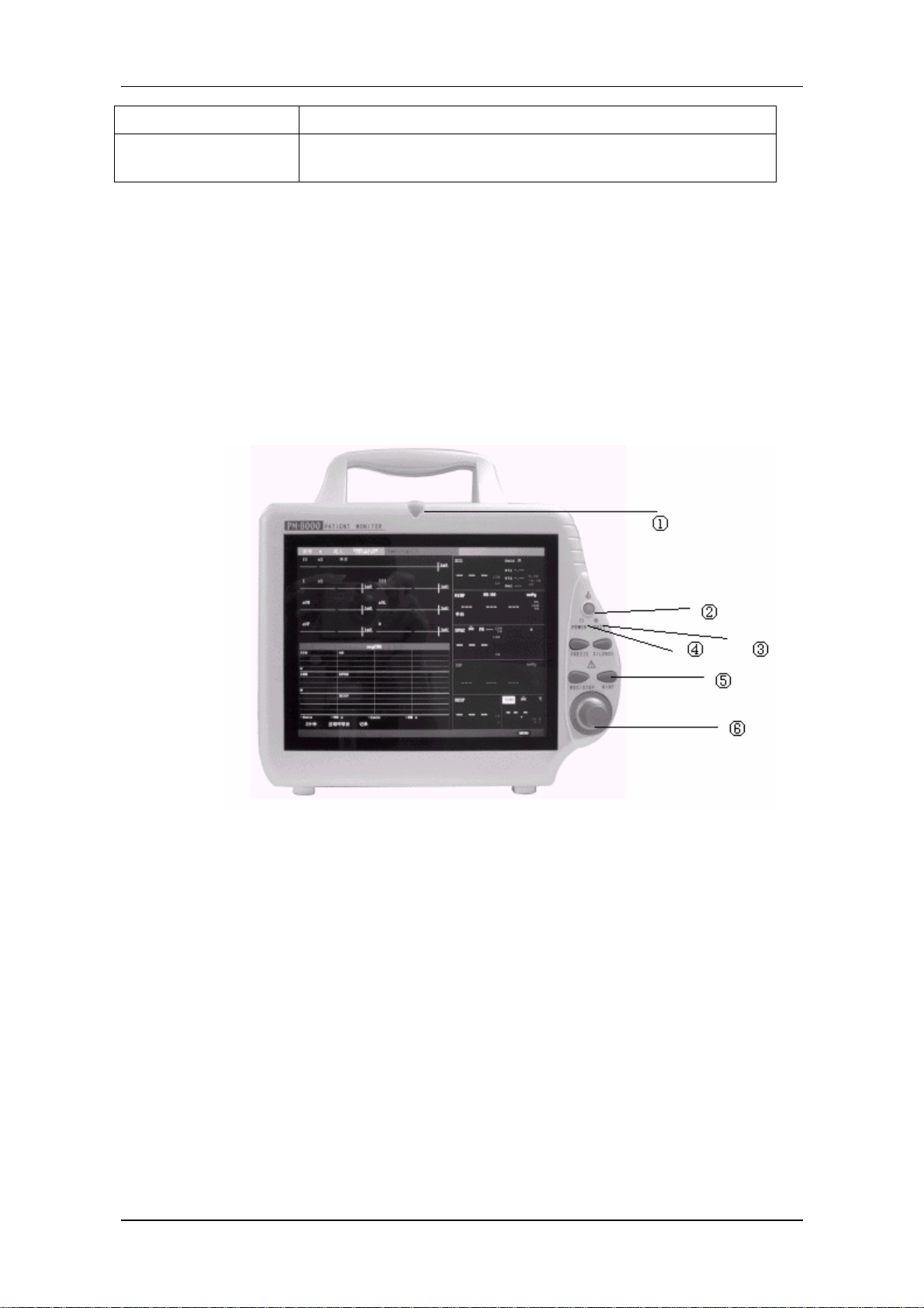
II. Appearance
The POWER switch is on the right quarter of the front panel (②). The POWER indicator(④)
and the BATT indicator (③) light when the device is powered on. The ALARM indicator flashes or
lights when alarm occurs (①). Sockets for the sensors are on the right side. The recorder socket is on
the left side. Other sockets and power plug-in are at the back.。
Figure 1-1 Front view of PM-8000 Portable Patient Monitor
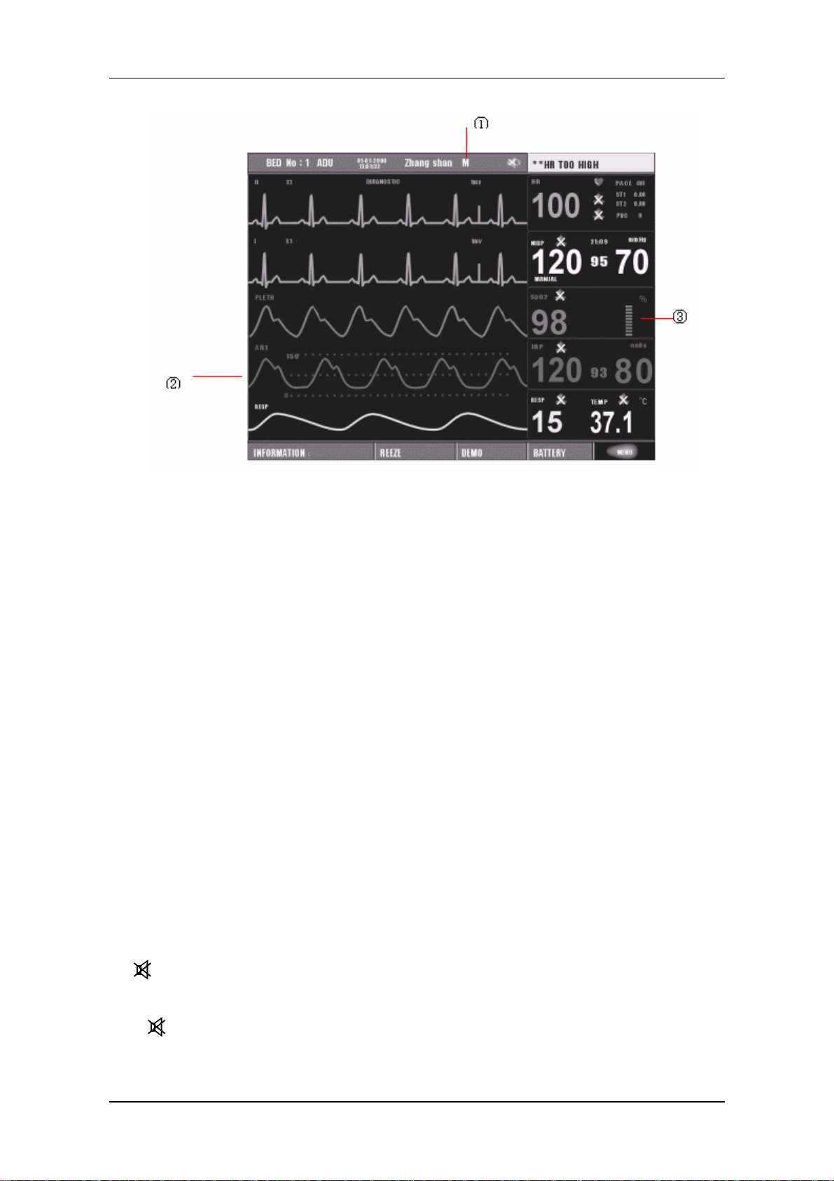
2.1 Screen display
The display of PM-8000 may be color or monochrome liquid crystal. (The monitor of PM-8000 is
available in both monochrome and color liquid crystal).Patient parameters, waveforms, alarm messages,
bed numbers, date, system status and error messages can be displayed on the screen.
The screen is divided into three areas: ← message area①; ↑ waveform area②; → parameter area
1-2 Service Manual of PM-8000 Portable Patient Monitor (V2.0)
Page 13
Introduction
Figure 1-2 PM-8000 main screen
Message Area(①)
The Message Area is at the top of the screen and used to display operating state of the monitor and
status of the patient.
The messages and their meanings are:
【BED No】 Bed number of the patient being monitored
【3/1/2001】 Current date
【10:23:45】 Current time
【M/F】 Sex of the patient being monitored
【NAME】 name of the patient being monitored. When the user is entering patient name,
the name will be displayed at this position. If no patient name is entered, this
position will be blank.
Other information in the Message Area comes up only with respective monitoring status. They are:
1. Signs indicating the operating status of the monitor and the sensors are displayed at the right side of
time numeric. When appears, this message will cover the sex and name information of the patient.
2. “
” Indicates that all sounds are disabled manually. It appears when SILENCE button is pressed
for more than 1 seconds.
3. “!
ALARM SETUP menu, this mark appears indicating that the operator has permanently closed the
Service Manual of PM-8000 Portable Patient Monitor (V2.0) 1-3
” is the sign indicating that the alarm volume is closed. When select the “OFF” option in the
Page 14

Introduction
audio alarm function. This audio alarm function can resume only after the operator discharges the setup
of Close Alarm Volume.
′ NOTE ′
When “!
the operator should be careful in using this function. One method of discharging this
status is in the ALARM SETUP menu, select the item that the alarm volume is in
Non-close. Another method is to press the SILENCE button so as to make the mark
” sign appears, the system can not give any audio alarm prompt. Therefore,
change into a
restores the normal alarm status.
4. Alarm message is displayed always at the extreme right area on the screen.
5. When waveforms on the screen are frozen, “FREEZE” window appears at the bottom of the screen.
. Then press SILENCE button again, the system will immediately
Waveform/Menu Area(②)
Five waveforms can be displayed at the same time. The waveforms from up to down are: 2 channels of
ECG waveforms, SpO2 Plethysmogram, IBP, RESP (possibly coming from ECG module). Waveforms
to be displayed are user-selectable. Refer to Tracing Waveforms Selection in Operation Manual for
details.
The names of the waveforms are displayed to their left. The names of ECG and IBP are user-selectable.
Refer to Chapter ECG/RESP Monitoring and Chapter IBP Monitoring in Operation Manual for
details. Gain and filter of this ECG channel are displayed as well. A 1mv scale is marked on the right
of ECG waveform. The IBP waveform scale is displayed in IBP wave area. The three dot lines from up
to down respectively represent the highest scale, reference scale and lowest scale of the waveform.
These values can be manually set. Refer to Chapter IBP Monitoring in Operation Manual for IBP
setup.
The same menu always appears at a fixed area on the screen. When the menu is displayed, some
waveforms become invisible. The size of the menu is also fixed, covering the lowest 3, 4 or 5
waveforms. If the system exits the menu, the screen will restore its previous look.
The waveforms are refreshed in a user-set rate. Refer to the related chapters for details of sweep speed.
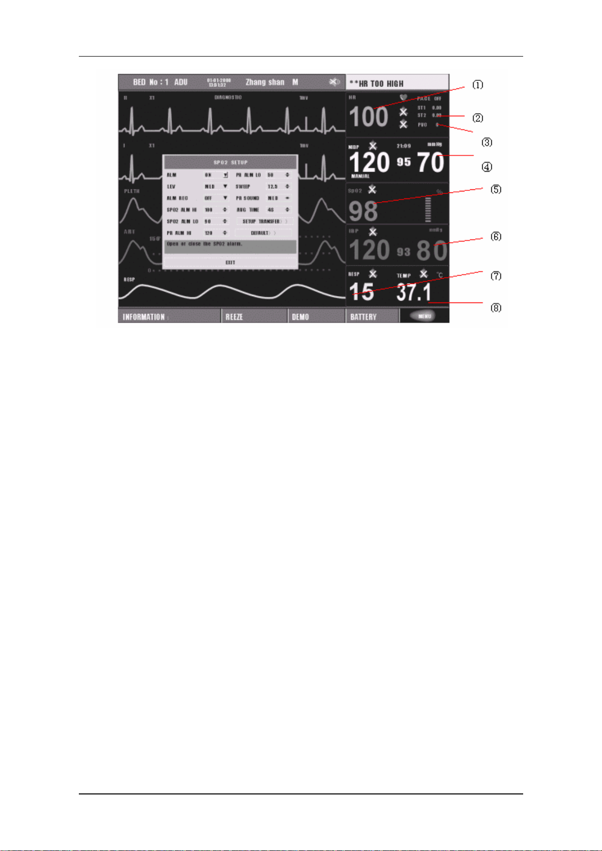
Parameter Area(③)
Parameters are displayed at a fixed position (①~⑩). They are (from top to bottom):
1-4 Service Manual of PM-8000 Portable Patient Monitor (V2.0)
Page 15
Introduction
ECG
NIBP
SpO2
IBP
Figure 1-3 Main Screen
Heart Rate (①, Unit: bpm) ⎯
⎯
ST-segment analysis of Channel 1 & 2 (②, Unit: mv)
⎯
Arrhythmia (PVCs) events (③, Unit: event/min)
⎯
(From left to right) Systolic, Mean, Diastolic (④, Unit: mmHg or kPa)
⎯
SpO2 (⑤, Unit: %)
⎯
Blood Pressure: Systolic, Mean, and Diastolic values are displayed from left to right. (⑥,
Unit: mmHg or kPa)
RESP
⎯
Respiration Rate (⑦, Unit: breath/min)
TEMP
⎯
Temperature (⑧, Unit:℃ or ℉)
Service Manual of PM-8000 Portable Patient Monitor (V2.0) 1-5
Page 16
Introduction
The above monitoring results are displayed in the Parameter Area.
The parameters refresh every second, except that the NIBP value refreshes each time when the
measurement is over.
User can select the monitor parameters, and the screen display will change accordingly.
Alarm indicator and alarm status:
In normal mode, no indicator lights.
In alarm mode, the alarm indicator lights or flashes. The color of the indicator indicates the alarm level.
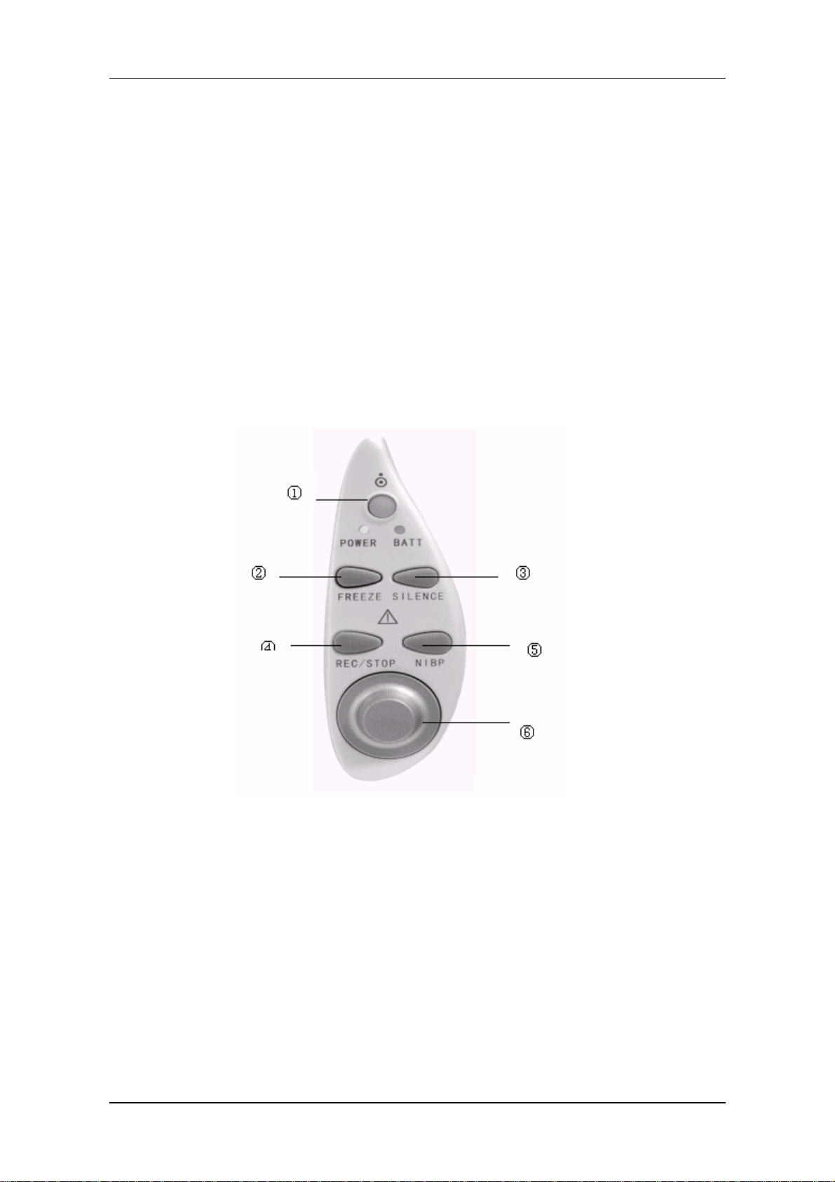
2.2 Button Functions
Figure 1-4 PM-8000 Buttons and Knob
All the operations of PM-8000 can be performed through using the buttons and the rotary knob at the
bottom of the screen. Above the buttons are their respective names. They are (from left to right):
①POWER
Press to turn on/off the monitor.
②FREEZE
When in normal mode, press to enter Freeze mode to freeze all the waveforms
on the screen. When in Freeze mode, press to restore the waveform
refreshing.
1-6 Service Manual of PM-8000 Portable Patient Monitor (V2.0)
Page 17

Introduction
③SILENCE
Press to suspend alarm for 3 minutes (it can be selected in ALARM SETUP
menu). Press this button for more than 1 seconds to disable all sound signals
(heart, beat, pulse tone, key sound), and audio alarm. A symbol “ ” displays
in the Message Area. Press this key again to restore all sound signals and
remove the “
” symbol.
NOTE:
If new alarm occurs under Alarm Suspension/Silence state,
Suspension/Silence state will change. For specific rules, see Chapter
Alarm.
NOTE:
Whether an alarm will be reset depends on the status of the alarm cause.
But by pressing SILENCE button can permanently shut off audio sound
of the ECG Lead Off and SpO2 Sensor Off alarm.
④REC/STOP
⑤START
⑥Rotary Knob
Rotary Knob
Press to start a real time recording. The recording time is set in RT
REC TIME of RECORD submenu (Refer to related sections for
details). Press during recording to stop the recording. When in
FREEZE mode, press to select the waveforms for report printout.
Refer to Chapter Recording for details.
Press to inflate the cuff to start a blood pressure measurement. When
measuring, press to cancel the measurement and deflate the cuff.
This knob can be used to select and change the settings. Operation
can be performed by turning it clockwise, counterclockwise or
pressing it down.
The square frame that moves when the knob is being turned is called "cursor". Operation can be
executed at any place where the cursor can stay. When no menu is displayed, turning the knob
clockwise can select following hot keys:
Service Manual of PM-8000 Portable Patient Monitor (V2.0) 1-7
Page 18
Introduction
Channel 1 ECG lead
Channel 1 ECG gain
ECG filter
Channel 2 ECG lead
Channel 2 ECG gain
IBP Label
ECG menu
SpO2 menu
NIBP menu
IBP menu
RESP menu
TEMP menu
When the current cursor is placed at any of the first six items, the user can change the current settings.
When at any of the last six items, related parameter menu could be called up for setting changes.
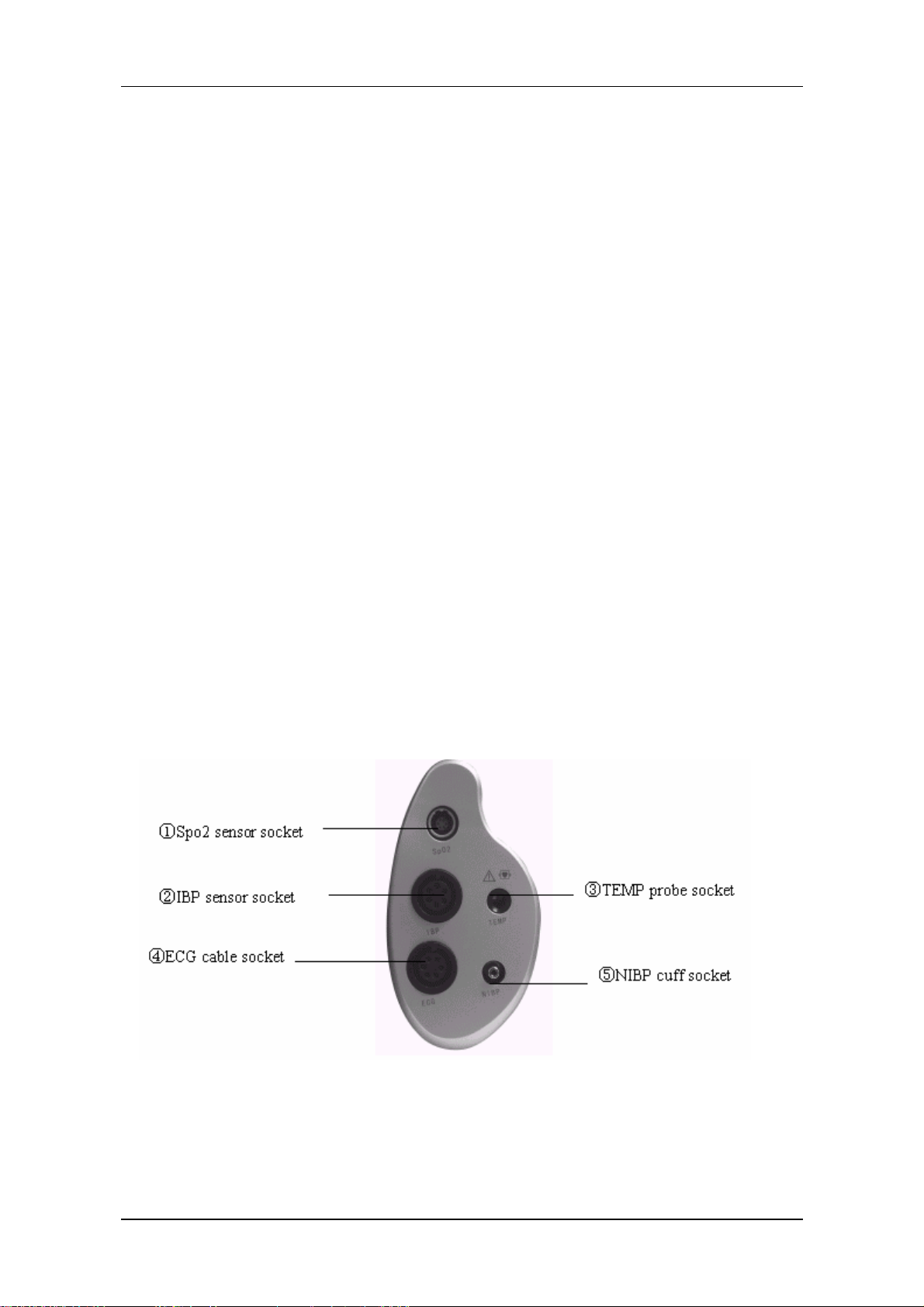
2.3 Interfaces
For the convenience of operation, different interfaces are in different parts of the monitor.
Recorder is on the left side of the monitor while sockets for patient cables and sensors are on the right
side. See the figure below:
Figure 1-5 Right side view
1-8 Service Manual of PM-8000 Portable Patient Monitor (V2.0)
Page 19
Introduction
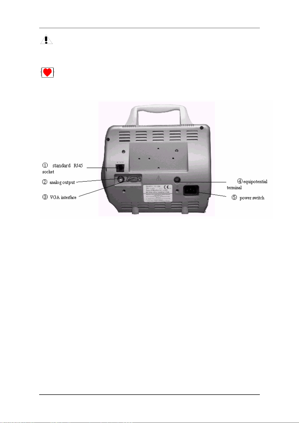
This symbol means “BE CAREFUL". Refer to the manual.
Indicates that the instrument is IEC-60601-1 Type CF equipment. The unit displaying this
symbol contains an F-Type isolated (floating) patient applied part providing a high degree of
protection against shock, and is suitable for use during defibrillation.
Figure 1-6 Rear panel
Monitor interface for external: standard VGA color monitor.
Working mode: 640 × 480, 16 color, APA mode.
Signal: analog R G B 0.7 Vpp / 750 ohm
Hor. / Vert. TTL pos. / Neg.
Interface D-sub 15 pin
Pin 1. Red Video
Pin 2. Green Video
Pin 3. Blue Video
Pin 4. Ground
Pin 5. NC
Pin 6. Red Ground
Pin 7. Green Ground
Pin 8. Blue Ground
Pin 9. NC
Pin 10. Ground
Pin 11. NC
Service Manual of PM-8000 Portable Patient Monitor (V2.0) 1-9
Page 20

Introduction
Pin 12. NC
Pin 13 Horizontal Sync.
Pin 14. Vertical Sync.
Pin 15. NC
Appliance: (Installation)
1) Install the VGA monitor at a place at least 1.5m away from the patient.(The VGA monitor
must be installed at least 1.5m away from the patient.)This monitor is used only as an
assistant monitoring device.
2) Plug the cable into proper socket before powering on the VGA monitor.
3) It is allowable to power on the VGA monitor and PM-8000 at the same time. Or power on
PM-8000 after turning on VGA monitor.
4) Adjust brightness and contrast properly.
(Socket ④)
Equipotential grounding terminal for connection with the hospital’s grounding system.
ANALOG OUTPUT (Socket ②)
Analog signal output terminal for connection with oscillometer and pen recorder.
The connection terminal is a BNC Jack.
Network Interfaces (Socket ①): Standard RJ45 Socket.
Warning
Through network interface only MINDRAY Clinical Information Center can be connected in.
Warning
Accessory equipment connected to the analog and digital interfaces must be certified according
to the respective IEC standards (e.g. IEC 60950 for data processing equipment and IEC 60601-1
for medical equipment). Furthermore all configurations shall comply with the valid version of
the system standard IEC 60601-1-1. Everybody who connects additional equipment to the signal
input part or signal output part configures a medical system, and is therefore responsible that the
system complies with the requirements of the valid version of the system standard IEC 60601-1-1.
If in doubt, consult the technical service department or your local representative.
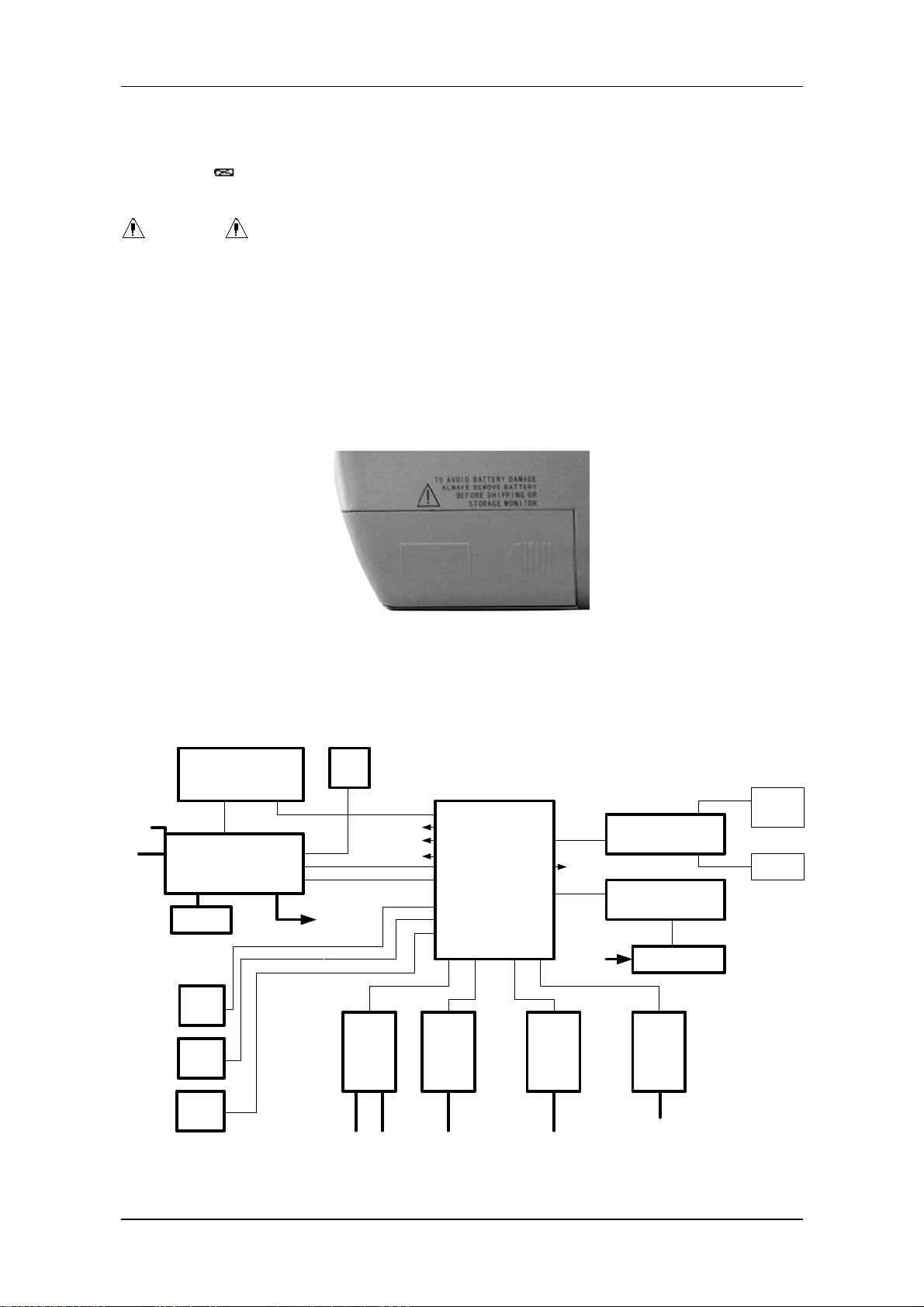
2.4 Built-in rechargeable battery
PM-8000 Portable Patient Monitor is equipped with a rechargeable battery. The battery in the Monitor
can automatically recharge when AC INPUT is connected until it is full. A symbol “
1-10 Service Manual of PM-8000 Portable Patient Monitor (V2.0)
” is displayed
Page 21
Introduction
on the bottom of the screen to indicate the status of recharging, in which the black part represents the
relative electric energy of the battery. If the battery is not installed in PM-8000, battery state will be
displayed as “
” to indicate the state. Under the cable socket is the battery slot with cover.
Warning
Don’t pull off battery when the monitor is working.
When operating on battery, the monitor will prompt alarm and shut off automatically when the energy
is low. When the electric energy is going out, the monitor will sound continuous level 1 alarm beeping
and display “BATTERY TOO LOW” in the Message Area. Connect the monitor to AC power at this
moment can recharge the battery while operating. If keep operating on the battery, the monitor will
shut off automatically (about 5 minutes since alarming) upon exhaustion of the battery.
Figure 1-7 Battery slot cover
III. Hardware principle
PM-8000 block diagram
TFT Disp lay
8.4 inchs
Main
Power
Input
X16
Power Supply P C B
J3
B a tte r y
VG A
interface
NET
In te rfa c e
Analog
output
800 X 600
X14
J6
X15
J5
J4
J2
TO X4
FAN
P14
P7(BDM)
P8
P5
P10
P13
NIBP
Module
Cuff
NIBP
P1
P4(TFT_DIGTAL)
P2(CRT)
P3(FOR 9000 VGA)
P12
P11
H o s t P .C .B .
P17(FOR 509C)
P15
P16
P6
P9
X5
ECG /
RESP/
TEM P
P.B.C.
X9 X10 X11 X12
TEM P
ECG
ECG
TEMP
Cable
Sensor
X6 X7
SPO 2
P.C.B.
SPO2
SpO2
Sensor
From J2
Key & Alarm P .C .B .
J7
X1
R ecorder M odule
X2
X3
R e c o rd e r P .S .
X4
X8
IB P
P.C.B.
IB P
IBP
Cable
Alarm
J9
J8
L E D
Speaker
Service Manual of PM-8000 Portable Patient Monitor (V2.0) 1-11
Page 22
Introduction
Figure 1-8 PM-8000 connection diagram
Following are brief description of basic function and operating principle of each part.
3.1 Power board
PM-8000 power board specifications:
AC input voltage:100~240VAC
AC input current: <1.6A
AC voltage frequency: 50/60HZ
Two-way output voltage: 5V/12V, normal working current is 1.5A for 5V, 2A for 12V.
Two-way output voltage has functions of short-circuit, over-current and over-voltage protection.
The power board has reset function.
The power board can manage the charging process of lead-acid battery (12V/2.3AH). The
charging time is about 6 hours.
Schematic diagram of power board:
AC
input
AC/DC
Battery
and
Charging
Managerent
circuit
Figure 1-9 circuit diagram of PM-8000 power board
5VDC-DC
BUCK
converter
REC POWER
SOURCE
12V output
Voltage
test
Power on/off
control circuit
Testing key points:
Connect AC power (at this time, the Charge indicator of the battery should light on).
Test before power on the monitor.
Use multimeter to measure the DC voltage of the capacitor C12, which should be within the range
of 107 ~ 354V.
Use oscillograph to measure between the PIN1 of Q1 and the negative electrode of C12, a driving
1-12 Service Manual of PM-8000 Portable Patient Monitor (V2.0)
Page 23

waveform with the frequency being about 110KHz should exist.
Use multimeter to measure the DC voltage of the capacitor C19, which should be 17.5V.
Use multimeter to measure the DC voltage of the capacitor C24, which should be 13.8V (voltage
after removing battery).
Use multimeter to measure the capacitor C47, which should be 5V.
Tests after powering on the monitor:
Use multimeter to measure the regulator ZD3 whose DC voltage should be 5V.
Use multimeter to measure the regulator ZD4 whose DC voltage should be 12V.
Use multimeter to measure the capacitor C54 whose DC voltage should be 17.2V.
3.2 PM-8000 main control board
Power supply
Introduction
Input voltage: +12V±5%;
+5V±5%;
The main control board uses the COLDFIRE series embedded microprocessor 5206e
manufactured by MOTOROLA Company. It also adopts 3.3V low-voltage power supply to reduce the
power consumption. Other main components on the main control board include: Flash, SRAM, FPGA,
network controller, etc, all of which require 3.3V power. The capacity of the Flash has been increased
to 2MB, which employs two parallel-connected 512Kx16 chips and therefore uses 32-bit character
width to support CPU to operate at the highest possible speed instead of accessing to DRAM for
operation. The main control board has also a 4MB memory, which is made up of two
parallel-connected 1M ×16-bit chips. Because no executing program is required to be loaded, only
one RTC is used. This chip uses one 225maH dry cell as the spare power supply. In addition, one 2KB
2
E
PROM is used to store parameters. The main control board supports a resolution of 800x600 and
provides three interfaces: a LVDS interface, a 6BIT DIGITAL interface, and a VGA interface. The
monitor displays both characters and waveforms in an overlapping way on the whole screen in the
same color. The characters and waveforms can be browsed in a scrolling way. The support system
needs 10 serial ports, and the baud rate (4800/9600/19.2k/38.4k/76.8k) can be online selected by
software and interface buffer drives. The main control board adopts the network controller AX88796
(3.3V, 10MHz), which has inside 16K high-speed buffer SRAM. The MAX5102 8-bit single-way D/A
converter is used to fulfil analog output. 5V and 12V stabilized voltage supplies are introduced from
the power board, and therefore 3.3V and 2.5V working supplies are respectively generated. Among
them, 2.5V is to be used for the internal verification of FPGA.
Service Manual of PM-8000 Portable Patient Monitor (V2.0) 1-13
Page 24
Introduction
3.3 Structure diagram
FPGA
RTC/E2PRO
M/Watch
Display
driving
circuit
Interrupt
manageme
nt circuit
DRAM
CPU
Multi-way
serial
Figure 1-10 Structure diagram
3.4 Description
Flash/
SRAM
Network
controller
Audio
alarm/spare
battery
3.3V low-voltage power supply component is adopted. The external power is 5V, which is converted
by the DC/DC converter into 3.3V and 2.5V, the latter voltage being especially used for FPGA. The
main control board are connected with the external devices via following interfaces and input: the
power supply connected with the interface board, the 9-way serial port, TFT interface, analog VGA
interface, network interface, analog output and a spare serial port, etc. The BDM interface is reserved
on the board for the aim of software testing and download.
■ CPU
It use Coldfire5206e. Clock rate is 54MHz, working voltage is 3.3V.
■ FLASH
It use tow parallel-connected 512Kx16 FLASH memories. The output terminal PP1 of CPU is used to
realize write-protection of FLASH. It is effective in low-level state.。
■ DRAM
PM-8000 main control board uses two parallel-connected 1Mx16 DRAM, which construct 4M address
space.
■ Display
The resolution is 800x600. Frequency is 38MHz. It works in an appropriate SVGA mode. VRAM
adopts 16-bit structure and is divided into character screen and waveform screen. On the left side of the
1-14 Service Manual of PM-8000 Portable Patient Monitor (V2.0)
Page 25

Introduction
character screen is the corresponding waveform screen. The right side to the character screen is used to
display data and flashing alarms. The user can select color and dot energy. Besides the user can scroll
the waveform for clear and complete observation.
■ LVDS interface
Through the way of time-sharing sampling, the LVDS interface converts multi-way CMOS/TTL
signals into one-way low-voltage double-frequency difference signals, which are further to be output to
the outside). LVDS interface is generally realized by special integrated circuit. The special LVDS chip
used for display is DS90CF363A. This chip converts 18-way display pixel signals and 3-way display
control signals with a total of 21-way messages into 3-way LVDS signals. Four ways of difference
signals including these 3 ways of signals and a way of phase-locked frequency are transmitted to the
display screen. On the one side of the screen, these signals are restored for driving the screen. The
working frequency of DS90CF363A is 20~65MHz.
■ Reset and parameter storage
The main control board uses an integrated chip CS124C161, which has the functions of both power-on
reset and parameter storage. This chip has a E
2
PROM with the capacity of 2K. It can be used to
on-line modify and store various nonvolatile parameters of the host. The power-on reset and
WATCHDOG functions are used to realize reset function of the main control board. When J1 is open
circuit, the software can also disable WATCHDOG by using the output wire PP0 of CPU in order to
realize the selftest of WATCHDOG. The bus interface of this chip is I
2
C.
■ Data storage
The Main control board uses one non-power-down SRAM having its internal battery to store
monitoring data. Its capacity is 2M.
■ Network controller
The network controller adopts special chip AX88796. Its working clock is 25MHz. It also has internal
16K high-speed buffer SRAM. The data bus of this chip is 16-bit width.
Service Manual of PM-8000 Portable Patient Monitor (V2.0) 1-15
Page 26

Introduction
3.5 Button schematic diagram and principle
CPU
(A T89C 2051)
BUTTON
Watch dog
RAM
128x8
RC
FILTER
serial com m unica te
Alarm indicato r
POWER
CONVERSION
Main control
board
control c ircu it
speaker
ENCO DER
button and encoder
scan circ u it
audible effect
generating/
contol circuit
button signal
input
FLASH
volume
control
2KX8
BANDPASS
Figure 1-11 Button schematic diagram
3.5.1 Principle introduction:
The circuit has three main parts;
■ Alarm audio signal circuit: audible effect generating circuit is made up of nine components, which
are U3, D1, D2, D3, Q1, C2, R15 and R9. The length of the generated aftersound is controlled by the
discharge loop constructed by C2 and R15. P3.5 is used to generate alarm square waveforms (about
700Hz). When P3.3 is 1 and Q1 is on, alarm is activated, C2 is quickly charged to the full capacity and
R10 outputs to the next phase. When P3.3 is 0, alarm is terminated, C2 discharges by using R15 so as
to produce aftersound effect. D3 and D9 are used to overlap heart beat sound. When P3.2 is 1, the
square waveform of P3.5 generates “heart beat sound” and “rotary encoder sound” through controlling
the time length of the conduction of P3.2. Together with R17, R18 or R19, R10 may respectively
construct potential-dividing network of different proportion, and consequently control the state of P3.4
and P3.7, decide make-and-break of Q2 and Q3 so as to realize the function of adjusting 3-level sound
volume.
■ RC bandpass filter: The alarm signal is square waveform with the frequency of about 700Hz. To
remove the DC component (low-frequency component) in the square waveform, a one-phase bandpass
filter is added before LM386. This filter is made up of R22, C13, C11 and the input resistance Rin of
LM386.
■ Audio amplifying circuit constructed by LM386: Generation of the visual alarm signal: The
flashing of the indicator in red or green is realized by controling the state of singlechip P1.6 and P1.7.
Scanning of buttons and encoder: Determine whether a button or the encoder is pressred through the
way of scanning the state of singlechips P1.0~P1.2. Determine whether encoder is turned and its
turning direction by scanning the state of P1.4 and P1.5.
3.5.2 Important measurement points
1-16 Service Manual of PM-8000 Portable Patient Monitor (V2.0)
Page 27

1. Test if the 5V power supply works normally (after fuse FU1);
2. Test if the crystal oscillator starts oscillating when the voltage is about between 1.5~3.5V.
3.6 Maintenance part of TR60-A recorder
3.6.1 Diagram
Introduction
Power
8.3v->5v
5v
power 8.3v->3.3v
Motor
driver
Thermal Head
cpld 9536
cpu
ad
Opto
Senser
signal
Figure 1-12 Schematic diagram of TR60-A drive board
The main function parts of the recorder are:
3.6.2 Thermal head
The thermal head is the pivot component of recorder. It is PTMBL1300A thermal head manufactured
by ALPS company.
3.6.3 CPU system
The CPU system is the core of the drive board. Its task is to receive the data from the host and generate
lattice messages after calculation using specified algorithm. These messages are then sent to the
thermal head to be printed out. The CPU system can at the same time collect messages about both
thermal head and drive board, have these messages displayed and sent to the host.
3.6.4 Power conversion
The thermal head requires two power supplies: 8.3V and 5V. CPU needs 3.3V power. 5V and 3.3V are
generated on the drive board. Components using these two power supplies are SPX5205M5 and
AS1117.
3.6.5 Motor drive
A small motor is used to control the paper movement at the thermal head. The processor on the drive
board uses two motor drives IC LB1843V to control and drive the motor. These two ICs are able to
drive the motor using constant-current. The logic drive level of the thermal head used on the
CPLD9536 drive board is 5V CMOS. The processor works under 3.3V. The system uses a CPLD
X9536XL, by which the output logic of the OC gate is generated, therefore converting 3.3V level into
5V.
3.6.6
Test points are listed out in the table below:
Service Manual of PM-8000 Portable Patient Monitor (V2.0) 1-17
Page 28

Introduction
No. Name Position Function
1 VH P1.1 or P1.2 Power input: 7.8~8.4V
2 GND P1.4 or TP16 Power and signal grounding termals
3 VPP U3.8 Thermal head heating and motor power: 8~8.4V
4 VDD U9.2 Logic component power of the drive board:
3.0~3.6V
5 VCC U4.5 Logic power of the thermal head: 4.75~5.25V
6 RESET TP30 CPU reset signal, high level after power-on:
(>2.4V)。
1-18 Service Manual of PM-8000 Portable Patient Monitor (V2.0)
Page 29

Monitoring Functions and Principles
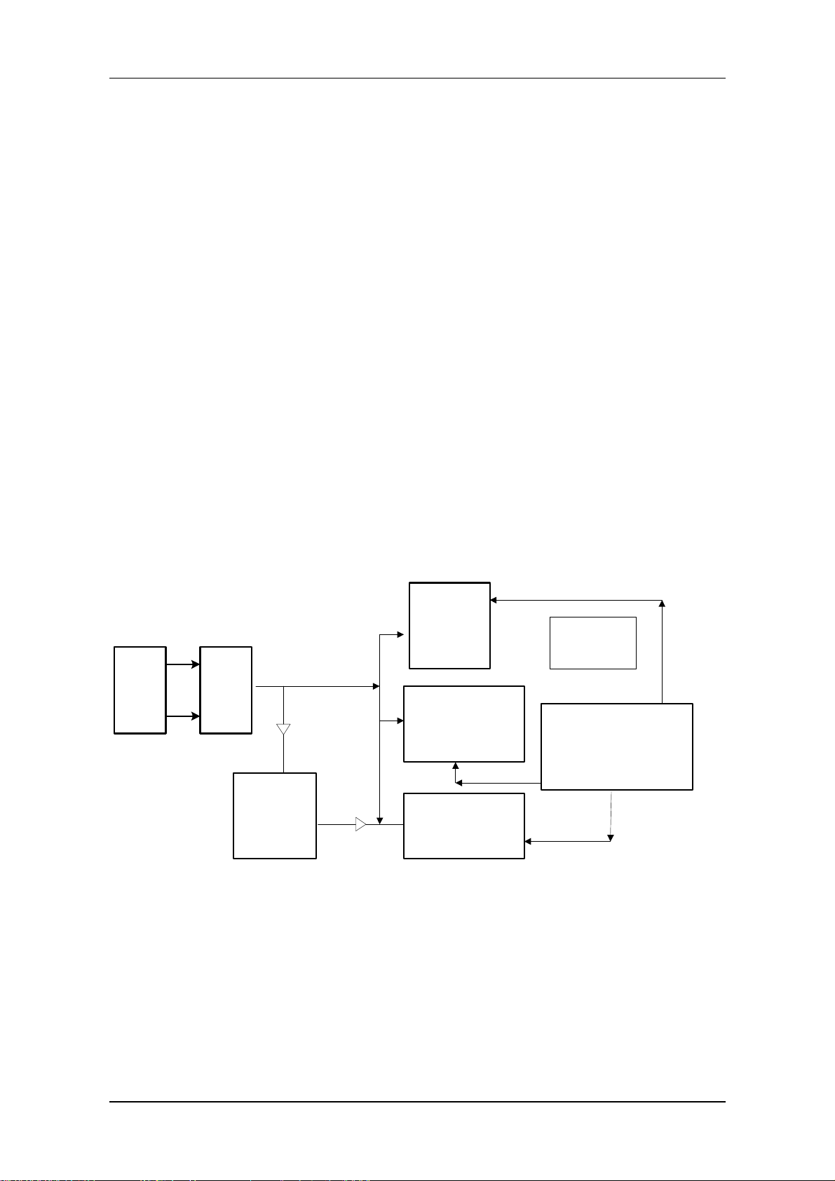
Chapter 2 Monitor Functions and Principles
I. Introduction
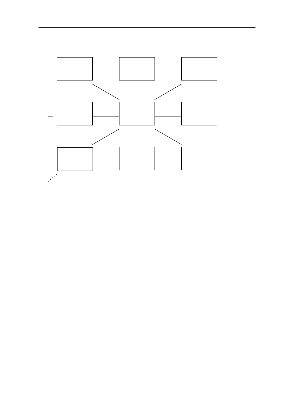
PM-8000 portable patient monitor uses parameter module as the basic unit to acquire signals. The
results are transmitted to the main control board via keyset to finally process and display the data and
waveforms. The commands of the main control board and status messages of modules are transmitted
also through the keyset. The keyset is additionally used to realize power switching and conversion. The
structure of the whole system is shown in the figure below:
---------------------------------------- Medical Staff ----------------------------------------
------------------------------------------------ Patient ---------------------------------------------
keyboard Display Recorder
Power
ECG/RESP
/TEMP
NIBP
Main
control
board
SpO2
Network
interface
IBP
Figure 2-1 System structure diagram
As shown in the above figure, the four modules of parameters execute real-time monitoring of NIBP,
SpO2, ECG/RESP/TEMP, IBP respectively through using cuff and measuring cables. The results are
transmitted to the main control board for display. When required, the results can also be printed out via
recorder. Coming up is the detailed information of functions.
Service Manual of PM-8000 Portable Patient Monitor (V2.0) 2-1
Page 30

Introduction
II. ECG/RESP parameters
2.1 ECG
Main functions concerning ECG
1)lead: 3-lead, 5-lead
2)lead method; I, II, III, avR, avL, avF, V, CAL
3)Floating input
4)right-foot drive
5)lead-off detection
6)dual-channel ECG amplification, simultaneously processing ECG signals of any two leads.
The ECG circuit is responsible for processing the ECG signals of human body. The circuit consists of
following parts;
1) input circuit: the ECG electrodes are connected into the circuit through the cable. This circuit is
mainly used to protect ECG input stage, filter the signals so as to remove the outside interference.
2) buffer amplifying circuit: used to convert the impedance of ECG signals, so as to ensure that the
ECG has a very high input impedance but only low output impedance.
3) right-foot drive circuit: the middle output point of the buffer amplifying circuit is reversely
amplified and then fed to the RL of the 5-lead ECG to maintain the human body in a equipotential state.
This method can reduce the interference and raise the common-mode rejection ratio of the circuit.
4) lead-off detection: based on the theory that the lead-off may cause the output of the buffer
amplifying circuit to change, we can use the comparator to accurately determine if the lead has fallen
off. In this way, the level can also be converted into TTl level for the singlechip to test.
5) lead connection circuit: under the control of singlechip and as per requirement, we can connect
different lead electrodes into the main amplifying circuit for amplification.
6) main amplifying circuit: a measurement amplifier constructed by three standard operation
amplifiers.
7) Last stage processing circuit: used mainly to couple ECG signals, program control the magnitude of
the gain, filter the waveform and move the level, amplify the signal and send it to the analog-to-digital
converter.
2.2 RESP
The Monitor measures temperature by measuring the changes in resistance of a thermistor located in
the temperature lead. When a person is respiring, his chest goes up and down. This movement equals to
2-2 Service Manual of PM-8000 Portable Patient Monitor (V2.0)
Page 31

Monitoring Functions and Principles
the impedance changes between electrodes RL and LL. The monitor converts the high-frequency
signals passing through RL and LL into amplitude-modulated high-frequency signals, which are then
demodulated and amplified into electronic signals varying with the respiration changes and then
transmitted to analog-digital converter. RESP module is made up of a respiration circuit board and a
coupling transformer. The circuit includes such parts as oscillation, coupling, demodulation,
preliminary amplification, and high-gain amplification, etc.
2.3 NIBP
The monitor measures non-invasive blood pressure using the oscillometric method. Following are
detailed measurement procedures. Inflate the cuff encircled around the upper arm until the pressure in
the cuff blocking the blood flow in the artery of the upper arm. Then deflate the cuff according to the
requirement of a certain algorithm. With the pressure decreasing in the cuff, the artery blood will
palpitate with the pulse, which results in pulsation in the cuff. Through the pressure sensor connected
with the inflating pipe of the cuff, a pulsation signal palpitating with the pulse will be generated. After
being filtered by a high-pass filter (about 1Hz), this signal becomes pulsating signal and is amplified.
Then the amplified signal is converted into digital signal by A/D. After using the single chip to process
this digital signal, we may obtain systolic pressure, diastolic pressure and mean pressure. Be careful to
choose appropriate cuffs for neonatal, pediatric and adult patients so as to avoid generating
measurement errors. NIBP module also has protection circuit to prevent the cuff from being inflated to
a very high pressure. The main operating modes of NIBP are;
1) adult/pediatric/neonate: select according to the patient shape, weight and age.
2) manual measurement, auto measurement, continuous measurement. Manual measurement is also
called single measurement. It means the monitor only performs one measurement for each time. Auto
measurement means to perform one measurement within selected cycle. Time interval can be set up as
1, 2, 3, 4, 5, 10, 15, 30, 60, 90, 120, 180, 240 and 480 minutes. Continuous measurement means after
being activated, the monitor will perform quick measurement continuously within 5 minutes.
Continuous measurement is effective in monitoring changes of blood pressure.
2.4 SpO2
SpO2 Plethysmogram measurement is employed to determine the oxygen saturation of hemoglobin in
the arterial blood. If, for example, 97% hemoglobin molecules in the red blood cells of the arterial
blood combine with oxygen, then the blood has a SpO2 oxygen saturation of 97%. The SpO2 numeric
on the monitor will read 97% .The SpO2 numeric shows the percentage of hemoglobin molecules
which have combined with oxygen molecules to form oxyhemoglobin. The SpO2/PLETH parameter
can also provide a pulse rate signal and a plethysmogram wave. Arterial oxygen saturation is measured
Service Manual of PM-8000 Portable Patient Monitor (V2.0) 2-3
Page 32

Introduction
by a method called pulse oximetry. It is a continuous, non-invasive method based on the different
absorption spectra of reduced hemoglobin and oxyhemoglobin. It measures how much light, sent from
light sources on one side of the sensor, is transmitted through patient tissue (such as a finger or an ear),
to a receiver on the other side.
The sensor measurement wavelengths are nominally 660nm for the Red LED and 940nm for Infrared
LED. Maximum optical power output for LED is 4 mW. The amount of light transmitted depends on
many factors, most of which are constant. However, one of these factors, the blood flow in the arteries,
varies with time, because it is pulsating. By measuring the light absorption during a pulsation, it is
possible to derive the oxygen saturation of the arterial blood. Detecting the pulsation gives a PLETH
waveform and pulse rate signal. The SpO
value and the PLETH waveform can be displayed on the
2
main screen.
2.5 TEMP
Technical specifications:
Measurement and alarm range: 0 ~ 50 °C
Resolution: 0.1°C
Accuracy: ±0.1°C
Refreshing time: about 1 second
Average time constant: < 10 seconds
2.6 IBP
IBP monitors arterial pressure, central venous pressure and pulmonary arterial pressure.
Measurement method:
Stab and implant the catheter into the blood vessel of the part to be measured. The end of the catheter
located outside human body connects directly with the pressure transducer. Injectate normal saline into
the catheter. Because the liquid can transfer pressure, the pressure inside the blood vessel can be
transferred to the outside pressure transducer. In this way we can at any time obtain the dynamic
waveform of the changing pressure inside the vessel. By using specified calculating formula, we can
calculate systolic, diastolic and mean pressures.
2-4 Service Manual of PM-8000 Portable Patient Monitor (V2.0)
Page 33

Checks and Tests
Chapter 3 Checks and Tests
I. System checks
For the conventional testing contents of PM-8000 portable patient monitor, please refer to its Operation
Manual. The information in this chapter is only a brief introduction. The following sections are used to
emphasize important tests and the information not clearly specified in the Operation Manual.
1. Device appearance and installation checks
1)The shell of the device is clean and has no scratches. The installation is stable. When shaking the
device, these are no inside leftovers.
2)Buttons are smooth and free for operation.
3)Labels are complete and sufficient and correct in delivering information.
4)Standard configuration is complete, the sockets are installed safely.
5)Perform vibration test on the overall device before performing following operating tests.
2.Safety tests
2.1.Test equipment
1. Safety analyzer 501 PRO 1
2. Leakage current/grounding resistance measurement kit: 1
3. Connection kit of the application part: 1
4. Tinsel 20cm X 10cm 1
2.2.Test procedures
2.2.1 Leakage current to earth
2.2.1.1 Connection graph for testing is as shown in figure 3-1:
Connect one end of the 3-core power wire to AC220V network power, the other end
to the leakage current testing kit (A). Insert the 3-core power wire of safety
analyzer (B) into power output socket of (A). Connect the 3-core power wire of the
device being tested ① into AC output of 501. Connect the sensor of the
application part based on the requirements of (C). Connect the red measurement
clip RED of 501 to the ground protection PE terminal. Connect the SUM terminal
of (C) to the P terminal of (A). Locate all switches to “OFF” position.
(A)-----grounding resistance/leakage current measurement kit
(B)-----501 safety analyzer
(C)-----application part processing kit
① ------device being tested
Service Manual of PM-8000 Portable Patient Monitor (V2.0) 3-1
Page 34

Checks and Tests
⑤ ------application part
RED---501 red measurement clip
SUM--- kit post
Figure 3-1 Leakage current testing connection
between grounding terminal and the earth
2.2.1.2 Adjust input voltage: When the device being tested is in shutdown state,
connect leakage current measurement kit (A) with the input network voltage
AC220V. Adjust the booster to raise the testing voltage to 110% (that is 253V) of
the nominal voltage 230V. This voltage is monitored by the voltage meter of (A).
Then turn on the device to let the device be in the operating state, micro-adjust the
booster to make the output voltage keep stablely at 253V. Press the [Ground] key
of the 501 tester and disconnect the grounding wire.
2.2.1.3 Leakage current between network source and earth in normal state: press
the [Leakage] key of the 501 tester and read the leakage current value on it.
Connect SW12, in the condition that the application part is connected to the earth,
respectively press and release [Polarity] key to toggle between the null line and the
live wire. Then disconnect SW12 and cut off the connection between the
application part and the earth. Respectively press and release the [Polarity] key.
The maximum value of these four measurements should be less than 0.5mA.
2.2.1.4 Leakage current between network source and the earth in single fault
condition:
Leakage current when connection between null line and live wire is being cut off:
press the [Leakage] key of the 501 tester. Then press the [neutral] key of the 501
tester, disconnect N line. Respectively press and release the [Polarity] key to
toggle between null line and live wire, and imitate the condition that L line is
3-2 Service Manual of PM-8000 Portable Patient Monitor (V2.0)
Page 35

Checks and Tests
disconnected. Read the leakage current value on the 501 tester. Connect SW12,
respectively press and release the [Polarity] key. Disconnect SW12, respectively
press and release the [Polarity] key. The maximum value of these four
measurements should be less than 1.0mA.
2.2.2 Shell leakage current:
2.2.2.1 Connection graph for testing is shown in figure 3-2:
Connect one end of the 3-core power wire to AC220V network power, the other end
to leakage current testing kit (A). Insert the 3-core power wire of safety analyzer
(B) into power output socket of (A). Connect the 3-core power wire of the device
being tested① into AC output of 501. Connect the sensor of the application part
based on the requirements of (C). Stick the tinsel A on any position of ① (never
let A touch live part, protection earth and the application part).Connect the red
clip RED of the 501 tester onto the tinsel A. Connect the SUM terminal of (C) to
the P terminal of (A). Locate all switches to “OFF” position.
Figure 3-2 Connection graph for leakage current
testing between the shell and the earth
(A)-----grounding resistance/leakage current measurement kit
(B)-----501 safety analyzer
(C)-----application part processing kit
① ------device being tested
⑤ ------application part
A-------tinsel
RED---red measurement clip of 501
SUM---kit post
2.2.2.2 leakage current between the shell to protection earth in the normal state:
Service Manual of PM-8000 Portable Patient Monitor (V2.0) 3-3
Page 36

Checks and Tests
(adjust the input voltage by referring to 3.1.2) press the [Leakage] of the 501
tester and read the leakage current value on the 501. Connect SW, respectively
press and release the [Polarity] key. Disconnect SW, respectively press and release
the [Polarity] key. The maximum value of these four measurements should be less
than 0.1mA.
2.2.2.3 Leakage current between the shell and protection earth in single fault
condition:
2.2.2.3.1 Leakage current when ground wire is disconnected: press the [Leakage]
key of the 501 tester. Press the [Ground] key and disconnect the ground wire.
Connect SW and respectively press and release the [Polarity] key. Disconnect SW,
respectively press and release the [Polarity] key. The maximum value of these four
measurements should be less than 0.5mA.
2.2.2.3.2 Leakage current when null line and live wire are disconnected: press the
[Leakage] key of the 501 tester. Press the [Neutral] key of the 501 tester.
Disconnect N line, respectively press and release the [Polarity] key and toggle
between null line and live wire. Imitate the condition that L line is disconnected
and read the leakage current value on the 501 tester. Connect SW, respectively
press and release the [Polarity] key. Disconnect SW and respectively press and
release the [Polarity] key. The maximum value of these four measurements should
be less than 0.5mA.
2.3 Patient leakage current of the application part::
2.2.3.1 Connection graph for testing is shown in figure 3-3:
Connect one end of the 3-core power wire to AC220V network source, the other
end to leakage current testing kit (A). Insert the 3-core power wire of the 501
analyzer into its output socket. Connect the 3-core power wire of the device being
to be tested ① into AC output of 501. Connect the sensors including RA, LA, LL,
RL, V, NIBP, SpO2, TEMP1, TEMP2 and IBP of the application part based on the
requirements of (C). Connect the output SUM of (C0 to the RA post of the 501
tester. Locate all the switches on the connecting kit of the application part to [OFF]
position.
3-4 Service Manual of PM-8000 Portable Patient Monitor (V2.0)
Page 37

Checks and Tests
Figure 3-3 Connection graph for leakage current testing
between application part (patient) and the earth
(A)-----grounding resistance/leakage current testing kit
(B)-----501 safety analyzer
(C)-----application part processing kit
① -----device being tested
⑤ -----application part
P3----sensor connected with the patient
RA----RA terminal of ECG measuring post of 501
SUM--- kit post
2.2.3.2 Patient leakage current in the normal state: (adjust the input voltage by
referring to 3.1.2) Press the [ECG leak] key of 501, then press the arrow on the
panel of 501 to select the RA-GND item. The measured leakage current should be
less than 0.01mA.
2.2.3.3 Patient leakage current in single fault condition:
2.2.3.3.1 Press the [ECG leak] key of 501, then press the arrow on the panel of 501
to select the RA-GND item. Take turns to operate the [Ground] key (for
disconnecting the ground wire), the [Neutral] key (for disconnecting the null line)
and the [Polarity] key (for toggling between null line and live wire). Test the AC
leakage current in the above these fault conditions. The maximum current value
should be less than 0.05mA.
2.2.3.3.2 Press the [DC Only] key of 501, take turns to operate the [Ground] key
(for disconnecting the ground wire), the [Neutral] key (for disconnecting the null
Service Manual of PM-8000 Portable Patient Monitor (V2.0) 3-5
Page 38

Checks and Tests
line) and the [Polarity] key (for toggling between null line and live wire). Test the
DC leakage current in the above three fault conditions, the maximum current value
should be less than 0.05mA.
2.2.3.4 Patient leakage current of the application part when network voltage is
added.
2.2.3.4.1 Press the [ECG leak] key of 501, then press the arrow on the panel of 501
to select the RA-GND item. Press the [Isolation] key and add network voltage. Test
the leakage current of the added network voltage. The maximum current value
should be less than 0.05mA.
2.2.4 Patient auxiliary current:
2.2.4.1 Connection graph for testing is shown in figure 3-4
Connect one end of the 3-core power wire to AC220V network electical source, the
other end to leakage current testing kit (A). Insert the 3-core power wire of the 501
analyzer into its output socket. Connect the 3-core power wire of the device being
to be tested ① into AC output of 501. Connect the sensors of the application part
according to the requirements of (C). Connect the output RA-P of (C) to the RA
binding post of 501. Short-circuit connect LA-P, LL-P, RL-P, V-P, NIBP-P,
SpO2-P, TEMP1-P, TEMP2-P, IBP-P respectively onto the SUM binding post. Then
through SUM, use lead to to connect them to the LL binding post.
(A)-----grounding resistance/leakage current measurement kit
(B)-----501 safety analyzer
(C)-----application part processing kit
① -----device being tested
⑤ -----application part
P3----sensors connected to the patient
RA----RA terminal of the ECG measuring post of 501
LL----LL terminal of the ECG measuring post of 501
SUM---kit post
3-6 Service Manual of PM-8000 Portable Patient Monitor (V2.0)
Page 39

Checks and Tests
Figure 3-4 Connection graph for testing patient auxillary
leakage current
2.2.4.2 Patient auxiliary current in the normal state (adjust the input voltage by
referring to 3.1.2)
AC auxiliary current of the RA lead of ECG to other application parts: position the
RA on the connection kit of the application part to “ON” and other switches to
“OFF”. Connect RA-P to the RA binding post of 501. Connect other patient parts
to LL through SUM. Press the [ECG leak] key of 501, then press the arrow on the
panel of 501 to select the RA-LL item. The tested current value should be less than
0.01mA.
2.2.4.3 Patient auxiliary current in single fault condition:
2.2.4.3.1 AC auxiliary current of RA lead of ECGT to other application parts (AC
value of RA). Position the RA on the connection kit of the application part to
“ON” and other switches to “OFF”. Connect RA-P to the RA post of 501. Connect
other parts to LL through SUM. Press the [ECG leak] key of 501, then press the
arrow on the panel of 501 to select the RA-LL item. Take turns to operate the
[Ground] key (for disconnecting the ground wire), the [Neutral] key (for
disconnecting the null line) and the [Polarity] key (for toggling between null line
and live wire). Test the current in the above three fault conditions, the maximum
current value should be less than 0.05mA.
2.2.4.3.2 DC auxiliary current of the RA lead of ECG to other application parts
(DC value of RA):
Press the [DC Only] key of 501, take turns to operate the [Ground] key (for
disconnecting the ground wire), the [Neutral] key (for disconnecting the null line)
and the [Polarity] key (for toggling between null line and live wire). Test the
current in the above three fault conditions, the maximum current value should be
less than 0.05mA.
Service Manual of PM-8000 Portable Patient Monitor (V2.0) 3-7
Page 40

Checks and Tests
2.2.5 Testing grounding resistance
2.2.5.1 Connection graph for testing ground resistance is shown in figure 3-5:
Note: In the graph, P1 and P2 are two binding post of grounding resistance testing
kit. Keep the measuring wires “Black” and “Red” as short as possible. The
sectional area of the wire should be larger than 10mm
2
. It is acceptable to use more
than 3 pieces of parallel-connected 10WAG wires. GND is the grounding terminal
of either the power wire of the device being tested or the power plug. EP is the
grounding terminal to the device (for the current patient monitor, EP is
equipotential binding post). C are all the protecting metal covers (shells) that are
connected to PE. M are all metal screws that are connected onto EP. C and M are
all on the device shell.
Figure 3-5 Connection graph for testing
grounding resistance
2.2.5.2 Testing procedures
2.2.5.2.1 Between GND of power wire and EP: Zero the booster on (A), Connect
black wire of P1 to GND of the 3-core power wire, and the red wire to the EP
binding post. Connect network voltage 220V. Slowly adjust and raise the booster
output and observe the reading on current meter for (A). Continue to raise the
booster output until the reading of the current meter indicates 25A. Wait for 5
seconds and then read the value on the voltage meter (use AC voltage range of the
multimeter), which should be less than 5V.
2.2.5.2.2 Between GND of power plug and EP: Zero the booster, Connect black
wire of P1 to GND of the 3-core power wire, and the red wire to the EP binding
post. Connect network voltage 220V. Slowly adjust and raise the booster output
and observe the reading on the current meter. Continue to raise the booster output
until the reading of the current meter indicates 25A. Wait for 5 seconds and then
read the value on the voltage meter (use AC voltage range of the multimeter),
which should be less than 2.5V.
3-8 Service Manual of PM-8000 Portable Patient Monitor (V2.0)
Page 41

Checks and Tests
2.2.5.2.3 Between GND of power plug and each C point: Zero the booster on (A),
Connect black wire of P1 to GND of the 3-core power wire, and the red wire to the
selected C shell (cover). Connect network voltage 220V. Slowly adjust and raise
the booster output and observe the reading on the current meter. Continue to raise
the booster output until the reading of the current meter indicates 25A. Wait for 5
seconds and then read the value on the voltage meter (use AC voltage range of the
multimeter), which should be less than 2.5V.
2.2.5.2.4 Between GND of power plug and each M point: Zero the booster on (A),
Connect black wire of P1 to GND of the 3-core power wire, and the red wire to the
selected M screw. Connect network voltage 220V. Slowly adjust and raise the
booster output and observe the reading on the current meter. Continue to raise the
booster output until the reading of the current meter indicates 25A. Wait for 5
seconds and then read the value on the voltage meter (use AC voltage range of the
multimeter), which should be less than 2.5V.
II. Testing and calibrating each parameter
Testing and calibrating follow parameters are to ensure the accuracy of PM-8000 portable patient
monitor. Calibrating operation should be performed at least once a year. Calibration should be carried
out each time after maintenance.
1.Testing ECG and RESP
1)Testing tool
Human physiological signals simulator
2)Testing procedures
① Use measuring cable to connect thesimulator into the ECG socket of PM-8000
② Confirm if the number of ECG waveforms displayed on the screen is consistent with that indicated
in the ECG MENU and Factory MENU.
③ In default configuration, select lead II for ECG1 and lead I for ECG2 (if there is ECG2)
④ Check if ECG waveforms and RESP waveforms are normally displayed.
⑤ Set up the parameters of the simulator as following;
HR=30(gain×4)
RR=15
⑥ Check if the displayed ECG and RESP waveforms, HR and RR values are correct.
⑦ Change the simulator configuration
HR=240
RR=120
⑧ Check if the displayed ECG and RESP waveforms, HR and RR values are consistent with the
parameters set up on the simulator.
Service Manual of PM-8000 Portable Patient Monitor (V2.0) 3-9
Page 42

Checks and Tests
⑨ Make the ECG lead fall off, in this condition, the PM-8000 should immediate give alarm.
2.Testing NIBP
1)Testing tool
NIBP simulator
2)Testing procedures
Use the NIBP simulator with calibrating function. Calibrate the blood pressure pump and determine its
accuracy according to the calibrating method given in the Operation Manual. If it passes the calibration,
continue to perform following tests.
① Select Adult mode for both simulator and PM-8000
② Select a group of blood pressure values within the measurement range on the NIBP simulator, such
as:
NS=90
NM=70
ND=60
③ Check if the actual measured values of PM-8000 are consistent to those set up on the simulator.
④ Change the setup values on the simulator, and test again.
⑤ Check if the actual measured values are consistent with setup one.
3.Testing SpO2
1)Testing tool
SpO2 simulator
2)Testing procedures
① Connect SpO2 simulator with the SpO2 probe of PM-8000
② Set up the parameters of SpO
SpO
=98
2
simulator as following:
2
PR=70
③ Check if the displayed SpO
and PR values on PM-8000 are consistent with those on the
2
simulator.
(Note: To observe the PR value, select PLETH as the HR source in the ECG menu.)
④ Change the setup values of SpO
and PR on the simulator.
2
⑤ Check the displayed values on PM-8000 are consistent with the setup values.
⑥ Make SpO
sensor fall off, in this condition, PM-8000 should immediately give alarm.
2
4.Testing TEMP
1)Testing tool
Human physiological signals simulator
2)Testing procedures
① Connect one end of the TEMP sensor to the simulator and the other end to the TEMP socket of
3-10 Service Manual of PM-8000 Portable Patient Monitor (V2.0)
Page 43

Checks and Tests
PM-8000.
② Using the simulator to set up : EMP=34℃.
③ Check if the displayed TEMP value on the screen of PM-8000 is 34℃.
④ Change the setup value of the simulator to: TEMP=40℃.
⑤ Check if the displayed TEMP value on the screen of PM-8000 is 40℃.
5 Testing IBP
1)Testing tool
Human physiological signals simulator
2)Testing procedures
Set up the BP sensitivity of the simulator to 5uv/v/mmHg, and BP to 0mmHg. Set up the name of IBP1
to ART. Access the PRESSURE ZERO option of IBP SETUP MENU of PM-8000, zero Channel 1 to
perform zero calibration for IBP. After the zero calibration is successful, exit the menu to enter the
main screen. Set up the BP of the simulator to 200mmHg. Access the CALIBRATION menu of
PM-8000 to perform calibration operation. After the calibration is successful, exit the menu.
Set up the BP of the simulator respectively to 40mmHg, 100mmHg, and 200mmHg. In the mean time,
the screen should respectively display 40±1mmHg, 100±2mmHg, and 200±4mmHg.
Set up the output of the simulator as the ART wave. As the result, the screen should display the
corresponding waveform correctly.
Plug off the IBP sensor. The screen should display “IBP: SENSOR 1 OFF!” “IBP: SENSOR 2 OFF!”.
Plug OHMEDA cable into IBP1 channel, the display of “IBP: SENSOR 1 OFF!”. Should disappear
from the screen.
Service Manual of PM-8000 Portable Patient Monitor (V2.0) 3-11
Page 44

Page 45

Chapter 4 Troubleshooting
I. Disassembly graph of each part of PM-8000
Troubleshooting
1 Front panel assembly 6 Main bracket assembly
2 Rear panel assembly 7 Cross panhead cuspless screw PT3x10
3 Battery door 8 Cross panhead screw M3x6
4 Sockets cover 9 Cross panhead screw with gasket M3x8
5 TR60-A recorder
Service Manual of PM-8000 Portable Patient Monitor (V2.0) 4-1
Page 46

Troubleshooting
1 Main bracket 10 back board assebmly
2 Main control board 11 TFT screen assebmly
3 6200 ECG/TEMP/RESP board 12 Power board
4 6200 SpO2 board 13 Speaker assembly
5 Battery hook 14 Cross panhead screw M3x6
6 ECG insulation film 15 Recorder power wire
7 Parameter sockets assembly 16 Recorder insulation film
8 6200 recorder power board 17 Power supply insulation film
9 NIBP/IBP bracket assembly
II. Troubleshooting guidance
In transportation, storage and use of PM-8000, various factors such as unstable network voltage,
changing environmental temperature, falling-down or impact, component aging may all result in
PM-8000 failures and therefore affect normal application of the device. In failure conditions,
professional personnel with the experience of repairing electronic medical devices should perform
component-level upkeep as per the failure classification listed in the table below. Component-level
upkeep means based on analyzing, replacing or trial-operating component, we can pinpoint the failure
on a certain component of the device, such as power board, main control board, TFT assembly,
measuring cable or parameter module, etc. Repair of only some components means component-level
repair. The repair operation must be conducted by a service engineer with abundant experience and
with the assistance of special equipment and in specific environment and conditions.
4-2 Service Manual of PM-8000 Portable Patient Monitor (V2.0)
Page 47

PM-8000 Component-level Service Table
2.1 Device failures
Failure Possible cause Solution
①fuse damage ①replace fuse
Troubleshooting
No display after power-on,
power indicator does not light
on, fan does not run.
No display after power-on or
black screen during operation,
however, power indicator
lights on and fan runs
normally.
Characters are displayed
normally, however waveforms
are displayed intermittently.
An operation or measurement
function is disabled.
②power damage ②replace power
③component short-circuit ③ anchor the short-circuit
component
①main control board failure
or display failure
① Data communication error
between main control board
and parameter module
① main control board or
corresponding component
damage
① refer to the information about
confirming display failure
①Based on error prompt, replace
main control board, keyset or
parameter module so as to
confirm the failure.
① examine main control board
and corresponding component
① moment intensive
interference of network
② poor performance of power
board
Device is occasionally stoned.
2.2 Display failures
Failure Possible cause Solution
When powering on the device,
power supply is in normal
operation, however, there is no
display or screen goes black
③poor performance of main
control board
④ bad connection of power
supply or main control
board
① backlight board damage ① connect external VGA display
② bad connecting wire of
display
① check power supply and
grounding system
② replace power board
③ replace main control board
④ replace or repair connectors
and confirm the failure
② repair or replace connecting wire
Service Manual of PM-8000 Portable Patient Monitor (V2.0) 4-3
Page 48

Troubleshooting
during normal operation.
③ damage of main control
③ replace main control board
board
2.3 Operation, recording, network linking failure
Failures Possible cause Solution
Keys or rotary encoder is
disabled.
① keyboard or rotary encoder is
damaged.
② connecting wire of keyboard
is damaged.
① Replace keyboard or rotary
encoder.
② Replace or repair connecting
wire of keyboard
① keyboard failure ① Replace keyboard
Sound is raucous or there is no
sound.
② Speaker or connecting wire
failure
① Recorder has no paper or
paper bar is not pressed down.
② Replace speaker or
connecting wire
① Install paper and press down
the paper bar.
② Recorder failure ② replace the recorder
Recorder cannot execute
printing operation.
③ Driving power of the
③ replace the power supply
recorder has failure.
Record paper goes out
deflection.
Cannot be linked into network
④ Connecting wire of the
recorder is damaged.
① Bad recorder installing or
positioning.
① network linking wire is
damaged.
④ replace or repair the
connecting wire of the recorder
① Adjust the installation of
recorder.
① check and repair network
linking wire.
② main control board failure ② replace main control board
2.4 Power board failure
Failure Possible cause Solution
① short-circuit occurs in
Fuse is burned upon power-on
power supply or other part.
① Check after power-on
Fuse is burned although all
loads are disconnected.
Fuse is burned after
connecting a part.
① power failure ① replace power supply
① this part occurs
short-circuit.
① replace this part
Indicators of power and main
control board light on,
however, the fan does not run
4-4 Service Manual of PM-8000 Portable Patient Monitor (V2.0)
① +12V DC power is
damaged.
① replace the power
Page 49

and the indicator of keyset
does not light.
Indicators of power and main
control board do not light on,
however, the fan runs
normally and the indicator of
keyset lights on.
2.5 Parameter failure
Troubleshooting
①+5V DC power is damaged. ① replace the power
No ECG waveform
ECG waveform is abnormal
or has interference
①poor connection of ECG
electrode films
②no square waveform exists
①use new electrode films to ensure
good contact.
②replace ECG/RESP module
during CAL self-test
③RL electrode is suspended. ③connect RL electrode.
④ ECG/RESP module is
④replace ECG/RESP module
damaged.
① Electrodes are connected
① correctly connect electrode films.
incorrectly.
② There is suspending
electrode film.
③ AC power has no
②remove electrode films that are not
used.
③use 3-wire power
grounding wire.
④ ECG filter way is
④select appropriate filter way
incorrect.
⑤ ECG/RESP module is
⑤replace ECG/RESP module
damaged.
No RESP waveform or RESP
waveform is abnormal
① Electrodes are connected
incorrectly.
② Patient is moving
constantly.
③ ECG/RESP module is
①use RL-LL electrode, connect to the
correct positions.
② keep patient quiet
③ replace ECG/RESP module
damaged.
① Measuring sensor is
① connect TEMP sensor stablely.
TEMP value is incorrect
poorly connected.
HR value is inaccurate, Arr.
And ST analysis are
Service Manual of PM-8000 Portable Patient Monitor (V2.0) 4-5
① ECG waveform is not
good.
① Adjust the connection to make the
ECG waveform become normal.
Page 50

Troubleshooting
incorrect.
NIBP cuff cannot be inflated.
Blood pressure cannot be
measured occasionally.
Error of blood pressure
measurement is too great.
No SpO2 waveform
SpO2 waveform has strong
interference.
SpO2 value is inaccurate
①Air way is folded or has
leakage.
① Cuff becomes loose or
patient is moving.
①Cuff size does not fit the
patient.
② NIBP module has bad
performance.
①Sensor or SpO2 module is
damaged.
①patient is moving. ①keep the patient quiet.
②Environment light is very
intensive.
① coloring agent has been
injected into patient body.
①adjust or repair the air way.
①Keep the patient quiet, bind the cuff
correctly and safely.
①Use the cuff with appropriate size.
②replace NIBP module
①replace the sensor and confirm the
failure.
②Weaken the light intensity in the
environment.
① remove the coloring agent before
perform measurement.
4-6 Service Manual of PM-8000 Portable Patient Monitor (V2.0)
Page 51

Installation
Chapter 5 Installation
I. Unpack inspection
Open the package and take out the packing list. Check if the names, quantity and specifications of the
goods in the package are consistent with those on the packing list. Please note that:
1) If the user buys optional parts or other accessories, he should also verify if they are placed in the
package.
2) If the goods in the package are not consistent with those on the packing list, please contact the
supplier.
3) If the device or any part is damaged during transportation, please save all packing material and
goods for future inspection and immediately contact the supplier.
II. Preparations before power-on
Before connecting the 3-core power wire into the power socket of the PM-8000, please make following
checks:
1)If the network voltage complies with device requirements.
2)To protect the patient and medical personnel from injury, it is recommended to use 3-core power
wire. The power receptacle should be also 3-core type so as to ensure the good grounding
performance of the device. Do not connect 2-core AC power to the PM-8000.
3)When using PM-8000 and other medical devices at the same time, safely connect the equipotential
post on the rear panel of PM-8000 with equipotential posts of other devices.
4)Do not put PM-8000 in any place having liquid leakage.
III. Turn on the power
1)Connect the 3-core power plug into the AC receptacle.
2)Press the power button on the panel of PM-8000, wait for about 10 seconds, the Start-up picture
appears on the screen, followed by the displays of waveform scanning lines and data screen.
IV. Other precautions
1)When using PM-8000 and other medical devices at the same time, requirements regarding power
distribution of medical equipment must be abided by for fear that the leakage currents of devices
overlap and consequently injury the patient or the medical personnel.
2)Do not use PM-8000 in the presence of flammable anesthetics to avoid the hazard of explosion.
Service Manual of PM-8000 Portable Patient Monitor (V2.0) 5-1
Page 52

Page 53

Basic Operations
Chapter 6 Basic Operations
I. Basic operation guidance
On the right side of the front panel of PM-8000, there are following buttons from up to down:
1) POWER
Used to turn on/off the PM-8000.
2) FREEZE
When in normal mode, press this button to stop waveform refreshing and freeze all the waveforms on
the screen. When in freeze mode, press this button to restore the waveform refreshing.
3)SILENCE
Press this button to suspend alarm for 2 minutes , in the mean time, the countdown indication bar
appears on the upper right corner of the screen.
Press this button for relative long time to disable all sound signals including alarm sound, heart beat,
and key sound. In the mean time, a symbol “
mode, press this key for a relative long time to restore all sound signals. If press this key for a very
short time, no operation will be executed.
4)REC/STOP
In Non-Freeze mode, press this key to start a real time recording.
During recording process, press this key to terminate recording.
The recording length is decided by the content in the REC TIME option in the MENU/RECORD
menu.
In Freeze mode, press this key to pop up the PRINT menu, in which the user can select the frozen
waveform to be printed. For detailed information, refer to the chapter: Record in the Operation Manual.
5)NIBP
In Non-measure mode, press this key to inflate the cuff and start a manual NIBP measurement.
In Measure mode, if to give up the measurement, press this key to terminate the measurement and
deflate the cuff.
” appears on the upper side of the screen. In the Silence
Note: In continuous mode, pressing this key means not only giving up the measurement but also
ending the operating way of continuous measurement.
II. Use PM-8000
Execute following procedures to use PM-8000 to monitor a patient.
1.Read Operation Manual carefully
Service Manual of PM-8000 Portable Patient Monitor (V2.0) 6-1
Page 54

Basic Operations
2.Check if PM-8000 has any damages caused during transportation. Check if any cables, power wires,
receptacles and connectors are in poor contacts or loosely connected.
3.Turn on the power switch on the rear panel of the PM-8000. After waiting for about 10 seconds, the
screen displays “System is initializing, please wait…”. Wait for about another 12 seconds,
monitoring picture and waveform scanning lines appear on the screen. If turning off this switch
during operation process, the power indicator will light off and the PM-8000 will stop working.
4.Check all required functions and verify that the PM-8000 works normally. After that, connect the
measuring cable into the patient limb to start monitoring the patient.
6-2 Service Manual of PM-8000 Portable Patient Monitor (V2.0)
Page 55

Cleaning and Disinfection
Chapter 7 Cleaning and Disinfection
Warning
Before cleaning the monitor or the sensor, make sure to turn off the power and disconnect the AC
power.
I. Maintenance checks
Before using the monitor, do the following:
1. Check if there is any mechanical damage;
2. Check all the outer cables, inserted modules and accessories;
3. Check all the functions of the monitor to make sure that the monitor is in good condition.
If finding any damage on the monitor, stop using the monitor on patient.
4. The overall check of the monitor, including the safety check, should be performed only by qualified
person once every 6 to 12 month and each time after fix up.
5. Check the synchronism of the defibrillator according to the maintenance plan of the hospital at least
every 3 months and by a qualified customer service technician.
II. General cleaning
1. The PM-8000 Patient Monitor must be kept dust-free.
2. It is recommended to regularly cleaning the monitor shell and the screen. Use only non-caustic
detergents such as soap and water.
′ Note ′
Please pay special attention to the following items to avoid damaging PM-8000:
1. Avoid using ammonia-based or acetone-based cleaners such as acetone.
2. Most detergents must be diluted before use. Follow the manufacturer's directions
carefully for dilution.
3. Don't use the grinding material, such as steel wool etc.
4. Don't let the detergents enter into the chassis of the system. Do not emerge any part of the
device into any liquid.
5. Don't leave the detergents on any part of the device surface.
6. Except for those detergents listed in “NOTE” part, following disinfectants can be used on the
Service Manual of PM-8000 Portable Patient Monitor (V2.0) 7-1
Page 56

Cleaning and Disinfection
instrument:
■ Diluted Ammonia Water
■ Diluted Sodium Hyoichlo (Bleaching agent).
′ Note ′
The diluted sodium hyoichlo from 500ppm(1:100 diluted bleaching agent) to 5000ppm (1:10
bleaching agents) is very effective. The concentration of the diluted sodium hyocihlo depends on
how many organisms (blood, mucus) on the surface of the chassis to be cleaned.
■ Diluted Mindrayhylene Oxide 35% -- 37%
■ Hydrogen Peroxide 3%
■ Alcohol
■ Isopropanol
′ Note ′
PM-8000 monitor and sensor surface can be cleaned with hospital-grade ethanol and dried in
air or with crisp and clean cloth.
′ Note ′
Mindray has no responsibility for the effectiveness of controlling infectious disease using these
chemical agents. Please contact infectious disease experts in your hospital for details.
III. Sterilization
To avoid extended damage to the equipment, sterilization is only recommended when stipulated as
necessary in the Hospital Maintenance Schedule. Sterilization facilities should be cleaned first.
Recommended sterilization material: Ethylate, and Acetaldehyde.
Caution
1. Follow the manufacturer’s instruction to dilute the solution, or adopt the lowest possible
density.
2. Do not let liquid enter the monitor.
3. No part of this monitor can be subjected to immersion in liquid.
4. Do not pour liquid onto the monitor during sterilization.
5. Use a moistened cloth to wipe off any agent remained on the monitor.
6. To avoid extended damage to the equipment, disinfecting is only recommended when
stipulated as necessary in the Hospital Maintenance Schedule. Disinfecting facilities should be
cleaned first.
Appropriate disinfecting materials for ECG lead, SpO2 sensor, blood pressure cuff, TEMP probe,
IBP sensor are introduced Operation Manual respectively.
7-2 Service Manual of PM-8000 Portable Patient Monitor (V2.0)
Page 57

Cleaning and Disinfection
Caution
Do not use EtO gas or formaldehyde to disinfect the monitor.
IV. Precautions and cleaning
Warning
Before cleaning the monitor or the sensor, make sure to turn off the power and disconnect the AC
power.
If ECG cable is damaged or aged, replace with a new ECG cable.
1 Cleaning
PM-8000 monitor and sensor surface can be cleaned with hospital-grade ethanol and dried in air or
with crisp and clean cloth.
2 Sterilization
To avoid extended damage to the equipment, sterilization is only recommended when stipulated as
necessary in the Hospital Maintenance Schedule. Sterilization facilities should be cleaned first.
3 Materials recommended for use in sterilization
Ethylate
ethanol: 70%
Acetaldehyde
4 Disinfection
To avoid extended damage to the equipment, disinfection is only recommended when stipulated as
necessary in the Hospital Maintenance Schedule. Disinfection facilities should be cleaned first.
: 70%
5 Cuff maintenance and cleaning
Warning
1. Do not squeeze the rubber tube on the cuff.
2. Do not allow liquid to enter the connector socket at the front of the monitor to avoid damaging
the monitor.
3. Do not wipe the inner part of the connector socket when cleaning the monitor. Wipe the outside
its surface only.
4. When the reusable cuff is not connected with the monitor, or being cleaned, always place the
cover on the rubber tube to avoid liquid permeation.
5. Reusable Blood Pressure Cuff The cuff can be sterilized by means of conventional autoclaving, gas, or radiation sterilization in hot air ovens or disinfected by immersion in decontamination solutions, but remember to remove the rubber bag if you use this method. The cuff should not be dry-cleaned. The cuff can also be machine-washed or hand-washed, the latter method may extend the service life of the cuff. Before washing, remove the latex rubber bag. Allow the cuff to dry thoroughly
Service Manual of PM-8000 Portable Patient Monitor (V2.0) 7-3
Page 58

Cleaning and Disinfection
after washing and then reinsert the rubber bag.
Figure 7-1 Replace the rubber bag in the cuff
To replace the rubber bag in the cuff, first place the bag on top of the cuff so that the rubber tubes
line up with the large opening on the long side of the cuff. Now roll the bag
lengthwise and insert it into the opening on the long side of the cuff. Hold the tubes
and the cuff and shake the complete cuff until the bag is in position. Thread the
rubber tubes from inside the cuff, and out through the small hole under the internal
flap.
6. Disposable cuffs are intended for one-patient use only. Do not use the same cuff on any
other patient. Do not sterilize or use autoclave on disposable cuffs. Disposable
cuffs can be cleaned using soap solution to prevent infection.
′ Note ′
For protecting environment, the disposable blood pressure cuffs must be recycled or disposed of
properly.
V. IBP transducer cleaning and disinfection(reusable)
After the IBP monitoring operation is completed, remove the tubing and the dome from the transducer
and wipe the transducer diaphragm with water. Soaking and/or wiping with soap can clean the
7-4 Service Manual of PM-8000 Portable Patient Monitor (V2.0)
Page 59

Cleaning and Disinfection
transducer and cable and water or cleaning agents such as those listed below:
Cetylcide
Wavicide-01
Wescodyne
Cidex
Lysol
Do not immerse the connector in any liquid. After cleaning, dry the transducer thoroughly before
storing. Slight discoloration or temporary increase of surface stickiness of the cable should not be
considered abnormal If adhesive tape residue must be removed from the transducer cable, double seal
tape remover is effective and will cause a minimum of damage to the cable if used sparingly. Acetone,
Alcohol, Ammonia and Chloroform, or other strong solvents are not recommended because over time
the vinyl cables will be damaged by these agents.
′ Note ′
The disposable transducers or domes must not be re-sterilized or re-used.
′ Note ′
For protecting environment, the disposable transducers or domes must be recycled or disposed of
properly.
Chemical Liquid Sterilization
Remove obvious contamination by using the cleaning procedure described previously. Select a sterilant
that your hospital or institution has found to be effective for liquid chemical sterilization of operating
room equipment. Buffered gluteraldehyed (e.g. Cidex or Hospisept) has been found to be effective. Do
not use quaternary cationic detergents such as zephiran chloride. If the whole unit is to be sterilized,
immerse the transducer but not the electrical connector into the sterilant for the recommended
sterilizing period. Be sure that the dome is removed. Then rinse all transducer parts except the
electrical connector with sterilized water or saline. The transducer must be thoroughly dried before
storing.
Gas Sterilization
For more complete asepsis, use gas sterilization.
Remove obvious contamination by using the cleaning procedure described previously. To inhibit the
formation of ethylene glycol when ethylene oxide gas is used as the disinfectant, the transducer should
be completely dry.
Follow the operating instructions provided by the manufacturer of the gas disinfectant.
Warning
The sterilize temperature must not exceed 70°C (150°F). Plastics in the pressure transducer may
Service Manual of PM-8000 Portable Patient Monitor (V2.0) 7-5
Page 60

Cleaning and Disinfection
deform or melt above this temperature.
VI. TEMP sensor cleaning and disinfection (reusable)
1. The TEMP probe should not be heated above 100℃ (212℉). It should only be subjected briefly to
temperatures between 80℃ (176℉) and 100℃ (212℉).
2. The probe must not be sterilized in steam.
3. Only detergents containing no alcohol can be used for disaffection.
4. The rectal probes should be used, if possible, in conjunction with a protective rubber cover.
5. To clean the probe, hold the tip with one hand and with the other hand rubbing the probe down in
the direction of the connector using a moist lint-free cloth.
′ Note ′
Disposable TEMP probe must not be re-sterilized or reused.
′ Note ′
For protecting environment, the disposable TEMP probe must be recycled or disposed of
properly.
8 SpO2 sensor cleaning and disinfection
Warning
Do not subject the sensor to autoclaving.
Do not immerse the sensor into any liquid.
Do not use any sensor or cable that may be damaged or deteriorated.
1. Use a cotton ball or a soft mull moistened with hospital-grade ethanol to wipe the surface of the
sensor, and then dry it with a cloth. This cleaning method can also be applied to the luminotron and
receiving unit.
2. The cable can be cleaned with 3% hydrogen dioxide, 70% isopropanol, or other active reagent.
However, connector of the sensor shall not be subjected to such solution.
7-6 Service Manual of PM-8000 Portable Patient Monitor (V2.0)
Page 61

Maintenance
Chapter 8 Maintenance
PM-8000 portable patient monitor is a type of precision electronic medical device having complex
structure. Maintaining PM-8000 carefully will not only let the device develop its performance to the
best but also ensure the long-term operating accuracy of the device and avoid various errors. To
prevent cross contamination, ensure that the device has undergone cleaning and disinfection before
maintenance.
1. Frequently check the device, cables, sensors and wires for damage.
2. Clean the device irregularly according to the actual requirement.
3. Perform safety test annually.
4. Perform NIBP parameter calibration test annually.
5. Calibrate TEMP parameter annually.
6. Test overall functions of the device annually.
7. Perform safety test once after each opening-chassis repair.
8. If finding problems during maintenance, contact your supplier in time.
Service Manual of PM-8000 Portable Patient Monitor (V2.0) 8-1
Page 62

Page 63

Network Link
Chapter 9 Network Link
PM-8000 can be connected to Mindray Hypervisor III (type 3000) Central Station to construct
monitoring network system. A HyperVisorIII Central Station can connect up to 8 bedside monitors. At
the Central Station, the user can view all waveforms and parameters of the networked bedside monitors
and modify the alarm setups of the networked bedside monitors as well.
In addition, PM-8000 can be connected to Mindray HyperVisorIII (type 3100) Central Station to
construct monitoring network system. A HyperVisorIII Central Station can connect up to 64 bedside
monitors. At the Central Station, the user can view all waveforms and parameters of the networked
bedside monitors. However, the user cannot modify the setups of the networked bedside monitors at
the Central Station.
I. Network performance
1. The maximum length between the bedside monitor and the Central Station (using Hub) is 100m.
2. The maximum time length required from starting up the monitor to the successful networking is 40
seconds.
3. Network data delay <5 seconds.
The bedside monitor has Plug & Play function, that is, the user can dynamically plug in/out the
network connector connected to PM-8000 without the need to first switch off the power.
II. Application
1. Mindray technical personnel are responsible for analyzing the layout of the network system and
executing wiring and installing.
2. Perform trial-link after verifying that the network connection is correct.
3. When connected to the same Central Station, bedside monitors must have their unique serial
numbers. Otherwise it may lead to linking failure.
Service Manual of PM-8000 Portable Patient Monitor (V2.0) 9-1
Page 64

Page 65

System Alarm Prompt
Appendix I: System Alarm Prompt
PROMPT CAUSE MEASURE
When battery voltage is too
“BATTERY VOLTAGE TOO
LOW”
"XX TOO HIGH"
"XX TOO LOW"
XX represents the value of parameter such as HR, ST1, ST2, RR, SpO2, IBP, NIBP, etc in the system.
"ECG WEAK SIGNAL"
“NO PULSE”
low, the monitor will
automatically shut down
within 5 minutes.
XX value exceeds the higher
alarm limit.
XX value is below the lower
alarm limit.
The ECG signal of the
patient is too small so that
the system can not perform
ECG analysis.
The pulse signal of the
patient is too small so that
the system can not perform
pulse analysis.
Use AC power supply
Check if the alarm limits are
appropriate and the current
situation of the patient.
Check if the electrodes and
lead wires are connected
correctly and the current
situation of the patient.
Check the connection of the
sensor and the current situation
of the patient.
The respiration signal of the
patient is too small so that
"RESP APNEA"
the system cannot perform
RESP analysis.
Patient suffers from Arr. of
"ASYSTOLE"
ASYSTOLE.
Patient suffers from Arr. of
"VFIB/VTAC"
VFIB/VTAC.
Service Manual of PM-8000 Portable Patient Monitor (V2.0) AI-i
Check the connection of the
linking wire and the current
situation of the patient.
Check the current situation of
the patient. Check the
connection of the electrodes
and lead wires.
Check the current situation of
the patient. Check the
connection of the electrodes
and lead wires.
Page 66

System Alarm Prompt
Check the current situation of
"COUPLET"
"BIGEMINY"
"TRIGEMINY"
"R ON T"
Patient suffers from Arr. of
COUPLET.
Patient suffers from Arr. Of
BIGEMINY.
Patient suffers from Arr. of
TRIGEMINY.
Patient suffers from Arr. of
R ON T.
the patient. Check the
connection of the electrodes
and lead wires.
Check the current situation of
the patient. Check the
connection of the electrodes
and lead wires.
Check the current situation of
the patient. Check the
connection of the electrodes
and lead wires.
Check the current situation of
the patient. Check the
connection of the electrodes
and lead wires.
"PVC"
Patient suffers from Arr. of
PVC.
Patient suffers from
"TACHY"
TACHY.
Patient suffers from
" BRADY"
BRADY.
Patient suffers from Arr. of
"VT>2"
VT>2.
Patient suffers from Arr. of
“MISSED BEATS”
MISSED BEATS.
"PNP" The pacemaker is not paced.
Check the connection of the
pacemaker.
Check the connection of
electrodes and lead wires.
Check the current situation of
the patient.
Check the connection of the
No pacemaker signal is
pacemaker.
"PNC"
captured.
Check the connection of
electrodes and lead wires.
AI -ii Service Manual of PM-8000 Portable Patient Monitor (V2.0)
Page 67

System Alarm Prompt
Check the current situation of
the patient.
ECG lead is not connected
Check the connection of ECG
"ECG LEAD OFF"
correctly.
The V lead wire of ECG is
lead wire.
Check the connection of V
"ECG V LEAD OFF";
not connected correctly.
The LL lead wire of ECG is
lead wire.
Check the connection of LL
"ECG LL LEAD OFF";
not connected correctly.
The LA lead wire of ECG is
lead wire.
Check the connection of LA
"ECG LA LEAD OFF";
not connected correctly.
The RA lead wire of ECG is
lead wire.
Check the connection of RA
"ECG RA LEAD OFF";
not connected correctly.
lead wire.
The C lead wire of ECG is
Check the connection of C lead
"ECG C LEAD OFF";
not connected correctly.
The F lead wire of ECG is
wire.
Check the connection of F lead
"ECG F LEAD OFF";
not connected correctly.
wire.
The L lead wire of ECG is
Check the connection of L lead
"ECG L LEAD OFF";
not connected correctly.
The R lead wire of ECG is
wire.
Check the connection of R lead
"ECG R LEAD OFF";
not connected correctly.
wire.
SPO2 sensor is not
Check the connection of SpO2
"SPO2 SENSOR OFF"
"SEARCH PULSE"
connected correctly.
SPO2 sensor is not
connected correctly or the
patient arm moves.
TEMP sensor is not
sensor.
Check the connection of SpO2
sensor. Check the current
situation of the patient.
Check the connection of
"TEMP SENSOR OFF"
connected correctly.
TEMP sensor.
IBP sensor is not connected
Check the connection of IBP
"IBP LEAD OFF"
correctly.
sensor.
Service Manual of PM-8000 Portable Patient Monitor (V2.0) AI-iii
Page 68

System Alarm Prompt
Rather large interference
Check the connection of ECG
lead wire. Check the current
"ECG NOISE"
signals appear in the ECG
situation of the patient. Check
signals.
if the patient moves a lot.
XX represents all the parameter modules in the system such as ECG, NIBP, SpO2, IBP module, etc.
The alarm limit of XX
Contact the manufacturer for
"XX ALM LMT ERR"
parameter is modified by
repair.
chance.
The measured value of XX
parameter has exceeded the
Contact the manufacturer for
"XX RANGE EXCEEDED"
measuring range of the
repair.
system.
XX represents the parameter name in the system such as HR, ST1, ST2, RR, SpO2, IBP, NIBP, etc.
Re-set up the system time. It is
better to set up the time just
When the system displays
after the start-up and prior to
2000-1-1, the system gives
monitoring the patient. After
"REAL CLOCK NEEDSET"
this prompt reminding the
modifying the time, the user
user that the current system
had better re-start up the
time is not right.
monitor to avoid storing error
"REAL CLOCK NOT EXIST"
"SYSTEM WD FAILURE"
"SYSTEM SOFTWARE ERR"
"SYSTEM CMOS FULL"
"SYSTEM CMOS ERR"
"SYSTEM EPGA FAILURE"
"SYSTEM FAILURE2"
"SYSTEM FAILURE3"
"SYSTEM FAILURE4"
"SYSTEM FAILURE5"
"SYSTEM FAILURE6"
"SYSTEM FAILURE7"
The system has no cell
battery or the battery has run
out of the capacity.
The system has serious
error.
time.
Install or replace the
rechargeable battery.
Re-start up the system. If the
failure still exists, contact the
manufacturer.
AI -iv Service Manual of PM-8000 Portable Patient Monitor (V2.0)
Page 69

System Alarm Prompt
"SYSTEM FAILURE8"
"SYSTEM FAILURE9"
"SYSTEM FAILURE10"
"SYSTEM FAILURE11"
"SYSTEM FAILURE12"
Check the keys to see whether
"KEYBOARD NOT
The keys on the keyboard
other object. If the key is not
it is pressed manually or by
AVAILABLE";
cannot be used.
pressed abnormally, contact
the manufacturer for repair.
"KEYBOARD COMM ERR";
"KEBOARD ERROR";
The keyboard has failure,
Contact the manufacturer for
“KEYBOARD FAILURE”
which cannot be used.
repair.
"KEYBOARD ERR1";
"KEYBOARD ERR2";
"NET INIT ERR(G.)"
"NET INIT ERR(Ram)"
"NET INIT ERR(Reg)"
"NET INIT ERR(Mii)"
"NET INIT ERR(Loop)"
The network part in the
system has failure. The
system cannot be linked to
Contact the manufacturer for
repair.
"NET ERR(Run1)"
the net.
"NET ERR(Run2)"
"NET ERR(Run3)"
"5V TOO HIGH"
"5V TOO LOW"
"POWER ERR3"
The power part of the
system has failure.
If the prompt appears
repeatedly, contact the
manufacturer for repair.
"POWER ERR4"
"12V TOO HIGH"
"12V TOO LOW"
"POWER ERR7"
"POWER ERR8"
"3.3V TOO HIGH"
Service Manual of PM-8000 Portable Patient Monitor (V2.0) AI-v
Page 70

System Alarm Prompt
"3.3V TOO LOW"
"CELL BAT TOO HIGH" Cell battery has problem.
The cell battery has low
capacity or the cell battery is
Replace the battery. If the
failure still exists, contact the
"CELL BAT TOO LOW"
not installed or the
manufacturer.
connection is loose.
Execute ‘Clear Record Task’
function in the recorder setup
During the selftest, the
"RECORDER SELFTEST
menu to re-connect the host
system fails connecting with
ERR"
and the recorder. If the failure
the recorder module.
still exists, contact the
manufacturer for repair.
"RECORDER VLT HIGH"
"RECORDER VLT LOW"
The recorder module has
voltage failure.
Contact the manufacturer for
repair.
After the recorder becomes
cool, use the recorder for
The continuous recording
"RECORDER HEAD HOT"
output again. If the failure still
time may be too long.
exists, contact the
"REC HEAD IN WRONG
POSITION"
The handle for pressing the
paper is not pressed down.
"RECORDER OUT OF
No paper is in the recorder.
PAPER"
The paper in the recorder is
"RECORDER PAPER JAM"
jammed.
"RECORDER COMM ERR"
The communication of the
"RECORDER S. COMM ERR"
recorder is abnormal.
manufacturer for repair.
Press down the recorder handle
for pressing the paper.
Place the paper into the
recorder.
Place the recorder correctly
and try again.
In the recorder setup menu,
execute the function of
clearing record task. The
function can make the host and
the recorder connect again. If
the failure still exists, contact
the manufacturer for repair.
The paper roll of the
Place the paper roll in the
"RECORDER PAPER W.P."
recorder is not placed in the
AI -vi Service Manual of PM-8000 Portable Patient Monitor (V2.0)
correct position.
Page 71

correction position.
System Alarm Prompt
In the recorder setup menu,
execute the function of
Cannot communicate with
clearing record task. The
"REC NOT AVAILABLE"
function can make the host and
the recorder.
the recorder connect again. If
the failure still exists, contact
the manufacturer for repair.
"NIBP INIT ERR"
Execute the reset program in
the NIBP menu. If the failure
NIBP initialization error
"NIBP SELFTEST ERR"
still exists, contact the
manufacturer for repair.
Check the airway of NIBP to
see if there are clogs. Then
During NIBP measurement,
"NIBP ILLEGALLY RESET"
measure again, if the failure
illegal reset occurs.
still exists, contact the
manufacturer for repair.
"NIBP COMM ERR"
"LOOSE CUFF"
"AIR LEAK"
"NIBP ILLEGALLY RESET"
The NIBP communication
part has problem.
The NIBP cuff is not
connected correctly.
The NIBP cuff is not
connected correctly or there
are leaks in the airway.
During NIBP measurement,
illegal reset occurs.
Execute the reset program in
the NIBP menu. If the failure
still exists, contact the
manufacturer for repair.
Re-connect the NIBP cuff.
Check the connection of each
part or replace with a new cuff.
If the failure still exists,
contact the manufacturer for
repair.
Check the airway of NIBP to
see if there are clogs. Then
measure again, if the failure
still exists, contact the
manufacturer for repair.
The NIBP communication
Execute the reset program in
"NIBP COMM ERR"
part has problem.
Service Manual of PM-8000 Portable Patient Monitor (V2.0) AI-vii
the NIBP menu. If the failure
Page 72

System Alarm Prompt
still exists, contact the
manufacturer for repair.
"LOOSE CUFF"
"AIR LEAK"
"OVER PRESSURE"
"SIGNAL SATURATED"
The NIBP cuff is not
connected correctly.
The NIBP cuff is not
connected correctly or there
are leaks in the airway.
Perhaps folds exist in the
airway.
Problem happens when
measuring the curve. The
system cannot perform
Re-connect the NIBP cuff.
Check the connection of each
part or replace with a new cuff.
If the failure still exists,
contact the manufacturer for
repair.
Check for the smoothness in
the airway and patient
situation. Measure again, if the
failure still exists, contact the
manufacturer for repair.
Check the connection of each
part and the patient situation.
Measure again, if the failure
"TIME OUT"
"CUFF TYPE ERR"
measurement, analysis or
calculation.
Problem happens when
measuring the curve. The
system cannot perform
measurement, analysis or
calculation.
Perhaps the used cuff does
not fit the setup patient type.
still exists, contact the
manufacturer for repair.
Check the connection of each
part and the patient situation.
Measure again, if the failure
still exists, contact the
manufacturer for repair.
Check if the patient type is set
up correctly. Check the
connection of each part or
replace with a new cuff. If the
failure still exists, contact the
manufacturer for repair.
Check the connection of each
part or replace with a new cuff.
"PNEUMATIC LEAK" NIBP airway has leaks.
If the failure still exists,
contact the manufacturer for
repair.
"MEASURE FAIL" Problem happens when Check the connection of each
AI -viii Service Manual of PM-8000 Portable Patient Monitor (V2.0)
Page 73

System Alarm Prompt
"NIBP SYSTEM FAILURE"
measuring the curve. The
system cannot perform
measurement, analysis or
calculation.
Problem happens when
measuring the curve. The
system cannot perform
measurement, analysis or
calculation.
part and the patient situation.
Measure again, if the failure
still exists, contact the
manufacturer for repair.
Check the connection of each
part and the patient situation.
Measure again, if the failure
still exists, contact the
manufacturer for repair.
Service Manual of PM-8000 Portable Patient Monitor (V2.0) AI-ix
Page 74

Page 75

Product Specifications
Appendix II: Product Specifications
1. Classification
Anti-electroshock type Class I equipment and internal powered equipment
EMC type Class A
Anti-electroshock degree
ECG(RESP), SpO2, NIBP, TEMP, IBP CF
Harmful liquid proof degree Ordinary equipment (sealed equipment without liquid proof)
Working system Continuous running equipment
2. Specifications
Size and Weight
Size 260mm x 137mm x 244mm
Weight 4.5 kg
Environment
Temperature
Working 0 ~ 40 °C
Transport and Storage -20 ~ 60 °C
Humidity
Working 15% - 95 %
Transport and Storage 10% - 95 %(no coagulate)
Altitude
Working -500 to 4,600m
Transport and Storage -500 to 13,100m
Power Supply
100~240 VAC, 50/60 Hz
Pmax=100VA
FUSE T 1.6A
Display
Device
Service Manual of PM-8000 Portable Patient Monitor (V2.0) AII-i
Page 76

Product Specifications
8 inch. Color TFT, 800 x 600 Resolution
3 LED indictors
Messages
5 Waveforms Maximum
1 Alarm LED (Yellow/Red)
1 Working LED (Green)
1 Battery recharge/Standby LED (Yellow)
3 Sound Mode corresponding Alarm Mode
Signal Interface
External Display Standard VGA( See detail information in Chapter 1.4)
AUX Output BNC
ECG Output
Sensitivity 1 V/mv
Impedance 50 (ohm)
Signal Delay ECG:25ms
IBP Output
Sensitivity 1 V/100mmhg
Impedance 50 (ohm)
Signal Delay IBP:55ms
Nurse Call
Drive mode: Relay Driven
Max. voltage: 36 VDC , 25 VAC
Max. load current: 2A
Through resistance: <1 ohm
Isolating voltage: >1500 VAC
Relay drive: ON/OFF
+ 5%(reference 10Hz)BNC
+ 5% (reference 1Hz)
Battery
Rechargeable 2.3 Ah 12V Lead-Acid battery
Operating time under the normal use and full charge greater than 100minutes
Operating time after the first alarm of low battery will be about 5 minutes
Maximum charging time of single battery is 4 hours.
Recorder (Option)
Record Width 48 mm
Paper Speed 25/50 mm/S
Trace 2
Recording types:
AII -ii Service Manual of PM-8000 Portable Patient Monitor (V2.0)
Page 77

Recall and data storage
Trend Recall
Product Specifications
Continuous real-time recording
8 second real-time recording
Auto 8 second recording
Parameter alarm recording
Waveform freeze recording
Trend graph/table recording
ARR events review recording
Alarm event review recording
NIBP review recording
Drug Calculation and titration table recording
Monitor information recording
OxyCRG recording
Short 1 hrs, 1 Second Resolution
Long 72 hrs, 1 Min. Resolution
Alarm Event Recall
60 alarm events of all parameters and 8/16/32seconds of corresponding waveform.
NIBP Measurement Recall
400 NIBP measurement data.
ECG
Lead Mode 5 Leads ( R, L, F, N, C or RA, LA, LL, RL,V)
Lead selection I, II, III, avR, avL, avF, V,
Waveform 2 channel
Lead mode 3 Leads ( R, L, F or RA, LA, LL)
Lead selection I, II, III,
Waveform 1 channel
Gain ×2.5mm/mV, ×5.0mm/mV, ×10mm/mV, ×20mm/mV, auto
HR and Alarm
Range
Adult 15 ~ 300 bpm
Neo/Ped 15 ~ 350 bpm
Accuracy ± 1% or ± 1bpm,which great
Resolution 1 bpm
Sensitivity ≥ 200 uV
Service Manual of PM-8000 Portable Patient Monitor (V2.0) AII-iii
P-P
Page 78

Product Specifications
Differential Input Impedance > 5 MOhm
CMRR
Monitor ≥ 105 dB
Operation ≥ 105 dB
Diagnosis ≥ 90 dB
Electrode offset potential ±300mV
Patient Leakage Current < 10 uA
Recovery After Defi. < 3 s
ECG Signal Range ±8 m V ( Vp-p )
Bandwidth
Surgery 1 ~ 20(Hz)
Monitor 0.5 ~ 40 Hz
Diagnostic 0.05 ~ 10 Hz
Calibration Signal 1 mV
ST Segment Monitoring Range
Measure and Alarm -2.0 ~ +2.0 mV
Accuracy -0.8mV~+0.8mV:±0.02mV or ±10%, use the greater
ARR Detecting
Type PVCs, ASYSTOLE, VFIB/VTAC, COUPLET, BIGEMINY,
TRIGEMINY, R ON T, PVC, TACHY, BRADY, MISSED
BEATS, PNP, PNC
Alarm Available
Review Available
, Accuracy :±5%
p-p
RESPARATION
Method Impedance between R-F(RA-LL)
Differential Input Impedance >2.5 MOhm
Measuring Impedance Range: 0.3~5.0 Ω
Base line Impedance Range: 200Ω ~2.5 KΩ
Bandwidth 0.2 ~ 2.0Hz(-3dB)
Resp. Rate
Measuring and Alarm Range
Adult 0 ~ 120 BrPM
Neo/Ped 0 ~ 150 BrPM
Resolution 1 rpm
AII -iv Service Manual of PM-8000 Portable Patient Monitor (V2.0)
Page 79

Accuracy 7~150 BrPM:±2 BrPM 或±2%,which ever is greater
0~6 BrPM:unspecified
Apean Alarm 10 ~ 40 s
NIBP
Method Oscillometric
Mode Manual, Auto, STAT
Measuring Interval in AUTO Mode
1, 2, 3, 4, 5, 10, 15, 30, 60, 90, 120, 180, 240,480 Min
Measuring Period in STAT Mode 5 Min
Alarm
Type SYS, DIA, MEAN
Measuring and alarm range
Product Specifications
Adult Mode
SYS 40 ~ 270 mmHg
DIA 10 ~ 210 mmHg
MEAN 20 ~ 230mmHg
Pediatric Mode
SYS 40 ~ 200 mmHg
DIA 10 ~ 150 mmHg
MEAN 20 ~ 165 mmHg
Neonatal Mode
SYS 40 ~ 135 mmHg
DIA 10 ~ 100 mmHg
MEAN 20 ~ 110 mmHg
Resolution
Pressure 1mmHg
Accuracy
Pressure
Maximum Mean error ±5mmHg
Maximum Standard deviation ±8mmHg
Overpressure Protection
Adult Mode 297±3 mmHg
Pediatric Mode 240±3 mmHg
Neonatal Mode 147±3 mmHg
Service Manual of PM-8000 Portable Patient Monitor (V2.0) AII-v
Page 80

Product Specifications
SpO2
Measuring Range 0 ~ 100 %
Alarm Range 0 ~ 100 %
Resolution 1 %
Accuracy
70% ~ 100% ±2 %
0% ~ 69% unspecified
Actualization interval about 1s
Alarm Delay 10 s
Pulse Rate
Measuring and Alarm Range
20~254bpm
Resolution 1bpm
Accuracy ±3bpm
MASIMO SpO2 Specification:
Range
Saturation(%SpO2) 1%~100%
Pulse Rate(bmp) 25~240
Accuracy
Saturation(%SpO2) - During No Motion Conditions
Adults/pediatric 70%~100%±2%
Neonates 70%~100%±3%
Saturation(%SpO2) - During Motion Conditions
Adults/ pediatric/ Neonates 70%~100%±3%
0%~69% unspecified
0%~69% unspecified
0%~69% unspecified
Pulse(bpm) - During No Motion Condition
25 to 240 ± 3BPM
Pulse(bpm) - During Motion Condition
25 to 240 ± 5BPM
Resolution
AII -vi Service Manual of PM-8000 Portable Patient Monitor (V2.0)
Page 81

Saturation(%SpO2) 1%
Pulse Rate(bpm) 1
TEMPERATURE
Channel 2
Measuring and Alarm Range 0 ~ 50 °C
Resolution 0.1°C
Accuracy ±0.1°C
Actualization interval about 1s
Average Time Constant < 10 s
IBP
Channel 1
Label ART, PA, CVP, RAP, LAP, ICP, P1, P2
Product Specifications
Measuring and alarm range
ART 0 ~ 300 mmHg
PA -6 ~ 120 mmHg
CVP/RAP/LAP/ICP -10 ~ 40 mmHg
P1/P2 -50 ~ 300 mmHg
Press Sensor
Sensitivity 5 uV/V/mmHg
Impedance 300-3000 Ω
Resolution 1 mmHg
Accuracy ±2% or ±1mmHg, which great
Actualization interval about 1s
.
Service Manual of PM-8000 Portable Patient Monitor (V2.0) AII-vii
Page 82

Page 83

P/N:8000-20-10282
 Loading...