


MECABLITZ 58 AF-2 digital
für/for Nikon-Digitalkameras, incl. CLS-System
Bedienungsanleitung |
Mode d’emploi |
Gebruiksaanwijzing |
Operating instruction |
Manuale istruzioni |
Manual de instrucciones |

|
1 |
Safety instructions . . . . . . . . . . . . . . . . . . . . . . . . . . . . . . . . . . . . . . . . . . . . . . |
.115 |
|
|
2 |
Dedicated flash functions . . . . . . . . . . . . . . . . . . . . . . . . . . . . . . . . . . . . . . . . . . |
116 |
|
|
2.1 |
Division into camera groups . . . . . . . . . . . . . . . . . . . . . . . . . . . . . . . . . . . . . . . |
116 |
|
|
3 |
Preparing the flash unit for use . . . . . . . . . . . . . . . . . . . . . . . . . . . . . . . . . . . . . |
117 |
|
|
3.1 |
Mounting the flash unit . . . . . . . . . . . . . . . . . . . . . . . . . . . . . . . . . . . . . . . . . . |
117 |
|
|
3.2 |
Power supply . . . . . . . . . . . . . . . . . . . . . . . . . . . . . . . . . . . . . . . . . . . . . . . . . |
117 |
|
|
3.3 |
Switching the flash unit on and off . . . . . . . . . . . . . . . . . . . . . . . . . . . . . . . . . . |
117 |
|
|
3.4 |
Power Pack P76 (optional accessory) . . . . . . . . . . . . . . . . . . . . . . . . . . . . . . . . |
118 |
|
|
3.5 |
Auto OFF for the flash unit . . . . . . . . . . . . . . . . . . . . . . . . . . . . . . . . . . . . . . . |
118 |
|
|
4 |
Display illumination . . . . . . . . . . . . . . . . . . . . . . . . . . . . . . . . . . . . . . . . . . . . . . |
118 |
|
|
5 |
Operating modes (mode menu) . . . . . . . . . . . . . . . . . . . . . . . . . . . . . . . . . . . . . |
118 |
|
|
5.1 |
Adjusting procedure for flash operating modes . . . . . . . . . . . . . . . . . . . . . . . . . |
118 |
|
|
5.2 |
TTL flash mode . . . . . . . . . . . . . . . . . . . . . . . . . . . . . . . . . . . . . . . . . . . . . . . . |
119 |
|
|
5.3 |
TTL fill-in flash mode . . . . . . . . . . . . . . . . . . . . . . . . . . . . . . . . . . . . . . . . . . . . |
120 |
|
|
5.4 |
Automatic flash mode . . . . . . . . . . . . . . . . . . . . . . . . . . . . . . . . . . . . . . . . . . . |
121 |
|
|
5.5 |
Automatic fill-in flash mode . . . . . . . . . . . . . . . . . . . . . . . . . . . . . . . . . . . . . . . |
122 |
|
|
5.6 |
Manual flash mode . . . . . . . . . . . . . . . . . . . . . . . . . . . . . . . . . . . . . . . . . . . . . |
122 |
|
|
5.7 |
Strobe flash mode . . . . . . . . . . . . . . . . . . . . . . . . . . . . . . . . . . . . . . . . . . . . . . |
122 |
|
|
6 |
Flash parameters (Parameter menu) . . . . . . . . . . . . . . . . . . . . . . . . . . . . . . . . . . |
124 |
|
|
6.1 |
Setting procedure for the flash parameters . . . . . . . . . . . . . . . . . . . . . . . . . . . . |
124 |
|
|
6.2 |
Aperture (F) . . . . . . . . . . . . . . . . . . . . . . . . . . . . . . . . . . . . . . . . . . . . . . . . . . |
125 |
|
|
6.3 |
Main reflector position (Zoom) . . . . . . . . . . . . . . . . . . . . . . . . . . . . . . . . . . . . . |
125 |
|
|
6.4 |
Flash exposure correction (EV) . . . . . . . . . . . . . . . . . . . . . . . . . . . . . . . . . . . . . |
126 |
|
|
6.5 |
Light sensitivity (ISO) . . . . . . . . . . . . . . . . . . . . . . . . . . . . . . . . . . . . . . . . . . . . |
126 |
|
6.6 Manual partial light output (P) . . . . . . . . . . . . . . . . . . . . . . . . . . . . . . . . . . . . . |
127 |
|||
|
7 |
Special functions (Select menu) . . . . . . . . . . . . . . . . . . . . . . . . . . . . . . . . . . . . . . |
127 |
|
|
7.1 |
Setting procedure for the special functions . . . . . . . . . . . . . . . . . . . . . . . . . . . . . |
127 |
|
|
7.2 |
Beep function (Beep) . . . . . . . . . . . . . . . . . . . . . . . . . . . . . . . . . . . . . . . . . . . . |
128 |
|
|
7.3 |
Flash Bracketing Series (FB) |
129 |
|
|
||||
|
7.4 |
Extended Zoom Mode (Zoom Ext) . . . . . . . . . . . . . . . . . . . . . . . . . . . . . . . . . . . |
129 |
|
|
7.5 |
Adjusting exposure format (Zoom Size) . . . . . . . . . . . . . . . . . . . . . . . . . . . . . . . |
130 |
|
|
7.6 |
Cordless remote mode (Remote) . . . . . . . . . . . . . . . . . . . . . . . . . . . . . . . . . . . . |
131 |
|
|
7.7 |
Meter-Feet changeover (m/ft) . . . . . . . . . . . . . . . . . . . . . . . . . . . . . . . . . . . . . . |
131 |
|
|
7.8 |
Secondary reflector . . . . . . . . . . . . . . . . . . . . . . . . . . . . . . . . . . . . . . . . . . . . . |
132 |
|
|
7.9 |
Modelling Light (ML) . . . . . . . . . . . . . . . . . . . . . . . . . . . . . . . . . . . . . . . . . . . . |
132 |
|
|
7.10 Auto OFF Function (Standby) . . . . . . . . . . . . . . . . . . . . . . . . . . . . . . . . . . . . . |
133 |
||
|
7.11 Key-Lock . . . . . . . . . . . . . . . . . . . . . . . . . . . . . . . . . . . . . . . . . . . . . . . . . . . . |
134 |
||
|
7.12 AF-BEAM (AF auxiliary light) . . . . . . . . . . . . . . . . . . . . . . . . . . . . . . . . . . . . . |
134 |
||
|
8 |
Motor Zoom Reflector . . . . . . . . . . . . . . . . . . . . . . . . . . . . . . . . . . . . . . . . . . . . |
135 |
|
|
9 |
Wide-angle diffuser . . . . . . . . . . . . . . . . . . . . . . . . . . . . . . . . . . . . . . . . . . . . . . |
135 |
|
114
10 |
Flash techniques . . . . . . . . . . . . . . . . . . . . . . . . . . . . . . . . . . . . . . . . . . . . . . |
.136 |
|
10.1 |
Bounce flash . . . . . . . . . . . . . . . . . . . . . . . . . . . . . . . . . . . . . . . . . . . . . . . . . |
136 |
|
10.2 |
Bounce flash with a reflector card . . . . . . . . . . . . . . . . . . . . . . . . . . . . . . . . . . |
136 |
|
10.3 |
Bounce flash with secondary reflector . . . . . . . . . . . . . . . . . . . . . . . . . . . . . . . |
136 |
|
10.4 |
Close-ups / macro shots . . . . . . . . . . . . . . . . . . . . . . . . . . . . . . . . . . . . . . . . |
136 |
|
10.5 |
Manual flash exposure corrections . . . . . . . . . . . . . . . . . . . . . . . . . . . . . . . . . |
137 |
|
11 |
Flash readiness indication . . . . . . . . . . . . . . . . . . . . . . . . . . . . . . . . . . . . . . . . |
137 |
|
12 |
Automatic flash sync speed control . . . . . . . . . . . . . . . . . . . . . . . . . . . . . . . . . . |
137 |
|
13 |
Correct exposure indication . . . . . . . . . . . . . . . . . . . . . . . . . . . . . . . . . . . . . . . |
138 |
|
14 |
Underexposure warning in TTL flash mode . . . . . . . . . . . . . . . . . . . . . . . . . . . . |
138 |
|
15 |
Displays in the camera viewfinder . . . . . . . . . . . . . . . . . . . . . . . . . . . . . . . . . . |
138 |
|
16 |
Flash range indication . . . . . . . . . . . . . . . . . . . . . . . . . . . . . . . . . . . . . . . . . . . |
139 |
|
16.1 |
Automatic adjustment of the flash range indication . . . . . . . . . . . . . . . . . . . . . |
139 |
|
16.2 |
Manual adjustment of the flash range indication . . . . . . . . . . . . . . . . . . . . . . . |
139 |
|
16.3 |
„FEE“ error indication on the flash unit’s LC display . . . . . . . . . . . . . . . . . . . . . |
139 |
|
16. 4 Guide number indication when using lenses without CPU . . . . . . . . . . . . . . . . |
139 |
||
17 |
Flash exposure memory . . . . . . . . . . . . . . . . . . . . . . . . . . . . . . . . . . . . . . . . . . |
140 |
|
18 |
Flash synchronisation . . . . . . . . . . . . . . . . . . . . . . . . . . . . . . . . . . . . . . . . . . . . |
140 |
|
18.1 |
Normal synchronisation . . . . . . . . . . . . . . . . . . . . . . . . . . . . . . . . . . . . . . . . . |
140 |
|
18.2 |
Second curtain synchronisation (rear mode) . . . . . . . . . . . . . . . . . . . . . . . . . . |
104 |
|
18.3 |
Slow synchronisation (SLOW) . . . . . . . . . . . . . . . . . . . . . . . . . . . . . . . . . . . . |
104 |
|
18.4 |
Automatic FP high-speed synchronisation . . . . . . . . . . . . . . . . . . . . . . . . . . . . |
141 |
|
19 |
Preflash function for red-eye reduction . . . . . . . . . . . . . . . . . . . . . . . . . . . . . . |
141 |
|
20 |
Multi-zone AF measuring beam . . . . . . . . . . . . . . . . . . . . . . . . . . . . . . . . . . . . |
141 |
|
21 |
Wireless remote operation . . . . . . . . . . . . . . . . . . . . . . . . . . . . . . . . . . . . . . . . |
142 |
|
21.1 |
Switching remote operation on and off . . . . . . . . . . . . . . . . . . . . . . . . . . . . . . |
142 |
|
21.2 |
Settings on the master flash unit . . . . . . . . . . . . . . . . . . . . . . . . . . . . . . . . . . . |
143 |
|
21.3 |
Settings on the slave flash unit . . . . . . . . . . . . . . . . . . . . . . . . . . . . . . . . . . . . |
143 |
|
21.4 |
Testing remote operation . . . . . . . . . . . . . . . . . . . . . . . . . . . . . . . . . . . . . . . . |
143 |
|
21.5 |
SERVO mode . . . . . . . . . . . . . . . . . . . . . . . . . . . . . . . . . . . . . . . . . . . . . . . . |
144 |
|
22 |
Care and maintenance . . . . . . . . . . . . . . . . . . . . . . . . . . . . . . . . . . . . . . . . . . . |
145 |
|
22.1 |
Firmware updates . . . . . . . . . . . . . . . . . . . . . . . . . . . . . . . . . . . . . . . . . . . . . |
145 |
|
22.2 |
Reset . . . . . . . . . . . . . . . . . . . . . . . . . . . . . . . . . . . . . . . . . . . . . . . . . . . . . . |
145 |
|
22.3 |
Flash capacitor forming . . . . . . . . . . . . . . . . . . . . . . . . . . . . . . . . . . . . . . . . . |
145 |
|
23 |
Troubleshooting . . . . . . . . . . . . . . . . . . . . . . . . . . . . . . . . . . . . . . . . . . . . . . . . |
145 |
|
24 |
Technical data . . . . . . . . . . . . . . . . . . . . . . . . . . . . . . . . . . . . . . . . . . . . . . . . . |
148 |
|
25 |
Optional accessories . . . . . . . . . . . . . . . . . . . . . . . . . . . . . . . . . . . . . . . . . . . . |
149 |
|
Table 3: Guide numbers at maximum light output (P 1) . . . . . . . . . . . . . . . . . . . . . . . |
222 |
||
Table 4: Flash durations at the individual partial light output levels . . . . . . . . . . . . . . |
223 |
||
Table 5: Camera shutter speeds in stroboscopic mode . . . . . . . . . . . . . . . . . . . . . . . |
224 |
||
Table 6: Recycling times and number of flashes with different battery types . . . . . . . . |
225 |
||
Table 7: Maximum guide numbers at HSS-Mode . . . . . . . . . . . . . . . . . . . . . . . . . . . |
225 |
||

Introduction
Thank you for purchasing a Metz product. We are happy to welcome you as a customer.
Of course, you are excited to start using the flash unit right away. However, it is worthwhile reading the operating instructions first to learn how to use the flash correctly.
This flash unit is suited for:
•Analog and digital Nikon cameras with TTL, D-TTL, and i-TTL flash control.
•Digital Fuji SLR cameras „Fuji FinePix S2Pro“, „Fuji FinePix S3Pro“.
This flash unit is not suited for other brands of cameras.
Also take a look at the image page at the end of the manual.
1 Safety instructions
•The flash unit is intended and approved exclusively for photographic use!
•Never fire a flash in the vicinity of flammable gases or liquids (petrol, solvents, etc.)! DANGER OF EXPLOSION!
•Never take flash shots of car, bus or train drivers, or of motorcycle and bicycle riders while they are in motion. They could be blinded by the flash and cause an accident!
•Never fire a flash in the immediate vicinity of the eyes! A flash fired into the eyes of a person or animal at close range may damage the retina and lead to severe visual disorders, including blindness!
•Only use the approved power sources listed in the Operating Instructions!
•Do not expose batteries to excessive heat sources such as sunshine or fire!
•Never throw flat/dead batteries onto a fire!
•Dead batteries should be removed from the flash unit immediately, as lye leaking from dead batteries can damage the flash unit.
•Never recharge dry cell batteries!
• Do not expose the flash unit or battery charger to dripping or splashing
water such as rain! |
|
|
• Protect the flash unit from excessive heat and humidity! Do not store the |
|
|
flash unit in the glove compartment of a car. |
|
|
• When a flash is fired, no opaque material may be in front of or directly on |
|
|
the reflector screen of the flash unit, nor may there be dirt on the reflector |
|
|
screen. The high heat generated by the flash can cause such material to |
|
|
burn or cause damage to the reflector screen. |
|
|
• Do not touch the reflector screen after a series of flash shots, as |
you may |
|
burn yourself. |
|
|
• Never disassemble the flash unit! DANGER: HIGH VOLTAGE! |
|
|
There are no components inside the flashgun that can be repaired by a lay- |
|
|
man. |
|
|
• When taking a series of flash shots at full light output and with the rapid |
|
|
recycling times possible with NiMH battery operation, make sure to wait for |
|
|
at least 10 minutes after 15 flashes. Otherwise, the flash unit will be overlo- |
|
|
aded. |
|
|
• This flash unit may be used in combination with a camera-integrated flash |
|
|
only if the flash can be folded out completely. |
|
|
•Rapid changes in temperature may lead to condensation. If this occurs, allow time for the unit to become acclimatized.
•Never use defective batteries of any type with this flash unit.
115

2 Dedicated flash functions
Dedicated flash functions are flash functions that have been specially adapted to a given camera system. Depending on the type of camera, different flash functions are supported.
2.1 Division into camera groups
Nikon cameras can be subdivided into the following groups with regard to their dedicated flash functions:
|
|
Cameras from Group A |
Cameras without digital data transfer to the |
|
|
|
flash unit |
|
|
|
e.g. Nikon F601, F601M, F60, F50, FM-3A |
|
|
|
Digitale Kompaktkameras “Nikon - Coolpix” |
|
|
Cameras from Group B |
Cameras with digital data transfer to the flash |
|
|
|
unit |
|
|
|
e.g. Nikon F4, F4s, F801, F801s |
|
|
Cameras from Group C |
Cameras with digital data transfer to the flash |
|
|
|
unit and 3D multi-sensor fill-in flash mode |
|
|
|
|
|
|
|
e.g. Nikon F5, F100, F90X, F90, F80, F 75, |
|
|
|
F70, |
|
|
|
Fuji FinePix S2Pro |
|
Cameras from Group D |
Digital Nikon single-lens reflex cameras with |
|
|
|
|
D–TTL flash mode (without CLS) e.g. D1, D1x, |
|
|
|
D1H, D100, Fuji FinePix S3Pro |
|
|
|
|
|
|
Cameras from Group E |
Digital Nikon SLR cameras with i-TTL flash mode |
|
|
|
(CLS compatible Cameras) |
|
|
|
e.g. D2Hs, D2x, D2xs, D3, D3x, D40, D40x, |
|
|
|
D50, D60, D70, D70S, D80, D90, D200, |
|
|
|
D300, D700, D3000, D5000, F6, |
|
|
|
Fuji FinePix S5Pro, Coolpix 8400, 8800, |
|
|
|
P5000, P5100 |
|
|
Table 1 |
|
Camera Group |
Dedicated Flash Functions |
||||
A B |
C |
D |
E |
|
|
• • |
• |
• |
• Flash-ready indicator in camera viewfinder/camera display |
||
• • |
• |
• |
• Correct exposure indicator in camera viewfinder /camera display |
||
|
|
• |
• |
• Underexposure indicator EV in LC display of the flash unit |
|
• |
• |
• |
• |
• Automatic flash sync speed control |
|
• |
• |
• |
|
TTL flash control Standard TTL without measuring preflash) |
|
• |
• |
• |
• |
• Automatic fill-in flash control |
|
• |
• |
|
|
Matrix-controlled TTL fill-in flash mode |
|
•3D multi-sensor fill-in flash mode
•D-TTL and D-TTL 3D flash mode
•i-TTL and I-TTL-BL flash mode
•Flash exposure measurement memory for i-TTL and I-TTL-BL
• • • • Manual TTL/D-TTL/i-TTL flash exposure correction
•• • 1st or 2nd curtain synchronisation (REAR)
•Automatic FP short sync for i-TTL, I-TTL-BL and M
|
• |
• |
• |
• Automatic motor zoom control |
|
• |
• |
• |
• Extended zoom mode |
• |
• |
• |
• |
• Automatic AF measuring beam control |
|
• |
• |
• |
• Automatic flash range indicator |
• |
• |
• |
• |
• Programmed auto flash mode |
•• • Preflash for red-eye reduction
•• • Triggering control / auto flash
•Wireless remote flash mode
(Advanced Wireless Remote Flash Mode Lighting)
• • • • • Wake-up function for the flash unit
•Adjusting exposure format (Zoom Size)
It is impossible to describe all camera types and their individual dedicated flash functions within the scope of these instructions. Therefore, please refer to the flash mode description in your camera’s operating instructions to find out which functions are supported and which ones have to
116
be set manually on the camera. Using lenses not equipped with a CPU (i.e., lenses without auto focus mode), results in certain functional limitations.
3 Preparing the flash unit for use
3.1 Mounting the flash unit
Mounting the flash unit on the camera
Turn off the camera and flash before mounting or removing.
•Turn the knurled nut towards the flash unit housing as far as it will go. The locking pin in the adapter shoe is now fully retracted into the case.
•Slide the flash unit foot completely into the camera accessory shoe.
•Turn the knurled nut towards the camera housing as far as it will go, clamping the flash unit in place. If the camera does not have a locking hole, the spring-loaded locking pin retracts into the adapter case so as not to damage the surface.
Removing the flash unit from the camera
Turn off the camera and flash before mounting or dismounting.
•Turn the knurled nut towards the flash unit housing as far as it will go.
•Remove the flash unit from the camera’s accessory shoe.
3.2 Power supply
Suitable batteries/rechargeable batteries
The flash unit can be operated with any of the following batteries:
•4 NiCad batteries 1.2V, type IEC KR 15/51 (KR6, size AA). They permit very fast recycling times and are economical in use because they are rechargeable.
•4 nickel-metal-hydride batteries 1.2V, type HR6 (size AA). They have a significantly higher capacity than NiCad batteries and are less harmful to the environment, since they have no cadmium.
•4 alkaline-manganese dry cell batteries 1.5V, type IEC LR6 (size AA).
Maintenance-free power source for moderate power requirements.
•4 lithium batteries 1.5V, type IEC FR6 L91 (size AA). Maintenance-free highcapacity power source with a low self-discharge rate.
•Power Pack P76 with connecting cable V58-50 (optional accessory)
If your flash unit is not going to be used for an extended period of time, remove the batteries.
Replacing batteries
The batteries are flat or dead if the recycling time (elapsing from the triggering of a full-power flash, e.g. in the M mode, to the moment the flash ready indicator lights up again) exceeds 60 seconds.
•Turn off the flash unit at the main switch .
•Slide the battery compartment cover downwards and fold open.
•Insert the batteries lengthwise as indicated by the battery symbols on the flash unit, and close the battery compartment cover .
When inserting batteries, ensure that the polarity is correct and matches the symbols in the battery compartment. Inserting the batteries in the wrong direction can destroy the flash unit!
Always replace all batteries simultaneously, and make sure that batteries
are the same brand and have the same capacity. Flat or dead batteries should not be disposed of with ordinary house-
hold waste. Help protect the environment, and dispose of flat/dead batteries at the appropriate collection points.
3.3 Switching the flash unit on and off |
|
|
The flash unit can be turned on by flipping the main |
||
|
||
switch to the „ON“ position. |
|
|
To turn off the flash unit, flip the main switch to the |
|
|
left position. |
|
If your flash unit is not going to be used for an extended period of time, we recommend turning it off with the main switch and removing the power source (i.e., batteries).
117
3.4 Power Pack P76 (optional accessory)
If a battery-operated flash does not meet your needs in terms of number of flashes and recycling times, a Power Pack P76 (optional) can be connected to the flash unit to provide extra power. A V58-50 connecting cable (optional) is necessary for connecting the Power Pack P76 to the flash unit.
In this case, no batteries have to be inserted into the flash unit.
When attaching the Power Pack P76 or the V58-50 connecting cable (accessory) to the flash unit, the main switch of the flash must be in the left „OFF“ position.
The flash unit is then turned on or off using the switch on the Power Pack P76 (see Operating Instructions for the Power Pack).
To protect the flash unit from thermal overload when connected to the Power Pack, a monitoring control increases the recycling times during heavy usage. Both flash unit and Power Pack should be switched off before the connecting cable is attached or removed from either unit.
3.5 Auto OFF for the flash unit
To save battery power and prevent inadvertent battery drain, the flash unit is factory-set to automatically switch to standby mode (Auto OFF) 10 minutes after
•being switched on,
• a flash is fired
•the shutter release is actuated
•the camera’s exposure metering system is switched off.
...The flash readiness indicator and the LC display are also switched off.
If the flash is manually switched on again, the last settings prior to the automatic switch off are retained and immediately available. The flash unit can be reactivated by pressing any button or by lightly depressing the shutter release (wake up function).
The flash unit should always be turned off using the main switch if it is not going to be used for an extended period.
If necessary, the Auto OFF function can be set to occur after 1 minute of inactivity, or can be deactivated (see 7.9).
4 Display illumination
Every time a button on the flash unit is pressed, the flash display illumination is activated for 10 seconds. When a flash is fired via the camera or a hand release, the display lightning  on the flash unit is switched off.
For some cameras in Groups C, D and E, when the flash unit display illumination is switched on the camera is automatically switched on as well. The inverse is true as well: when the camera display illumination switches on, the flash illumination is also activated.
5 Operating modes (mode menu)
The flash unit supports TTL , automatic A , manual M , and stroboscope modes 

 .
.
Depending on the type of camera, other flash modes may be supported. These flash operating modes can be selected and activated in the mode menu following a data transfer with the camera.
5.1 Adjusting procedure for flash operating modes
•Press the Mode button until the word „Mode“ appears on the display. You can choose from the following operating modes:
TTL
TTL BL
A
M
118
Mode |
|
|
|
TTL BL |
• Set the flash mode of your choice ( |
TTL |
, automatic |
||||||||||||
|
|
|
|
|
A |
|
|
|
A |
, manual |
M |
l, etc.) using the |
|
|
|||||
|
|
|
|
|
M |
|
|
|
|
and |
|
|
arrows. The flash mode you choose is |
||||||
|
|
|
|
|
|||||||||||||||
|
|
|
|
|
|
|
|
|
|
|
|
|
|
|
|
|
|
|
|
|
|
|
|
Set |
|
|
|
|
then highlighted. The settings take effect immediately. |
||||||||||
|
|
|
|
|
|
|
|
|
|
||||||||||
Flash operation with Group A cameras (see table 1)
The flash parameters for ISO, aperture and lens focal length or mirror position have to be set by hand (see 6). The range indicator on the display matches the set flash parameters.
Flash operation with Group B, C, D and E cameras (see table 1)
The flash parameters for ISO, aperture and lens focal length or mirror position are set automatically if the camera transfers the necessary data to the flash unit.
The range indicator on the display of the matches the flash parameters transferred from the camera.
If the camera does not transfer one or more flash parameters to the flash unit, you will have to adjust these settings by hand (see 6).
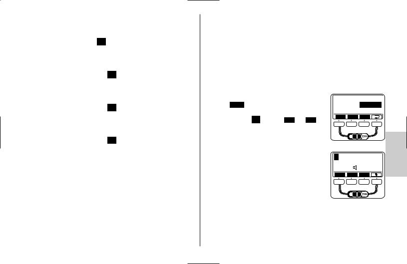
5.2 TTL flash mode
The TTL flash mode offers a very simple method of achieving excellent flash shots. In this mode, exposure readings are taken by a sensor built into the camera which measures the amount of light through the camera lens (TTL). The electronic control circuit within the camera transmits a stop signal to the flash unit after sufficient light has been emitted, instantly interrupting the flash. The advantage of this flash mode is that all factors influencing correct exposure (filters, change of aperture and focal length with zoom lenses, extensions for closeups, etc.) are automatically taken into account.
TTL flash mode is supported by all modes of camera operation (such as „P“ for fully automatic settings, „A“ for aperture priority mode, „S“ for shutter priority mode, vari or scene modes, and „M“ for manual mode).
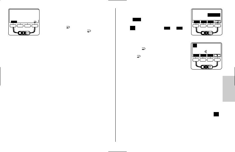
Setting procedure: |
|
Mode |
|
|
|
|
|
|
|
ATTL |
|
• Press the Mode |
button until „Mode“ flashes on the |
|
|
A |
|
|
Set |
||||
LC display. |
|
||||
|
|
|
|
||
• Set the TTL flash mode using the and |
|
|
|||
arrows. The flash mode you choose is then highligh- |
|
|
|
||
ted. |
|
|
|
|
|
The setting takes effect immediately. |
|
|
|
||
• Press the button |
to change the display back to |
TTL |
|
F 5.6 |
|
|
|
AZoom 28 |
|||
|
|
|
|
||
the normal view. |
|
7.7 m |
|
ISO 100 |
|
If the button |
is not pressed, the display will chan- |
Mode |
Para |
Sel |
|
|
|
|
|||
ge back to the normal view after about 5 seconds.
Standard TTL flash mode is only supported by cameras in Groups A, B and C.
D-TTL and I-TTL flash modes
D-TTL and I-TTL flash modes are advanced variants of the normal TTL flash
modes used with analog cameras. These modes are supported by Groups D and E cameras (see table1). Prior to shooting, the flash unit fires a series of
barely visible measuring pre-flashes. The camera evaluates the reflected preflash light so that the subsequent flash exposure is optimally adapted to the prevailing photographic situation (see your camera’s operating instructions).
When the TTL flash mode is selected from the „mode menu“, the flash unit automatically activates standard TTL, D-TTL or i-TTL flash mode, depending on the type of camera (see tables 1 and 2). After the settings are confirmed,  TTL will appear in the flash unit display for D-TTL or i-TTL flash modes.
119
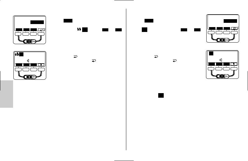
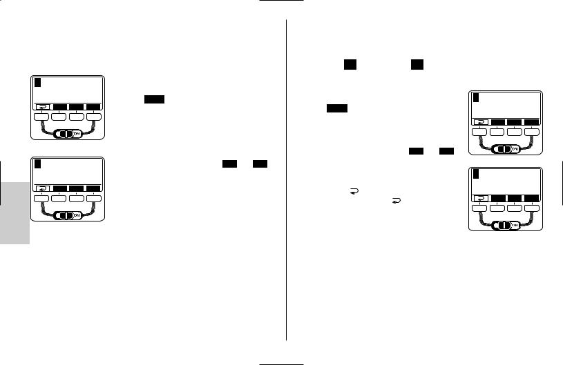
Setting procedure: |
|
|
|
Setting procedure: |
|
|
|
|
|
|
||
Mode |
|
|
|
|
|
|
|
|
Mode |
|
|
|
|
|
• Press the Mode button until „Mode“ flashes on the |
• Press the Mode |
button until „Mode“ flashes on the |
|
|
|
ATTL BL |
||||
|
|
ATTL |
|
|
|
|||||||
|
|
A |
LC display. |
|
|
LC display. |
|
|
|
|
|
A |
|
|
Set |
• Set the flash mode |
TTL using the and |
• Set the TTL BL flash mode using the and |
|
Set |
|||||
|
|
|
|
|||||||||
|
|
|
arrows. The flash mode you choose is then highligh- |
arrows. The flash mode you choose is then highligh- |
|
|
|
|||||
|
|
|
|
|
|
|
||||||
|
|
|
ted. |
|
|
ted. |
|
|
|
|
|
|
|
|
|
The setting takes effect immediately. |
The setting takes effect immediately. |
|
|
|
|
||||
TTL |
|
F 5.6 |
• Press the button |
to change the display back to |
• Press the button |
to change the display back to |
TTL |
BL |
|
F 5.6 |
||
|
|
AZoom 35 |
|
|
|
AZoom 35 |
||||||
12 m |
Para |
ISO 200 |
the normal view. If the button |
is not pressed, the |
the normal view. If the button |
is not pressed, the |
12 m |
|
ISO 200 |
|||
Mode |
Sel |
display will change back to the normal view after |
display will change back to the normal view after |
Mode |
Para |
Sel |
||||||
|
|
about 5 seconds. |
|
|
about 5 seconds. |
|
|
|
|
|||
|
|
|
|
If the shot was properly lit, the correct exposure indica- |
|
|
||||||
|
|
|
If the shot was properly lit, the correct exposure indica- |
tion will flash „OK“ for about 3 seconds (see 13). |
|
|
|
|
||||
|
|
|
tion will flash „OK“ for about 3 seconds (see 13). |
Ensure that the contre-jour light source does not shine directly into the |
||||||||
To test the TTL function with analog cameras, a roll of film has to be in the |
lens, as this will interfere with the camera’s TTL metering system. |
|||||||||||
camera. Please note whether there are limitations for your camera in Depending on the camera model, the suitable fill-in flash mode will be automa- terms of film sensitivity or ISO (i.e., maximum ISO 1000) for TTL flash tically activated after TTL BL flash mode has been set:
operation (see your camera’s operating instructions). |
Group A: |
|||||
5.3 TTL fill-in flash mode |
• Automatic fill-in flash mode or matrix-controlled fill-in flash mode |
|||||
Fill-in flash |
TTL |
BL overcomes troublesome dense shadows for daylight shots |
• Either set automatically or manually on the camera (see camera’s operating |
|||
and produces a more balanced exposure between subject and background with |
instructions) |
|||||
contre-jour shots. The camera’s computer-controlled metering system sets the |
• Display on flash unit: |
TTL |
|
|||
most suitable combination of shutter speed, aperture and flash output. When |
• No extra settings are necessary on the flash unit, nor is there any display for |
|||||
using a camera from Groups C, D and E (see table 1) with a D-AF Nikkor lens, |
||||||
this mode. |
||||||
the distance to the subject is also calculated into the optimal flash performance. |
||||||
|
|
|
||||
120
Group B:
•Matrix-controlled fill-in flash mode.
•Settings made on flash unit.
•Display on flash unit after saving: TTL BL
Group C:
•3D multi-sensor fill-in flash mode.
•Settings made on flash unit.
•Display on flash unit after saving:  TTL BL
Group D:
•D-TTL 3D flash mode.
•Settings made on flash unit.
•Display on flash unit after saving:  TTL BL
Group E:
•i-TTL BL flash mode (not with Coolpix cameras).
•Settings made on flash unit.
•Display on flash unit after saving:  TTL BL
Some cameras do not support TTL fill-in flash mode in combination with SPOT exposure metering. This flash mode will then either be automatically cancelled or cannot be activated in the first place. In this case, normal TTL flash mode, D-TTL or i-TTL modes will be set (see camera’s operating instructions).
5.4 Automatic flash mode
In the automatic flash mode A, the flash unit sensor measures the light that reflects back from the subject. The sensor has a coverage of about 25°, and only measures the light for the time a flash is fired by the mecablitz. The flash is cut off as soon as sufficient light has been emitted for correct exposure. The sensor of the mecablitz has to be directed at the subject.
The maximum range is shown on the LC display. The shortest shot distance is approximately 10% of the maximum distance range. The subject should be located within the middle third of the distance range shown on the LC display to allow the electronic system sufficient leeway for compensation.
Setting procedure:
•Press the Mode button until „Mode“ flashes on the LC display.
•Set the flash mode A using the and arrows. The flash mode selected is then highlighted. The setting takes effect immediately.
•Press the button  to change the LC display back to the normal view. If the button
  is not pressed, the display will change back to the normal view after about 5 seconds.
Mode |
TTL BL |
|
AA |
|
M |
Set |
A |
|
F 4.5 |
|
|
|
||
|
|
AZoom 70 |
|
|
14 m |
ISO 200 |
|
|
|
|
|
Mode Para |
Sel |
|
|
If the shot was properly lit, the correct exposure indication will flash „OK“ for about 3 seconds (see 13).
121
5.5 Automatic fill-in flash mode
When shooting in automatic fill-in flash mode in daylight, the automatic flash mode A will automatically set a correction of between -1 and -2 f-stops to compensate for flash exposures (see 6.4 and 10.5).
This has a graduated lightening effect on shadowy areas, which has a natural appearance on the photograph.
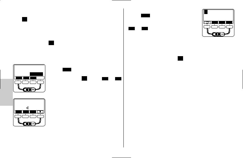
5.6 Manual flash mode
In the manual flash mode M , the flash unit emits the full uncontrolled amount of light if no partial light output has been selected. The specific photographic situation can be taken into account by making adjustments to the aperture setting or by selecting a suitable partial light setting.
Setting procedure:
Mode |
TTL BL |
|
A |
|
M |
Set 
 F 4.0M
MZoom 24
10 m |
ISO 200 |
Mode Para Sel
•Press the Mode button until „Mode“ flashes on the LC display.
• Choose the flash mode M using the and arrows. The flash mode M is then highlighted.
The setting takes effect immediately.
•Press the button  to change the LC display back to the normal view. If the button
  is not pressed, the display will change back to the normal view after about 5 seconds.
Set partial light output: |
M |
F 4.0 |
|
|
• Press the Para button (Parameters ) until „P“ flashes |
|
|||
|
MZoom 24 |
|||
|
|
|||
on the LC display for partial light output. |
0,6 m |
P1/8 |
|
|
Para |
– |
+ |
||
• Set the desired light output (1/1-1/256) with the |
||||
|
|
|
||
•Press the button  to change the LC display back to the normal view. If the button
  is not pressed,
the display will change back to the normal view after about 5 seconds.–+ and buttons. The setting takes effect imme-diately.
The mecablitz LC display will indicate the flash-to-subject distance required for a correct flash exposure.
Some cameras only support the M manual flash mode when the camera is set to the manual operating mode M.
5.7 Strobe flash mode
The strobe flash mode 

 is a manual flash mode. It allows several flash exposures to be made on a single photo, which can be especially interesting for movement studies or special effect images. In strobe flash mode, several flashes at a certain flash frequency are emitted. For this reason, this function is only possible with a partial light output of 1/4 or less.
The flash frequency (flashes per second) for a stroboscope image can be set between 1 ... 50 Hz in 1 Hz intervals, and the number of flashes can be set between 2 ... 50 in intervals of one.
122

Setting procedure:
Mode |
|
A |
|
|
M |
|
|
Set |
|
N24:f10Hz |
|
|
|
|
|
|
AZoom 24 |
1.2 m |
|
P1/32 |
Mode |
Para |
Sel |
•Press the Mode button until „Mode“ flashes on the LC display.
•Choose the flash mode 

 using the and arrows. The flash mode

 is then highlighted. The setting takes effect immediately.
•Press the button  to change the LC display back to the normal view. If the button
  is not pressed, the display will change back to the normal view after about 5 seconds.
Strobe number of flashes (N)
In strobe mode, the number of flashes per shot (N) can be selected.
The number of flashes can be set from 2 to 50 in intervals of one. The maximum manual partial light output is automatically adjusted to this number.
Strobe flash frequency (f)
Strobe mode allows you to select the flash frequency (f), which indicates the number of flashes per second. The number of flashes can be set from 2 to 50 in intervals of one. The maximum manual partial light output is automatically adjusted to this number.
Setting procedure: |
|
|
|
|
• Press the Para |
button (Parameters) until the desired |
N24 |
|
|
flash parameter (N or f) flashes on the LC display. |
|
|
||
• Set the desired value using the + |
and – but- |
2.1 m |
+ |
|
tons. The setting takes effect immediately. |
Para – |
|||
|
|
|||
• Press the button |
to change the LC display back |
|
|
|
to the normal view. If the button |
is not pressed, |
|
|
|
the display will change back to the normal view after |
|
|
||
about 5 seconds. |
|
|
|
|
The maximum possible partial light output depends on the ISO and aperture set- |
||||
tings, and is automatically set in strobe mode. If you desire short flashes, you |
||||
can manually reduce the partial light output to the lowest value of 1/256. |
|
|||
The mecablitz LC display will indicate the flash-to-subject distance required for a correct flash exposure, given the parameters selected. By changing the aperture setting or the partial light output, this value can be adjusted to fit the actual distance to the subject.
Setting procedure:
• Press the Para button (Parameters) until the desired |
|
F 4.0 |
|
flash parameter |
|
MZoom 24 |
|
(F=f-stop or P=partial light output) appears on the |
4,6 m |
P1/1 |
|
LC display. |
Para |
– |
+ |
|
|
|
|
• Set the desired value using the |
+ and – |
but- |
|
|
|
||||
tons. The setting takes effect immediately. |
|
|
||
• Press the button |
to change the LC display back to |
|
||
the normal view. If the button |
is not pressed, the |
|
||
display will change back to the normal view after |
|
|||
about 5 seconds. |
|
|
|
|
Aperture and ISO settings do not appear on the LC display in strobe mode. Strobe mode may not be combined with an operational second reflector.
2.1 m |
P1/32 |
|
Para |
– |
+ |
|
123 |
|
|
||
6 Flash parameters (Parameter menu)
For the flash unit to operate correctly, various flash parameters such as the zoom position of the main reflector, aperture, ISO light sensitivity, etc. have to be adjusted to match the camera.
When using the flash unit with cameras in Group A (see table 1), these parameters have to be set by hand.
For cameras in Groups B, C, D, or E, the flash parameters are set automatically if the camera is equipped with a CPU-capable lens and transfers the necessary data to the flash unit. For this automatic data transfer to occur, the flash unit has to be mounted on the camera, and both devices have to be switched on. In addition, a data exchange between the camera and flash unit has to be initiated, for which you simply briefly press the shutter release. The maximum range as per the current flash parameters is shown on the display.
6.1 Setting procedure for the flash parameters
When a button is pressed for the first time, the LC display is illuminated.
Depending on the flash mode set, various flash parameters are shown in the menu: For cameras with digital data transfer, the flash parameters for aperture (F), lens focal length (Zoom), and light sensitivity (ISO) are automatically set on
the flash unit. The flash parameters for aperture (F) and light sensitivity (ISO) cannot be changed.
If the camera is equipped with a non-CPU capable lens (such as a lens without autofocus), the flash parameters for aperture (F) and focal length (Zoom) have to be set manually on the flash unit.
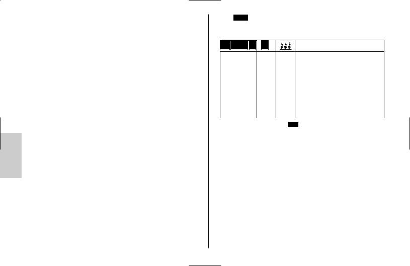
Press the Para button (Parameters) until the desired flash parameter (see below) appears on the LC display.
The following parameters are available:
TTL TTL-BL A |
M |
|
|
— |
— |
N |
Number of strobe flashe |
|
|
||||
|
|
— |
— |
f |
Strobe flash frequency |
|
|||||
|
|
|
|
|
|
|
|
||||
|
|
— |
P |
P |
Manual partial light output |
|
|||||
|
|
|
|
|
|
|
|
||||
|
|
F |
F |
F |
Aperture |
|
|||||
|
|
|
|
|
|
|
|
||||
|
|
Zoom |
Zoom |
Zoom |
Mainreflektor position |
|
|||||
|
|
|
|
|
|
|
|
||||
|
|
EV |
— |
— |
Manual flash exposure correction |
|
|||||
|
|
|
|
|
|
|
|
||||
|
|
ISO |
ISO |
ISO |
Light sensitivity |
|
|||||
|
|
|
|
|
|
|
|
|
|
|
|
• Set the desired value using the |
+ |
|
and |
|
buttons. The setting takes effect |
||||||
– |
|||||||||||
|
|
|
|||||||||
immediately. |
|
|
|
|
|
|
|
|
|
||
•Press the button  to change the LC display back to the normal view. If the button
  is not pressed, the display will change back to the normal view after about 5 seconds.
124
6.2 Aperture (F)
If there is no digital data transfer between the camera and flash unit, for example with cameras from Group A (see table 1) or when using non-CPU-capable lenses, the aperture can be manually set from 1.0 to 45 (at ISO 100), in full f- stop intervals. For flash modes A (automatic) and M (manual), the camera and flash unit have to be set to the same aperture.
Setting procedure:
A |
F 4.0 |
|
AZoom 70 |
7,7 m |
ISO 200 |
Mode Para |
Sel |
•Press the Para button (Parameters) until „F“ flashes on the LC display.
A |
F 8.0 |
|
|
AZoom 70 |
|
3,8 m |
ISO 200 |
|
Para |
– |
+ |
• Set the desired value using the + and – buttons.
The setting takes effect immediately.
|
• Press the button |
to change the LC display back |
||
to the normal view. If the button |
is not pressed, |
|||
|
||||
the display will change back to the normal view after about 5 seconds.
During digital data transfer between the camera and flash unit, intermediate values are also adjusted. During TTL flash mode, setting the aperture on the flash unit is only necessary to achieve the correct distance range indication, not for the function of the flash.
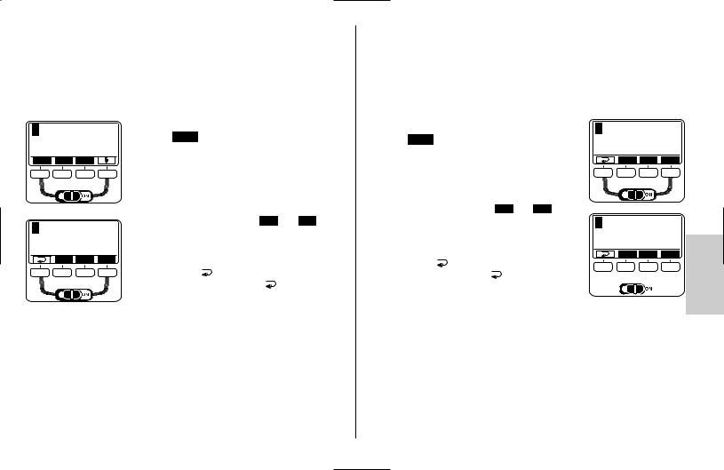
6.3 Main reflector position (Zoom)
If there is no digital data transfer between the camera and flash unit, for example with cameras from Group A (see table 1) or when using non-CPU- capable lenses, the reflector positions 24 mm - 28 mm - 35 mm - 50 mm - 70 mm -
85 mm - 105 mm (35mm format 24 x 36) can be set manually.
MZoom will then appear in the LC display.
Setting procedure:
•Press the Para button (Parameters) until „MZoom“ appears on the LC display.
• Set the desired value using the + and – buttons. The setting takes effect immediately.
A |
F 8.0 |
|
|
MZoom 35 |
|
12 m |
ISO 200 |
|
|
Para – |
+ |
A |
|
F 8.0 |
|
MZoom 70
16 m ISO 200
Para – +

During digital data transfer between the camera and flash unit, the main reflector positions are adjusted automatically.
AZoom will then appear in the LC display.
125
6.4 Flash exposure correction (EV)
Manual flash exposure correction (EV) can help offset extreme differences in contrast between the subject and background. Corrections from -3 f-stops (EV) to +3 f-stops (EV) can be made, in 1/3 increments (also see 10.5).
Setting procedure:
A |
F 8.0 |
|
|
MZoom 35 |
|
12 m |
EV 0 |
|
Para |
– |
+ |
|
F 8.0 |
|
A |
|
|
|
MZoom 35 |
|
6,1 m |
EV+2 |
|
Para |
– |
+ |
|
|
|
•Press the Para button (Parameters) until „EV“ flashes on the LC display.
• Set the desired EV value using the + and – buttons. The setting takes effect immediately.
•Press the button  to change the LC display back to the normal view. If the button
  is not pressed, the display will change back to the normal view after about 5 seconds.
6.5 Light sensitivity (ISO)
If there is no digital data transfer between the camera and flash unit, for example with cameras from Group A (see table 1) or when using non-CPU–capable lenses, the ISO can be manually set from 6 to 6400.
For flash modes A (automatic) and M (manual), the camera and flash unit have to be set to the same ISO value.
Setting procedure:
|
|
|
A |
F 8.0 |
|
|
• Press the Para |
button (Parameters) until „ISO“ flas- |
|
MZoom 35 |
|||
12 m |
ISO 200 |
|||||
hes on the LC display. |
|
|||||
|
Para |
– |
+ |
|||
|
|
|
||||
• Set the desired ISO value using the + and – |
A |
|
|
|||
buttons. |
|
|
|
|
||
The setting takes effect immediately. |
F 8.0 |
|
||||
|
|
|
|
MZoom 35 |
||
• Press the button |
to change the LC display back to |
17 m |
ISO 400 |
|||
the normal view. If the button |
is not pressed, the |
Para |
– |
+ |
||
|
|
|
||||
display will change back to the normal view after |
|
|
|
|||
about 5 seconds. |
|
|
|
|
||
During TTL flash mode, setting the ISO on the flash unit is only necessary to achieve the correct distance range indication, not for the function of the flash.
126
 Loading...