

Page 1
IC equipment
IC equipment: Liquid Handling Station (6.5330.130)
Manual
8.110.8030EN / 2014-03-24
Page 2

Page 3

Metrohm AG
CH-9100 Herisau
Switzerland
Phone +41 71 353 85 85
Fax +41 71 353 89 01
info@metrohm.com
www.metrohm.com
IC equipment
IC equipment: Liquid Handling Sta-
tion (6.5330.130)
8.110.8030EN / 2014-03-24
Manual
zst
Page 4

Teachware
Metrohm AG
CH-9100 Herisau
teachware@metrohm.com
This documentation is protected by copyright. All rights reserved.
Although all the information given in this documentation has been
checked with great care, errors cannot be entirely excluded. Should you
notice any mistakes please send us your comments using the address
given above.
Documentation in additional languages can be found on
http://documents.metrohm.com.
Page 5

■■■■■■■■■■■■■■■■■■■■■■
Table of contents
1 Introduction 1
1.1 Description ............................................................................ 1
1.2 About the documentation ................................................... 1
1.2.1 Symbols and conventions ........................................................ 2
2 Overview 3
2.1 Parts of the IC equipment: Liquid Handling Station .......... 3
2.2 Parts of the Liquid Handling Station .................................. 4
3 Installation 5
3.1 Installing the Liquid Handling Station ................................ 5
3.2 Installing the rinsing solution flow path ............................ 5
Table of contents
4 Operation and maintenance 11
4.1 Replacing the pump tubing ............................................... 11
5 Technical specifications 12
5.1 Liquid Handling Station (6.2841.120) .............................. 12
6 Accessories 13
Index 15
IC equipment: Liquid Handling Station
■■■■■■■■
III
Page 6

Table of figures
Table of figures
Figure 1 IC equipment: Liquid Handling Station – Parts ................................... 3
Figure 2 Liquid Handling Station – Parts .......................................................... 4
■■■■■■■■■■■■■■■■■■■■■■
■■■■■■■■
IV
IC equipment: Liquid Handling Station
Page 7
■■■■■■■■■■■■■■■■■■■■■■
1 Introduction
1.1 Description
The IC equipment: Liquid Handling Station is used for rinsing the sample
needle after sample aspiration.
The sample needle is rinsed with ultrapure water in the rinsing unit of the
Liquid Handling Station (6.2841.120) after each sample aspiration.
The IC equipment: Liquid Handling Station can be mounted on any Sample Processor equipped with a Swing Head and a peristaltic pump.
A trap column is installed between the supply bottle and the peristaltic
pump to ensure that the rinsing solution is free of ionic contamination.
1.2 About the documentation
1 Introduction
This manual describes the installation of the IC equipment: Liquid Handling Station and the connection of the capillary connections between the
supply bottle, the trap column, the peristaltic pump and the Liquid Handling Station.
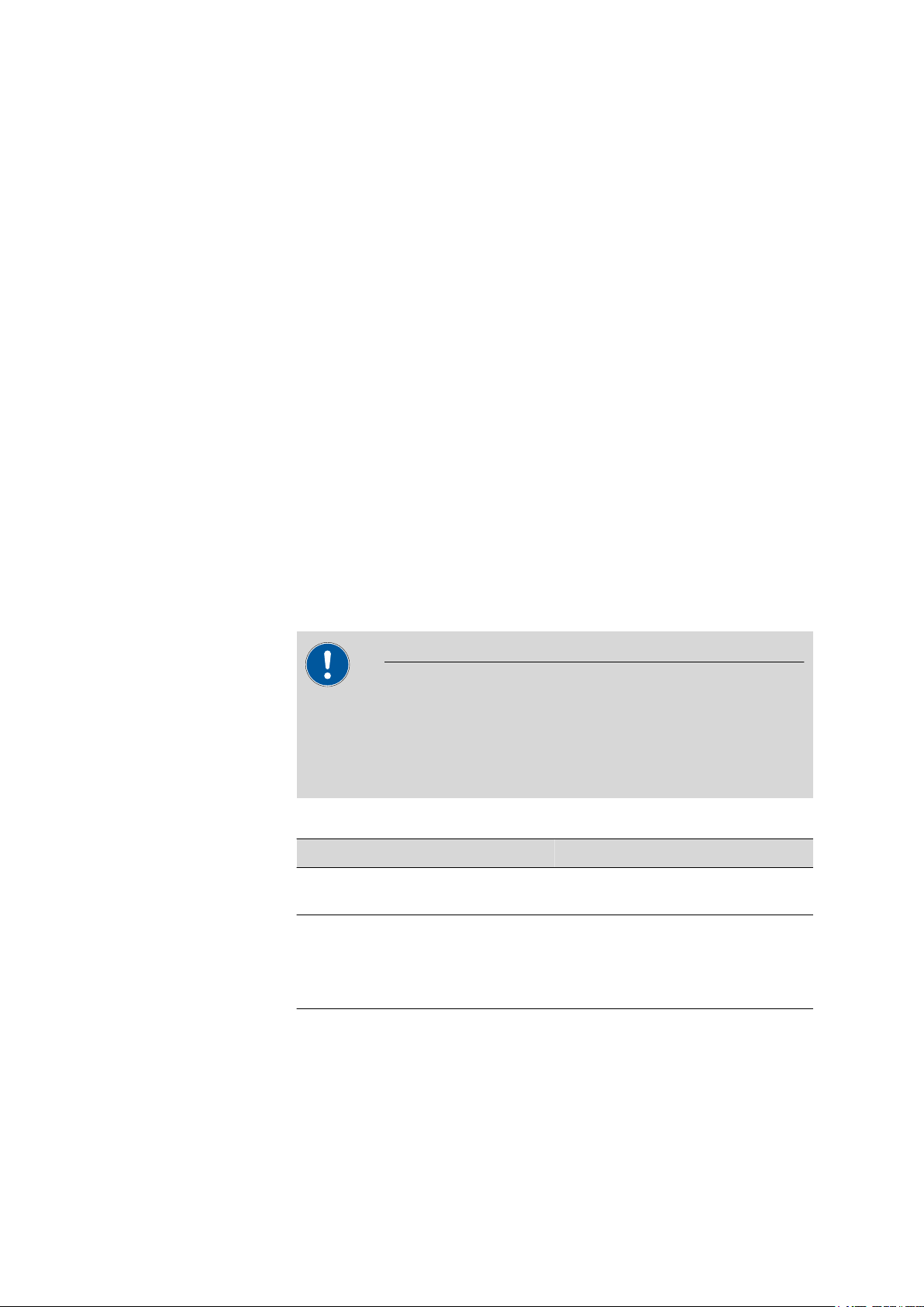
CAUTION
Please read through this documentation carefully before putting the
equipment into operation. The documentation contains information
and warnings which the user must follow in order to ensure safe operation of the equipment.
Additional documentation
Topic Document
Mounting the Liquid Handling Station on
the Sample Processor
Installing the peristaltic pump and the
respective tubing
Care and maintenance of the pump tubing
Manual for the Liquid Handling Station
Manual for the Sample Processor
IC equipment: Liquid Handling Station
■■■■■■■■
1
Page 8

1.2 About the documentation
1.2.1 Symbols and conventions
The following symbols and formatting may appear in this documentation:
Method Dialog text, parameter in the software
File ▶ New Menu or menu item
[Next] Button or key
■■■■■■■■■■■■■■■■■■■■■■
Cross-reference to figure legend
The first number refers to the figure number, the second to the instrument part in the figure.
Instruction step
Carry out these steps in the sequence shown.
WARNING
This symbol draws attention to a possible life-threatening hazard or risk of injury.
WARNING
This symbol draws attention to a possible hazard due
to electrical current.
WARNING
This symbol draws attention to a possible hazard due
to heat or hot instrument parts.
WARNING
This symbol draws attention to a possible biological
hazard.
CAUTION
This symbol draws attention to possible damage to
instruments or instrument parts.
NOTE
This symbol highlights additional information and
tips.
■■■■■■■■
2
IC equipment: Liquid Handling Station
Page 9

■■■■■■■■■■■■■■■■■■■■■■
2 Overview
2 Overview
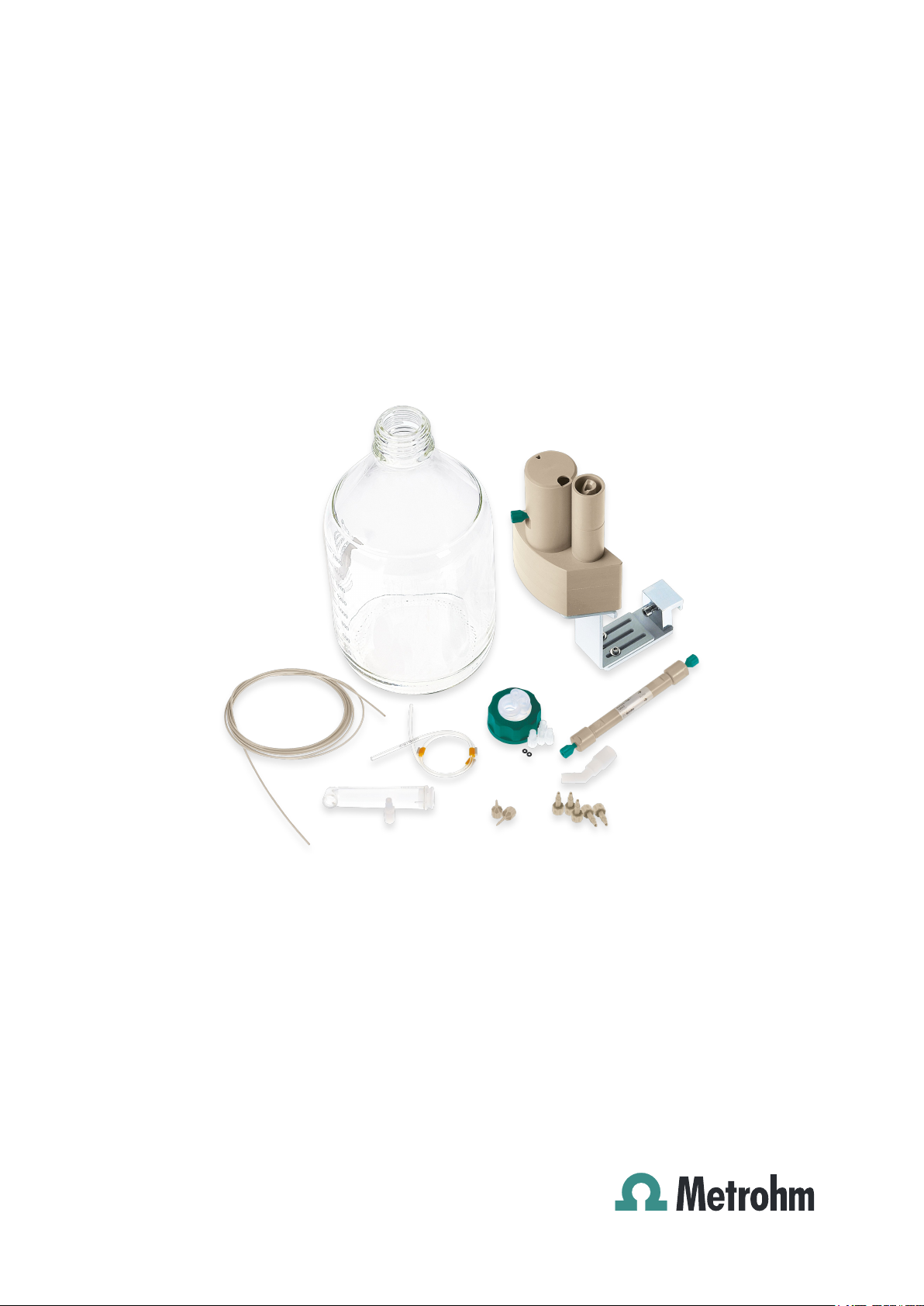
2.1 Parts of the IC equipment: Liquid Handling Station
Figure 1 IC equipment: Liquid Handling Station – Parts
IC equipment: Liquid Handling Station
■■■■■■■■
3
Page 10

2.2 Parts of the Liquid Handling Station
2.2 Parts of the Liquid Handling Station
■■■■■■■■■■■■■■■■■■■■■■
Cover
1
For the mixing vessel.
Main body
3
With magnetic stirrer dummy.
Clamping fastener
5
Support bracket
7
Waste connector
9
Mixing vessel
11
Figure 2 Liquid Handling Station – Parts
Rinsing unit
2
Rinsing unit inlet
4
Sealed with threaded stopper.
Base plate
6
Cable clip
8
Mixing vessel outlet
10
Sealed with threaded stopper.
■■■■■■■■
4
IC equipment: Liquid Handling Station
Page 11

■■■■■■■■■■■■■■■■■■■■■■
3 Installation
3.1 Installing the Liquid Handling Station
The Liquid Handling Station forms part of the IC equipment: Liquid Handling Station.
1
Installing the Liquid Handling Station
Install the Liquid Handling Station on the left side of the Sample Processor (see manual for the Liquid Handling Station).
3.2 Installing the rinsing solution flow path
The Sample Processor's peristaltic pump transfers ultrapure water to the
Liquid Handling Station's rinsing unit. In the rinsing unit, the Sample Processor needle is cleaned after each sample aspiration.
3 Installation
Required accessories
We recommend that you install the Metrosep I Trap 1 - 100/4.0
(6.1014.200) column between the supply bottle and the peristaltic pump.
This trap column removes ionic contamination from the ultrapure water.
Preparing the supply bottle
■ Clear glass bottle (6.1608.070)
■ PEEK capillary (6.1831.180)
■ Bottle cap (6.1602.160) with O-ring, M6 tubing nipple and M8 stopper
■ Adapter for adsorber tube (6.1624.000)
■ Adsorber tube (6.1619.000)
■ Capillary cutter (6.2621.080)
■ Fill the clear glass bottle with ultrapure water.
1
IC equipment: Liquid Handling Station
■■■■■■■■
5
Page 12

3.2 Installing the rinsing solution flow path
■ Cut off a piece of the capillary that is approx. 50 cm long using
2
3
Threading the capillary through the bottle holder
■ Push one end of the capillary (50 cm) through the M6 tubing nip-
■ Loosely secure the capillary in place using the tubing nipple.
4
Mounting the bottle cap to the supply bottle
■■■■■■■■■■■■■■■■■■■■■■
the capillary cutter.
ple (1), the O-ring (2) and the M6 opening of the bottle cap (3)
and into the bottle.
■■■■■■■■
6
■ Screw the bottle cap onto the supply bottle.
IC equipment: Liquid Handling Station
Page 13

■■■■■■■■■■■■■■■■■■■■■■
5
Setting the capillary to the correct length
■ Push the capillary far enough into the bottle that it reaches the
bottom of the bottle.
■ Tighten the tubing nipple.
The capillary is secured.
6
Inserting the stopper
3 Installation
7
IC equipment: Liquid Handling Station
■ Screw the M8 stopper into the M8 opening of the bottle cap.
Filling the adsorber tube
Fill the adsorber tube as follows:
■ some cotton
■ CO
■ some cotton
adsorber material
2
Seal the adsorber tube with the stopper.
■■■■■■■■
7
Page 14

3.2 Installing the rinsing solution flow path
8
Inserting the adsorber tube
■ Insert the adapter into the SGJ opening of the bottle cap.
■ Screw the adsorber tube into the upper opening of the adapter.
Installing the capillary between the supply bottle and the
trap column
■■■■■■■■■■■■■■■■■■■■■■
Required accessories
■ PEEK capillary (6.1831.180)
■ Metrosep I Trap 1 - 100/4.0 (6.1014.200)
■ Pressure screw (6.2744.010)
1
Removing the stoppers
■ Remove the stoppers from the trap column's inlet and outlet.
Keep the stoppers.
2
Installing the capillary to the column inlet
■ Tighten the other end of the installed capillary to the trap column
inlet using a pressure screw.
■■■■■■■■
8
IC equipment: Liquid Handling Station
Page 15

■■■■■■■■■■■■■■■■■■■■■■
Installing the capillary between the trap column and the
peristaltic pump
Required accessories ■ PEEK capillary (6.1831.180)
■ Pressure screw (6.2744.010)
■ Pump tubing with yellow stoppers (6.1823.390)
■ Coupling olive/UNF 10/32 (6.2744.034)
■ Capillary cutter (6.2621.080)
3 Installation
1
Preparing the pump tubing
■ Attach a coupling olive/UNF 10/32 (6.2744.034) to each end of
the pump tubing.
(See the chapter "Installing the peristaltic pump" in the manual
for the Sample Processor.)
2
Cutting the capillary to size
■ Cut off a piece of approx. 70 cm from the long capillary using the
capillary cutter.
3
Mounting the capillary
■ Tighten one end of the capillary to the trap column outlet using a
pressure screw.
■ Tighten the other end of the capillary to the pump tubing inlet
using a pressure screw.
Installing the capillary between the peristaltic pump and
the Liquid Handling Station
Required accessories
IC equipment: Liquid Handling Station
■ PEEK capillary (6.1831.180)
■ Pressure screw (6.2744.010)
■ Pump tubing with yellow stoppers (6.1823.390)
■ Liquid Handling Station (6.2841.120)
■■■■■■■■
9
Page 16

3.2 Installing the rinsing solution flow path
■ Capillary cutter (6.2621.080)
1
Cutting the capillary to size
■ Cut off a piece of approx. 60 cm from the long capillary using the
2
Mounting the capillary
■ Tighten one end of the capillary to the pump tubing outlet using a
■ Tighten the other end of the capillary to the rinsing unit inlet (2-4)
■■■■■■■■■■■■■■■■■■■■■■
capillary cutter.
pressure screw (6.2744.010).
using a pressure screw (6.2744.010).
Completing the installation
1
Mounting the drainage tubing
Use the PVC tubing from the accessories for the Liquid Handling Station as drainage tubing.
■ Push one end of the PVC tubing over the waste connector (2-9)
of the rinsing unit.
■ Guide the other end of the PVC tubing to the waste container.
2
Installing the peristaltic pump
■ Insert the pump tubing in the tubing cartridge (see manual for
the Sample Processor).
■ Insert the tubing cartridge in the cartridge holder (see manual for
the Sample Processor).
3
Placing the supply bottle
■ Place the supply bottle next to the Sample Processor.
■■■■■■■■
10
IC equipment: Liquid Handling Station
Page 17

■■■■■■■■■■■■■■■■■■■■■■
4 Operation and maintenance
4.1 Replacing the pump tubing
Pieces of pump tubing inserted into the peristaltic pump are consumables
with a limited service life.
Pieces of pump tubing with 3 stoppers are tensioned in the tubing cartridge so that they end up positioned between two stoppers. This results
in two possible positions for the tubing cartridge. Once the pump tubing
exhibits significant signs of wear, it can be tensioned a second time in the
other respective position.
4 Operation and maintenance
Maintenance interval
Replace the pump tubing every 2 months.
Replace the pump tubing every 4 weeks if the peristaltic pump is being
used continuously.
IC equipment: Liquid Handling Station
■■■■■■■■
11
Page 18

5.1 Liquid Handling Station (6.2841.120)
5 Technical specifications
5.1 Liquid Handling Station (6.2841.120)
Information on the technical specifications of the Liquid Handling Station
can be found in the manual for the Liquid Handling Station.
■■■■■■■■■■■■■■■■■■■■■■
■■■■■■■■
12
IC equipment: Liquid Handling Station
Page 19

■■■■■■■■■■■■■■■■■■■■■■
6 Accessories
Up-to-date information on the scope of delivery and optional accessories
for your instrument can be found on the Internet.
When you receive your new instrument, we recommend downloading
the accessories list from the Internet, printing it out and keeping it
together with the manual for reference purposes.
Instruments currently sold
If you do not know the article number of your instrument, proceed as follows:
Downloading the accessories list
6 Accessories
NOTE
Go to the Metrohm website http://www.metrohm.com/com.
1
2
Click on .
The Search webpage will be displayed.
Enter a search term relating to the instrument into the search field
3
and click on Find.
The search results will be displayed.
In the search results, select the Devices tab (if it is not already
4
selected) and then click on the Metrohm article number of the
required instrument (e.g. 2.852.0050).
The page with information pertaining to the searched article is displayed.
Select the Parts tab.
5
The complete list of accessories with the scope of delivery and the
optional accessories will be displayed.
6
Click on .
IC equipment: Liquid Handling Station
■■■■■■■■
13
Page 20

■■■■■■■■■■■■■■■■■■■■■■
The Partslists webpage will be displayed.
Select the desired output language.
7
With the article number entered, click on the command Generate
8
PDF.
The PDF file with the accessories data will be created in the language
selected.
Direct access for all instruments
If you are unable to find your instrument using the search as described
above, this may be due to the instrument not being sold anymore. Using
the article number, you can download accessories lists for all instruments
as follows:
Downloading the accessories list
Type http://partslists.metrohm.com into your Internet browser.
1
The Partslists webpage will be displayed.
Select the desired output language.
2
Enter the article number and click on the Generate PDF command.
3
The PDF file with the accessories data will be created in the language
selected.
■■■■■■■■
14
IC equipment: Liquid Handling Station
Page 21

■■■■■■■■■■■■■■■■■■■■■■
Index
Index
I
Installation ................................. 5
L
Liquid Handling Station
Install ................................... 5
IC equipment: Liquid Handling Station
■■■■■■■■
15
 Loading...