

Page 1
IC equipment
IC equipment: Dialysis (6.5330.100)
Manual
8.110.8028EN / 2014-02-20
Page 2

Page 3

Metrohm AG
CH-9100 Herisau
Switzerland
Phone +41 71 353 85 85
Fax +41 71 353 89 01
info@metrohm.com
www.metrohm.com
IC equipment
IC equipment: Dialysis (6.5330.100)
8.110.8028EN / 2014-02-20
Manual
zst
Page 4

Teachware
Metrohm AG
CH-9100 Herisau
teachware@metrohm.com
This documentation is protected by copyright. All rights reserved.
Although all the information given in this documentation has been
checked with great care, errors cannot be entirely excluded. Should you
notice any mistakes please send us your comments using the address
given above.
Documentation in additional languages can be found on
http://documents.metrohm.com.
Page 5

■■■■■■■■■■■■■■■■■■■■■■
Table of contents
1 Introduction 1
1.1 Description of the IC equipment: Dialysis .......................... 1
1.2 About the documentation ................................................... 1
1.3 Symbols and conventions .................................................... 2
2 Overview 3
2.1 Parts of the IC equipment: Dialysis ..................................... 3
2.2 Parts of the dialysis cell ....................................................... 4
2.3 Dialysis cell connectors ........................................................ 4
2.4 Mode of operation for dialysis ............................................ 5
3 Installation 6
Table of contents
3.1 Preparing the dialysis cell .................................................... 6
3.2 Connecting the dialysis cell ............................................... 10
3.3 Inserting the dialysis cell .................................................... 14
3.4 Conditioning the dialysis system ....................................... 15
4 Operation and maintenance 16
4.1 Operation ............................................................................ 16
4.1.1 Optimizing the dialysis ........................................................... 16
4.1.2 Recommended procedure for the dialysis ............................... 18
4.2 Maintenance ....................................................................... 20
5 Technical specifications 21
5.1 Dialysis cell (6.2729.100) ................................................... 21
5.2 Dialysis membrane (6.2714.010) ....................................... 21
5.3 Dialysis membrane (6.2714.030) ....................................... 21
6 Accessories 22
Index 24
IC equipment: Dialysis
■■■■■■■■
III
Page 6

Table of figures
Table of figures
Figure 1 IC equipment: Dialysis – Parts ............................................................ 3
Figure 2 Dialysis cell – Parts ............................................................................. 4
Figure 3 Dialysis cell – Connectors ................................................................... 4
Figure 4 Stopped-flow dialysis ......................................................................... 5
Figure 5 Area / transfer time diagram ............................................................ 17
■■■■■■■■■■■■■■■■■■■■■■
■■■■■■■■
IV
IC equipment: Dialysis
Page 7

■■■■■■■■■■■■■■■■■■■■■■
1 Introduction
1.1 Description of the IC equipment: Dialysis
The IC equipment: Dialysis (6.5330.100) contains all accessories required
for inline dialysis of matrix-contaminated samples (e.g. emulsions, samples
containing fat and protein, body fluids or waste waters with high pollution loads) directly before injection.
The main component of the IC equipment: Dialysis is the high-performance dialysis cell. The ions travel through the semipermeable membrane,
diffusing out of the flowing sample and into the stationary acceptor solution, where they are preconcentrated. The ion-preconcentrated acceptor
solution is then subsequently injected directly into the IC system.
To operate the dialysis cell, you need an IC system with a peristaltic pump
and a cell holder as well as a Sample Processor with a peristaltic pump.
1 Introduction
1.2 About the documentation
This manual describes the correct assembly and maintenance of the IC
equipment: Dialysis as well as the installation of the capillary connections
to and from the dialysis cell. In addition, it describes how the dialysis
works and provides information on applying and optimizing the dialysis.
The installation of the peristaltic pump is not described in this manual. This
description can be found in the respective manuals for the ion chromatograph or the Sample Processor.
CAUTION
Please read through this documentation carefully before putting the IC
equipment: Dialysis into operation. The documentation contains information and warnings which the user must follow in order to ensure
safe operation of the IC equipment: Dialysis.
IC equipment: Dialysis
■■■■■■■■
1
Page 8
1.3 Symbols and conventions
1.3 Symbols and conventions
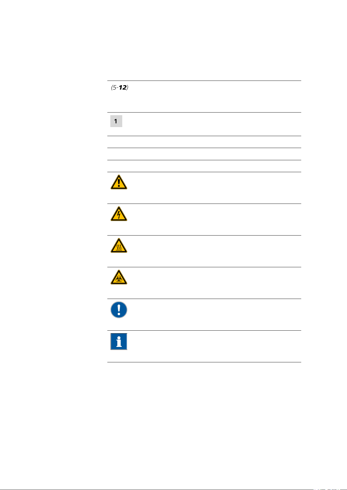
The following symbols and formatting may appear in this documentation:
Cross-reference to figure legend
The first number refers to the figure number, the second to the instrument part in the figure.
Instruction step
Carry out these steps in the sequence shown.
Method Dialog text, parameter in the software
File ▶ New Menu or menu item
[Next] Button or key
WARNING
This symbol draws attention to a possible life-threatening hazard or risk of injury.
■■■■■■■■■■■■■■■■■■■■■■
WARNING
This symbol draws attention to a possible hazard due
to electrical current.
WARNING
This symbol draws attention to a possible hazard due
to heat or hot instrument parts.
WARNING
This symbol draws attention to a possible biological
hazard.
CAUTION
This symbol draws attention to possible damage to
instruments or instrument parts.
NOTE
This symbol highlights additional information and
tips.
■■■■■■■■
2
IC equipment: Dialysis
Page 9
■■■■■■■■■■■■■■■■■■■■■■
2 Overview
2.1 Parts of the IC equipment: Dialysis
2 Overview
IC equipment: Dialysis
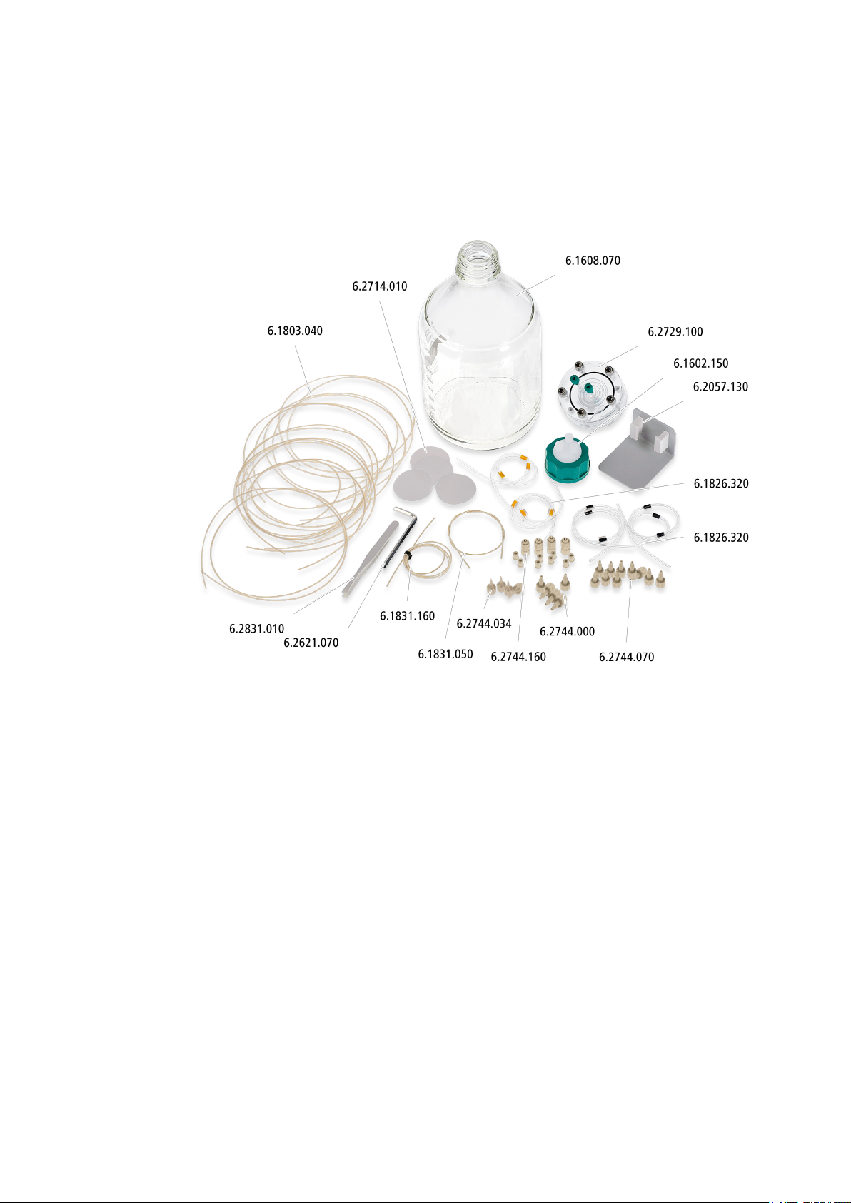
Figure 1 IC equipment: Dialysis – Parts
■■■■■■■■
3
Page 10

2.2 Parts of the dialysis cell
2.2 Parts of the dialysis cell
Figure 2 Dialysis cell – Parts
■■■■■■■■■■■■■■■■■■■■■■
Stoppers
1
Sealing ring
3
Washers
5
2.3 Dialysis cell connectors
Figure 3
Dialysis cell – Connectors
Left chamber
2
Right chamber
4
Screws
6
For joining the right and the left chamber.
1
3
5
■■■■■■■■
4
Left chamber
Outlet – Sample
Inlet – Acceptor solution
Right chamber
2
Inlet – Sample
4
Outlet – Acceptor solution
6
IC equipment: Dialysis
Page 11

■■■■■■■■■■■■■■■■■■■■■■
2.4 Mode of operation for dialysis
2 Overview
Figure 4 Stopped-flow dialysis
Sample is delivered continuously on the sample side of the dialysis cell.
After a rinsing phase, the acceptor flow is stopped. Because of the concentration gradient, the ions pass through the membrane. The acceptor
flow remains stationary until a concentration equilibrium is achieved
between the two cell halves. The concentration in the acceptor solution
thus matches the concentration of the original sample. Afterwards, the
acceptor solution is injected directly into the ion chromatograph.
IC equipment: Dialysis
■■■■■■■■
5
Page 12

3.1 Preparing the dialysis cell
3 Installation
This chapter describes the assembly and connection of the dialysis cell and
the conditioning of the dialysis system.
Depending on the ion chromatograph, the dialysis cell may be placed at
different locations. Please observe the following recommendations:
■ If you are working with an ion chromatograph that has a peristaltic
pump and a cell holder, then place the dialysis cell in the cell holder.
■ If you are working with an ion chromatograph that has a peristaltic
pump but no cell holder, then place the dialysis cell holder
(6.2057.130) in the detector chamber of your ion chromatograph.
3.1 Preparing the dialysis cell
■■■■■■■■■■■■■■■■■■■■■■
Required tools
■ Dialysis cell (6.2729.100)
■ Dialysis membrane (6.2714.010)
■ Hex key (6.2621.070)
■ Tweezers (6.2831.010)
1
Removing the stoppers
■ Remove the four green stoppers.
■ Turn the dialysis cell around and place it on a table.
The screws face upwards.
2
Removing the screws
■■■■■■■■
6
IC equipment: Dialysis
Page 13

■■■■■■■■■■■■■■■■■■■■■■
■ Loosen the screws with the hex key.
■ Remove the screws with the washers and put them aside.
3
Disassembling the dialysis cell
■ Remove the upper part of the dialysis cell.
■ Remove the sealing ring.
4
Cleaning the dialysis cell
3 Installation
CAUTION
Damage to the dialysis cell
Organic solvents (e.g.: acetone) corrode and damage the dialysis
cell material (PMMA).
■ Use only ultrapure water or a water-ethanol mixture (70:30) for
cleaning the dialysis cell.
■ For samples that contain organic components (e.g. solvents),
use the PEEK dialysis cell (6.2729.120). This cell has an excellent
chemical resistance to organic chemicals.
■ Thoroughly rinse off the sealing ring (2-3), the left chamber (2-2)
and the right chamber (2-4) of the dialysis cell with ultrapure
water.
■ Dry all parts with a lint-free cloth.
IC equipment: Dialysis
■■■■■■■■
7
Page 14

3.1 Preparing the dialysis cell
■■■■■■■■■■■■■■■■■■■■■■
5
Wetting the dialysis membrane
NOTE
In the package containing the dialysis membranes, you will find
sheets of different thicknesses and colors:
■ The firm white cardboard is a cover protecting the filtration
membranes. Don not place it in the dialysis cell.
■ The thin light-blue sheets are separation sheets placed between
two filtration membranes. Do not place them in the dialysis
cell.
■ The thin white sheets are the dialysis membranes. Use only
these for dialysis.
■ Using the tweezers, take a new dialysis membrane out of the
package.
■ Place the dialysis membrane in a petri dish filled with ultrapure
water and allow to hydrate for approx. two minutes.
6
Inserting the dialysis membrane
NOTE
Make sure that the water-soaked dialysis membrane does not dry
out before it is inserted, as it can otherwise no longer be used.
■■■■■■■■
8
■ Place the sealing ring back in the recess.
IC equipment: Dialysis
Page 15

■■■■■■■■■■■■■■■■■■■■■■
3 Installation
■ Using the tweezers, place the wet dialysis membrane centrally
inside the sealing ring onto the cell.
7
Assembling the dialysis cell
■ Place the upper part of the dialysis cell on the bottom part in such
a way that the two guide bolts fit exactly into the two bore holes.
8
Screwing the dialysis cell together
IC equipment: Dialysis
■ Screw the five screws with the washers in the dialysis cell by hand
first.
■ Then firmly tighten them with the hex key in crosswise sequence.
■■■■■■■■
9
Page 16

3.2 Connecting the dialysis cell
3.2 Connecting the dialysis cell
This chapter describes how to establish the capillary connections of the
dialysis system. It does not, however, describe the tubing configuration for
the peristaltic pump. Please refer to the chapter "Installing the peristaltic
pump" in the manual for the Sample Processor or the ion chromatograph
for this information.
■■■■■■■■■■■■■■■■■■■■■■
Required accessories
■■■■■■■■
10
Connections for acceptor solution
■ Dialysis cell (6.2729.100)
■ PTFE capillary, 0.5 mm ID / 1 m (6.1803.040)
■ Pump tubing LFL (orange/yellow), 3 stoppers (6.1826.320)
■ Pump tubing LFL (black/black), 3 stoppers (6.1826.340)
■ PEEK capillary, 0.5 mm ID / 40 cm (6.1831.050)
■ PEEK capillary, 0.5 mm ID / 70 cm (6.1831.160)
■ Pressure screw PVDF (6.2744.000)
■ Coupling olive/UNF 10/32 (6.2744.030)
■ Pressure screw, short (6.2744.070)
■ Pump tubing connection with locking nut (6.2744.160)
We recommend using the peristaltic pump in the ion chromatograph for
conveying the acceptor solution.
IC equipment: Dialysis
Page 17

■■■■■■■■■■■■■■■■■■■■■■
3 Installation
The acceptor solution is pumped with two pump tubings with yellow/
orange stoppers (6.1826.320). Additional information on the tubing configuration of the peristaltic pump can be found in the chapter "Installing
the peristaltic pump" in the manual for your ion chromatograph.
1
Preparing two pump tubings for the sample
Use the two pump tubings with black stoppers (6.1826.340) for conveying the sample. Proceed as follows for each tubing:
■ Attach the coupling olive/UNF 10/32 (6.2744.034) to the inlet.
■ Attach the pump tubing connection with locking nut
(6.2744.160) to the outlet (see chapter "Installing the peristaltic
pump" in the manual for the ion chromatograph or in the manual for the Sample Processor).
2
Preparing two pump tubings for the acceptor solution
Use the two pump tubings with orange/yellow stoppers (6.1826.320)
for conveying the acceptor solution. Proceed as follows for each tubing:
■ Attach the coupling olive/UNF 10/32 (6.2744.034) to the inlet.
■ Attach the pump tubing connection with locking nut
(6.2744.160) to the outlet (see chapter "Installing the peristaltic
pump" in the manual for the ion chromatograph or in the manual for the Sample Processor).
3
Connecting the sample inlet
■ Tighten the PEEK capillary, 0.5 mm ID / 70 cm (6.1831.160), to
the inlet of the pump tubing with black stoppers (6.1826.340)
using a pressure screw (6.2744.070).
Connect the other end of the PEEK capillary to the needle of the
Sample Processor (see manual for the Sample Processor).
IC equipment: Dialysis
■■■■■■■■
11
Page 18

3.2 Connecting the dialysis cell
■■■■■■■■■■■■■■■■■■■■■■
■ Tighten a PTFE capillary, 0.5 mm ID / 1 m (6.1803.040), to the
outlet of the pump tubing with black stoppers (6.1826.340) using
a pressure screw (6.2744.070).
Tighten the other end of the PTFE capillary to the sample inlet of
the dialysis cell (3-4) using a pressure screw (6.2744.000).
4
Connecting the sample outlet
■ Tighten a PTFE capillary, 0.5 mm ID / 1 m (6.1803.040), to the
sample outlet of the dialysis cell (3-3) using a pressure screw
(6.2744.000).
Tighten the other end of the PTFE capillary to the inlet of the second pump tubing with black stoppers (6.1826.340) using a pressure screw (6.2744.070).
■ Tighten another PTFE capillary, 0.5 mm ID / 1 m (6.1803.040), to
the outlet of the second pump tubing with black stoppers
(6.1826.340) using a pressure screw (6.2744.070).
Tighten the other end of the PTFE capillary to the waste container.
5
Connecting the inlet of the acceptor solution
■■■■■■■■
12
IC equipment: Dialysis
Page 19

■■■■■■■■■■■■■■■■■■■■■■
■ Tighten a PTFE capillary (6.1803.040) to the inlet of the pump
tubing with orange/yellow stoppers (6.1826.320) using a pressure
screw (6.2744.070).
Immerse the other end of the PTFE capillary in the vessel containing the acceptor solution (6.1808.070 with 6.1602.150) and fasten with a PVDF pressure screw (6.2744.000).
■ Tighten another PTFE capillary (6.1803.040) to the outlet of the
pump tubing with orange/yellow stoppers using a pressure screw
(6.2744.070).
Tighten the other end of the PTFE capillary to the acceptor inlet of
the dialysis cell (3-5) using a pressure screw (6.2744.000).
6
Connecting the outlet of the acceptor solution
3 Installation
IC equipment: Dialysis
■ Tighten the PEEK capillary, 0.5 mm ID / 40 cm (6.1831.050), to
the acceptor outlet of the dialysis cell (3-6) using a pressure screw
(6.2744.000).
Tighten the other end of the PEEK capillary to the sample inlet of
the injection valve (Port 1) using a pressure screw (6.2744.010).
■ Tighten a PTFE capillary, 0.5 mm ID / 1 m (6.1803.040), to the
sample outlet of the injection valve (Port 2) using a pressure screw
(6.2744.010).
Tighten the other end of the PTFE capillary to the inlet of the second pump tubing with orange/yellow stoppers (6.1826.320) using
a pressure screw (6.2744.070).
■ Tighten another PTFE capillary, 0.5 mm ID / 1 mm (6.1803.040),
to the outlet of the second pump tubing with orange/yellow stoppers (6.1826.320) using a pressure screw (6.2744.070).
Tighten the other end of the PTFE capillary to the waste container.
■■■■■■■■
13
Page 20

3.3 Inserting the dialysis cell
3.3 Inserting the dialysis cell
Inserting the dialysis cell into the ion chromatograph
1
■ Insert the dialysis cell into the cell holder provided for this pur-
pose.
■■■■■■■■■■■■■■■■■■■■■■
Inserting the dialysis cell into the cell holder
If the ion chromatograph is not equipped with a cell holder, then the dialysis cell with the dialysis cell holder (6.2057.130) has to be used.
1
■ Insert the dialysis cell into the dialysis cell holder (6.2057.130).
■ Insert the dialysis cell with the dialysis cell holder into the detector
chamber of the ion chromatograph.
■■■■■■■■
14
IC equipment: Dialysis
Page 21

■■■■■■■■■■■■■■■■■■■■■■
3.4 Conditioning the dialysis system
Prior to the first analysis, the dialysis cell with dialysis membrane in place
and all capillaries must be rinsed with ultrapure water.
1
Setting the injection valve
Set the injection valve to the FILL position in the software.
2
Putting both peristaltic pumps into operation
■ Immerse the aspiration capillary in the acceptor solution
(degassed ultrapure water).
■ Use the software to switch on both peristaltic pumps.
■ Adjust the contact pressure on both peristaltic pumps (see the
chapter "Installing the peristaltic pump" in the manual for the
ion chromatograph or the Sample Processor).
3
Conditioning the dialysis system
■ Rinse the dialysis system with ultrapure water for 20 min.
■ Check whether equal amounts of solution are emerging from
both feed lines to the waste container.
■ Check whether all capillary connections are tight.
If liquid is escaping somewhere, then tighten the corresponding
connection or redo the connection.
■ Check whether any air bubbles remain trapped in the dialysis cell.
If air bubbles are trapped in the cell, then unscrew the PEEK capillary and the PTFE capillary, (3-3) and (3-6), from the outlets of the
dialysis cell and wait until the air bubbles have escaped. Afterwards, tighten the capillaries to the dialysis cell again.
3 Installation
IC equipment: Dialysis
■■■■■■■■
15
Page 22

4.1 Operation
4 Operation and maintenance
4.1 Operation
4.1.1 Optimizing the dialysis
Determining the rinsing time
A rinsing time of two minutes is usually sufficient for completely rinsing
the sample and the acceptor channel. If necessary, this time can be
extended.
Determining the transfer time
The time for the transfer of the preconcentrated acceptor solution into the
sample loop must be chosen in such a way that the part of the acceptor
solution with the highest ion concentration will be transferred into the
sample loop.
■■■■■■■■■■■■■■■■■■■■■■
The optimum transfer time should be determined for each analysis problem on the basis of measurements of the individual ion concentrations in
relation to the transfer time and periodically verified.
1
Initial measurement
■ Set the following values in the software:
– Transfer time: 15 s
– Dialysis time: 10 min
■ Immerse the sample aspiration capillary in a standard solution
with 10 mg/L of the desired anion or cation.
■ Start the determination with the appropriate method in the soft-
ware and wait until the chromatogram has been evaluated.
2
Additional measurements
■ Increase the transfer time in the software by 5 s each time and
start the determination.
■ Repeat the measurements until the measured area starts to
decrease again.
3
Determining the optimum transfer time
■ Record the area in relation to the transfer time and determine the
optimum transfer time.
Figure 5 exemplifies this relation.
■■■■■■■■
16
IC equipment: Dialysis
Page 23

■■■■■■■■■■■■■■■■■■■■■■
0.0
2.0
4.0
6.0
8.0
10.0
12.0
10 15 20 25 30 35 40 45
Fluoride
Chloride
Nitrite
Bromide
Nitrate
Phosphate
Sulfate
Fluoride
Chloride
Nitrite
Bromide
Nitrate
Phosphate
Sulfate
Transfer time [sec]
Area [µS/cm*min]
4 Operation and maintenance
Figure 5 Area / transfer time diagram
According to this curve, the optimum transfer time is between 27
and 32 seconds.
IC equipment: Dialysis
Determining the dialysis time
After the optimum transfer time has been established, the optimum dialysis time must be determined. This time depends on the total ion concentration in the sample.
The dialysis time is the time during which the acceptor flow is stopped
and only sample is pumped. This time must be chosen in such a way that
100% of the sample concentration is achieved in the acceptor solution.
For the dialysis membrane (6.2714.010) (cellulose acetate; thickness =
115 µm; pore size = 0.2 µm) and a total ion concentration ≥ 5 mg/L in the
sample, the standard dialysis time value is 10 minutes.
This standard value must be verified for each installation.
1
Measuring the standard solution without dialysis
■ Remove the capillary that is connected to the dialysis cell outlet
for the acceptor solution (3-6) and immerse it in a standard solution with approximately the same total ion concentration as the
sample.
■ In the software, start a determination that measures the standard
solution directly (i.e. without dialysis).
■ Reconnect the capillary to the dialysis cell outlet for the acceptor
solution (3-6) and rinse the acceptor channel for two minutes.
■ In the software, stop the peristaltic pump for the acceptor chan-
nel.
■■■■■■■■
17
Page 24

4.1 Operation
■■■■■■■■■■■■■■■■■■■■■■
2
Measuring the standard solution with dialysis
■ Set the dialysis time in the software to 5 minutes.
■ Immerse the sample aspiration capillary in the standard solution
used in step 1.
■ Start a determination in the software and wait until the chroma-
togram has been evaluated.
3
Additional measurements
■ Increase the dialysis time in the software by 1 minute each time
and start the determination.
■ Repeat the measurements until the measured values are stable.
4
Determining the optimum dialysis time
■ The recovery rates can be calculated from the result without dialy-
sis and the results with dialysis. You can determine the optimum
dialysis time by recording the recovery rate in relation to the dialysis time.
4.1.2 Recommended procedure for the dialysis
For sample determination with dialysis, it is best to proceed according to
the following sequence:
Carrying out a dialysis
1
Preparing the acceptor solution
■ To avoid disruptions caused by air bubbles in the acceptor flow,
degas the ultrapure water used as acceptor solution for at least
10 minutes.
2
Preparing the sample
■ To avoid blockage of the sample channel, always centrifuge sam-
ples with a high content of suspended or solid particles in a tabletop centrifuge for 5 minutes at 10,000 rpm.
3
Putting the IC system into operation
■ Switch on all required devices.
■ Start the software and load the required IC system.
■ Condition the IC system.
■■■■■■■■
18
IC equipment: Dialysis
Page 25

■■■■■■■■■■■■■■■■■■■■■■
4 Operation and maintenance
4
Putting the dialysis system into operation
■ Immerse the aspiration capillary for the acceptor solution in the
acceptor solution.
■ Immerse the sample aspiration capillary in a rinsing solution (e.g.
ultrapure water).
■ Start both peristaltic pumps in the software.
■ Rinse the dialysis system with the acceptor solution and the rins-
ing solution for approx. 10 minutes and then switch off the peristaltic pumps again.
5
Calibrating the IC system
■ Immerse the sample aspiration capillary in the standard solution.
■ Start the determination in the software and wait until the stand-
ard chromatogram has been evaluated.
■ Repeat the two steps for all standard solutions.
6
Determining the sample
■ Immerse the sample aspiration capillary in the sample solution.
■ Start the determination in the software and wait until the chroma-
togram has been evaluated.
7
Rinsing the dialysis system
■ After the end of the measurements, immerse the sample aspira-
tion capillary in the rinsing solution.
■ Switch on the peristaltic pump for the sample channel in the soft-
ware.
■ Rinse the dialysis system with the acceptor solution and the rins-
ing solution for approx. 10 minutes and then switch off the peristaltic pumps again.
8
Taking the dialysis system out of operation
■ If the dialysis cell is taken out of operation, then you have to rinse
the acceptor channel and the sample channel with ultrapure
water for approx. 10 minutes.
Then remove all four capillaries of the dialysis cell and close each
opening with a threaded stopper (6.2744.060).
■ If the dialysis cell is taken out of operation for a longer period,
then you have to remove the dialysis membrane and clean the
dialysis cell (see Chapter 3.1, page 6).
■ Release the contact pressure in order to relieve the pump tubings
(see the chapter "Peristaltic pump" in the manual for the Sample
Processor).
IC equipment: Dialysis
■■■■■■■■
19
Page 26

4.2 Maintenance
4.2 Maintenance
The dialysis membrane may need to be replaced:
■ if the signal intensity during dialysis decreases.
■ if the dialysis membrane dries out.
■ if the dialysis membrane becomes damaged as a result of depositions
or bacterial growth.
■ if the sample channel is blocked (i.e., the sample can no longer be
pumped through the dialysis cell).
Replacing the dialysis membrane
1
Disassembling the dialysis cell
■ Unscrew the four capillaries from the dialysis cell and remove the
■ Remove the five screws completely with the hex key (6.2621.070)
■ Remove the used dialysis membrane.
2
Preparing the dialysis membrane
Carry out steps 2 to 8 in Chapter 3.1 Preparing the dialysis cell on
page 6.
3
Connecting the dialysis cell
■ Tighten the sample inlet capillary to the dialysis cell inlet for the
■ Tighten the sample outlet capillary to the dialysis cell outlet for
■ Tighten the acceptor inlet capillary to the dialysis cell inlet for the
■ Tighten the acceptor outlet capillary to the dialysis cell outlet for
4
Conditioning the dialysis system
(see Chapter 3.4, page 15).
■■■■■■■■■■■■■■■■■■■■■■
cell from the cell holder.
and disassemble the dialysis cell.
sample (3-4) using a PVDF pressure screw (6.2744.000).
the sample (3-3) using a PVDF pressure screw (6.2744.000).
acceptor solution (3-5) using a PVDF pressure screw (6.2744.000).
the acceptor solution (3-6) using a PVDF pressure screw
(6.2744.000).
■■■■■■■■
20
IC equipment: Dialysis
Page 27

■■■■■■■■■■■■■■■■■■■■■■
5 Technical specifications
5.1 Dialysis cell (6.2729.100)
Material PMMA (poly(methyl methacrylate))
5 Technical specifications
Solvent compatibility
Cell volume 240 µL (each from inlet to outlet opening)
Water or water-ethanol mixture (70:30)
(no other organic solvents)
5.2 Dialysis membrane (6.2714.010)
Pore diameter
Membrane diameter
Material Cellulose acetate
0.20 µm
47 mm
5.3 Dialysis membrane (6.2714.030)
Pore diameter
Membrane diameter
Material Polyamide
0.15 µm
47 mm
IC equipment: Dialysis
■■■■■■■■
21
Page 28

6 Accessories
Up-to-date information on the scope of delivery and optional accessories
for your instrument can be found on the Internet.
When you receive your new instrument, we recommend downloading
the accessories list from the Internet, printing it out and keeping it
together with the manual for reference purposes.
Instruments currently sold
If you do not know the article number of your instrument, proceed as follows:
Downloading the accessories list
■■■■■■■■■■■■■■■■■■■■■■
NOTE
Go to the Metrohm website http://www.metrohm.com/com.
1
2
Click on .
The Search webpage will be displayed.
Enter a search term relating to the instrument into the search field
3
and click on Find.
The search results will be displayed.
In the search results, select the Devices tab (if it is not already
4
selected) and then click on the Metrohm article number of the
required instrument (e.g. 2.852.0050).
The page with information pertaining to the searched article is displayed.
Select the Parts tab.
5
The complete list of accessories with the scope of delivery and the
optional accessories will be displayed.
6
Click on .
■■■■■■■■
22
IC equipment: Dialysis
Page 29

■■■■■■■■■■■■■■■■■■■■■■
6 Accessories
The Partslists webpage will be displayed.
Select the desired output language.
7
With the article number entered, click on the command Generate
8
PDF.
The PDF file with the accessories data will be created in the language
selected.
Direct access for all instruments
If you are unable to find your instrument using the search as described
above, this may be due to the instrument not being sold anymore. Using
the article number, you can download accessories lists for all instruments
as follows:
Downloading the accessories list
Type http://partslists.metrohm.com into your Internet browser.
1
The Partslists webpage will be displayed.
Select the desired output language.
2
Enter the article number and click on the Generate PDF command.
3
The PDF file with the accessories data will be created in the language
selected.
IC equipment: Dialysis
■■■■■■■■
23
Page 30

Index
Index
■■■■■■■■■■■■■■■■■■■■■■
C
Capillary connections ................ 10
Connections ............................. 10
D
Dialysis
Carry out ............................ 18
Mode of operation ............... 5
Optimize ............................ 16
Dialysis cell
Connectors ........................... 4
Parts ..................................... 4
Prepare ................................. 6
Dialysis system
Condition ........................... 15
Connect ............................. 10
Dialysis time
Determine .......................... 17
I
Installation ................................. 6
M
Maintenance ............................ 20
O
Operation ................................. 16
Operation and maintenance ..... 16
R
Rinsing time
Determine .......................... 16
T
Technical specifications ............ 21
Transfer time
Determine .......................... 16
■■■■■■■■
24
IC equipment: Dialysis
 Loading...