

Page 1
NIRS DS2500 Analyzer
Manual
8.922.8001EN / 2014-07-10
Page 2

Page 3

Metrohm AG
CH-9100 Herisau
Switzerland
Phone +41 71 353 85 85
Fax +41 71 353 89 01
info@metrohm.com
www.metrohm.com
NIRS DS2500 Analyzer
8.922.8001EN / 2014-07-10
Manual
zst
Page 4

Teachware
Metrohm AG
CH-9100 Herisau
teachware@metrohm.com
This documentation is protected by copyright. All rights reserved.
Although all the information given in this documentation has been
checked with great care, errors cannot be entirely excluded. Should you
notice any mistakes please send us your comments using the address
given above.
Documentation in additional languages can be found on
http://documents.metrohm.com.
Page 5

■■■■■■■■■■■■■■■■■■■■■■
Table of contents
1 Introduction 1
1.1 Instrument description ......................................................... 1
1.2 Intended use ......................................................................... 2
1.3 About the documentation ................................................... 2
1.3.1 Symbols and conventions ........................................................ 2
1.4 Safety instructions ................................................................ 3
1.4.1 General notes on safety ........................................................... 3
1.4.2 Electrical safety ........................................................................ 3
1.4.3 Flammable solvents and chemicals ........................................... 4
1.4.4 Recycling and disposal ............................................................. 4
2 Overview of the instrument 5
2.1 Front ...................................................................................... 5
Table of contents
2.2 Rear ........................................................................................ 6
3 Installation 7
3.1 Unpacking and inspecting the instrument ......................... 7
3.1.1 Packaging ................................................................................ 7
3.1.2 Checks .................................................................................... 7
3.1.3 Scope of application ................................................................ 7
3.2 Setting up the instrument .................................................... 7
3.2.1 Ambient conditions ................................................................. 7
3.2.2 General conditions .................................................................. 8
3.2.3 Vibrations and shocks .............................................................. 8
3.3 Connecting the power supply cable .................................... 8
3.4 Connecting the data cable ................................................. 10
3.5 Switching on the instrument ............................................. 11
3.6 Initial start-up ..................................................................... 12
3.7 Setting up accessories ........................................................ 15
3.7.1 Inserting the sample cup for granulated substances ............... 15
3.7.2 Inserting the sample cup for powders .................................... 16
3.7.3 Inserting the sample cup for liquid samples ............................ 17
4 Control 18
5 Operation 19
6 Maintenance 20
6.1 Maintenance by Metrohm Service .................................... 20
■■■■■■■■
III
Page 6

Table of contents
■■■■■■■■■■■■■■■■■■■■■■
6.2 User maintenance ............................................................... 20
6.2.1 Replacing the lamp ................................................................ 20
6.2.2 Replacing the fan filter ........................................................... 28
6.2.3 Replacing the fuses ................................................................ 30
7 Troubleshooting 32
7.1 Malfunction during start-up .............................................. 32
7.2 Error messages from the software ................................... 32
8 Technical specifications 33
8.1 Interfaces ............................................................................. 33
8.2 Power connection ............................................................... 33
8.3 Ambient conditions ............................................................ 33
8.4 Operation ............................................................................ 33
8.5 Safety specifications ........................................................... 34
8.6 Standards and directives ................................................... 34
8.7 Dimensions .......................................................................... 35
9 Warranty (guarantee) 36
10 Accessories 38
Index 40
■■■■■■■■
IV
Page 7

■■■■■■■■■■■■■■■■■■■■■■
Table of figures
Figure 1 Front NIRS DS2500 Analyzer .............................................................. 5
Figure 2 Rear NIRS DS2500 Analyzer ............................................................... 6
Table of figures
■■■■■■■■
V
Page 8

Page 9

■■■■■■■■■■■■■■■■■■■■■■
1 Introduction
This manual gives you a comprehensive overview of the installation and
maintenance of the NIRS DS2500 Analyzer. The NIRS DS2500 Analyzer is
operated with the Vision software. You can find information on operating
the instrument in the tutorial and in the software manual.
NOTE
You can request application descriptions in the form of
Application Notes and Application Bulletins from your
Metrohm representative or download them from
http://www.metrohm.com.
1.1 Instrument description
1 Introduction
The NIRS DS2500 Analyzer is a compact measuring instrument for reflection measurement in the near-infrared wavelength range. The polychromatic light is dispersed by the monochromator built into the NIRS DS2500
Analyzer into monochromatic wavelengths before striking the sample. This
reduces sample heating. The instrument operates in the range from 400
to 2,500 nm.
The NIRS DS2500 Analyzer is designed for quality monitoring in production processes and can be applied for the following purposes:
■ Quick and non-destructive incoming goods inspection of raw materials
■ Production process monitoring
■ Final inspection of finished products
The NIRS DS2500 Analyzer can be used to measure the following sample
types:
■ Solid samples: powders or granulated substances
■ Liquid samples: liquids or suspensions
The NIRS DS2500 Analyzer is a robust instrument that is resistant to moisture, dust, vibrations and temperature fluctuations. As a result, it can be
operated in a variety of production facilities.
The NIRS DS2500 Analyzer is operated with the Vision software via an
external computer.
■■■■■■■■
1
Page 10
1.2 Intended use
1.2 Intended use
The NIRS DS2500 Analyzer is designed for use in production facilities. It
can be used for incoming goods inspection or atline for production process monitoring.
This instrument is suitable for measuring chemicals and flammable samples. Usage of the NIRS DS2500 Analyzer therefore requires the user to
have basic knowledge and experience in handling toxic and caustic substances. Knowledge with respect to the application of the fire prevention
measures prescribed for laboratories is also mandatory.
1.3 About the documentation
CAUTION
Please read through this documentation carefully before putting the
instrument into operation. The documentation contains information
and warnings which the user must follow in order to ensure safe operation of the instrument.
■■■■■■■■■■■■■■■■■■■■■■
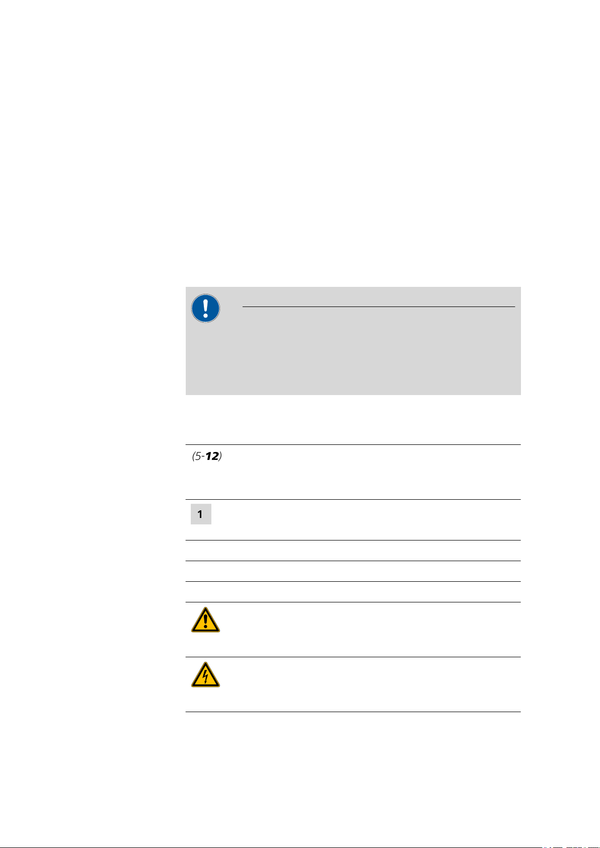
1.3.1 Symbols and conventions
The following symbols and formatting may appear in this documentation:
Method Dialog text, parameter in the software
File ▶ New Menu or menu item
[Next] Button or key
Cross-reference to figure legend
The first number refers to the figure number, the second to the instrument part in the figure.
Instruction step
Carry out these steps in the sequence shown.
WARNING
This symbol draws attention to a possible life-threatening hazard or risk of injury.
WARNING
This symbol draws attention to a possible hazard due
to electrical current.
■■■■■■■■
2
Page 11
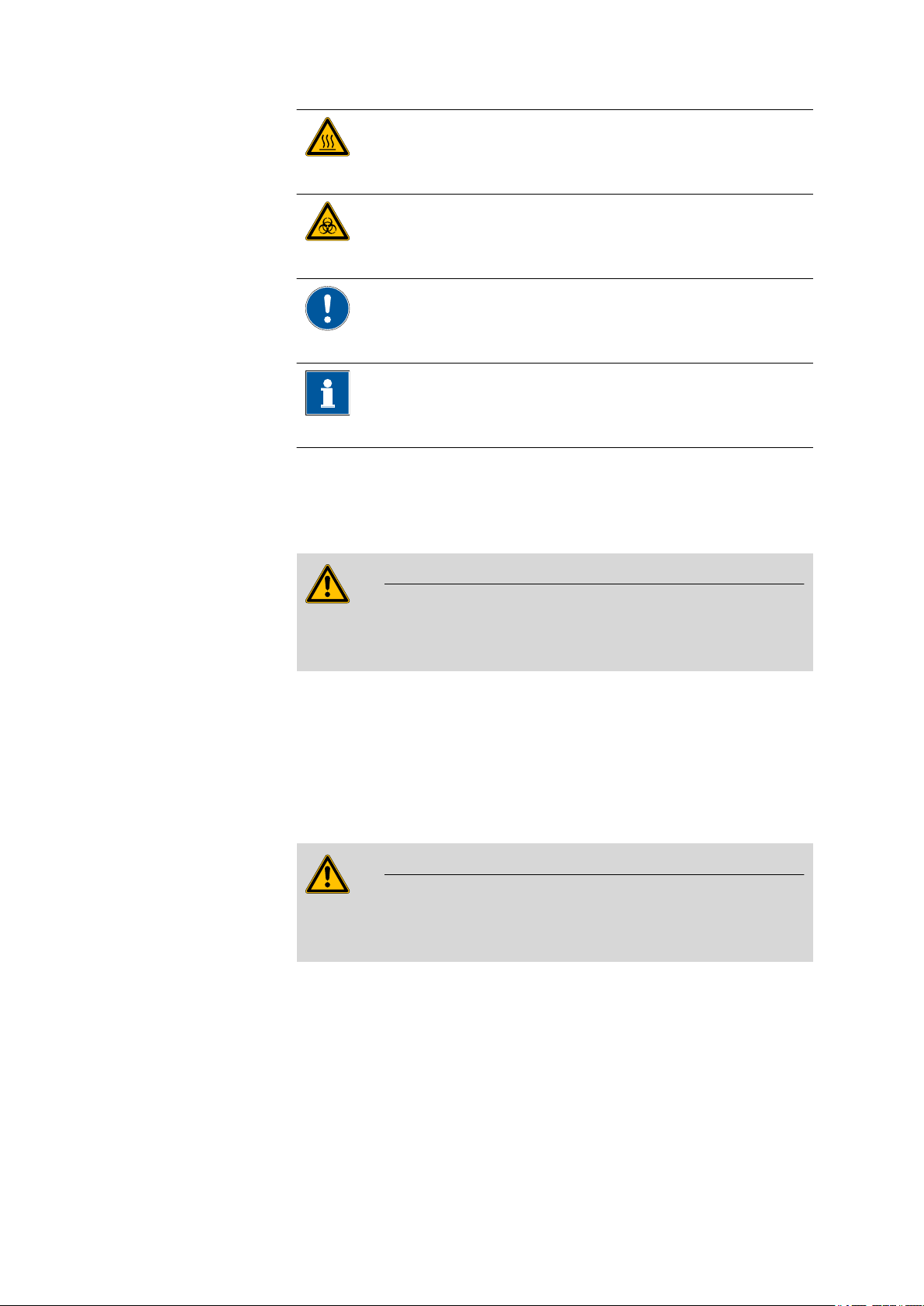
■■■■■■■■■■■■■■■■■■■■■■
1.4 Safety instructions
1 Introduction
WARNING
This symbol draws attention to a possible hazard due
to heat or hot instrument parts.
WARNING
This symbol draws attention to a possible biological
hazard.
CAUTION
This symbol draws attention to possible damage to
instruments or instrument parts.
NOTE
This symbol highlights additional information and
tips.
1.4.1 General notes on safety
WARNING
This instrument may only be operated in accordance with the specifications in this documentation.
This instrument has left the factory in a flawless state in terms of technical
safety. To maintain this state and ensure non-hazardous operation of the
instrument, the following instructions must be observed carefully.
1.4.2 Electrical safety
The electrical safety when working with the instrument is ensured as part
of the international standard IEC 61010.
WARNING
Only personnel qualified by Metrohm are authorized to carry out service
work on electronic components.
■■■■■■■■
3
Page 12
1.4 Safety instructions
■■■■■■■■■■■■■■■■■■■■■■
WARNING
Never open the housing of the instrument. The instrument could be
damaged by this. There is also a risk of serious injury if live components
are touched.
There are no parts inside the housing which can be serviced or replaced
by the user.
Supply voltage
WARNING
An incorrect mains voltage can damage the instrument.
Only operate this instrument with a mains voltage specified for it (see
rear panel of the instrument).
1.4.3 Flammable solvents and chemicals
WARNING
All relevant safety measures are to be observed when working with
flammable solvents and chemicals.
■ Set up the instrument in a well-ventilated location (e.g. fume cup-
board).
■ Keep all sources of flame far from the workplace.
■ Clean up spilled liquids and solids immediately.
■ Follow the safety instructions of the chemical manufacturer.
1.4.4 Recycling and disposal
This product is covered by European Directive 2002/96/EC, WEEE – Waste
from Electrical and Electronic Equipment.
The correct disposal of your old equipment will help to prevent negative
effects on the environment and public health.
More details about the disposal of your old equipment can be obtained
from your local authorities, from waste disposal companies or from your
local dealer.
■■■■■■■■
4
Page 13
■■■■■■■■■■■■■■■■■■■■■■
2 Overview of the instrument
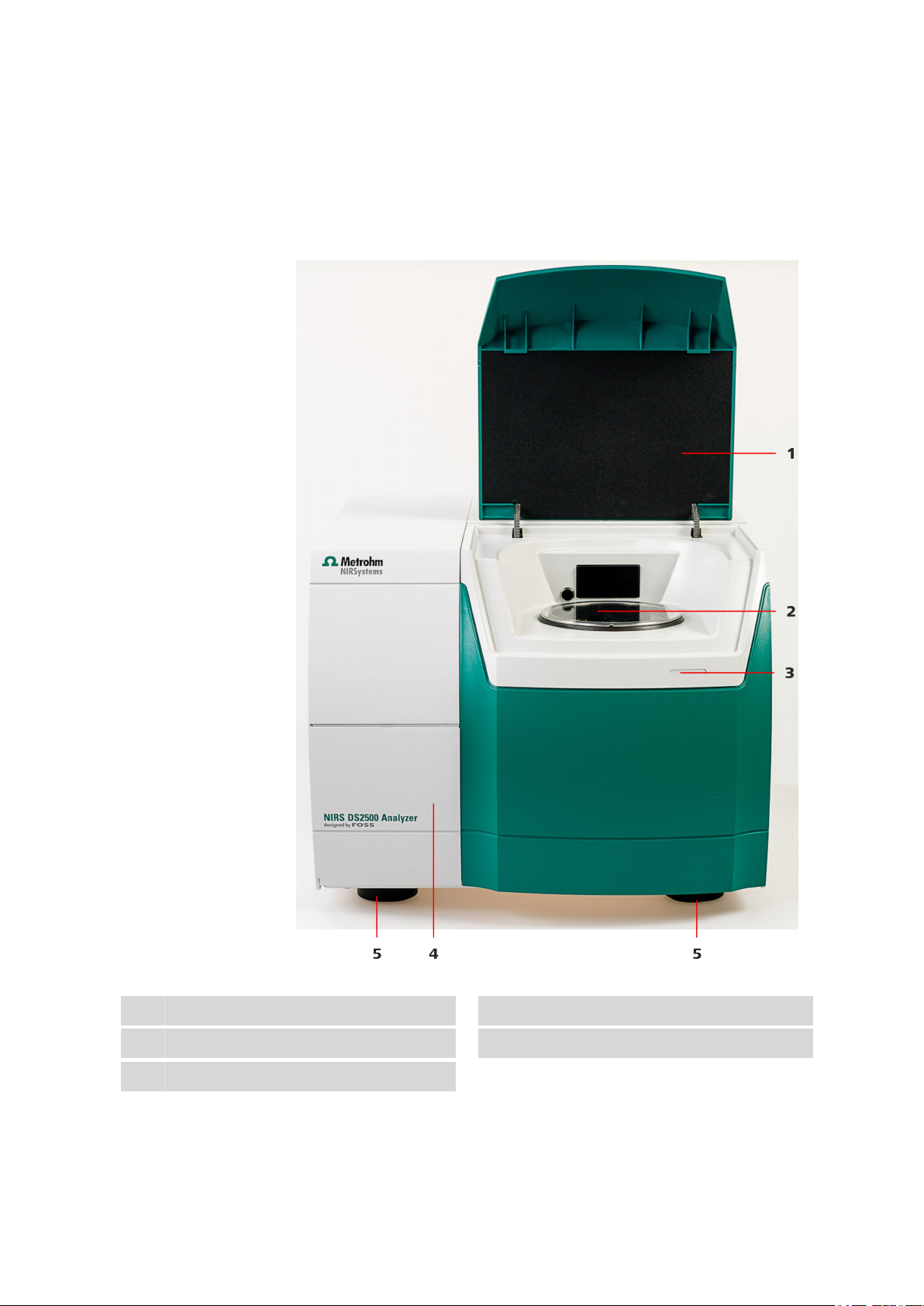
2.1 Front
2 Overview of the instrument
Cover
1
LED display
3
Feet (shock-absorbing)
5
Figure 1 Front NIRS DS2500 Analyzer
Sampling window
2
Lamp compartment
4
■■■■■■■■
5
Page 14
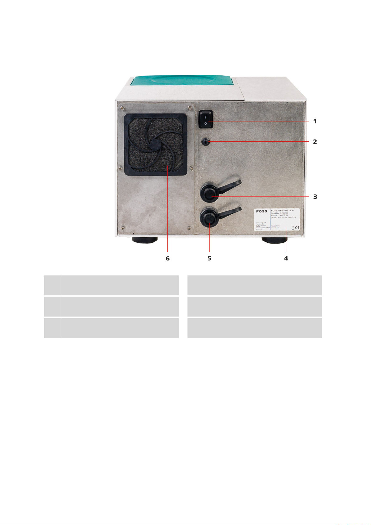
2.2 Rear
2.2 Rear
■■■■■■■■■■■■■■■■■■■■■■
Figure 2 Rear NIRS DS2500 Analyzer
On/off switch
1
For switching the instrument on and off.
Power socket
3
Sealed with protective cap.
LAN connection socket
5
Sealed with protective cap.
Fuse holder
2
Type plate
4
Fan
6
With filter.
■■■■■■■■
6
Page 15

■■■■■■■■■■■■■■■■■■■■■■
3 Installation
3.1 Unpacking and inspecting the instrument
3.1.1 Packaging
The instrument is supplied in highly protective special packaging together
with the separately packed accessories. Keep this packaging, as only this
ensures safe transportation of the instrument.
3.1.2 Checks
Immediately after receipt, check whether the shipment has arrived complete and without damage by comparing it with the delivery note.
3.1.3 Scope of application
The NIRS DS2500 Analyzer is designed for offline use in the laboratory or
atline use in the production process.
3 Installation
3.2 Setting up the instrument
Like most high-precision instruments, the NIRS DS2500 Analyzer is sensitive to ambient conditions, which may negatively influence its performance and shorten its service life. The following guidelines have to be
observed when the instrument is set up and put into operation:
3.2.1 Ambient conditions
The ambient conditions are decisive for a proper functioning and to
ensure accurate measured values. These conditions are listed in the technical specifications (see Chapter 8.3, page 33).
High humidity and unexpectedly large fluctuations in the room climate do
not hamper the instrument's performance, but they may compromise the
measuring accuracy.
■■■■■■■■
7
Page 16

3.3 Connecting the power supply cable
Problems during calibration/measurement
If the expected results are not obtained during calibration, the test runs
and measurements, then you should check the ambient conditions.
Strong draft (air conditioning, open windows, etc.) and exposure to
direct sunlight should be prevented.
Make sure to allow enough free space (on the sides and the back at
least 100 mm) around the instrument to prevent heat accumulation.
3.2.2 General conditions
Dust and dirt may compromise the instrument's cooling and should therefore be prevented as far as possible.
The maintenance procedures for the fan filter are described in Chapter
6.2.2 Replacing the fan filter, page 28.
■■■■■■■■■■■■■■■■■■■■■■
NOTE
3.2.3 Vibrations and shocks
Vibrations and shocks interfere with the sensitive optical and mechanical
components and compromise calibration and measuring accuracy.
Set up the NIRS DS2500 Analyzer at a stable workplace that does not
propagate vibrations resulting from manual work (e.g. typing on the computer keyboard). Do not set up other instruments that cause vibrations
and shocks (mills, mixers, stirrers, etc.) on the same workplace.
3.3 Connecting the power supply cable
The NIRS DS2500 Analyzer's power supply unit is supplied as part of the
NIRS DS2500 Accessory Kit (6.7400.030). The power supply unit is fitted
with a socket for a standard power supply cable (DIN EN 60320-1), which
can be used for connecting to the power supply.
Connecting the power supply cable
Required accessories
■ NIRS DS2500 power supply unit
■ Power supply cable, DIN EN 60320-1
Make sure that the instrument is switched off.
1
Remove the protective cap from the power socket (2-3).
2
■■■■■■■■
8
Page 17

■■■■■■■■■■■■■■■■■■■■■■
Plug the cable of the power supply unit into the power socket and
3
tighten it.
Plug the power supply cable into the socket of the power supply
4
unit.
Connect the other end of the power supply cable to the power sup-
5
ply.
3 Installation
■■■■■■■■
9
Page 18

3.4 Connecting the data cable
3.4 Connecting the data cable
To be controlled, the NIRS DS2500 Analyzer is connected to a computer
either directly or via a local network (LAN).
Use the supplied crossover data cable for connecting the instrument
directly to a computer's network card.
For a connection via your local network, you will need a straight-through
cable, which is not supplied with the instrument. As network configurations vary considerably across different companies, a full discussion is not
possible in this manual. We recommend that you have your network specialist establish the connection between the instrument and the company
network.
Connecting the computer directly
■■■■■■■■■■■■■■■■■■■■■■
Required accessories
■ NIRS DS2500 data cable
■ Computer with installed Vision software
Remove the protective cap from the LAN connection socket (2-5).
1
Plug the cable into the LAN connection socket and tighten it.
2
■■■■■■■■
10
Page 19

■■■■■■■■■■■■■■■■■■■■■■
Connect the other end of the data cable to the computer's network
3
cable connector.
3 Installation
3.5 Switching on the instrument
Switching on the instrument
Turn the on/off switch to the position I.
1
■ The LED display on the front of the NIRS DS2500 Analyzer (1-3)
lights up.
■ The instrument performs a self-test.
■ The sample compartment lid opens.
Wait until the software has recognized the instrument.
2
■■■■■■■■
11
Page 20

3.6 Initial start-up
3.6 Initial start-up
The initial start-up of the instrument is always carried out with the Vision
software.
This manual contains a short overview of the required steps. You can find
detailed information on the procedure in the tutorial for the software.
■■■■■■■■■■■■■■■■■■■■■■
Non-regulated industries
Required accessories
If you put the NIRS DS2500 Analyzer into operation in a non-regulated
industry, carry out the following steps:
1. Switch on the computer.
2. Launch the software and log in.
3. Switch on the instrument and wait until the software has recognized
the instrument.
4. Create a new project.
5. Create a Data Collection Method (DCM).
6. Calibrate the instrument as follows:
a. Run Wavelength Certification.
b. Run Reference Standardization.
c. Run Instrument Calibration.
7. Run Performance Test.
Running "Wavelength Certification" and "Reference Standardization"
■ NIRS reflection standard, 2 pcs. (6.7450.000)
■ NIRS DS2500 holder for sample cup (6.7430.040)
Place the sample cup holder onto the sampling window.
1
■■■■■■■■
12
Page 21

■■■■■■■■■■■■■■■■■■■■■■
3 Installation
The metal pin on the sample cup holder must go into the indentation
on the sampling window.
■ In the software, start Wavelength Certification. Follow the
2
instructions in the software.
■ When the software prompt appears, insert the wavelength stan-
dard (WSR12007) into the opening of the holder. The label of the
wavelength standard must be visible.
■ Close the lid.
■ Wait until Wavelength Certification is completed.
■ Remove the wavelength standard from the holder.
■■■■■■■■
13
Page 22

3.6 Initial start-up
■■■■■■■■■■■■■■■■■■■■■■
■ In the software, start Reference Standardization. Follow the
3
instructions in the software.
■ When the software prompt appears, insert the reflection standard
(R8012007) into the opening of the holder. The label of the
reflection standard must be visible.
Regulated industries
■ Close the lid.
■ Wait until Reference Standardization is completed.
■ Remove the reflection standard from the holder.
If you put the NIRS DS2500 Analyzer into operation in a regulated industry, then additional tests are required after the procedures described in the
chapter "Non-regulated industries" have been performed.
In regulated industries, the Vision Pharma software version and the NIRS
reflection standard, 7 pcs. (6.7450.010) are required for the instrument to
be put into operation.
Information on which additional tests are required for your specific regulated industry can be found in the applicable standards.
■■■■■■■■
14
Page 23

■■■■■■■■■■■■■■■■■■■■■■
3.7 Setting up accessories
Metrohm supplies various sample cups for your NIRS DS2500 Analyzer:
Samples Sample cups Order number
3 Installation
Solid samples, powders NIRS mini sample cups, 10 pcs., incl. 100 dis-
posable backs
Solid samples, granulated substances NIRS DS2500 large sample cup 6.7402.050
Liquid samples and suspensions NIRS liquid sample kit transflection 6.7400.010
6.7402.030
3.7.1 Inserting the sample cup for granulated substances
Use the NIRS large sample cup (6.7402.050) for measuring coarse solid
samples (granulated substances).
Inserting the sample cup for granulated substances
Required accessories
■ NIRS DS2500 large sample cup (6.7402.050)
Clean the sample cup and the sampling window with a lens cleaner
1
cloth.
Fill the granulated substance into the sample cup.
2
Make sure that the glass bottom of the sample cup is completely
covered and that the layer of sample is at least 1 cm thick.
Place the sample cup centrally onto the sampling window.
3
■■■■■■■■
15
Page 24

3.7 Setting up accessories
3.7.2 Inserting the sample cup for powders
Use the NIRS mini sample cup with disposable back (6.7402.030) for measuring fine solid samples (powder).
Inserting the sample cup for powders
Required accessories ■ NIRS DS2500 mini sample cup (6.7402.030)
■ NIRS DS2500 holder for sample cup (6.7430.040)
Clean the sample cup and the sampling window with a lens cleaner
1
cloth.
■ Fill the powder into the sample cup.
2
Make sure that the glass bottom of the sample cup is completely
covered and that the layer of sample is at least 1 cm thick.
■ Seal the sample cup with the disposable back.
■ Place the sample cup holder onto the sampling window.
3
The metal pin on the holder must go into the indentation on the
sampling window.
■ Place the sample cup into the round opening of the holder.
■■■■■■■■■■■■■■■■■■■■■■
■■■■■■■■
16
Page 25

■■■■■■■■■■■■■■■■■■■■■■
3.7.3 Inserting the sample cup for liquid samples
Inserting the sample cup for liquid samples
Required accessories ■ NIRS liquid sample kit transflection (6.7400.010)
■ NIRS DS2500 holder for sample cup (6.7430.040)
Clean the sample cup and the sampling window with a lens cleaner
1
cloth.
■ Fill liquid sample to a height of approx. 1 cm into the sample cup.
2
■ Place the gold diffuse reflector into the liquid. Avoid air pockets
while doing so.
■ Place the sample cup holder onto the sampling window.
3
The metal pin on the holder must go into the indentation on the
sampling window.
■ Place the sample cup into the round opening of the holder.
3 Installation
■■■■■■■■
17
Page 26

4 Control
■■■■■■■■■■■■■■■■■■■■■■
The NIRS DS2500 Analyzer is operated with the Vision software.
You can find more information on working with the software in the tutorial for the software.
■■■■■■■■
18
Page 27

■■■■■■■■■■■■■■■■■■■■■■
5 Operation
5 Operation
The NIRS DS2500 Analyzer requires appropriate care. Excess contamination of the instrument may result in functional disruptions and may reduce
the service life of the essentially robust mechanics and electronics.
Clean the sampling window and the accessory parts only with lens cleaner
cloths. Do not use aggressive solvents.
■■■■■■■■
19
Page 28

6.1 Maintenance by Metrohm Service
6 Maintenance
6.1 Maintenance by Metrohm Service
Maintenance of the NIRS DS2500 Analyzer is best carried out as part of
annual service, which is performed by specialist personnel from Metrohm.
A shorter maintenance interval may be necessary if you frequently work
with caustic and corrosive chemicals.
Metrohm Service offers every form of technical advice for maintenance
and service of all Metrohm instruments.
6.2 User maintenance
■■■■■■■■■■■■■■■■■■■■■■
Table 1
Maintenance tasks and intervals
Maintenance task Maintenance interval
Cleaning the instrument when necessary
Cleaning the sample compartment when necessary
Cleaning the sampling window before every measurement
Replacing the lamp after 4,000 burning hours
if Wavelength Certification or the Performance
Test deliver unsatisfactory results.
Check the fan filter and replace it, if necessary monthly
Replacing the fuse if melted
6.2.1 Replacing the lamp
The lamp must be replaced if it is burned out or when its performance is
insufficient. Signs of an insufficient lamp performance include:
■ Measurements are impaired by noise.
■ The repeatability of the wavelengths is deteriorating.
■ The performance test is no longer completed successfully.
Required accessories
■■■■■■■■
20
Removing the lamp
■ Screwdriver
Clean the instrument before replacing the lamp. This prevents dust causing damage to the lamp's reflector.
Page 29

■■■■■■■■■■■■■■■■■■■■■■
6 Maintenance
WARNING
Electric shock
There is a danger of life-threatening electric shock if an instrument connected to the power supply is opened.
■ Switch off the instrument and remove the power supply cable
before starting with the maintenance procedure.
WARNING
Hot surface
Immediately after use, the lamp is extremely hot and can cause burns.
■ Allow the lamp to cool down for approx. 10 to 15 minutes.
■ Remove the lamp with appropriate care.
NOTE
Spare part
A new spare lamp is available from your Metrohm representative under
the article number 6.7430.050.
■ We recommend keeping spare lamps in stock.
■ Use only original lamps in the instrument.
1
Disconnecting the instrument from the power supply
■ Turn the on/off switch to the position O.
■ Pull out the power supply cable.
■ Wait 10 to 15 minutes until the lamp has cooled down.
2
Opening the lamp compartment
■ Open the cover of the lamp compartment (1-4).
■ Take the hex key out of the guide rail.
■ Unscrew the four sealing plate screws using the hex key and put
them aside.
■ Take off the sealing plate and put it aside.
■■■■■■■■
21
Page 30

6.2 User maintenance
3
Removing the lamp holder
■■■■■■■■■■■■■■■■■■■■■■
■■■■■■■■
22
■ Push the white lamp holder approx. 2 mm inwards,
■ then turn it about 45° counterclockwise and
■ then carefully pull it out straight.
■ Place the lamp on the cover with the reflector facing down.
Page 31

■■■■■■■■■■■■■■■■■■■■■■
4
Disconnecting the cables
CAUTION
Functional disruption
Do not loosen the screw terminals of the black cables.
Loosen only the screw terminals of the white cables.
6 Maintenance
■ Loosen the screw terminals of the white cables using a small
screwdriver.
■ Carefully remove the cables from the terminals.
■ Bend the cables upwards so that they stand vertically.
■■■■■■■■
23
Page 32

6.2 User maintenance
5
Removing the lamp from the holder
■ Hold the lamp by the reflector.
■ Lift the lamp holder off the lamp and the cables.
■■■■■■■■■■■■■■■■■■■■■■
Required accessories
■■■■■■■■
24
TIP: Bend the cables to mark the lamp as used.
Installing a new lamp
■ Spare lamp (6.7430.050)
■ Screwdriver
Page 33

■■■■■■■■■■■■■■■■■■■■■■
6 Maintenance
CAUTION
Damage to the lamp
Fingerprints and greasy deposits may damage the lamp.
Do not touch the glass part of the lamp or the inner side of the reflector.
1
Keeping the new lamp ready
■ Take the new lamp out of the packaging.
■ Position the lamp cables upright so that they will fit through the
rectangular opening of the lamp holder.
■ Place the lamp on the lamp compartment cover plate with the
reflector facing down.
2
Inserting the lamp into the lamp holder
■■■■■■■■
25
Page 34

6.2 User maintenance
■■■■■■■■■■■■■■■■■■■■■■
■ Guide the lamp cables through the rectangular opening of the
lamp holder.
■ Place the lamp holder onto the lamp's reflector. The spring on the
lamp holder keeps the lamp in the correct position.
3
Connecting the lamp cables
■■■■■■■■
26
■ Push the two white cables all the way into the corresponding
screw terminal by hand or using tweezers.
■ Tighten the screw terminals using the small screwdriver.
Page 35

■■■■■■■■■■■■■■■■■■■■■■
4
Inserting the lamp holder
■ First, push the white lamp holder carefully all the way into the
opening,
■ then turn it approx. 45° clockwise and
■ then slowly let it go.
6 Maintenance
5
Closing the lamp compartment
■ Place the sealing plate onto the opening. Make sure that no
cables are being pinched.
■ Insert the four screws and tighten them in crosswise sequence
using the hex key.
■ Push the hex key into the guide rail on the cover.
■ Close the lid.
6
Calibrating the instrument
The instrument has to be recalibrated every time a lamp is replaced.
■ Switch on the instrument.
■ Recalibrating the instrument (see step 6 in the chapter "Non-reg-
ulated industries", page 12).
■■■■■■■■
27
Page 36

6.2 User maintenance
6.2.2 Replacing the fan filter
The fan filter has to be checked at least once a month. If the instrument is
operated in a dusty or otherwise dirty environment, then a check is
required once or even twice a week.
The fan is located on the rear of the instrument. The filter cover is
attached to the fan filter by means of four plastic latches.
■■■■■■■■■■■■■■■■■■■■■■
Required accessories ■ Fan filter (6.7430.020)
1
Switching off the instrument
■ Turn the on/off switch (2-1) to the position O.
2
Removing the filter cover
Grab the filter cover with both hands and gently take it off starting
on top and then proceeding to the sides.
3
Checking the state of the filter
Take out the filter and inspect it carefully.
■ If the filter shows no cracks, then it can be cleaned and used
again.
■ If the filter is damaged, then a new filter has to be used.
■■■■■■■■
28
Page 37

■■■■■■■■■■■■■■■■■■■■■■
6 Maintenance
4
Cleaning the filter
■ Blow out the dirty filter with a compressed air duster spray.
■ Alternative: Rinse the dirty filter with clean water and allow to dry.
5
Mounting the filter
Place the new or cleaned filter symmetrically into the filter cover.
The filter must not be wrinkled or folded. The edges must form a
good seal.
6
Mounting the filter cover
Mount the filter cover to the frame starting on the bottom and push
it in place until all latches snap in.
7
Switching on the instrument
Turn the on/off switch (2-1) to the position I.
■■■■■■■■
29
Page 38

6.2 User maintenance
■■■■■■■■■■■■■■■■■■■■■■
6.2.3 Replacing the fuses
The fuse is located on the rear of the instrument, directly underneath the
on/off switch.
Required accessories ■ Spare fuse, type: 250 V, 5 A, slow-acting fuse, 20 mm
1
Switching off the instrument
■ Turn the on/off switch (2-1) to the position O.
NOTE
We recommend pulling out the power supply cable in addition.
The instrument can thus not be accidentally switched on while you
insert the fuse.
2
Removing the old fuse
■ Unscrew the fuse holder by hand (if necessary, unscrew it using a
size 5 flat-head screwdriver).
■ Pull the old fuse out of the holder.
■■■■■■■■
30
Page 39

■■■■■■■■■■■■■■■■■■■■■■
3
Inserting the new fuse
■ Insert a new fuse of the same type into the holder.
■ Place the fuse holder back into the opening on the rear of the
instrument and tighten by hand.
4
Switching on the instrument
■ Plug the power supply cable back in.
■ Turn the on/off switch (2-1) to the position I.
6 Maintenance
■■■■■■■■
31
Page 40

7.1 Malfunction during start-up
7 Troubleshooting
7.1 Malfunction during start-up
Problem Cause Remedy
■■■■■■■■■■■■■■■■■■■■■■
The instrument does
not start.
The power supply cable is
not or incorrectly connected.
The fuse has melted. Replace the fuse (see Chapter 6.2.3, page 30).
Correctly connect the power supply cable (see
"Connecting the power supply cable", page
8).
7.2 Error messages from the software
Problem
Error 4209 "Lamp is
not on"
Error 4210 "Sample
holder in wrong
position"
Error 4211 "Sample
holder moved during scan"
Cause Remedy
The lamp is no longer burning.
The sample cup is inserted
incorrectly.
The sample compartment
window lid is open.
The sample cup is inserted
incorrectly.
Replace the lamp (see Chapter 6.2.1, page
20).
Insert the sample cup correctly (see Chapter
3.7, page 15).
Close the lid of the sample compartment.
Insert the sample cup correctly (see Chapter
3.7, page 15).
Error 4234 "Sample
cup jammed"
Error 4236 "Door
open"
■■■■■■■■
32
The sample cup is jammed. Insert the sample cup correctly (see Chapter
3.7, page 15).
The sample compartment
window lid is open.
Close the lid of the sample compartment.
Page 41

■■■■■■■■■■■■■■■■■■■■■■
8 Technical specifications
8.1 Interfaces
8 Technical specifications
Ethernet connection socket
Ethernet connector for data transmission to a PC
8.2 Power connection
Nominal voltage
range
Frequency 50 and 60 Hz (autosensing)
Fuse Diameter 5 mm, length 20 mm
100 to 240 V ± 10% (autosensing)
250 V, 5 A (slow-acting)
8.3 Ambient conditions
Temperature
range
Operation 5 to 40 °C
Storage –20 to 70 °C
Humidity < 93% relative humidity, no condensation
8.4 Operation
Measuring mode
Wavelength range 400 to 2,500 nm
Detectors Silicon (400 to 1,100 nm),
Optical bandwidth 8.75 nm (±0.10 nm)
Spectral resolution 0.5 nm
Number of data
points
Absorption range 0 to 2 AU
Analysis time < 1 minute, adjustable
Wavelength accuracy
Reflection or transflection (liquid samples)
Lead sulfide (1,100 to 2,500 nm)
4,200
< 0.05 nm (SRM 1920)
■■■■■■■■
33
Page 42

8.5 Safety specifications
Wavelength precision
Based on one
< 0.005 nm
instrument
Based on an
< 0.02 nm
instrument
group
Photometric noise
400 to 700 nm < 50 mAU
700 to 2,500
< 20 mAU
nm
8.5 Safety specifications
This instrument fulfills the following electrical safety requirements:
CE marking in accordance with the EU directives:
■ 2006/95/EC (Low Voltage Directive, LVD)
■ 2004/108/EC (EMC Directive, EMC)
■■■■■■■■■■■■■■■■■■■■■■
Design and testing According to EN/IEC/UL 61010-1, CSA-C22.2 No. 61010-1, protection
class I, EN/IEC 61010-2-010, EN/IEC 60529, degree of protection IP65.
Safety instructions This document contains safety instructions which have to be followed
by the user in order to ensure safe operation of the instrument.
8.6 Standards and directives
The instrument complies with the following directives:
■ Directive 94/62/EC (packaging and packaging waste)
■ Directive 2002/95/EC (RoHS 1)
■ Directive 2002/96/EC (waste electrical and electronic equipment)
■ Regulation 1907/2006/EC (REACH)
■■■■■■■■
34
Page 43

■■■■■■■■■■■■■■■■■■■■■■
8.7 Dimensions
Dimensions
Length 490 mm
Width 375 mm
Height 300 mm (closed)
534 mm (opened)
Weight 27 kg
8 Technical specifications
Additional free
space
at least 100 mm (on the sides and rear)
■■■■■■■■
35
Page 44

9 Warranty (guarantee)
Metrohm guarantees that the deliveries and services it provides are free of
defects in materials, design or manufacturing.
The general warranty period is 36 months (exclusions below) from the
date of delivery, or 18 months in the event of continuous operation. The
warranty remains valid on the condition that the servicing is provided by a
service organization authorized by Metrohm at defined intervals and with
a defined scope.
The warranty period for anion suppressors of the type "MSM" is 120
months from the date of delivery or 60 months in the case of continuous
operation.
The warranty period for IC separation columns is 90 days after start-up.
For third-party components that are recognizable as such, the manufacturer's warranty regulations apply.
■■■■■■■■■■■■■■■■■■■■■■
For instruments sold under the Metrohm NIRSystems brand, a full 16month warranty is applicable. In the event of continuous operation, the
warranty period is reduced by half.
Consumables and materials with limited storage life and glass breakage in
the case of electrodes or other glass parts are excluded from the warranty.
Warranty claims cannot be asserted if the ordering party has failed to
meet its payment obligations according to schedule.
During the warranty period, Metrohm undertakes either to replace free of
charge or to credit the purchaser for any modules or components that can
be shown to be faulty. Any transport or customs fees that may apply are
the responsibility of the ordering party.
The precondition for this is that the ordering party has to specify the article number, the article designation, an adequate error description, the
delivery date and (if applicable) the serial number or chip data in the Support Tracker. Metrohm then decides whether a replacement or a credit
note is to be issued or whether the faulty part has to be returned using
the Return Material Authorization (RMA). If a replacement or credit note is
issued, the ordering party undertakes to store the faulty part for at least
24 months in accordance with the current storage directives (in compliance with ESD guidelines) and to hold it in readiness for onsite inspection
or for return shipment to Metrohm. Metrohm reserves the right to invoice
the ordering party for these articles, including retroactively, in the event of
noncompliance with these preconditions.
■■■■■■■■
36
Page 45

■■■■■■■■■■■■■■■■■■■■■■
9 Warranty (guarantee)
The same warranty periods that are specified for a corresponding new
part apply to parts that are replaced or repaired within the above-mentioned warranty periods. However, replacement or repair of a part does
not extend the warranty period of the entire system.
Deficiencies arising from circumstances that are not the responsibility of
Metrohm, such as improper storage or improper use, etc., are expressly
excluded from the warranty.
Metrohm also offers a 120-month spare parts availability guarantee and a
60-month PC software support warranty, calculated from the date on
which the product is withdrawn from the market. The content of this warranty is the ability of the customer to obtain functioning spare parts or
appropriate software support at market prices during the time of the warranty period. This does not apply for software products sold under the
Metrohm NIRSystems brand.
If Metrohm AG is unable to meet this obligation due to circumstances
beyond the control of Metrohm AG, then the ordering party shall be
offered alternative solutions at preferential conditions.
■■■■■■■■
37
Page 46

10 Accessories
Up-to-date information on the scope of delivery and optional accessories
for your instrument can be found on the Internet.
When you receive your new instrument, we recommend downloading
the accessories list from the Internet, printing it out and keeping it
together with the manual for reference purposes.
Instruments currently sold
If you do not know the article number of your instrument, proceed as follows:
Downloading the accessories list
■■■■■■■■■■■■■■■■■■■■■■
NOTE
Go to the Metrohm website http://www.metrohm.com/com.
1
2
Click on .
The Search webpage will be displayed.
Enter a search term relating to the instrument into the search field
3
and click on Find.
The search results will be displayed.
In the search results, select the Devices tab (if it is not already
4
selected) and then click on the Metrohm article number of the
required instrument (e.g. 2.852.0050).
The page with information pertaining to the searched article is displayed.
Select the Parts tab.
5
The complete list of accessories with the scope of delivery and the
optional accessories will be displayed.
6
Click on .
■■■■■■■■
38
Page 47

■■■■■■■■■■■■■■■■■■■■■■
10 Accessories
The Partslists webpage will be displayed.
Select the desired output language.
7
With the article number entered, click on the command Generate
8
PDF.
The PDF file with the accessories data will be created in the language
selected.
Direct access for all instruments
If you are unable to find your instrument using the search as described
above, this may be due to the instrument not being sold anymore. Using
the article number, you can download accessories lists for all instruments
as follows:
Downloading the accessories list
Type http://partslists.metrohm.com into your Internet browser.
1
The Partslists webpage will be displayed.
Select the desired output language.
2
Enter the article number and click on the Generate PDF command.
3
The PDF file with the accessories data will be created in the language
selected.
■■■■■■■■
39
Page 48

Index
Index
■■■■■■■■■■■■■■■■■■■■■■
A
Accessories
Set up ................................ 15
D
Data connection
Establish ............................. 10
G
Guarantee ................................ 36
I
Instrument
Switch on ........................... 11
M
Mains voltage ............................. 4
Metrohm Service ...................... 20
P
Power supply
Establish ............................... 8
S
Safety instructions ...................... 3
Service ....................................... 3
Specifications ........................... 33
Start-up .................................... 12
W
Warranty .................................. 36
■■■■■■■■
40
 Loading...