

Page 1
NIRS
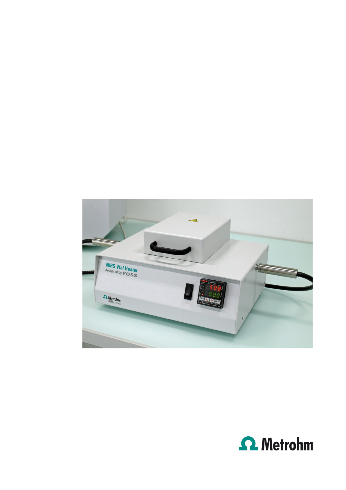
Vial Heater
Manual
8.921.8009EN
Page 2

Page 3

Metrohm AG
CH-9100 Herisau
Switzerland
Phone +41 71 353 85 85
Fax +41 71 353 89 01
info@metrohm.com
www.metrohm.com
NIRS
Vial Heater
Manual
8.921.8009EN 10.2013 fpe
Page 4

Teachware
Metrohm AG
CH-9100 Herisau
teachware@metrohm.com
This documentation is protected by copyright. All rights reserved.
Although all the information given in this documentation has been checked with great care, errors
cannot be entirely excluded. Should you notice any mistakes please send us your comments using the
address given above.
Page 5

▪▪▪▪▪▪▪
Table of contents
1 Introduction ................................................................................................................... 4
2 General Specifications and Site Readiness ...................................................................... 5
3 Installation of the Vial Heater Module ............................................................................ 7
4 Controller Operation .................................................................................................... 10
5 Maintenance and Fuse Replacement ............................................................................ 11
5.1 Fuse type .................................................................................................... 11
5.2 Fuse replacement ........................................................................................ 11
5.3 Fan filter maintenance ................................................................................ 12
6 Safety Compliance Information .................................................................................... 13
7 Index ............................................................................................................................ 14
3
Page 6

▪▪▪▪▪▪▪
1 Introduction
The Vial Heater Module is designed to operate with the Metrohm NIRS XDS monochromator,
equipped with the Optiprobe Module configured for transmission operation. The Vial Heater provides
a consistent sample temperature for optimum repeatability of sample spectra.
The Metrohm NIRSystems Vial Heater Module provides a means to pre-heat samples and controls
their temperature during the data collection process. Controlled temperature can be selected and
maintained above room temperature, and below 200 °C.
The Vial Heater Module consists of a temperature control unit and a vial heater block. The display
reads out in degrees Centigrade (°C). The upper readout is the actual heater block temperature. The
lower readout is the set point. The sample temperature set point is adjusted using the front panel
buttons, as explained in section 4.0, Controller Operation.
There is minimal maintenance required, beyond keeping the fan filter clean, and preventing spills of
liquid samples on the Vial Heater Module. Please see important safety notes in section 6 of this
manual. The Vial Heater Module operates at high temperatures. Spills, drips, and burns should be
avoided. Operators should follow all safety precautions for high temperature operation and sample
handling. Follow all precautions on the Material Safety Data Sheet (MSDS) for sample materials being
analyzed.
Maintenance is explained in section 5.0, Maintenance and Fuse Replacement. Please retain this
manual for future reference.
Note: The Vial Heater Module is designed for use with 3/8-inch fiber optic probes, operated in the
transmission mode.
4
Page 7

▪▪▪▪▪▪▪
2 General Specifications and Site Readiness
The Vial Heater Module should be placed in a
work area with adequate room for normal use,
including loading and unloading of vials, and
sufficient room for fan cooling behind the
module.
The fiber optic probes are attached on the left
and right sides of the module as shown in the
photo. Leave room for an adequate bend radius
of the fiber bundles. Fiber bundles should not be
kinked, and should not be bent in a radius of less
than 15 cm (6”).
The Metrohm NIRSystems instrument should also have adequate room for fan circulation. The system
should be mounted on a bench or work location free from vibration, direct sunlight, drafts, and
sudden changes in temperature or humidity.
The Vial Heater Module is supplied with AC power cords for both North American and international
use. The cord for international use is a “Harmonized International Power Cord” with color-coded,
stripped leads for use with approved local wiring connectors. A User Manual and a Spare Fuse
(T5A-250) are supplied.
If vials are loaded in the immediate vicinity of the equipment, care should be taken to avoid spills or
drippage onto the Vial Heater Module. A lab sink or other facilities should be provided.
Specifications are as follows:
Parameter Metric Untits Non-Metric Untis
Width (less probes) 317 mm 12.5 inches
Height, Cover closed 172 mm 6.75 inches
Height, Cover open 324 mm 12.75 inches
Depth, front to back 248 mm 9.75 inches
Weight 4.36 kg 9.55 pounds
Ambient Operating
Temperature
15…32 °C 60…90 °F
Operating Voltage 100…120 VAC or 220…240 VAC, 50…60 Hz
Maximum Power Consumption 200 Watts Maximum
Verify that all parts are received in good condition. If any parts are missing or damaged, please
contact your Metrohm NIRSystems distributor for further instructions.
5
Page 8

▪▪▪▪▪▪▪
Notice to Users:
The Vial Heater Module is designed to operate at high temperatures. Follow normal safety
procedures as required for high temperature operations. Metrohm NIRSystems is not responsible for
any misuse of the Vial Heater System, incorrect wiring methods from those stated in this manual, or
changes in the system without written authorization and approval by Metrohm NIRSystems.
6
Page 9

▪▪▪▪▪▪▪
3 Installation of the Vial Heater Module
1. Place the Vial Heater Module near the
2. Insert transmission probes into holes on
3. Secure in place with setscrews located in
instrument so that the transmission
probes will reach the heater block.
The photo shows a typical finished
installation.
Do not plug the Vial Heater Module
in to AC power at this time.
the left and right side of the Vial Heater
Module. Press firmly until both probes
bottom in the heater block.
Do not kink or bend the fiber optic
bundles. The minimum bend radius is 15
cm, or 6 inches. Do not rest heavy
objects on the fibers, as they can be
crushed or damaged.
top of heater block. The setscrews
require a 5/64” ball driver.
(A complete set of balldrivers is included
with the monochromator accessory kit.)
See photo, showing tightening of left
side setscrew.
7
Page 10

▪▪▪▪▪▪▪
4. The rear view shows the fan housing,
5. Verify that the module is set up for the
voltage selection switch and AC power
block. The operating voltage is set at the
factory for the destination country.
The user should verify the correct voltage
setting before connecting to AC power.
This is shown below.
correct input voltage. Voltage setting is
indicated by “115 V” or “230 V” showing
on the red selector switch.
The first photo at the right shows the
correct set up for 100…120 VAC
operations. The second photo shows the
correct setting for 220…240 VAC
operations.
To change voltage selection, insert a
small coin or other suitable object into
the horizontal slot and move the selector
switch up for 115 VAC, or down for 230
VAC operation.
115 Volt 230Volt
Verify the correct setting before
proceeding to the next step.
8
Page 11

▪▪▪▪▪▪▪
6. Install the correct AC power cable into
the AC power block on the back of the
Vial Heater Module.
For locations outside North America, a
“Harmonized International Power Cord”
with color-coded, stripped leads is
supplied. Install the proper plug or
connector, following all local electrical
codes. Do not tin leads.
7. Plug the power cord into an AC outlet
that supplies the correct line voltage, as
set in step 5 above. This connection
provides correct earth grounding.
8. Turn on the AC power switch on the face
of the Vial Heater Module. The meter
display will illuminate to indicate
successful power-on.
For technical questions or more information on the Vial Heater Module, please contact your local
distributor, or contact the Metrohm Service.
9
Page 12

▪▪▪▪▪▪▪
The Controller display consists of two four-digit
4 Controller Operation
displays, one RED and one GREEN.
The current set point is the lower, green display.
The current temperature of the vial block is the
top, red display.
There are four buttons below the display:
• INDEX button -- changes display mode.
• UP arrow -- used to raise a set point.
• DOWN arrow -- used to lower a set
point.
• ENTER key -- confirms a setting change.
At power-on, all display segments will illuminate.
The display will quickly change to SELF-TEST.
Once self-test is complete, the red segments
(upper display) will display the current
temperature of the Vial Heater block. The green
segments (lower display) will display the set
point.
To change the set point:
1. Press the INDEX button. The set point will be displayed in red and SP1 will be displayed in green.
2. Select the desired temperature using the UP and DOWN arrows.
3. When the correct temperature is displayed, press ENTER to set the new value. This ENTER is
required to establish the correct set-point. If not performed, the set point will not be stored in the
controller memory, and the unit will not function properly.
4. After the value has been set, press INDEX to return to the normal operation mode. The actual
temperature will now be in RED and the desired temperature will be displayed in GREEN.
Once the displayed temperature of the Vial Heater module stabilizes, analyze the sample according to
your established analytical protocol.
WARNING!
The vial heater block may be operated at temperatures in excess of 200 °C. DO NOT touch
the block or severe burns could occur. Always handle vials with an appropriate holding
device. Follow established safety methods whenever handling hot objects.
The Vial Heater Block retains heat and may be dangerously hot even when module is
turned off or unplugged. Never touch the heater block without first measuring its
temperature.
10
Page 13

▪▪▪▪▪▪▪
5 Maintenance and Fuse Replacement
Fuse Type: T5A-250
The international symbol for electrical potential indicates that electrical power
The international symbol for caution indicates that the user should be aware of
1. Turn Vial Heater Module off using the
5.1 Fuse type
Location: AC input block on back panel
To open the fuse door, use a small flatbladed
screwdriver.
Note: A blown fuse may be an indication of an electrical fault of some sort, or may be caused by
electrical transients. Whenever replacing a blown fuse, always inspect the system for items like frayed
wires, damage, or unsafe conditions. If any of these conditions are present, they must be repaired
before use of the Vial Heater Module.
may be present if AC power is applied.
danger if instructions are not followed.
5.2 Fuse replacement
front-panel switch.
2. Remove the AC power cord from the AC
input block.
3. Open the fuse door using a small flatbladed screwdriver as shown.
4. Lift out the old fuse and discard.
5. Insert the new fuse into the fuse clip and
snap in place by closing fuse door.
6. Reinstall the AC power cord and turn the
Vial Heater Module on.
7. Order a spare fuse immediately.
T5A-250 fuse inserts in plastic clip
11
Page 14

▪▪▪▪▪▪▪
1. To open the fan filter, grasp the outer black
5.3 Fan filter maintenance
Inspect the fan filter at least once per month. It must be kept clean for the unit to operate properly. If
dirty, remove AC power and follow these steps:
cover and gently pull it away from the module.
The filter material is inside the cover.
2. Remove the filter material and blow it clean
with laboratory compressed air.
3. Reinstall the filter material in the cover and
snap it back on to the fan housing. Apply AC
power to resume normal operation.
12
Page 15

▪▪▪▪▪▪▪
6 Safety Compliance Information
WARNING
The display and control unit are designed to comply with the following:
Application of Council Directive:
• 89/336/EEC
• 73/23/EEC
• 93/68/EEC
Standards to which Conformity is declared:
• EN61010-1 (1993 with Amendment A2: July 1995)
• EN50081-1 (1992 Edition)
• EN50082-1 (1997 Edition)
Use of this product in a manner inconsistent with its labeling and these instructions is prohibited.
Notice to Users:
The Vial Heater Module is designed to operate at high temperatures. Follow normal safety
procedures as required for high temperature operations. Metrohm NIRSystems is not responsible for
any misuse of the Vial Heater System, incorrect wiring methods from those stated in this manual or
changes in the system without written authorization and approval by Metrohm NIRSystems.
Vials must be filled prior to loading into the Vial Heater Module. Do not fill the vial to the very top, or
it may spill sample onto the heating block. If sample is spilled onto the heating block, it may be
baked on, which must be avoided.
Use caution when loading and unloading vials to prevent any spills or drips. If sample is spilled onto
the Vial Heater Module, immediately turn power off, unplug the unit, and let it cool to room
temperature.
This label appears on the cover and near where vials are inserted for analysis.
The surface temperature of the plate may reach 200 degrees Celsius.
This temperature may cause burns to unprotected flesh.
Always follow lab safety procedures when loading, unloading, or handling
vials.
Once cool, the sample spill should be cleaned using appropriate solvents, and following all
recommended safety precautions.
13
Page 16

▪▪▪▪▪▪▪
7 Index
AC power cord ........................................... 11
AC power switch .......................................... 9
Controller ............................................... 4, 10
Fan filter maintenance ................................ 12
Fuse Replacement ................................... 4, 11
General Specifications ................................... 5
Harmonized International .......................... 5, 9
Height .......................................................... 5
Help Desk ................................................. 5, 9
INDEX button.............................................. 10
Label ........................................................... 13
Material Safety Data Sheet ............................ 4
Monochromator ....................................... 4, 7
MSDS ............................................................ 4
Optiprobe Module ........................................ 4
Power cords .................................................. 5
SELF-TEST ................................................... 10
Set-point ..................................................... 10
Site Readiness ............................................... 5
Spare Fuse .................................................... 5
Specifications ................................................ 5
Temperature ................................................. 5
Voltage ..................................................... 5, 8
Weight.......................................................... 5
14
 Loading...