

Page 1
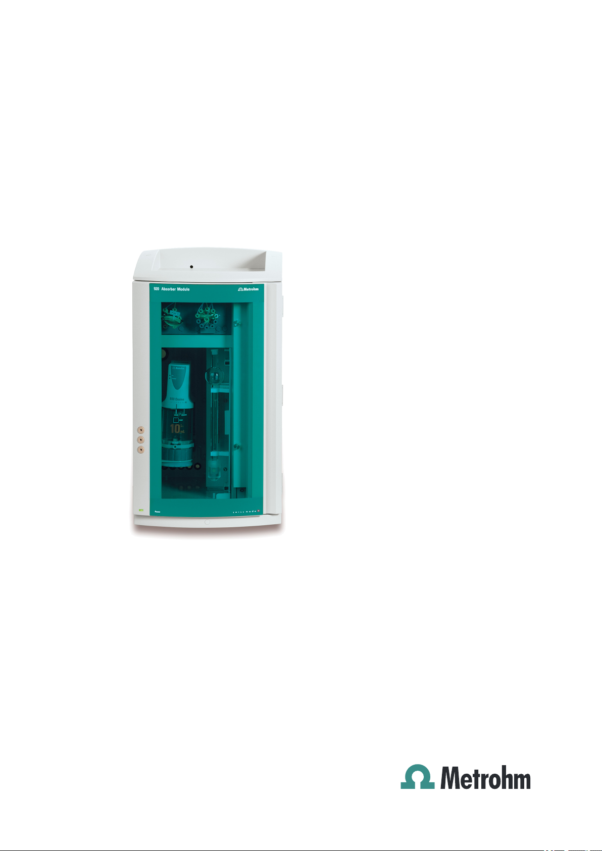
920 Absorber Module
Manual
8.920.8004EN
Page 2

Page 3

Metrohm AG
CH-9100 Herisau
Switzerland
Phone +41 71 353 85 85
Fax +41 71 353 89 01
info@metrohm.com
www.metrohm.com
920 Absorber Module
2.920.0010
8.920.8004EN
Manual
09.2013 zst
Page 4

Teachware
Metrohm AG
CH-9100 Herisau
teachware@metrohm.com
This documentation is protected by copyright. All rights reserved.
Although all the information given in this documentation has been
checked with great care, errors cannot be entirely excluded. Should you
notice any mistakes please send us your comments using the address
given above.
Documentation in additional languages can be found on
http://documents.metrohm.com.
Page 5

■■■■■■■■■■■■■■■■■■■■■■
Table of contents
1 Introduction 1
1.1 Instrument description ......................................................... 1
1.2 Intended use ......................................................................... 2
1.3 About the documentation ................................................... 2
1.3.1 Content and scope .................................................................. 2
1.3.2 Symbols and conventions ........................................................ 3
1.4 Safety instructions ................................................................ 4
1.4.1 General notes on safety ........................................................... 4
1.4.2 Electrical safety ........................................................................ 4
1.4.3 Tubing and capillary connections ............................................. 5
1.4.4 Flammable solvents and chemicals ........................................... 5
1.4.5 Recycling and disposal ............................................................. 5
2 The Combustion IC system 7
Table of contents
2.1 Overview ................................................................................ 7
2.2 System description ............................................................... 8
2.3 Sequence of a determination .............................................. 9
3 Overview of the instrument 11
3.1 Front .................................................................................... 11
3.2 Rear ...................................................................................... 15
4 Installation 17
4.1 Setting up the instrument .................................................. 17
4.1.1 Packaging .............................................................................. 17
4.1.2 Checks .................................................................................. 17
4.1.3 Location ................................................................................ 17
4.2 Overview ............................................................................. 17
4.3 Dosino for ultrapure water ................................................ 20
4.3.1 Assembling the Dosino .......................................................... 23
4.3.2 Feeding the capillary into the instrument ............................... 23
4.3.3 Connecting the ports – Overview ........................................... 24
4.3.4 Inserting the Dosino in the instrument ................................... 33
4.3.5 Connecting the Metrosep I Trap 1 ......................................... 34
4.3.6 Connecting the ultrapure water bottle ................................... 36
920 Absorber Module
4.4 Dosino for the absorber solution ...................................... 39
4.4.1 Assembling the Dosino .......................................................... 40
4.4.2 Connecting the ports – Overview ........................................... 41
4.4.3 Inserting the Dosino in the instrument ................................... 46
4.4.4 Connecting the T connection ................................................. 47
■■■■■■■■
III
Page 6

Table of contents
■■■■■■■■■■■■■■■■■■■■■■
4.4.5 Connecting the Metrosep A Trap 1 ........................................ 49
4.4.6 Connecting the bottle with the absorber solution .................. 52
4.5 10-port valve ....................................................................... 54
4.5.1 Connecting the ports ............................................................. 55
4.5.2 Connecting the bottle with the standard solution .................. 58
4.5.3 Connecting the bottle with the check standard ...................... 59
4.5.4 Function of the 10-port valve ................................................. 60
4.6 6-port valve ......................................................................... 61
4.6.1 Connecting the ports ............................................................. 62
4.6.2 Mode of operation of the 6-port valve ................................... 65
4.7 Absorber tube ..................................................................... 67
4.8 Connecting the drainage tubing and leak sensor ............ 70
4.8.1 Installing the drainage tubing ................................................ 71
4.8.2 Connecting the leak sensor .................................................... 72
4.9 Connecting the instrument ................................................ 73
4.9.1 Connecting the instrument to the PC ..................................... 73
4.9.2 Connecting the instrument to power supply .......................... 73
4.10 Connecting the 920 Absorber Module to the remaining
components ........................................................................ 74
4.10.1 Connecting the Combustion Module inlet: water infeed ........ 74
4.10.2 Connecting the Combustion Module outlet: Absorber solu-
tion ....................................................................................... 76
4.10.3 Connecting the 930 Compact IC Flex ..................................... 78
5 Start-up 79
6 Operation and maintenance 81
6.1 General ................................................................................ 81
6.2 Door ..................................................................................... 81
6.3 Dosino .................................................................................. 81
6.4 Dosing unit .......................................................................... 81
6.5 Metrosep I Trap 1 ............................................................... 82
6.6 Metrosep A Trap 1 ............................................................. 82
6.7 10-port valve ....................................................................... 82
6.8 6-port valve ......................................................................... 82
6.9 Absorber tube ..................................................................... 83
6.10 Quality Management and qualification with
Metrohm ............................................................................. 85
7 Troubleshooting 86
7.1 Problems and their solutions ............................................. 86
■■■■■■■■
IV
7.2 Problems with the Dosino ................................................. 86
920 Absorber Module
Page 7

■■■■■■■■■■■■■■■■■■■■■■
8 Technical specifications 87
Table of contents
7.3 Problems with the dosing units ........................................ 86
8.1 Reference conditions .......................................................... 87
8.2 Ambient conditions ............................................................ 87
8.3 Housing ............................................................................... 87
8.4 Dosino .................................................................................. 88
8.5 10-port valve ....................................................................... 88
8.6 6-port valve ......................................................................... 88
8.7 Absorber tube ..................................................................... 89
8.8 Leak sensor ......................................................................... 89
8.9 Power connection ............................................................... 89
8.10 Interfaces ............................................................................. 89
8.11 Safety specification ............................................................ 90
8.12 Electromagnetic compatibility (EMC) ................................ 90
9 Warranty (guarantee) 91
10 Accessories 93
10.1 Scope of delivery ................................................................ 93
10.2 Optional accessories ........................................................ 102
Index 104
920 Absorber Module
■■■■■■■■
V
Page 8

Table of figures
Table of figures
Figure 1 Detectable elements .......................................................................... 7
Figure 2 Overview - CIC system ....................................................................... 8
Figure 3 Sequence of the determination ......................................................... 9
Figure 4 920 Absorber Module – Front ......................................................... 11
Figure 5 920 Absorber Module – Front ......................................................... 13
Figure 6 920 Absorber Module – Rear ........................................................... 15
Figure 7 Capillaries and tubings in use – Overview ........................................ 18
Figure 8 Installing the Dosino for ultrapure water .......................................... 20
Figure 9 Connect the Dosino for ultrapure water .......................................... 25
Figure 10 Installing the Dosino for the absorber solution ................................. 39
Figure 11 Connect the Dosino for the absorber solution .................................. 42
Figure 12 Feed the capillary for the absorber solution into the instrument ....... 50
Figure 13 Connecting the 10-port valve .......................................................... 54
Figure 14 Connecting the 10-port valve .......................................................... 56
Figure 15 10-port valve – Ports ....................................................................... 60
Figure 16 10-port valve – Normal valve switchover and with a secured port .... 61
Figure 17 Connecting the 6-port valve ............................................................ 62
Figure 18 Connecting the 6-port valve ............................................................ 64
Figure 19 6-port valve – Ports ......................................................................... 65
Figure 20 6-port valve – Valve positions .......................................................... 66
Figure 21 Connect the absorber tube .............................................................. 67
Figure 22 Combustion tube – Inlet .................................................................. 75
Figure 23 Combustion tube – Outlet ............................................................... 76
■■■■■■■■■■■■■■■■■■■■■■
■■■■■■■■
VI
920 Absorber Module
Page 9

■■■■■■■■■■■■■■■■■■■■■■
1 Introduction
1.1 Instrument description
The 920 Absorber Module forms part of the Combustion IC system, which
includes a Combustion Module and an ion chromatograph in addition to
the 920 Absorber Module. The Combustion IC system can be used for
digesting solid and liquid combustible samples. The Combustion IC system's prime application is the determination of halogenides and sulfur.
The 920 Absorber Module is the connecting link between combustion and
IC analysis in the Combustion IC system. The 920 Absorber Module
absorbs the combustion gases in an aqueous medium and transfers it into
the ion chromatography system. The 920 Absorber Module performs the
necessary Liquid Handling and enables the application of various sample
preparation techniques, such as matrix elimination, preconcentration and
automated calibration.
1 Introduction
The 920 Absorber Module is comprised of the following modules:
Dosino for ultrapure water
A Dosino with a 5 mL dosing unit is inserted in the back in the 920
Absorber Module. This Dosino serves to dose water for the water infeed
during combustion and for the transfer of the absorption solution to the
IC instrument. Furthermore, it is used for the Liquid Handling.
Dosino for the absorber solution
A Dosino with a 10 mL dosing unit is inserted in the front of the 920
Absorber Module. This Dosino serves to dose the absorber solution into
the absorber tube.
10-port valve
The 10-port valve is the centerpiece of the Liquid Handling; it serves as a
switch-over point between the various liquid flows.
6-port valve
The 6-port valve serves as a switch-over point between the two liquid
flows. The sample loop allows a precisely defined sample amount to be
measured before it is transferred to the analyzer.
920 Absorber Module
Absorber tube
The combustion gases are absorbed by a solution in the absorber tube.
■■■■■■■■
1
Page 10

1.2 Intended use
Leak sensor
The leak sensor detects leaking liquid that collects in the instrument's base
tray. Liquid that leaks in the instrument is routed to the base tray using
drainage tubing and detected there.
1.2 Intended use
The 920 Absorber Module represents the connecting link between combustion and IC analysis in a Combustion IC system. It absorbs the combustion gases in an absorber solution and transfers the resulting sample to an
ion chromatograph. Furthermore, the 920 Absorber Module allows additional sample preparation techniques to be applied.
The present instrument is suitable for processing chemicals and flammable
samples. Usage of the 920 Absorber Module therefore requires the user
to have basic knowledge and experience in handling toxic and caustic
substances. Knowledge with respect to the application of the fire prevention measures prescribed for laboratories is also mandatory.
■■■■■■■■■■■■■■■■■■■■■■
1.3 About the documentation
CAUTION
Please read through this documentation carefully before putting the
instrument into operation. The documentation contains information
and warnings which the user must follow in order to ensure safe operation of the instrument.
1.3.1 Content and scope
This manual focuses on the 920 Absorber Module instrument, which
forms part of the Combustion IC system.
Separate manuals exist for the other modules of the Combustion IC system:
■ Manuals for the Combustion Module including Auto Boat Drive (ABD)
and optional sampler (MMS 5000) from Analytik Jena (PDFs available
on the enclosed CD)
■ Manual for 930 Compact IC Flex
■ Manual for 800 Dosino
■ Manual for 807 Dosing Unit
■■■■■■■■
2
920 Absorber Module
Page 11
■■■■■■■■■■■■■■■■■■■■■■
1.3.2 Symbols and conventions
The following symbols and formatting may appear in this documentation:
Method Dialog text, parameter in the software
File ▶ New Menu or menu item
[Next] Button or key
1 Introduction
Cross-reference to figure legend
The first number refers to the figure number, the second to the instrument part in the figure.
Instruction step
Carry out these steps in the sequence shown.
WARNING
This symbol draws attention to a possible life-threatening hazard or risk of injury.
WARNING
This symbol draws attention to a possible hazard due
to electrical current.
WARNING
This symbol draws attention to a possible hazard due
to heat or hot instrument parts.
WARNING
This symbol draws attention to a possible biological
hazard.
CAUTION
This symbol draws attention to possible damage to
instruments or instrument parts.
NOTE
This symbol highlights additional information and
tips.
920 Absorber Module
■■■■■■■■
3
Page 12
1.4 Safety instructions
1.4 Safety instructions
1.4.1 General notes on safety
WARNING
This instrument may only be operated in accordance with the specifications in this documentation.
This instrument has left the factory in a flawless state in terms of technical
safety. To maintain this state and ensure non-hazardous operation of the
instrument, the following instructions must be observed carefully.
1.4.2 Electrical safety
The electrical safety when working with the instrument is ensured as part
of the international standard IEC 61010.
WARNING
■■■■■■■■■■■■■■■■■■■■■■
Only personnel qualified by Metrohm are authorized to carry out service
work on electronic components.
WARNING
Never open the housing of the instrument. The instrument could be
damaged by this. There is also a risk of serious injury if live components
are touched.
There are no parts inside the housing which can be serviced or replaced
by the user.
Mains voltage
WARNING
An incorrect mains voltage can damage the instrument.
Only operate this instrument with a mains voltage specified for it (see
rear panel of the instrument).
■■■■■■■■
4
920 Absorber Module
Page 13
■■■■■■■■■■■■■■■■■■■■■■
Protection against electrostatic charges
WARNING
Electronic components are sensitive to electrostatic charges and can be
destroyed by discharges.
Do not fail to pull the mains cable out of the mains connection socket
before you set up or disconnect electrical plug connections at the rear
of the instrument.
1.4.3 Tubing and capillary connections
CAUTION
Leaks in tubing and capillary connections are a safety risk. Tighten all
connections well by hand. Avoid applying excessive force to tubing
connections. Damaged tubing ends lead to leakage. Appropriate tools
can be used to loosen connections.
1 Introduction
Check the connections regularly for leakage. If the instrument is used
mainly in unattended operation, then weekly inspections are mandatory.
1.4.4 Flammable solvents and chemicals
WARNING
All relevant safety measures are to be observed when working with
flammable solvents and chemicals.
■ Set up the instrument in a well-ventilated location (e.g. fume cup-
board).
■ Keep all sources of flame far from the workplace.
■ Clean up spilled liquids and solids immediately.
■ Follow the safety instructions of the chemical manufacturer.
1.4.5 Recycling and disposal
This product is covered by European Directive 2002/96/EC, WEEE – Waste
from Electrical and Electronic Equipment.
920 Absorber Module
The correct disposal of your old equipment will help to prevent negative
effects on the environment and public health.
■■■■■■■■
5
Page 14

1.4 Safety instructions
■■■■■■■■■■■■■■■■■■■■■■
More details about the disposal of your old equipment can be obtained
from your local authorities, from waste disposal companies or from your
local dealer.
■■■■■■■■
6
920 Absorber Module
Page 15
■■■■■■■■■■■■■■■■■■■■■■
2 The Combustion IC system
2.1 Overview
Combustion is a sample preparation technique that uses burning to digest
a sample. Solid, liquid and gaseous samples that are flammable can be
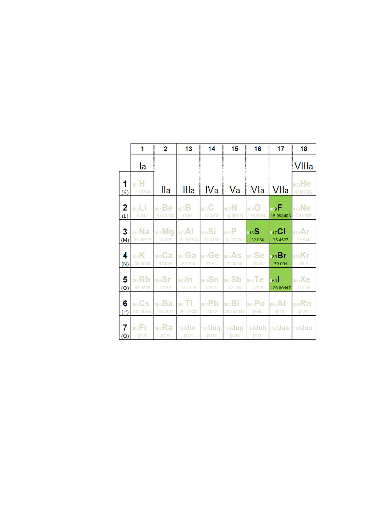
digested using combustion. Combustion IC is particularly suited for determining the following elements:
2 The Combustion IC system
920 Absorber Module
Figure 1
An additional instrument is required for the determination of gaseous
samples: the LPG/GSS Module (2.136.0720).
Detectable elements
■■■■■■■■
7
Page 16
2.2 System description
■■■■■■■■■■■■■■■■■■■■■■
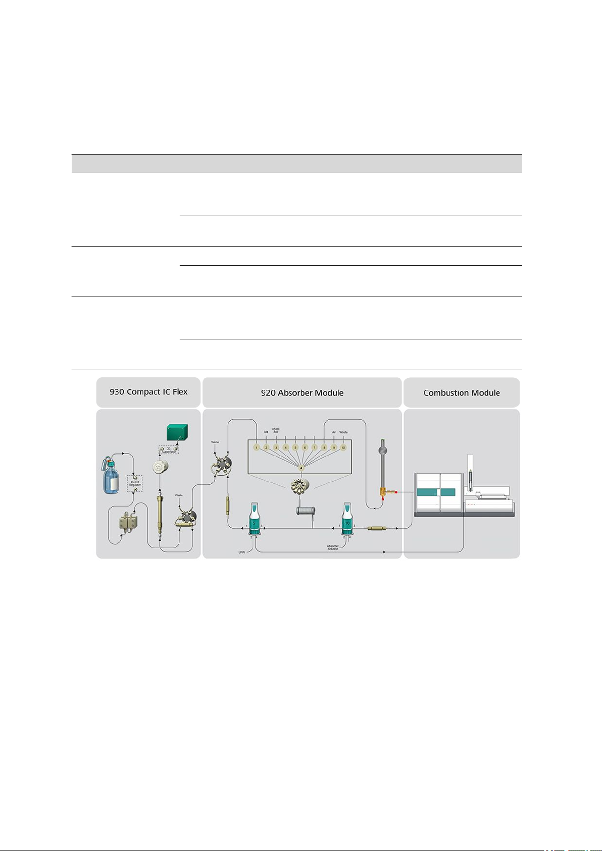
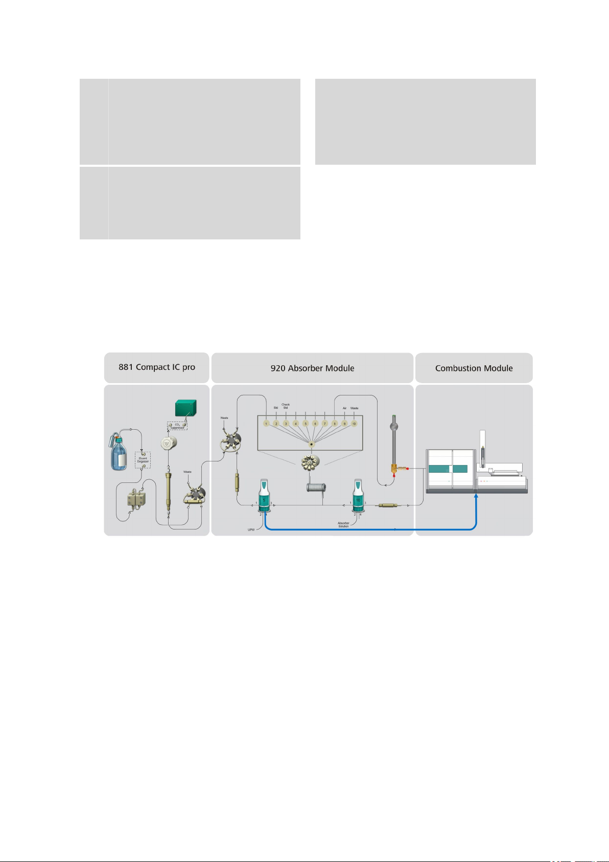
2.2 System description
Depending on the application, the Combustion IC system consists of the
following instruments:
Type of sample Instruments Manufacturer
solid/liquid samples only ■ Combustion Module with Auto Boat Drive (ABD)
(2.136.0700)
■ optional: sampler (MMS 5000)
■ 920 Absorber Module (2.920.0010)
■ 930 Compact IC Flex Oven SeS/PP/Deg (2.930.2560)
gaseous samples only ■ Combustion Module with LPG/GSS Module (2.136.0730) Analytik Jena
■ 920 Absorber Module (2.920.0010)
■ 930 Compact IC Flex Oven SeS/PP/Deg (2.930.2560)
solid, liquid and gaseous
samples
■ Combustion Module with Auto Boat Drive (ABD)
(2.136.0700)
■ LPG/GSS Module (2.136.0720)
■ 920 Absorber Module (2.920.0010)
■ 930 Compact IC Flex Oven SeS/PP/Deg (2.930.2560)
Analytik Jena
Metrohm
Metrohm
Analytik Jena
Metrohm
■■■■■■■■
8
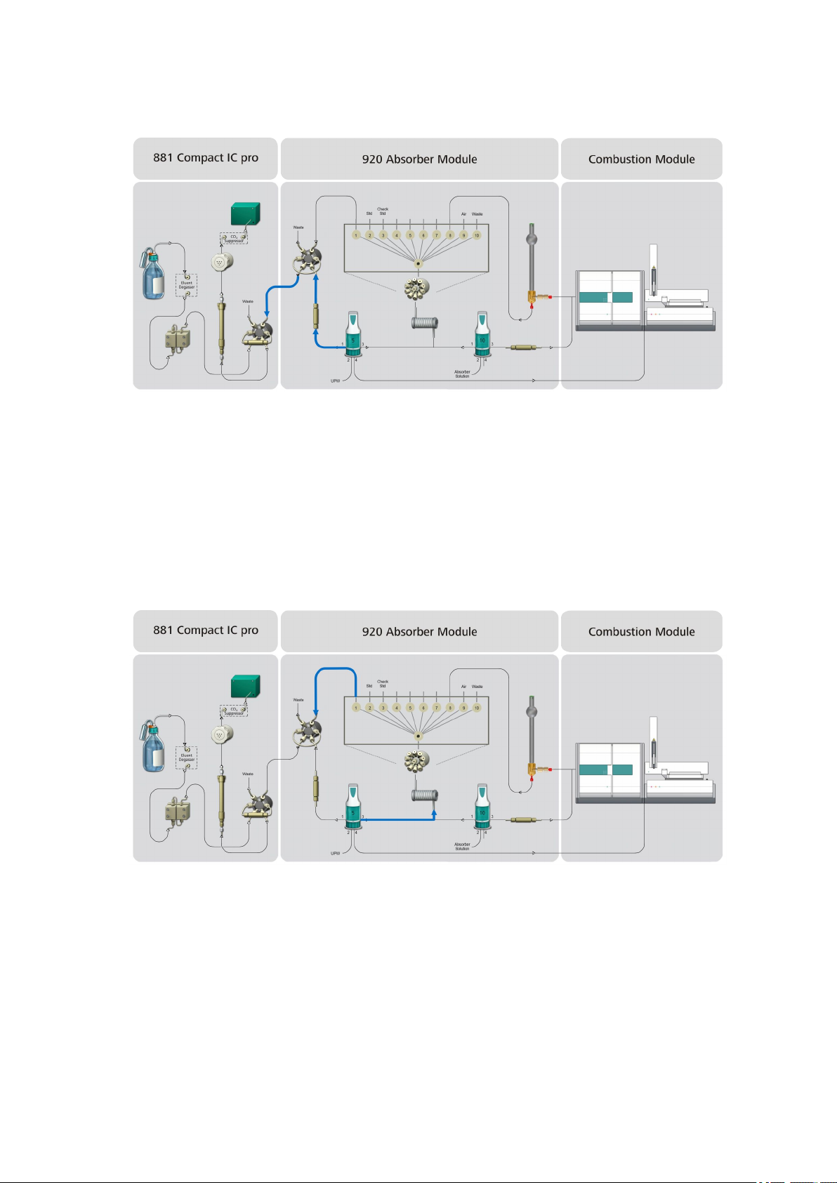
Figure 2 Overview - CIC system
The sample is combusted in the Combustion Module.
The gases generated during combustion are dissolved into an absorber
solution in the 920 Absorber Module and are optimized for analysis using
suitable sample preparation techniques.
In the end, the absorption solution is preconcentrated in an ion chromatograph and analyzed.
The entire process is controlled and monitored using MagIC Net software.
The analysis data is saved in the software's database.
920 Absorber Module
Page 17

■■■■■■■■■■■■■■■■■■■■■■
Start determination
(CIC system)
Rinse absorber tube and
provide absorber solution
(920 Absorber Module)
Sample input
(Combustion Module)
Rinse capillary f. combustion
gases w. absorber solution
(920 Absorber Module)
Absorption of
combustion gases
(920 Absorber Module)
Optional: Water infeed
(920 Absorber Module)
Combustion
(Combustion Module)
Fill loop with
absorption solution
(920 Absorber Module)
Matrix elimination
(930 Compact IC Flex)
Re-rinse absorber tube
(920 Absorber Module)
IC determination
(930 Compact IC Flex)
2.3 Sequence of a determination
A determination in the Combustion IC system runs according to the following diagram:
2 The Combustion IC system
Figure 3 Sequence of the determination
920 Absorber Module
■■■■■■■■
9
Page 18

2.3 Sequence of a determination
■■■■■■■■■■■■■■■■■■■■■■
NOTE
Do not mix these up!
■ Absorber solution: e.g. H
■ Absorption solution: Combustion gases dissolved in the absorber
solution for oxidizing sulfur oxides.
2O2
solution.
The determination is controlled entirely by MagIC Net. You can find a
detailed description of the sequence in the online help for MagIC Net
under the title "Combustion sequence".
■■■■■■■■
10
920 Absorber Module
Page 19
■■■■■■■■■■■■■■■■■■■■■■
1
2
6
11
7
9
10
3
5
4
8
3 Overview of the instrument
3.1 Front
Module overview
3 Overview of the instrument
Figure 4 920 Absorber Module – Front
Bottle holder
1
Protects the instrument from contamination
and provides the space for the liquid containers.
Transfer tubing
2
Pre-installed. Connects the 10-port valve
with the Dosino.
920 Absorber Module
■■■■■■■■
11
Page 20

3.1 Front
■■■■■■■■■■■■■■■■■■■■■■
10-port valve
3
For the software-controlled connection of
10 ports.
Holding clamps
5
To hold the absorber tube.
Base tray
7
Equipped with a leak sensor.
Dosino holder
9
Two holders for the two Dosinos. One on
the back panel and one on the side panel.
6-port valve
11
For sample preparation and sample transfer
to the analysis instrument.
Holding clamps
4
Two holding clamps that hold the trap columns.
Bottle holder
6
Provides space for a 100 mL bottle, e.g., for
the standard solution.
Standby indicator
8
Flashes while the instrument is being
started.
Lights up when the instrument is ready for
operation.
Accessory space
10
Space for the Dosinos, the trap columns and
the absorber tube.
■■■■■■■■
12
920 Absorber Module
Page 21
■■■■■■■■■■■■■■■■■■■■■■
5
2
1
1
1
1
1
1
6
1
1
1
1
3
3
44
3
3
Capillary feedthroughs and cable
feed-throughs
3 Overview of the instrument
Capillary guides
1
To arrange capillaries and tubings in the
instrument.
Figure 5 920 Absorber Module – Front
Capillary guide
2
For the combustion gas inlet capillary.
920 Absorber Module
■■■■■■■■
13
Page 22

3.1 Front
■■■■■■■■■■■■■■■■■■■■■■
Capillary feed-throughs
3
Between instrument and base tray. For feeding capillaries from the front to the sides of
the instrument.
Capillary openings
5
For guiding capillaries and tubings out of the
instrument.
Capillary feed-throughs
4
Between instrument and base tray. For feeding capillaries from the front to the rear of
the instrument.
Cable opening
6
For guiding Dosino cables out of the instrument.
■■■■■■■■
14
920 Absorber Module
Page 23
■■■■■■■■■■■■■■■■■■■■■■
11
1
8
2
3
5
6
11
13
14
10
4
9
12
7
11
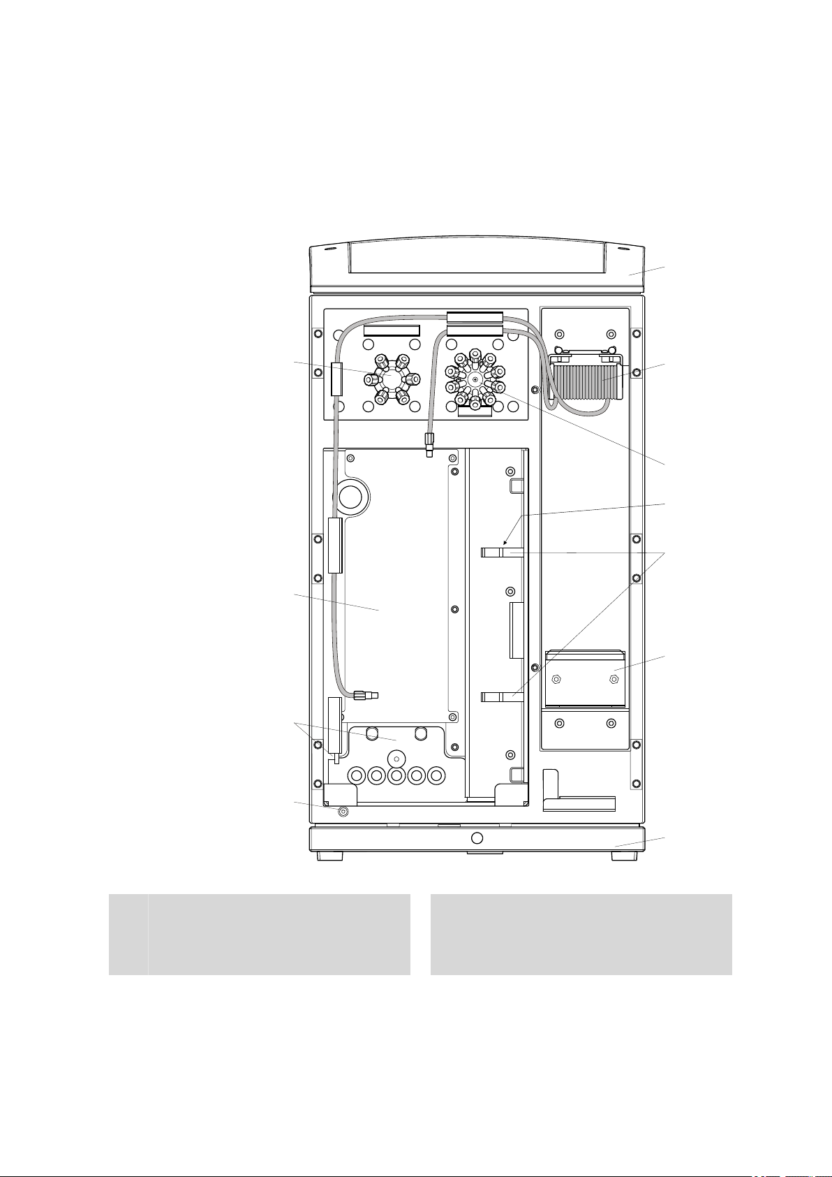
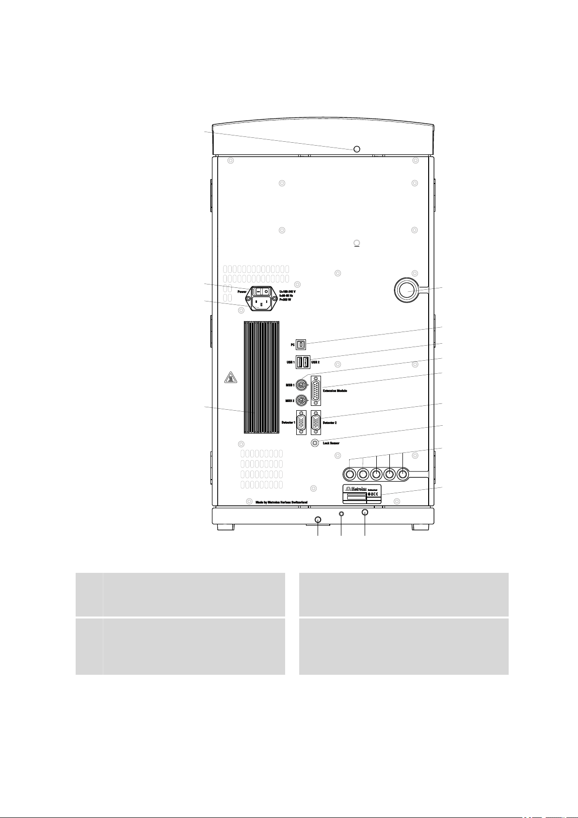
3.2 Rear
3 Overview of the instrument
Figure 6 920 Absorber Module – Rear
Cable opening
1
For guiding Dosino cables out of the instrument.
USB connection sockets
3
Two USB connection sockets for connecting
instruments with USB connector, labeled
with USB 1 and USB 2.
PC connection socket
2
For connecting a PC with a USB cable.
MSB connection sockets
4
Two MSB connection sockets for connecting
instruments with MSB connector, labeled
with MSB 1 and MSB 2.
920 Absorber Module
■■■■■■■■
15
Page 24

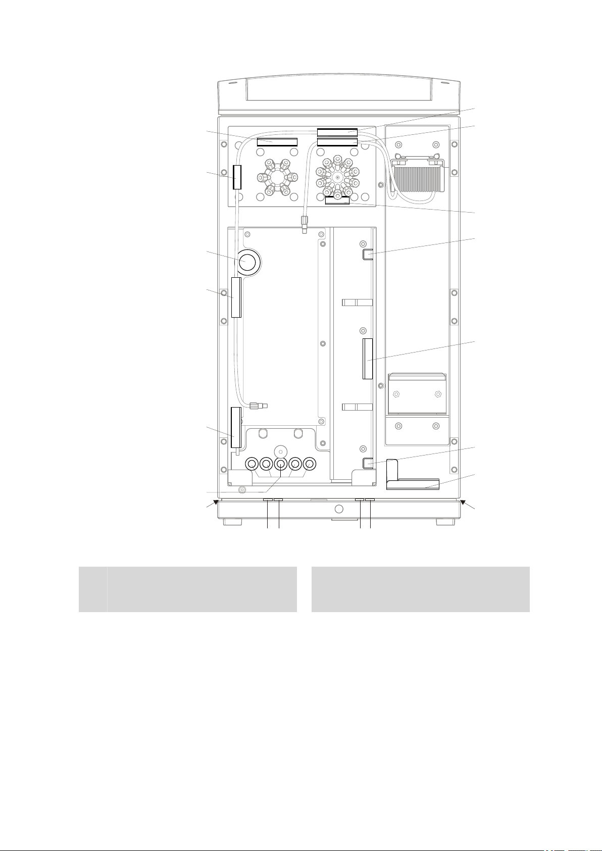
3.2 Rear
■■■■■■■■■■■■■■■■■■■■■■
Extension Module connection socket
5
Connection socket for an 872 Extension
Module or an 891 Professional Analog Out.
Leak sensor connection socket
7
For connecting the leak sensor connection
cable.
Type plate
9
With article number and barcode.
Drain nozzle
11
Enables liquids that have leaked from the
bottle holder and inside the instrument to
drain.
Power socket
13
For connecting the power supply cable.
Detector connection sockets
6
Two connection sockets for connecting up
to two detectors, labeled as Detector 1
and Detector 2.
Capillary openings
8
Five openings on the back panel for guiding
capillaries and and tubings out of the instrument.
Leak sensor cable
10
Extractable. Coiled up in the base tray. Must
be connected to the leak sensor connection
socket.
Heat sink
12
To remove heat from inside the instrument.
Caution: May become hot.
On/off switch
14
For switching the instrument on and off.
■■■■■■■■
16
920 Absorber Module
Page 25

■■■■■■■■■■■■■■■■■■■■■■
4 Installation
4.1 Setting up the instrument
4.1.1 Packaging
The instrument is supplied in highly protective special packaging together
with the separately packed accessories. Keep this packaging, as only this
ensures safe transportation of the instrument.
4.1.2 Checks
Immediately after receipt, check whether the shipment has arrived complete and without damage by comparing it with the delivery note.
4.1.3 Location
The instrument has been developed for operation indoors and may not be
used in explosive environments.
4 Installation
Place the instrument in a location of the laboratory which is suitable for
operation, free of vibrations, protected from corrosive atmosphere, and
contamination by chemicals.
The instrument should be protected against excessive temperature fluctuations and direct sunlight.
4.2 Overview
Installation of the 920 Absorber Module
The 920 Absorber Module is provided with a wide array of accessories.
These accessory parts have to be installed before the instrument can be
put into operation.
Procedure
We suggest proceeding as follows to simplify the complex installation:
1. Install the Dosino for ultrapure water including a trap column and
2. Install the Dosino for the absorber solution including a trap column,
3. Connect the 10-port valve and install the bottles for the standard
4. Connect the 6-port valve (see Chapter 4.6, page 61).
5. Install and connect the absorber tube (see Chapter 4.7, page 67).
6. Connect the Combustion Module and the 930 Compact IC Flex (see
ultrapure water bottle (see Chapter 4.3, page 20).
bottle with absorber solution and T connector (see Chapter 4.4, page
39).
solution and a check standard (see Chapter 4.5, page 54).
Chapter 4.10, page 74).
920 Absorber Module
■■■■■■■■
17
Page 26
4.2 Overview
Capillaries and tubings
■■■■■■■■■■■■■■■■■■■■■■
Figure 7 Capillaries and tubings in use – Overview
PTFE capillary, 0.75 mm ID / 3 m
1
(6.1803.160)
Connection between the 6-port valve and
the waste container.
PTFE capillary, 0.75 mm ID / 3 m
3
(6.1803.160)
Approx. 80 cm. Connection between the
10-port valve and the bottle with the standard solution.
PTFE capillary, 0.75 mm ID / 3 m
5
(6.1803.160)
Approx. 60 cm. Connection between the
10-port valve and the absorber tube.
PTFE capillary, 0.75 mm ID / 3 m
7
(6.1803.160)
Connection between the 10-port valve and
the waste container.
PEEK capillary, 0.5 mm ID / 15 cm
2
(6.1831.040)
Connection between the 6-port valve and
the 10-port valve.
PTFE capillary, 0.75 mm ID / 3 m
4
(6.1803.160)
Approx. 80 cm. Connection between the
10-port valve and the bottle with the check
standard.
PTFE capillary, 0.75 mm ID / 3 m
6
(6.1803.160)
Approx. 5 cm. For aspirating air segments.
PTFE capillary, 1/8 in. / 1/16 in. ID / 1.5
8
m
Connection between the absorber tube and
the Combustion Module.
■■■■■■■■
18
920 Absorber Module
Page 27

■■■■■■■■■■■■■■■■■■■■■■
4 Installation
PTFE capillary, 0.5 mm ID / 3 m
9
(6.1803.030)
Connection between the Metrosep A Trap 1
- 100/4.0 trap column (6.1014.000) and the
Combustion Module.
FEP tubing M6 for 920, 150 cm
11
(6.1838.020)
Aspiration tubing for the absorber solution.
Connection between the Dosino with the
absorber solution and the bottle with the
absorber solution.
FEP tubing M6 for 920, 9 cm
13
(6.1838.040)
Connection between the Dosino with ultrapure water and the T connector.
FEP tubing M6 for 920, 150 cm
15
(6.1838.020)
Aspiration tubing for ultrapure water. Connection between the Dosino with the water
bottle.
PTFE capillary, 0.5 mm ID / 3 m
10
(6.1803.030)
Approx. 20 cm. Connection between the
Dosino with the absorber solution and the
Metrosep A Trap 1 - 100/4.0 trap column
(6.1014.000).
FEP tubing M6 for 920, 9 cm
12
(6.1838.040)
Connection between the Dosino with the
absorber solution and the T connector.
PTFE capillary, 0.5 mm ID / 3 m
14
(6.1803.030)
Connection between the Dosino with ultrapure water and the Combustion Module.
PTFE capillary, 0.5 mm ID / 3 m
16
(6.1803.030)
Approx. 30 cm. Connection between the
Dosino with ultrapure water and the Metrosep I Trap 1 - 100/4.0 trap column
(6.1014.200).
PTFE capillary, 0.5 mm ID / 3 m
17
(6.1803.030)
Approx. 40 cm. Connection between the
Metrosep I Trap 1 - 100/4.0 trap column
(6.1014.200) and the 6-port valve.
PTFE capillary, 0.5 mm ID / 3 m
18
(6.1803.030)
Connection between the 6-port valve and
the 930 Compact IC Flex.
Colored sleeves Different liquids move throughout the 920 Absorber Module. In order to
provide you an overview of the different flow paths, we recommend using
the provided colored sleeves as follows to code the capillaries that route
the distinct liquids:
Table 1 Recommended color codes for the flow paths
Liquid Colored sleeve
Ultrapure water blue
Absorber solution yellow
Standard solution black
Check standard red
Waste white
920 Absorber Module
■■■■■■■■
19
Page 28
4.3 Dosino for ultrapure water
NOTE
The colored sleeves are heat-shrink tubing; this means they shrink when
they are exposed to heat.
Slip the colored sleeve over the capillary and secure it to the desired
spot by heating it, for example by using a hairdryer.
4.3 Dosino for ultrapure water
The Dosino for ultrapure water is installed first.
■■■■■■■■■■■■■■■■■■■■■■
■■■■■■■■
20
Figure 8
FEP tubing M6 for 920, 9 cm
13
(6.1838.040)
Connection between the Dosino with ultrapure water and the T connection.
Installing the Dosino for ultrapure water
PTFE capillary, 0.5 mm ID / 3 m
14
(6.1803.030)
Connection between the Dosino with ultrapure water and the Combustion Module.
920 Absorber Module
Page 29
■■■■■■■■■■■■■■■■■■■■■■
4 Installation
FEP tubing M6 for 920, 150 cm
15
(6.1838.020)
Aspiration tubing for ultrapure water. Connection between the Dosino with the water
bottle.
PTFE capillary, 0.5 mm ID / 3 m
17
(6.1803.030)
Approx. 40 cm. Connection between the
Metrosep I Trap 1 - 100/4.0 trap column
(6.1014.200) and the 6-port valve.
The Dosino is equipped with a 5 mL dosing unit and is inserted in the back
in the accessory space (4-10). It has three tasks:
■ Dosing the water infeed during combustion.
■ Dosing the transfer water for matrix elimination of the sample.
■ Liquid Handling.
Dosing the water infeed during combustion
PTFE capillary, 0.5 mm ID / 3 m
16
(6.1803.030)
Approx. 30 cm. Connection between the
Dosino with ultrapure water and the Metrosep I Trap 1 - 100/4.0 trap column
(6.1014.200).
920 Absorber Module
Feeding water in at the combustion tube's inlet supports the combustion
process and increases the recovery rate, particularly for fluoride. To do so,
the Dosino aspirates the ultrapure water from the bottle and doses a very
small amount through port 4 to the combustion tube's inlet. The time and
quantity of the water infeed are defined in MagIC Net™.
■■■■■■■■
21
Page 30
4.3 Dosino for ultrapure water
■■■■■■■■■■■■■■■■■■■■■■
Dosing transfer water for the sample
The transfer water transports the sample to the IC instrument. In order to
obtain accurate analysis results, the transfer water has to be free of ionic
contamination. To remove all traces of ionic contamination, a Metrosep I
Trap 1 – 100/4.0 (6.1014.200) column is used between the Dosino for
ultrapure water and the 6-port valve.
The Dosino aspirates ultrapure water from the bottle and starts by dosing
it to the Metrosep I Trap 1 – 100/4.0 (6.1014.200) through port 1 and to
port 5 of the 6-port valve from there.
Liquid Handling
A Dosino can either aspirate or discharge defined quantities of liquids via
its four ports. In conjunction with the 10-port valve, it is used to transport
liquids through the Combustion IC system. This process is called Liquid
Handling.
■■■■■■■■
22
Port 3 of the Dosino is connected to transfer tubing and is used for Liquid
Handling.
920 Absorber Module
Page 31

■■■■■■■■■■■■■■■■■■■■■■
4 Installation
Recommended procedure for installation
1. Assemble the Dosino (see Chapter 4.3.1, page 23).
2. Guide the capillary for the infeed of water during combustion into
the instrument (see Chapter 4.3.2, page 23).
3. Connect port 2 and port 4 (see "Connecting port 2 and port 4",
page 26).
4. Connect port 1 and port 3 (see "Connecting port 1 and port 3",
page 30).
5. Place the Dosino in the instrument (see Chapter 4.3.4, page 33).
6. Connect the Metrosep I Trap 1 - 100/4.0 trap column and insert it in
the instrument (see Chapter 4.3.5, page 34).
7. Connect the ultrapure water bottle (see Chapter 4.3.6, page 36).
4.3.1 Assembling the Dosino
Accessories
For this step you need:
■ 800 Dosino (2.800.0010)
■ Dosing Unit 5 mL (6.3032.150)
Attaching the Dosino on the Dosing Unit
The manual for the 800 Dosino describes how to attach a dosing unit correctly on the 800 Dosino.
CAUTION
Please read through the correct procedure in the manual for the 800
Dosino before you attach the Dosino on the dosing unit.
Plugging in the connection cable
Route the connection cable for the Dosino out the back panel of the
1
instrument through the cable opening (6-1).
Plug the plug from the connection cable into the MSB 2 socket.
2
Next step Feed the capillary for the water infeed (8-14) into the instrument.
4.3.2 Feeding the capillary into the instrument
Accessories
For this step you need:
■ PTFE capillary (6.1803.030)
■ Colored sleeves, blue
920 Absorber Module
■■■■■■■■
23
Page 32

4.3 Dosino for ultrapure water
6.1803.030
1.
2.
3.
■■■■■■■■■■■■■■■■■■■■■■
Feeding the capillary for the water infeed into the instrument
The arrows in the figure point in the direction the capillaries have to be
pushed.
1
Feeding the capillary for the water infeed into the instrument
■ Slide a blue colored sleeve over the capillary far enough that it
remains visible outside the instrument.
■ Push the capillary into the capillary feed-through at the bottom of
the right side of the instrument until it comes out the front.
■ Bend the capillary and push it through the neighboring cable
feed-through until it comes out the rear of the instrument.
■ Push the capillary into the instrument through one of the five
capillary openings on the back panel.
Next step
Connect the ports (see Chapter 4.3.3, page 24).
4.3.3 Connecting the ports – Overview
Using ports
■■■■■■■■
24
The ports on the Dosino for ultrapure water are used as follows:
Port … … is used for … … and is connected to
1 Dosing transfer water Metrosep I Trap 1 - 100/4.0 trap
2 Aspirating ultrapure water Water bottle
3 Liquid Handling T connection
4 Water infeed during combustion Combustion tube's inlet in the
column (6.1014.200) inlet
Combustion Module
920 Absorber Module
Page 33

■■■■■■■■■■■■■■■■■■■■■■
2.800.0020
6.3032.150
6.2057.230
6.1618.020
6.1805.040
6.1808.280
6.2744.080
6.27440350
6.1803.030
6.1838.020
6.2744.080
6.2744.350
6.1803.030
(30 cm)
Port 3
Port 1
Port 2
Port 4
4 Installation
Accessories The following accessories have to be connected to the Dosino for ultra-
pure water:
Port Install this accessory
1
2
3
4
■ PTFE capillary (6.1803.030), approx. 30 cm (8-16)
■ Pressure screw (6.2744.350)
■ Coupling (6.2744.080)
FEP tubing M6 for 920, 150 cm (6.1838.020) (8-15)
FEP tubing M6 for 920, 9 cm (6.1805.040) (8-13)
■ PTFE capillary (6.1803.030) (8-14)
■ Pressure screw (6.2744.350)
■ Coupling (6.2744.080)
■ Blue colored sleeve
For this step you also need:
■ Thread adapter (6.1618.020)
■ Dosino holder (6.2057.230)
■ Capillary cutter (6.2621.080)
920 Absorber Module
Figure 9
Connect the Dosino for ultrapure water
■■■■■■■■
25
Page 34

4.3 Dosino for ultrapure water
6.2744.080
6.2744.350
6.1803.030
■■■■■■■■■■■■■■■■■■■■■■
Connecting port 2 and port 4
Port 2 and port 4 of the Dosino are on the bottom of the instrument.
These ports are connected first.
Accessories The following accessories have to be connected to these two ports:
Port Install this accessory
2
4
FEP tubing M6 for 920, 150 cm (6.1838.020) (8-15)
■ PTFE capillary (6.1803.030) (8-14)
■ Pressure screw (6.2744.350)
■ Coupling (6.2744.080)
■ Adapter Dosino port 4 (6.1808.280)
For this step you also need:
■ Thread adapter (6.1618.020)
■ Dosino holder (6.2057.230)
■ Colored sleeves, blue
Preparing
Before you can connect the capillary and the aspiration tubing, you have
to:
■ Install the coupling for the connection between the capillary and Dos-
ino.
■ Thread the capillary for the water infeed and the aspiration tubing
through the thread adapter and the Dosino holder.
1
Mounting the coupling
The ports on the Dosino are intended for tubing with an M6 connector. If capillaries are connected to the ports, a coupling has to be
installed at the end.
■■■■■■■■
26
■ Optional: Guide a blue colored sleeve over the end of the capil-
lary.
920 Absorber Module
Page 35

■■■■■■■■■■■■■■■■■■■■■■
6.1838.020
6.2057.230
6.1618.020
6.1803.030
4 Installation
■ Push the pressure screw over the end of the PTFE capillary far
enough that a few millimeters of the capillary extend beyond the
tip of the pressure screw.
■ Attach the coupling on the pressure screw and tighten it by hand.
2
Threading the Dosino holder thread adapter
■ Start by threading the FEP tubing through the thread adapter
from below and then through the Dosino holder.
■ Start by threading the PTFE capillary through the thread adapter
from below and then through the Dosino holder.
The capillary for the water infeed and the water aspiration tubing can
now be connected to the Dosino. Proceed as follows:
Connecting port 2
Prerequisites
■ FEP tubing M6 to 920 150 cm (6.1838.020) is threaded in through the
thread adapter (6.1618.020) and the Dosino holder (6.2057.230).
920 Absorber Module
■■■■■■■■
27
Page 36

4.3 Dosino for ultrapure water
Port 2
6.1805.040
■■■■■■■■■■■■■■■■■■■■■■
1
Mounting the FEP tubing
Tighten the FEP tubing on port 2 of the dosing unit.
2
Routing the FEP tubing out of the instrument
Guide the loose end of the FEP tubing out of the 920 Absorber Module through one of the capillary openings on the back panel of the
instrument.
Connecting port 4
Prerequisites:
■ The PTFE capillary (6.1803.030) is threaded in through the thread
adapter (6.1618.020) and the Dosino holder (6.2057.230).
■ The coupling is installed on the end of the capillary.
■■■■■■■■
28
920 Absorber Module
Page 37

■■■■■■■■■■■■■■■■■■■■■■
Port 4
6.1808.280
6.2744.080
6.2744.350
6.1803.030
4 Installation
1
Mounting the adapter
Attach the Adapter Dosino port 4 (6.1808.280) onto port 4 of the
dosing unit.
2
Mounting the capillary
Tighten the PTFE capillary on the Adapter Dosino port 4.
Tightening the Dosino holder
Prerequisites:
FEP tubing (6.1838.020) and the PTFE capillary (6.1803.030) are threaded
in through the thread adapter (6.1618.020) and the Dosino holder
(6.2057.230) and are connected to ports 2 and 4.
920 Absorber Module
■■■■■■■■
29
Page 38

4.3 Dosino for ultrapure water
■■■■■■■■■■■■■■■■■■■■■■
Tighten the Dosino holder (6.2057.230) with the thread adapter
1
(6.1618.020) on the bottom of the dosing unit.
Next step ■ Connect the ports 1 and 3.
Connecting port 1 and port 3
Port 1 on the left side of the Dosino is used for dosing water, which is
used for transferring the sample from the 6-port valve to the analysis
instrument. The transfer water is purified using a Metrosep I Trap 1 –
100/4.0 (6.1014.200) trap column so that it does not contaminate the
sample with undesired anions and cations.
Port 3 on the right side of the Dosino is used for connecting transfer tubing. It is used for Liquid Handling.
Accessories
The following accessories have to be connected to these two ports:
■■■■■■■■
30
920 Absorber Module
Page 39

■■■■■■■■■■■■■■■■■■■■■■
6.2744.080
6.2744.350
6.1803.030
4 Installation
Port Install this accessory
1
3
■ 30 cm of the PTFE capillary (6.1803.030) (8-16)
■ Pressure screw (6.2744.350)
■ Coupling (6.2744.080)
FEP tubing M6 for 920, 9 cm (6.1805.040) (8-13)
For this step you also need:
■ Capillary cutter (6.2621.080)
Connecting port 1
1
Cutting the PTFE capillary to size
■ Cut off a piece from the PTFE capillary that is approx. 30 cm long
using the capillary cutter.
2
Mounting the coupling
920 Absorber Module
■ Push the pressure screw over the end of the PTFE capillary far
enough that a few millimeters of the capillary extend beyond the
tip of the pressure screw.
■ Attach the coupling on the pressure screw and tighten it by hand.
■■■■■■■■
31
Page 40

4.3 Dosino for ultrapure water
Port 1
6.2744.080
6.2744.350
6.1803.030
Port 3
6.1805.040
3
Connecting the PTFE capillary
■ Tighten the coupling to port 1 of the dosing unit.
Connecting port 3
■■■■■■■■■■■■■■■■■■■■■■
1
Mounting the FEP tubing
Tighten the FEP tubing on port 3 of the dosing unit.
Next step Place the Dosino for ultrapure water into the instrument.
■■■■■■■■
32
920 Absorber Module
Page 41

■■■■■■■■■■■■■■■■■■■■■■
1.
2.
4.3.4 Inserting the Dosino in the instrument
CAUTION
Space is limited in the 920 Absorber Module.
When you insert the fully connected Dosino into the instrument, ensure
that none of the tubing or capillaries are bent or kinked. Turn the Dosino so that the capillaries and tubing can be as straight as possible.
Inserting the Dosino in the instrument
4 Installation
Next step
920 Absorber Module
Place the Dosino holder onto the mounting bolts and fix it in place
1
using the knurled screw.
Connect
capillary/tubing at port
…
1 Metrosep I Trap 1 - 100/4.0 (6.1014.200) trap column inlet (see
2 Water bottle (see Chapter 4.3.6, page 36)
… to
Chapter 4.3.5, page 34)
■■■■■■■■
33
Page 42

4.3 Dosino for ultrapure water
■■■■■■■■■■■■■■■■■■■■■■
Connect
capillary/tubing at port
…
3 T connection (see Chapter 4.4.4, page 47)
4 Combustion oven inlet (see Chapter 4.10.1, page 74)
… to
4.3.5 Connecting the Metrosep I Trap 1
The Metrosep I Trap 1 – 100/4.0 trap column (6.1014.200) removes disruptive interfering anions and cations from the ultrapure water used for
transferring the absorption solution from the absorber tube to the 6-port
valve. The use of trap column ensures that the analysis is not distorted by
unwanted contamination.
The Metrosep I Trap 1 – 100/4.0 is used between the Dosino for ultrapure
water and the 6-port valve.
The … … is connected to
Inlet Dosino for ultrapure water
Outlet 6-port valve
Accessories The following accessories have to be connected to the trap column:
On … Install this accessory
Inlet
Outlet
■ 30 cm of the PTFE capillary (6.1803.030) (8-16)
■ Pressure screw (6.2744.010)
■ 40 cm of the PTFE capillary (6.1803.030) (8-17)
■ Pressure screw (6.2744.010)
Connecting the Metrosep I Trap 1 – 100/4.0
NOTE
The trap column is sealed with threaded stoppers at both ends.
Remove these threaded stoppers before connecting the capillaries.
■■■■■■■■
34
920 Absorber Module
Page 43

■■■■■■■■■■■■■■■■■■■■■■
6.1014.200
6.1803.030 (40 cm)
6.2744.010
6.1014.200
6.27440.10
6.1803.030 (30 cm)
1
3
2
4
1
4 Installation
CAUTION
Flow can only move through the trap column in one direction. This flow
direction is marked on the column with an engraved arrow.
Be absolutely sure to note this flow direction when connecting the
capillaries.
Threaded stopper
1
Flow direction indicator
3
920 Absorber Module
Column outlet
2
Column inlet
4
1
Removing the threaded stoppers
Remove the threaded stoppers at the inlet and outlet of the Metrosep I Trap 1 – 100/4.0.
2
Connecting the capillaries
■ Screw the loose end of the PTFE capillary connected to port 1 of
the Dosino for ultrapure water to the inlet of the trap column
using a pressure screw.
■■■■■■■■
35
Page 44

4.3 Dosino for ultrapure water
■■■■■■■■■■■■■■■■■■■■■■
■ Cut off a piece from the PTFE capillary (6.1803.030) that is
approx. 40 cm long using the capillary cutter (6.2621.080) and
tighten it onto the outlet of the trap column using a pressure
screw.
Inserting the trap column in the instrument
Insert the Metrosep I Trap 1 – 100/4.0 in the instrument as follows:
Fasten the Metrosep I Trap 1 – 100/4.0 in place in the rear holding
1
bracket (4-4) of the 920 Absorber Module using the column head.
Next step Tighten the loose end of the PTFE capillary at the outlet of the trap col-
umn to port 5 of the 6-port valve (see Chapter 4.6, page 61).
4.3.6 Connecting the ultrapure water bottle
The ultrapure water bottle has to be connected to port 2 of the Dosino
for ultrapure water.
Accessories
For this step you need:
■ Clear glass bottle 2 L (6.1608.070) filled with ultrapure water.
■ Bottle attachment (6.1602.160)
■ FEP tubing M6 to 920 150 cm (6.1838.020) (8-15).
■ Adsorber tube (6.1609.000)
■ Cotton
■ Adsorber granulate
■■■■■■■■
36
920 Absorber Module
Page 45

■■■■■■■■■■■■■■■■■■■■■■
6.1609.000
6.1602.160
6.1608.070
6.1446.080
6.1838.020
6.2023.020
1
2
4 Installation
Connecting the bottle with ultrapure water
Cotton
1
Screw the bottle attachment onto the bottle.
1
Insert a sealing ring from the 6.1602.160 accessory set into the bot-
2
tle attachment's M6 opening.
Adsorber granulate
2
Put the loose end of the FEP tubing through the bottle attachment's
M6 opening and tighten it.
NOTE
The end of the aspiration tubing has to reach to the bottom of the
bottle.
920 Absorber Module
■■■■■■■■
37
Page 46

4.3 Dosino for ultrapure water
■■■■■■■■■■■■■■■■■■■■■■
Fill the adsorber tube with a little cotton and adsorber granulate and
3
seal it with the plastic cover.
Place the adsorber tube into the large opening of the bottle attach-
4
ment and fasten it in place with the SGJ clip.
Seal the M8 opening with a stopper.
5
■■■■■■■■
38
920 Absorber Module
Page 47

■■■■■■■■■■■■■■■■■■■■■■
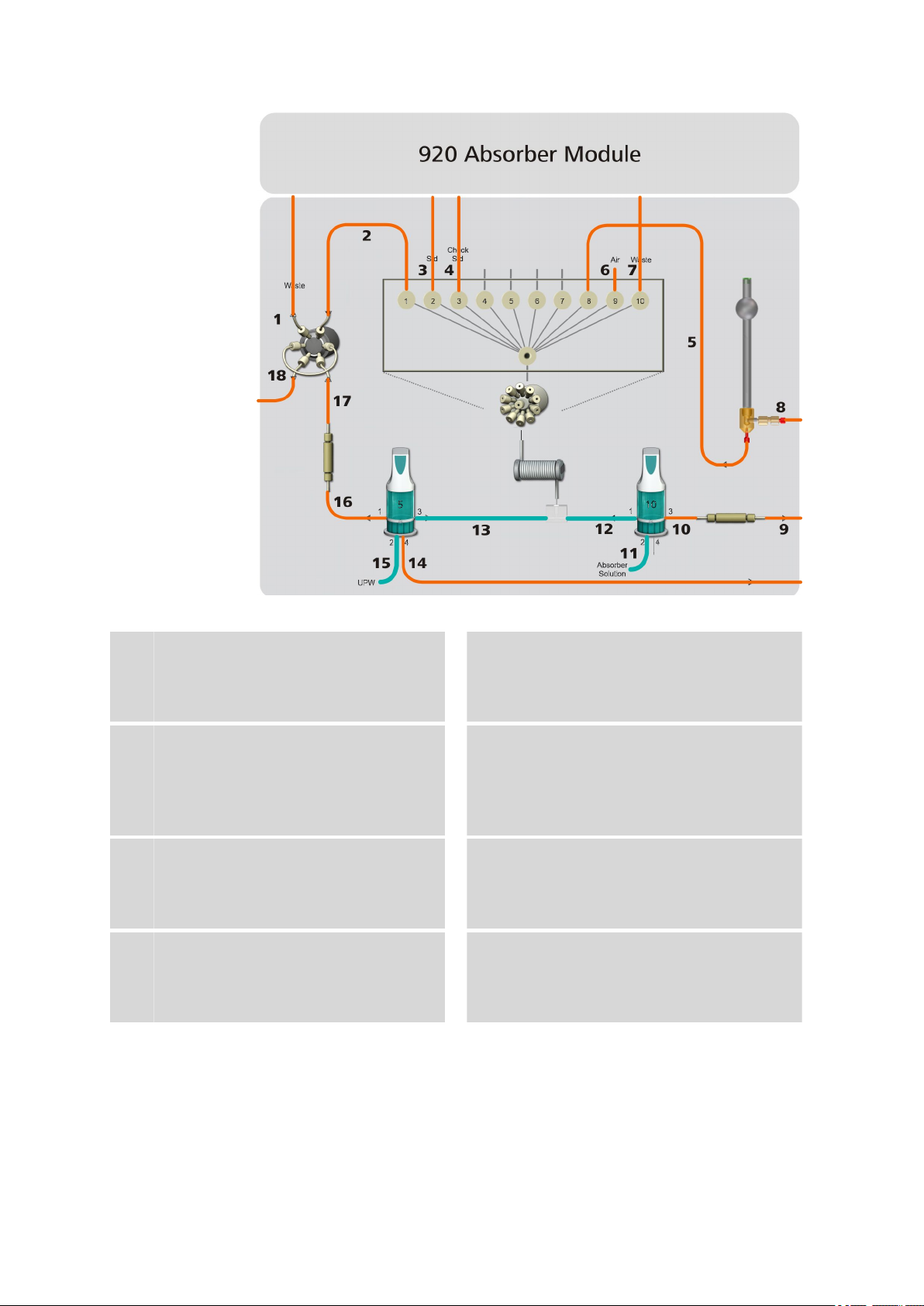
4.4 Dosino for the absorber solution
4 Installation
Figure 10 Installing the Dosino for the absorber solution
PTFE capillary, 0.5 mm ID / 3 m
9
(6.1803.030)
Connection between the Metrosep A Trap 1
- 100/4.0 trap column (6.1014.000) and the
Combustion Module.
FEP tubing M6 for 920, 150 cm
11
(6.1838.020)
Aspiration tubing for the absorber solution.
Connection between the Dosino with the
absorber solution and the bottle with the
absorber solution.
The Dosino for the absorber solution is equipped with a 10 mL dosing unit
and has the following tasks:
■ Dosing the absorber solution.
■ Transferring the absorption solution to the 10-port valve.
PTFE capillary, 0.5 mm ID / 3 m
10
(6.1803.030)
Approx. 20 cm. Connection between the
Dosino with the absorber solution and the
Metrosep A Trap 1 - 100/4.0 trap column
(6.1014.000).
FEP tubing M6 for 920, 9 cm
12
(6.1838.040)
Connection between the Dosino with the
absorber solution and the T connection.
920 Absorber Module
■■■■■■■■
39
Page 48

4.4 Dosino for the absorber solution
Dosing the absorber solution
The absorber solution is dosed for the combustion tube's outlet in the
Combustion Modul. It absorbs the gases from combustion and carries
them to the absorber tube.
■■■■■■■■■■■■■■■■■■■■■■
Transferring the absorption solution to the 10-port valve
Drawing the absorption solution out of the absorber tube.
4.4.1 Assembling the Dosino
Accessories
For this step you need:
■ 800 Dosino (2.800.0010)
■ Dosing unit 10 mL (6.3032.210)
■■■■■■■■
40
Attaching the Dosino on the Dosing Unit
The manual for the 800 Dosino describes how to attach a dosing unit correctly on the 800 Dosino.
920 Absorber Module
Page 49

■■■■■■■■■■■■■■■■■■■■■■
CAUTION
Please read through the correct procedure in the manual for the 800
Dosino before you attach the Dosino on the dosing unit.
Plugging in the connection cable
Route the connection cable for the Dosino for the absorber solution
1
out of the instrument through the cable opening (6-1) in the back
panel.
Plug the plug for the connection cable into the MSB 1 socket.
2
4.4.2 Connecting the ports – Overview
Using ports
The ports on the Dosino for the absorber solution are used as follows:
4 Installation
Port … … is used for … … and is connected to
1 Liquid Handling T connection
2 Aspirating the absorber solution Bottle with absorber solution
3 Dosing the absorber solution Metrosep A Trap 1 - 100/4.0
(6.1014.000) trap column inlet
4 Not used
Accessories The following accessories have to be connected to the Dosino for the
absorber solution:
Port Install this accessory
Port 1
Port 2
Port 3
Port 4 –
FEP tubing M6 for 920, 9 cm (6.1805.040) (10-12)
FEP tubing M6 for 920, 150 cm (6.1838.020) (10-11)
■ PTFE capillary (6.1803.030), approx. 20 cm (10-10)
■ Pressure screw (6.2744.350)
■ Coupling (6.2744.080)
For this step you also need:
920 Absorber Module
■ Thread adapter (6.1618.020)
■ Dosino holder (6.2057.230)
■ Capillary cutter (6.2621.080)
■■■■■■■■
41
Page 50

4.4 Dosino for the absorber solution
2.800.0020
6.3032.210
6.2057.230
6.1618.020
6.1805.040
6.1838.020
6.2744.080
6.2744.350
6.1803.030
(20 cm)
Port 3
Port 1
Port 2
Port 4
■■■■■■■■■■■■■■■■■■■■■■
Accessories
Figure 11 Connect the Dosino for the absorber solution
Connecting port 2
Port 2 is located on the bottom of the Dosino. Port 2 is used for aspirating
the absorber solution.
The following accessories have to be connected at port 2:
Port Install this accessory
Port 2
FEP tubing M6 for 920, 150 cm (6.1838.020) (10-11)
For this step you also need:
■ Thread adapter (6.1618.020)
■ Dosino holder (6.2057.230)
■■■■■■■■
42
920 Absorber Module
Page 51

■■■■■■■■■■■■■■■■■■■■■■
6.1838.020
6.2057.230
6.1618.020
Installing the water aspiration tubing at port 2
1
Threading the Dosino holder thread adapter
Before you can connect the aspiration tubing for the absorber solution, you have to thread the aspiration tubing for the absorber solution through thread adapter and the Dosino holder.
4 Installation
920 Absorber Module
■ Start by threading the FEP tubing through the thread adapter
from below and then through the Dosino holder.
2
Connecting the FEP tubing to port 2
Tighten the FEP tubing on port 2 of the dosing unit.
3
Routing the FEP tubing out of the instrument
Guide the loose end of the FEP tubing out of the 920 Absorber Module through one of the capillary openings on the back panel of the
instrument.
Tightening the Dosino holder on the Dosino for the
absorber solution
Prerequisites:
■■■■■■■■
43
Page 52

4.4 Dosino for the absorber solution
FEP tubing (6.1838.020) is threaded in through the thread adapter
(6.1618.020) and the Dosino holder (6.2057.230) and is connected to
port 2.
■■■■■■■■■■■■■■■■■■■■■■
Tighten the Dosino holder (6.2057.230) with the thread adapter
1
(6.1618.020) on the bottom of the dosing unit.
Next step Connect the ports 1 and 3.
Connecting port 1 and port 3
Accessories
The following accessories have to be connected to these two ports:
Port Install this accessory
Port 1
Port 3
FEP tubing M6 for 920, 9 cm (6.1805.040) (10-12)
■ PTFE capillary (6.1803.030), approx. 20 cm (10-10)
■ Pressure screw (6.2744.350)
■ Coupling (6.2744.080)
■■■■■■■■
44
920 Absorber Module
Page 53

■■■■■■■■■■■■■■■■■■■■■■
Port 1
6.1532.130
6.2744.080
6.2744.350
6.1803.030
Connecting port 1
1
Mounting the FEP tubing
Tighten the FEP tubing on port 1 of the dosing unit.
4 Installation
Connecting port 3
1
Mounting the coupling
■ Push the pressure screw over the end of the PTFE capillary far
enough that a few millimeters of the capillary extend beyond the
tip of the pressure screw.
■ Attach the coupling on the pressure screw and tighten it by hand.
920 Absorber Module
■■■■■■■■
45
Page 54

4.4 Dosino for the absorber solution
Port 3
6.2744.080
6.2744.350
6.1803.030 (20cm)
2
Connecting the PTFE capillary
Tighten the coupling to port 3 of the dosing unit.
■■■■■■■■■■■■■■■■■■■■■■
Next step
Placing the Dosino for the absorber solution into the instrument.
4.4.3 Inserting the Dosino in the instrument
CAUTION
Space is limited in the 920 Absorber Module.
When you insert the fully connected Dosino into the instrument, ensure
that none of the tubing or capillaries are bent or kinked. Turn the Dosino so that the capillaries and tubing can be as straight as possible.
■■■■■■■■
46
920 Absorber Module
Page 55

■■■■■■■■■■■■■■■■■■■■■■
1.
2.
4 Installation
Inserting the Dosino in the instrument
Place the Dosino holder onto the mounting bolts and fix it in place
1
using the knurled screw.
Next step
Connect
capillary/tubing at port
…
1 T connection (see Chapter 4.4.4, page 47)
2 Bottle with the absorber solution (see Chapter 4.4.6, page 52)
3 Connect the Metrosep A Trap 1 – 100/4.0 inlet (see Chapter 4.4.5,
… to
page 49)
4.4.4 Connecting the T connection
The T connection is connected between the Dosino for ultrapure water,
the Dosino for the absorber solution and the transfer tubing.
Accessories
At inlet … Install this accessory
1 FEP tubing M6 for 920, 9 cm (6.1805.040) from Dosino for absorber
solution (7-12)
920 Absorber Module
■■■■■■■■
47
Page 56

4.4 Dosino for the absorber solution
1
2
3
6.1805.040
6.1805.040
6.1808.060
6.1562.130
■■■■■■■■■■■■■■■■■■■■■■
At inlet … Install this accessory
2 FEP tubing M6 for 920, 9 cm (6.1805.040) from Dosino for ultrapure
water (7-13)
3
Transfer tubing (4-2)
Installing the T connection
1
Connecting the FEP tubing
Screw the loose end of the FEP tubing connected to port 3 of the
Dosino for ultrapure water to an inlet (1) on the T connection.
2
Connecting the transfer tubing
Screw the longer end of the transfer tubing to the outlet (3) on the T
connection.
3
Connecting the FEP tubing
Screw the loose end of the FEP tubing connected to port 1 of the
Dosino for the absorber solution to the last inlet (2) on the T connection.
Next step ■ Connect the transfer tubing to the 10-port valve (see Chapter 4.5.1,
page 55).
■■■■■■■■
48
920 Absorber Module
Page 57

■■■■■■■■■■■■■■■■■■■■■■
4.4.5 Connecting the Metrosep A Trap 1
The Metrosep A Trap 1 – 100/4.0 (6.1014.000) trap column continues to
remove the smallest anionic contaminants in the absorber solution. The
use of trap column ensures that the analysis is not distorted by unwanted
contamination.
The Metrosep A Trap 1 – 100/4.0 is inserted between the Dosino for
absorber solution and the T connector CIC (6.7301.210) at the outlet of
the Combustion Module.
The … … is connected to
Inlet Dosino for the absorber solution
Outlet Combustion tube outlet on the Combustion Module
Accessories Connect the following accessories to the trap column:
On … Install this accessory
Inlet ■ Approx. 20 cm of the PTFE capillary (6.1803.030) connected to
port 3 of the Dosino for the absorber solution (10-10)
■ Pressure screw (6.2744.010)
■ Colored sleeve, yellow
4 Installation
Outlet
■ PTFE capillary (6.1803.030) (10-9)
■ Optional: Colored sleeve, yellow
920 Absorber Module
■■■■■■■■
49
Page 58

4.4 Dosino for the absorber solution
6.1803.030
The capillary for the absorber solution is fed into the instrument as follows:
■■■■■■■■■■■■■■■■■■■■■■
Feed the capillary for the absorber solution into the instrument
Figure 12 Feed the capillary for the absorber solution into the instru-
ment
■ Slide a yellow colored sleeve over the capillary far enough that it
1
remains visible outside the instrument.
■ Route one end of the PTFE- capillary (6.1803.030) to the front of
the instrument from the right side of the instrument through the
capillary feed-through between the base tray and the 920
Absorber Module.
■ Thread the end of the capillary through the bottom horizontal
capillary guide on the right inner side wall and then through the
vertical capillary guide from the bottom to the top.
■ Optional: Fasten another yellow colored sleeve to the end of the
capillary.
Connecting the Metrosep A Trap 1 – 100/4.0
NOTE
■■■■■■■■
50
The trap column is sealed with threaded stoppers at both ends.
Remove these threaded stoppers before connecting the capillaries.
920 Absorber Module
Page 59

■■■■■■■■■■■■■■■■■■■■■■
6.1014.000
3
2
4
6.1803.030
6.2744.010
6.1014.000
6.27440.10
6.1803.030 (20 cm)
1
1
4 Installation
CAUTION
Flow can only move through the trap column in one direction. This flow
direction is marked on the column with an engraved arrow.
Be absolutely sure to note this flow direction when connecting the
capillaries.
Threaded stopper
1
Flow direction indicator
3
920 Absorber Module
Column outlet
2
Column inlet
4
1
Removing the threaded stoppers
Remove the threaded stoppers at the inlet and outlet of the Metrosep A Trap 1 – 100/4.0.
2
Connecting the column's inlet
■ Screw the loose end of the PTFE capillary connected to port 3 of
the Dosino for the absorber solution in place on the inlet of the
trap column using a pressure screw (6.2744.010).
■■■■■■■■
51
Page 60

4.4 Dosino for the absorber solution
Insert the Metrosep A Trap 1 – 100/4.0 in the instrument as follows:
■■■■■■■■■■■■■■■■■■■■■■
3
Connecting the column's outlet
■ Screw the PTFE capillary (6.1803.030) with the yellow colored
sleeve (fed in from the right side of the instrument) in place on
the trap column's outlet using a pressure screw (6.2744.010).
Inserting the trap column in the instrument
Fasten the Metrosep A Trap 1 – 100/4.0 in place in the front holding
1
bracket (4-4) of the 920 Absorber Module using the column head.
Next step Connect the loose end of the PTFE capillary, 0.5 mm ID / 3 m
(6.1803.030) to the Combustion Module's outlet (see Chapter 4.10.2,
page 76).
4.4.6 Connecting the bottle with the absorber solution
The bottle with the absorber solution is connected to port 2 of Dosinos 1.
Accessories
For this step you need:
■ Clear glass bottle 2 L (6.1608.070) filled with the absorber solution
■ Bottle attachment (6.1602.160)
■ FEP tubing M6 for 920, 150 cm (6.1838.020) fastened to port 2 of the
Dosino for the absorber solution.
■ Adsorber tube (6.1609.000)
■ Cotton
■ Adsorber granulate
■■■■■■■■
52
920 Absorber Module
Page 61

■■■■■■■■■■■■■■■■■■■■■■
6.1609.000
6.1602.160
6.1608.070
6.1446.080
6.1838.020
6.2023.020
1
2
4 Installation
Connecting the bottle with the absorber solution
Cotton
1
Screw the bottle attachment onto the bottle.
1
Insert a sealing ring from the 6.1602.160 accessory set into the bot-
2
tle attachment's M6 opening.
Adsorber granulate
2
Put the loose end of the FEP tubing through the bottle attachment's
M6 opening and tighten it.
NOTE
The end of the aspiration tubing has to reach to the bottom of the
bottle.
920 Absorber Module
■■■■■■■■
53
Page 62

4.5 10-port valve
Fill the adsorber tube with a little cotton and adsorber granulate and
3
seal it with the plastic cover.
Place the adsorber tube into the large opening of the bottle attach-
4
ment and fasten it in place with the SGJ clip.
Seal the M8 opening with a stopper.
5
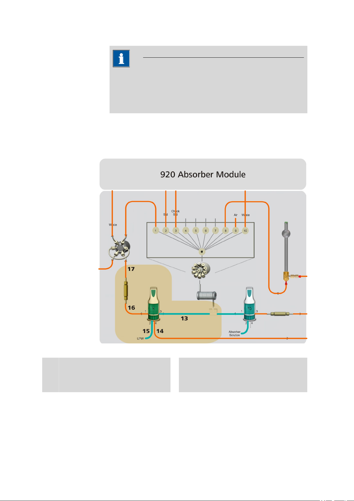
4.5 10-port valve
The 10-port valve can be connected after both Dosinos and the two trap
columns have been installed.
■■■■■■■■■■■■■■■■■■■■■■
■■■■■■■■
54
Figure 13
PEEK capillary, 0.5 mm ID / 15 cm
2
(6.1831.040)
Connection between the 6-port valve and
the 10-port valve.
Connecting the 10-port valve
PTFE capillary, 0.75 mm ID / 3 m
3
(6.1803.160)
Approx. 80 cm. Connection between the
10-port valve and the bottle with the standard solution.
920 Absorber Module
Page 63

■■■■■■■■■■■■■■■■■■■■■■
4 Installation
PTFE capillary, 0.75 mm ID / 3 m
4
(6.1803.160)
Approx. 80 cm. Connection between the
10-port valve and the bottle with the check
standard.
PTFE capillary, 0.75 mm ID / 3 m
6
(6.1803.160)
Approx. 5 cm. For aspirating air segments.
4.5.1 Connecting the ports
The transfer tubing and capillaries for all of the liquids being used are connected to the 10-port valve.
Connectors
The ports of the 10-port valve are used as follows:
Port … … is used for … … is connected to
Central Aspirating and discharging differ-
1 Outlet for sample, standard solu-
5
7
ent solutions
tion, check standard
PTFE capillary, 0.75 mm ID / 3 m
(6.1803.160)
Approx. 60 cm. Connection between the
10-port valve and the absorber tube.
PTFE capillary, 0.75 mm ID / 3 m
(6.1803.160)
Connection between the 10-port valve and
the waste container.
Transfer tubing
6-port valve
2 Inlet for standard solution Bottle with standard solution
3 Inlet for check standard Bottle with check standard
4-7 Not used –
8 Inlet for sample Absorber tube
9 Aspirating air segments –
10 Outlet for waste Waste container
Accessories The following accessories have to be connected to the 10-port valve:
Port Install this accessory
Central ■ Adapter UNF 10/32 outer / M6 inner (6.2744.200)
■ Transfer tubing (6.1562.130)
1
2 ■ PTFE capillary, 0.75 mm ID / 3 m (6.1803.160), approx. 80 cm
3 ■ PTFE capillary, 0.75 mm ID / 3 m (6.1803.160), approx. 80 cm
■ PEEK capillary, 0.5 mm ID / 15 cm (6.1831.040) (13-2)
■ Pressure screw (6.2744.090)
(13-3)
■ Pressure screw (6.2744.090)
(13-4)
■ Pressure screw (6.2744.090)
920 Absorber Module
4-7 Threaded stopper (6.2744.220)
■■■■■■■■
55
Page 64

4.5 10-port valve
6.2744.090
6.1831.040
6.2744.090
6.1803.160
80 cm
6.1803.160
80 cm
6.2744.090
6.27440220
6.2744.220
6.2744.220
6.2744.220
6.2744.090
6.1803.160
60 cm
6.2744.090
6.1803.160
5 cm
6.2744.090
6.1803.160
3 m
6.2744.200
6.1462.130
1
2
3
4
5
6
7
8
9
10
■■■■■■■■■■■■■■■■■■■■■■
Port Install this accessory
8 ■ PTFE capillary, 0.75 mm ID / 3 m (6.1803.160), approx. 60 cm
(13-5)
■ Pressure screw (6.2744.090)
9 ■ PTFE capillary, 0.75 mm ID / 3 m (6.1803.160), approx. 5 cm
(13-6)
■ Pressure screw (6.2744.090)
10
■ PTFE capillary, 0.75 mm ID / 3 m (6.1803.160) (13-7)
■ Pressure screw (6.2744.090)
Connecting the 10-port valve
Connect the ports of the 10-port valve according to the following figure:
NOTE
We recommend connecting the central port first.
56
■■■■■■■■
Figure 14 Connecting the 10-port valve
1
Connecting the central port
■ Screw the adapter in place in the central port.
■ Screw one end of the transfer tubing in place on the adapter.
2
Connecting port 1
■ Screw the PEEK capillary to port 1 using a long pressure screw.
920 Absorber Module
Page 65

■■■■■■■■■■■■■■■■■■■■■■
3
Connecting port 2
■ Cut off a piece from the PTFE capillary, 0.75 mm ID / 3 m
(6.1803.160) that is approx. 80 cm long using the capillary cutter.
■ Screw this piece of capillary in place at port 2 using a long pres-
sure screw.
4
Connecting port 3
■ Cut off a piece from the PTFE capillary, 0.75 mm ID / 3 m
(6.1803.160) that is approx. 80 cm long using the capillary cutter.
■ Screw this piece of capillary in place at port 3 using a long pres-
sure screw.
5
Sealing ports 4 through 7
Ports 4 through 7 are not used.
■ Seal each of ports 4, 5, 6 and 7 with a threaded stopper.
6
Connecting port 8
■ Cut off a piece from the PTFE capillary, 0.75 mm ID / 3 m
(6.1803.160) that is approx. 60 cm long using the capillary cutter.
■ Screw this piece of capillary in place at port 8 using a long pres-
sure screw.
7
Connecting port 9
■ Cut off a piece from the PTFE capillary, 0.75 mm ID / 3 m
(6.1803.160) that is approx. 5 cm long using the capillary cutter.
■ Screw this piece of capillary in place at port 9 using a long pres-
sure screw.
8
Connecting port 10
■ Screw an entire PTFE capillary, 0.75 mm ID / 3 m (6.1803.160) in
place at port 10 using a long pressure screw.
4 Installation
Next step
920 Absorber Module
Connect
capillary/tubing at port
…
1 6-port valve (see Chapter 4.6, page 61)
2 Bottle with standard solution (see Chapter 4.5.2, page 58)
3 Bottle with check standard (see Chapter 4.5.3, page 59)
8 Absorber tube (see Chapter 4.7, page 67)
… to
■■■■■■■■
57
Page 66

4.5 10-port valve
6.1608.050
6.1602.150
6.1602.150
6.1803.160
■■■■■■■■■■■■■■■■■■■■■■
Connect
capillary/tubing at port
…
10 Waste container
… to
4.5.2 Connecting the bottle with the standard solution
The bottle with the standard solution is connected to the 10-port valve.
Accessories For this step you need:
■ Clear glass bottle 100 mL (6.1608.050) filled with standard solution
■ Bottle attachment (6.1602.150), contains 3 pressure screws
Connecting the bottle with the standard solution
■■■■■■■■
58
1
Connecting the aspirating capillary for the standard solution
■ Slide a pressure screw over the loose end of the capillary connec-
ted to port 2 of the 10-port valve (13-3).
■ Thread the capillary through one of the three openings on the
bottle attachment.
■ Screw the bottle attachment onto the bottle.
■ Push the capillary far enough into the bottle that it reaches the
bottom of the bottle. Then fix it in place with a pressure screw.
920 Absorber Module
Page 67

■■■■■■■■■■■■■■■■■■■■■■
4 Installation
Inserting the bottle with the standard solution into the
instrument
Insert the bottle with the standard solution into the bottle holder.
1
4.5.3 Connecting the bottle with the check standard
The bottle with the standard solution is connected to the 10-port valve.
Connecting the bottle with the check standard
Guide the loose end of the capillary (13-4) (connected to port 3 of
1
the 10-port valve) in through a capillary feed-through between the
device and the bottle holder on the side of the instrument.
Fasten the capillary in the bottle containing the check standard.
2
Place the bottle on the bottle holder.
920 Absorber Module
■■■■■■■■
59
Page 68

4.5 10-port valve
2
1
4.5.4 Function of the 10-port valve
The 10-port valve is used for sample preparation. For this, the central port
(15-2) can be connected to the other ten ports one after the other using
the selector (15-1).
The transfer tubing is connected to the central port. Liquids can be aspirated into the transfer tubing by one of the ten ports with the aid of a Dosino and then transported to any other port by reversing the flow.
■■■■■■■■■■■■■■■■■■■■■■
Figure 15 10-port valve – Ports
Selector
1
Can be rotated for selecting the active port.
The selector can rotate in a clockwise or counterclockwise direction. Normally, the shortest path is selected when switching over to a new port.
Secured ports
In order to avoid contamination, any given port can be defined as
"secured". The secured port is moved to during switching only if it is the
target of the switching procedure.
Central port
2
Connected to the transfer tubing.
Example:
■■■■■■■■
60
If the secured port lies along the shortest route during a valve switchover,
then the longer path will automatically be selected.
Switching from port 10 to port 7.
920 Absorber Module
Page 69

■■■■■■■■■■■■■■■■■■■■■■
X
The shorter path leads through ports 9 and 8 (see figure 16, left). If however port 8 is defined as the secured port, then the 10-port valve automatically switches via ports 1 – 2 – 3 – 4 – 5 – 6 (see figure 16, left).
Figure 16 10-port valve – Normal valve switchover and with a secured
4.6 6-port valve
4 Installation
port
The 6-port valve is connected next.
920 Absorber Module
■■■■■■■■
61
Page 70

4.6 6-port valve
■■■■■■■■■■■■■■■■■■■■■■
Figure 17 Connecting the 6-port valve
PTFE capillary, 0.75 mm ID / 3 m
1
(6.1803.160)
Connection between the 6-port valve and
the waste container.
PTFE capillary, 0.5 mm ID / 3 m
17
(6.1803.030)
Approx. 40 cm. Connection between the
Metrosep I Trap 1 - 100/4.0 trap column
(6.1014.200) and the 6-port valve.
4.6.1 Connecting the ports
Connectors
Port … … is used for … … is connected to
1 Inlet for sample, standard solution and check
standard
2 Outlet for waste Waste container
3 Sample loop 6-port valve – Port 6
4 Outlet for sample, standard solution and check
standard
The ports of the 6-port valve are connected as follows:
PEEK capillary, 0.5 mm ID / 15 cm
2
(6.1831.040)
Connection between the 6-port valve and
the 10-port valve.
PTFE capillary, 0.5 mm ID / 3 m
18
(6.1803.030)
Connection between the 6-port valve and
the 930 Compact IC Flex.
10-port valve
Injection valve in the IC instrument
■■■■■■■■
62
920 Absorber Module
Page 71

■■■■■■■■■■■■■■■■■■■■■■
Port … … is used for … … is connected to
5 Inlet for transfer water Metrosep I Trap 1 – 100/4.0 (6.1014.200)
6 Sample loop 6-port valve – Port 3
4 Installation
Accessories
Port Install this accessory
1
2
■ PEEK capillary, 0.5 mm ID / 15 cm (6.1831.040) (17-1)
■ Pressure screw (6.2744.010)
■ PTFE capillary, 0.75 mm ID / 3 m (6.1803.160) (17-1)
■ Pressure screw (6.2744.010)
3 ■ Sample loop 250 µL (6.1825.290)
■ Pressure screw (6.2744.010)
4
■ PTFE capillary, 0.5 mm ID / 3 m (6.1803.030) (17-18)
■ Pressure screw (6.2744.010)
5 ■ PTFE capillary, 0.5 mm ID / 3 m (6.1803.030), approx. 40 cm
(17-17)
■ Pressure screw (6.2744.010)
6 ■ Sample loop 250 µL (6.1825.290)
■ Pressure screw (6.2744.010)
920 Absorber Module
■■■■■■■■
63
Page 72

4.6 6-port valve
6.1803.030
6.1803.160
6.1803.030
6.2744.010
6.2744.010
6.2744.010
6.2744.010
6.1831.040
6.1825.290
1
2
3
4 5
6
■■■■■■■■■■■■■■■■■■■■■■
Connecting the 6-port valve
Figure 18 Connecting the 6-port valve
1
Connecting port 1
■ Tighten the loose end of the PEEK capillary connected to port 1 of
the 10-port valve (17-2) to port 1 of the 6-port valve using a pressure screw.
2
Connecting port 2
■ Push one end of the PTFE capillary, 0.75 mm ID / 3 m
(6.1803.160), (17-1) through a capillary feed-through below the
bottle holder from the back towards the front of the instrument.
■ Push the pressure screw over the end of the PTFE capillary far
enough that approx. 4 mm of the capillary is exposed.
■ Screw the pressure screw in place at port 2 of the 6-port valve.
■ Shorten the other end of the capillary using a capillary cutter so
that it reaches the waste container.
■ Fasten the end to the waste container.
3
Connecting port 4
■ Push one end of the PTFE capillary, 0.5 mm ID / 3 m
(6.1803.030), (17-18) through the cable feed-through at the bottom left on the front of the instrument and then route it up to the
6-port valve through the two capillary guides on the left inside the
instrument.
■■■■■■■■
64
920 Absorber Module
Page 73

■■■■■■■■■■■■■■■■■■■■■■
■ Push the pressure screw over the end of the capillary far enough
that approx. 4 mm of the capillary is exposed.
■ Screw the pressure screw in place at port 4 of the 6-port valve.
4
Connecting port 5
■ Push the pressure screw over the loose end of the capillary con-
nected to the outlet of the Metrosep I Trap 1 – 100/4.0 (17-17)
far enough that approx. 4 mm of the capillary is exposed.
■ Screw the pressure screw in place at port 5 of the 6-port valve.
5
Connecting the sample loop
■ Push the pressure screws far enough over both ends of the sam-
ple loop that approx. 4 mm of the loop is exposed.
■ Tighten the one pressure screw at port 3.
■ Tighten the second pressure screw at port 6.
4.6.2 Mode of operation of the 6-port valve
A sample loop is installed on the 6-port valve; it is used for measuring the
sample amount before it is transferred to the analyzer.
4 Installation
Ports
As its name implies, the 6-port valve has six ports.
Figure 19
Port 1
1
Connected to the 10-port valve. Used as the
inlet for the sample and the standard solution and check standard.
6-port valve – Ports
2
Port 2
For connecting the capillary to the waste
container.
920 Absorber Module
■■■■■■■■
65
Page 74

4.6 6-port valve
1
2
■■■■■■■■■■■■■■■■■■■■■■
Port 3
3
For connecting the sample loop.
Port 5
5
For connecting the capillary from the outlet
of the Metrosep I trap column.
Valve positions
The 6-port valve can have two valve position:
Port 4
4
For connecting the capillary to the ion chromatograph.
Port 6
6
For connecting the sample loop.
Figure 20 6-port valve – Valve positions
Filling
1
■ Filling
2
Injecting
In the Filling position, ports 2 and 3, 4 and 5, and 6 and 1 are connected to each other.
The sample flows through port 1 into the 6-port valve, through the
sample loop and through port 2 out of the 6-port valve into the waste
container.
At the same time, the transfer solution flows through port 5 into the 6port valve and directly back out through port 4.
The sample loop is filled with the sample at this valve position.
■■■■■■■■
66
920 Absorber Module
Page 75

■■■■■■■■■■■■■■■■■■■■■■
■ Injecting
In the Injecting position, ports 1 and 2, 3 and 4, and 5 and 6 are connected to each another.
The transfer solution now flows through port 5 into the 6-port valve,
through the sample loop and back out through port 4. At the same
time, the absorber solution flows through port 1 into the 6-port valve
and directly back out through port 2.
In this valve position, the absorber solution in the sample loop is
flushed to the analyzer together with the transfer solution.
4.7 Absorber tube
4 Installation
Figure 21
PTFE capillary, 0.75 mm ID / 3 m
5
(6.1803.160)
Approx. 60 cm. Connection between the
10-port valve and the absorber tube.
The absorber tube is connected between the Combustion Module and the
10-port valve.
Accessories
920 Absorber Module
The following accessories have to be connected to the absorber tube:
Connect the absorber tube
PTFE capillary, 1/8 in. / 1/16 in. ID / 1.5
8
m
Connection between the absorber tube and
the Combustion Module.
■■■■■■■■
67
Page 76

4.7 Absorber tube
6.2766.000
6.2421.000
■■■■■■■■■■■■■■■■■■■■■■
On the … of
the absorber
tube
top Stopper
bottom Absorber tube holder (6.2766.000) consisting of the holder and a
Install this accessory
sealing ring
Assembling the absorber tube
Assemble the absorber tube according to the following figure:
■■■■■■■■
68
1
Assembling the absorber tube holder
■ Place the sealing ring in the holder.
■ Screw the holder in place on the bottom end of the absorber
tube.
■ Check whether the stopper is in place at the upper end of the
absorber tube.
The following capillaries have to be fastened to the assembled absorber
tube.
920 Absorber Module
Page 77

■■■■■■■■■■■■■■■■■■■■■■
6.1803.160
60 cm
6.2744.010
6.2766.010
6.2824.170
6.1803.130
6.2744.170
4 Installation
On the … of
the absorber
tube
side ■ Inlet valve holder (6.2766.010) consisting of a holder and a nut
bottom ■ Pressure screw (6.2744.010)
Install this accessory
with inlet valve (6.2824.170)
■ PTFE capillary 1/8 in. / 1/16 in. ID / 1.5 m (6.1803.130) (21-8)
■ The loose end of the PTFE capillary 0.75 mm ID / 3 m
(6.1803.160), connected to port 8 of the 10-port valve (21-5).
Connecting the capillaries
1
Installing the check valve
■ Insert the inlet valve into the holder for the inlet valve.
■ Tighten the nut on the holder by hand.
■ Screw the check valve in place on the frit of the holder.
2
Mounting the input capillary
Screw the thicker PTFE capillary (21-8) in place on the check valve
using a pressure screw (6.2744.170).
3
Mounting the outlet capillary
Tighten the loose end of the capillary (21-5) (connected to port 8 of
the 10-port valve) to the bottom of the absorber tube holder using a
pressure screw (6.2744.010).
920 Absorber Module
■■■■■■■■
69
Page 78

4.8 Connecting the drainage tubing and leak sensor
Inserting the absorber tube into the instrument
Insert the absorber tube into the instrument:
■■■■■■■■■■■■■■■■■■■■■■
Hang the absorber tube on the two brackets on the right inner side
1
wall.
Next step
Connect the
Capillary/
tubing at …
side Secure the outlet of the combustion oven (see Chapter 4.10.2, page
… to
76)
4.8 Connecting the drainage tubing and leak sensor
The leak sensor detects leaking liquid that collects in the instrument's base
tray. Liquid that leaks in the bottle holder or in the detector chamber is
routed to the base tray using drainage tubing and is detected there.
If the leak sensor detects a leak in the IC system, the IC instrument is
switched off and a warning is output in the software.
The leak sensor functions properly only if the following preconditions are
met:
■■■■■■■■
70
■ The drainage tubing is connected.
■ The leak sensor connection cable is inserted into the leak sensor con-
nection socket.
■ The Combustion IC system is switched on.
920 Absorber Module
Page 79

■■■■■■■■■■■■■■■■■■■■■■
6.1816.080
6.1816.080
■ The leak sensor is switched to active in the software.
4 Installation
4.8.1 Installing the drainage tubing
Liquid that leaks in the bottle holder flows to the rear of the instrument
and is drained through an opening on the bottle holder. Drainage tubing
has to be mounted at this opening. This drainage tubing guides the leaking liquid to the base tray where the leak sensor is located.
Accessories For this step you need the following parts from the accessory kit: Vario/
Flex Basic (6.5000.000):
■ 2 × silicone tubing (6.1816.080)
You also need scissors.
Connecting the drainage tubing
920 Absorber Module
Attach one end of the silicone tubing to the drainage support on the
1
bottle holder.
Attach the other end of the silicone tubing to the right-side drainage
support on the base tray.
Attach one end of the second piece of silicone tubing to the left-side
2
drainage tubing connection on the base tray.
■■■■■■■■
71
Page 80

4.8 Connecting the drainage tubing and leak sensor
Route the loose end into a waste container.
4.8.2 Connecting the leak sensor
Plugging in the leak sensor connection cable
The leak sensor connection cable is coiled up in the base tray.
■■■■■■■■■■■■■■■■■■■■■■
Pull the leak sensor connection cable out of the base tray as far as
1
needed.
Plug the plug for the leak sensor connection cable into the leak sen-
2
sor connection socket (labeled Leak Sensor).
■■■■■■■■
72
920 Absorber Module
Page 81

■■■■■■■■■■■■■■■■■■■■■■
4.9 Connecting the instrument
4.9.1 Connecting the instrument to the PC
NOTE
The instrument must be switched off when connecting the PC.
1
Connecting the USB cable
Connect the PC connection socket (6-2) of the instrument to a USB
connector of the computer via the USB cable (6.2151.020).
4.9.2 Connecting the instrument to power supply
WARNING
4 Installation
The power supply unit must not get wet. Protect it against the direct
effect of liquids.
Power supply cable
Which power supply cable is supplied depends on the location:
■ 6.2122.020 with plug SEV 12 (Switzerland, …)
■ 6.2122.040 with plug CEE(7), VII (Germany, …)
■ 6.2122.070 with plug NEMA 5-15 (USA, …)
The power supply cable is three-core and provided with a plug with
grounding. If another plug has to be mounted, the yellow/green conductor (IEC standard) must be connected to the protective ground (protection
class I).
1
Connecting the power supply cable
■ Plug the power supply cable into the power socket (6-13).
■ Connect the power supply cable to the power supply.
2
Switching on the instrument
Switch on the instrument using the power switch (6-14).
920 Absorber Module
After switching on, the LED on the front of the instrument flashes
while a system test is carried out and the connection to the software
is established. Once the system test is complete and the connection
to the software has been established, the LED lights up continuously.
■■■■■■■■
73
Page 82

4.10 Connecting the 920 Absorber Module to the remaining components
■■■■■■■■■■■■■■■■■■■■■■
4.10 Connecting the 920 Absorber Module to the remaining components
Three capillaries are routed out at the right side of the Combustion IC system.
■ The capillary connected to port 4 of the Dosino for ultrapure water is
marked with a blue colored sleeve.
■ The capillary connected to the outlet of the Metrosep A Trap 1 –
100/4.0 is marked with a yellow colored sleeve.
■ The thicker capillary installed at the inlet of the absorber tube is routed
out under the door.
4.10.1 Connecting the Combustion Module inlet: water infeed
Connecting the capillary for the water infeed at the inlet of
the combustion tube
1
Feeding the capillary into the Combustion Module
Feed the capillary with the blue colored sleeve into the inside
through the round opening up on the left side wall of the Combustion Module and route it to the right side of the Combustion Module
(see Chapter "Installing the Combustion Module after transportation
or storage" in the Combustion Module operating instructions).
2
Shortening the capillary
Shorten the capillary using the capillary cutter so that it can be connected to the combustion tube's inlet easily.
3
Connecting the capillary
Three connections are located at the combustion tube's inlet:
■■■■■■■■
74
920 Absorber Module
Page 83

■■■■■■■■■■■■■■■■■■■■■■
4 Installation
Figure 22 Combustion tube – Inlet
Water infeed inlet
1
Connection for the capillary with the blue
colored sleeve (7-14).
Oxygen infeed
3
Connection for the oxygen infeed.
■ Plug the capillary into a FAST connector (see Chapter "Replacing
■ Carefully attach the FAST connector to the connection (22-1).
You can find information on connecting the flame sensor, the oxygen infeed and the ABD in the Combustion Module operating
instructions.
Flame sensor connection
2
Connection for the flame sensor.
Sample inlet
4
Solid and liquid samples: inlet for sample
boats.
Gaseous samples: connection of the LPG/
GSS module.
tubing connections" in the Combustion Module operating
instructions).
920 Absorber Module
■■■■■■■■
75
Page 84

4.10 Connecting the 920 Absorber Module to the remaining components
■■■■■■■■■■■■■■■■■■■■■■
4.10.2 Connecting the Combustion Module outlet: Absorber solution
The capillary with the yellow colored sleeve and the thicker capillary are
connected to the CIC T connector in the Combustion Module.
There are 2 connections on the CIC T connector in the Combustion Module:
■■■■■■■■
76
Figure 23
Absorber solution connection
1
Connection for the capillary with the yellow
colored sleeve (7-9).
Peltier cooler
3
For cooling the combustion gases at the
combustion tube's outlet.
Combustion tube – Outlet
T connector CIC (6.7301.210)
2
T connector on the combustion tube's outlet. For feeding the absorber solution in and
removing the combustion gases.
Combustion gases connection
4
Connection for the PTFE capillary, 1/8 in. /
1/16 in. ID / 1.5 m (6.1803.130) (7-8).
920 Absorber Module
Page 85

■■■■■■■■■■■■■■■■■■■■■■
Connecting the capillary for the combustion gases
1
Feeding the capillary into the Combustion Module
■ Push the loose end of the PTFE capillary 1/8 in. / 1/16 in. ID / 1.5
m (6.1803.130) (7-8) through the opening in the right-side door
of the 920 Absorber Module.
■ Guide the capillary through the round opening in the bottom of
the Combustion module into the inside.
2
Shortening the capillary
Shorten the capillary using the capillary cutter so that it can be connected to the CIC T connector's outlet (23-4) easily.
3
Connecting the capillary
■ Insert the capillary into an angled FAST connector (6.7304.000).
■ Carefully attach the FAST connector to the CIC T connector's out-
let (23-4).
4 Installation
Connecting the capillary for the absorber solution
1
Feeding the capillary into the Combustion Module
Guide the loose end of the capillary with the yellow colored sleeve
into the inside through the round opening at the top in the left side
wall.
2
Shortening the capillary
Shorten the capillary using the capillary cutter so that it can be connected to the CIC T connector's outlet (23-1) easily.
3
Connecting the capillary
■ Plug the capillary into a straight FAST connector (6.7304.010) (see
Chapter "Replacing tubing connections" in the Combustion Module operating instructions).
■ Carefully attach the FAST connector to the CIC T connector's out-
let (23-1).
920 Absorber Module
■■■■■■■■
77
Page 86

4.10 Connecting the 920 Absorber Module to the remaining components
4.10.3 Connecting the 930 Compact IC Flex
A capillary is routed out on the left side of the 920 Absorber Module.
This capillary is connected to the injection valve of the 930 Compact IC
Flex.
■■■■■■■■■■■■■■■■■■■■■■
Accessories For this step you need:
■ Capillary cutter (6.2621.080)
Connecting the 930 Compact IC Flex
■ Shorten the end of the capillary using the capillary cutter so that it
1
can be connected to the injection valve of the 930 Compact IC
Flex easily.
■ Connect the end of the capillary to port 1 of the injection valve
(see manual for 930 Compact IC Flex).
NOTE
The process for connecting the respective instruments to a computer or
a power supply is described in the respective manuals:
■ 930 Compact IC Flex manual.
■ 920 Absorber Module manual.
■ Combustion Module operating instructions (on the accompanying
CD).
■ MMS 5000 operating instructions (on the accompanying CD).
■ LPG/GSS Module manual (on the accompanying CD).
■■■■■■■■
78
920 Absorber Module
Page 87

■■■■■■■■■■■■■■■■■■■■■■
5 Start-up
5 Start-up
All of the Combustion IC system components have to be completely
installed before putting the 920 Absorber Module into operation; this
means:
■ The Combustion Module including ABD and optional sampler (MMS
5000) and, if necessary, the LPG/GSS Module is installed according to
the specifications in the Combustion IC operating instructions from
Analytik Jena.
■ The 920 Absorber Module is installed according to the specifications in
the manual for the 920 Absorber Module and is connected to the
Combustion Module.
■ The 930 Compact IC Flex (2.930.2560) is installed according to the
specifications in the manual for the ion chromatograph and is connected to the 920 Absorber Module.
■ The ion chromatograph is connected to a computer where the
MagIC Net software is installed.
Putting the Combustion IC system into operation
1
Starting the software
■ Switch on the PC and start the software MagIC Net.
■ Enter user name and password.
The software starts and shows the Workplace program part.
2
Switching on the instruments
■ Switch on the Combustion Module: the Combustion Oven and
the ABD, the MMS 5000 sampler or the LPG/GSS Module, if it is
present.
■ Switch on the Combustion IC system.
■ Switch on the ion chromatograph.
MagIC Net detects all of the instruments and asks if they are to be
saved to the device table.
■ Confirm all of the prompts with [Yes].
920 Absorber Module
■■■■■■■■
79
Page 88

■■■■■■■■■■■■■■■■■■■■■■
NOTE
It can sometimes happen that an instrument is not automatically
recognized when it is newly connected to an existing system.
When an instrument is not automatically recognized, then the
"basic initialization" has to be run in MagIC Net. Additional information concerning the basic initialization can be found in the
MagIC Net online help or in the MagIC Net manual.
3
Loading the method
Workplace ▶ Run
■ Activate the Equilibration tab.
■ In the Method field, load the Preparation of Combustion IC
method.
4
Starting equilibration
■ Start the equilibration with [Start HW].
The instrument is ready to measure as soon as equilibration has finished.
■■■■■■■■
80
920 Absorber Module
Page 89

■■■■■■■■■■■■■■■■■■■■■■
6 Operation and maintenance
6.1 General
The following chapters describe the care and maintenance tasks that can
be carried out by the user.
6.2 Door
CAUTION
The door is made of PMMA (polymethylmetacrylate). It must never be
cleaned with abrasive media or solvents.
6 Operation and maintenance
Never use the door as a handle.
6.3 Dosino
Information regarding the maintenance of the Dosino can be found in the
Dosino manual enclosed in your delivery. Alternatively, you can also
download it from the Internet at documents.metrohm.com.
6.4 Dosing unit
Information regarding the maintenance of the Dosino can be found in the
Dosino manual enclosed in your delivery. Alternatively, you can also
download it from the Internet at documents.metrohm.com.
CAUTION
920 Absorber Module
■■■■■■■■
81
Page 90

6.5 Metrosep I Trap 1
6.5 Metrosep I Trap 1
Information regarding the maintenance of the Metrosep I Trap 1 can be
found in the leaflet on the trap column enclosed in your delivery. Alternatively, you can also download it from the Internet at docu-
ments.metrohm.com.
6.6 Metrosep A Trap 1
Information regarding the maintenance of the Metrosep A Trap 1 can be
found in the leaflet on the trap column enclosed in your delivery. Alternatively, you can also download it from the Internet at docu-
ments.metrohm.com.
6.7 10-port valve
Check on a regular basis whether the connections of the capillaries are
tight.
■■■■■■■■■■■■■■■■■■■■■■
If you find leaking connections, loosen and reconnect them.
More information about how to handle pressure screws and capillaries
can be found on the Internet at http://www.metrohm.com/com/Support/
Video/.
6.8 6-port valve
Check on a regular basis whether the connections of the capillaries are
tight.
If you find leaking connections, loosen and reconnect them.
More information about how to handle pressure screws and capillaries
can be found on the Internet at http://www.metrohm.com/com/Support/
Video/.
■■■■■■■■
82
920 Absorber Module
Page 91

■■■■■■■■■■■■■■■■■■■■■■
6.1803.160
60 cm
6.2744.010
6.2766.010
6.2824.170
6.1803.130
6.2744.170
6.9 Absorber tube
The absorber tube requires maintenance if the check valve and the
absorber tube holder clog up due to sooting resulting from deflagration in
the combustion tube.
The absorber tube holder (6.2766.000) and the inlet valve (6.2824.170) in
the check valve must be exchanged.
6 Operation and maintenance
Exchanging the inlet valve
1
Disconnecting the inlet capillary
Unscrew the pressure screw (6.2744.170) from the check valve.
2
Unscrewing the check valve holder
Unscrew the check valve holder (6.2766.010) from the absorber tube
holder.
3
Replacing the inlet valve
■ Disassemble the check valve holder by unscrewing it.
■ Remove the inlet valve.
■ Insert the new inlet valve (see figure).
■ Reassemble by screwing the parts of the check valve together.
920 Absorber Module
■■■■■■■■
83
Page 92

6.9 Absorber tube
■■■■■■■■■■■■■■■■■■■■■■
Exchanging the absorber tube holder
1
Unscrewing the outlet capillary
On the bottom side, unscrew the pressure screw from the absorber
tube holder.
2
Unscrewing the check valve holder
Unscrew the check valve holder (6.2766.010) from the absorber tube
holder.
3
Replacing the absorber tube holder
■ Unscrew the absorber tube holder from the absorber tube.
■ Place a new sealing ring in the new absorber tube holder.
■ On the bottom, screw the new absorber tube holder to the
absorber tube.
4
Tightening the check valve holder
Screw the check valve holder with the new inlet valve to the side of
the absorber tube holder.
5
Fastening the inlet capillary again
Screw the inlet capillary (6.1803.130) to the check valve again using
the pressure screw (6.2744.170).
6
Mounting the outlet capillary
Tighten the loose end of the capillary (6.1803.160) (connected to
port 8 of the 10-port valve) to the bottom of the absorber tube
holder using a pressure screw (6.2744.010).
■■■■■■■■
84
920 Absorber Module
Page 93

■■■■■■■■■■■■■■■■■■■■■■
6 Operation and maintenance
6.10 Quality Management and qualification with Metrohm
Quality management
Metrohm offers you comprehensive support in implementing quality management measures for instruments and software. Further information on
this can be found in the brochure "Metrohm Quality Management"
available from your local Metrohm representative.
Qualification
Please contact your local Metrohm representative for support in qualification of instruments and software. The Installation Qualification (IQ)
and Operational Qualification (OQ) are offered by Metrohm representatives as a service. They are carried out by trained employees using standardized qualification documents and in accordance with the currently
applicable requirements of the regulated industry. Further information on
this can be found in the brochure "Analytical Instrument Qualifica-
tion – Confidence in quality with IQ/OQ".
Maintenance
The electronic and mechanical functional groups of Metrohm instruments
can and should be checked by specialist personnel from Metrohm as part
of a regular preventive maintenance schedule. Please ask your local
Metrohm representative regarding the precise terms and conditions
involved in concluding a corresponding maintenance agreement. Further
information on this can be found in the brochure "Metrohm Care Con-
tracts – Protect your investment the smart way" available from your
local Metrohm representative.
920 Absorber Module
■■■■■■■■
85
Page 94

7.1 Problems and their solutions
7 Troubleshooting
7.1 Problems and their solutions
Problem Cause Remedy
■■■■■■■■■■■■■■■■■■■■■■
Combustion Module
does not work.
Dosinos do not dose
correctly.
The Combustion Module is
recognized by Magic Net™
and entered in the device
list, even if it has not been
switched on yet.
The determination has
been canceled. The Dosinos' status is not defined.
Switch on all instruments of the Combustion
Module.
Run the method Preparation of Combus-
tion IC.
7.2 Problems with the Dosino
If you should experience problems with the Dosino, you can find information on troubleshooting in the manual for the 800 Dosino enclosed in the
delivery. Alternatively, you can also download it from the Internet at docu-
ments.metrohm.com.
7.3 Problems with the dosing units
If you should experience problems with the dosing units, you can find
information on troubleshooting in the manual for the 800 Dosino
enclosed in the delivery. Alternatively, you can also download it from the
Internet at documents.metrohm.com.
■■■■■■■■
86
920 Absorber Module
Page 95

■■■■■■■■■■■■■■■■■■■■■■
8 Technical specifications
8.1 Reference conditions
The technical data listed in this Chapter refers to the following reference
conditions:
8 Technical specifications
Ambient temperature
Instrument status > 40 minutes in operation (equilibrated)
+25 °C (± 3 °C)
8.2 Ambient conditions
Operation
Ambient temperature
Humidity 20…80 % relative humidity
Storage
Ambient temperature
Transport
Ambient temperature
+5…+45 °C
–20…+70 °C
–40…+70 °C
8.3 Housing
Dimensions
Width 302 mm
Height 562 mm
Depth 368 mm
Weight
Without accessories
With Dosinos 16.2 kg
Material of base
tray, housing and
bottle holder
920 Absorber Module
15.0 kg
Polyurethane hard foam (PUR) with flame retardation for fire class
UL94V0, CFC-free, coated
■■■■■■■■
87
Page 96

8.4 Dosino
Operating elements
Indicators LED power display
On/off switch On the rear of the instrument
8.4 Dosino
Please refer to the manual for the Dosino enclosed in the delivery for
information regarding the technical specifications of the Dosino. Alternatively, you can also download it from the Internet at docu-
ments.metrohm.com.
8.5 10-port valve
■■■■■■■■■■■■■■■■■■■■■■
Connections
Resistance to solvents
Switching time typ.100 ms
Pressure resistance 2.0 MPa (20 bar)
1 out of 10
No restrictions
Valve function prevents damage at overpressure
8.6 6-port valve
Actuator switching time
Maximum operating pressure
Material PEEK
typ.100 ms
35 MPa (350 bar)
■■■■■■■■
88
920 Absorber Module
Page 97

■■■■■■■■■■■■■■■■■■■■■■
8.7 Absorber tube
Material Glass
Dimensions
Length 240 mm
Maximum volume 8 mL
8.8 Leak sensor
8 Technical specifications
Type
Electronic, no calibration necessary
8.9 Power connection
Required voltage
Required frequency
Power consumption
Power supply unit ■ Up to 300 W maximum, electronically monitored
100 - 240 V ± 10% (autosensing)
50 - 60 Hz ± 3 Hz (autosensing)
■ 65 W for typical analysis application
■ internal fuse 3.15 A
8.10 Interfaces
USB
Inlet 1 plug type B (for connection to PC)
Outlet 2 plugs, type A (for connection to further instruments equipped with
USB connector)
MSB 2 Mini-DIN plugs, 8-pin (female) (for Dosinos)
CAUTION
When connecting an instrument to the MSB connector you must
switch off the 920 Absorber Module.
Extension Module
Detector 2 DSUB 15-pin high density plugs (female)
Leak sensor 1 jack plug
920 Absorber Module
1 DSUB 15-pin (female)
■■■■■■■■
89
Page 98

8.11 Safety specification
■■■■■■■■■■■■■■■■■■■■■■
8.11 Safety specification
This instrument fulfills the following electrical safety requirements:
CE marking in accordance with the EU directives:
■ 2006/95/EC (Low Voltage Directive, LVD)
■ 2004/108/EC (EMC Directive, EMC)
Federal Inspectorate for Heavy Current Installations ESTI (Accreditation
Number SCESp 033)
■ Safety mark for certification type 2 in accordance with NEV (type
testing with market monitoring, EMC conformity)
Design and testing According to EN/IEC/UL 61010-1, CSA-C22.2 No. 61010-1, protection
class I, EN/IEC 60529, degree of protection IP20.
Safety instructions:
This document contains safety instructions which have to be followed
by the user in order to ensure safe operation of the instrument.
8.12 Electromagnetic compatibility (EMC)
Emission
Immunity ■ EN/IEC 61326-1
■ EN/IEC 61326-1
■ EN/IEC 61000-6-3
■ EN 55011 / CISPR 11
■ EN/IEC 61000-6-2
■ EN/IEC 61000-4-2
■ EN/IEC 61000-4-3
■ EN/IEC 61000-4-4
■ EN/IEC 61000-4-5
■ EN/IEC 61000-4-6
■ EN/IEC 61000-4-11
■ EN/IEC 61000-4-14
■ EN/IEC 61000-4-28
■■■■■■■■
90
920 Absorber Module
Page 99

■■■■■■■■■■■■■■■■■■■■■■
9 Warranty (guarantee)
Metrohm guarantees that the deliveries and services it provides are free of
defects in materials, design or manufacturing.
The general warranty period is 36 months (exclusions below) from the
date of delivery, or 18 months in the event of continuous operation. The
warranty remains valid on the condition that the servicing is provided by a
service organization authorized by Metrohm at defined intervals and with
a defined scope.
The warranty period for anion suppressors of the type "MSM" is 120
months from the date of delivery or 60 months in the case of continuous
operation.
The warranty period for IC separation columns is 90 days after start-up.
For third-party components that are recognizable as such, the manufacturer's warranty regulations apply.
9 Warranty (guarantee)
For instruments sold under the Metrohm NIRSystems brand, a full 16month warranty is applicable. In the event of continuous operation, the
warranty period is reduced by half.
Consumables and materials with limited storage life and glass breakage in
the case of electrodes or other glass parts are excluded from the warranty.
Warranty claims cannot be asserted if the ordering party has failed to
meet its payment obligations according to schedule.
During the warranty period, Metrohm undertakes either to replace free of
charge or to credit the purchaser for any modules or components that can
be shown to be faulty. Any transport or customs fees that may apply are
the responsibility of the ordering party.
The precondition for this is that the ordering party has to specify the article number, the article designation, an adequate error description, the
delivery date and (if applicable) the serial number or chip data in the Support Tracker. Metrohm then decides whether a replacement or a credit
note is to be issued or whether the faulty part has to be returned using
the Return Material Authorization (RMA). If a replacement or credit note is
issued, the ordering party undertakes to store the faulty part for at least
24 months in accordance with the current storage directives (in compliance with ESD guidelines) and to hold it in readiness for onsite inspection
or for return shipment to Metrohm. Metrohm reserves the right to invoice
the ordering party for these articles, including retroactively, in the event of
noncompliance with these preconditions.
920 Absorber Module
■■■■■■■■
91
Page 100

■■■■■■■■■■■■■■■■■■■■■■
The same warranty periods that are specified for a corresponding new
part apply to parts that are replaced or repaired within the above-mentioned warranty periods. However, replacement or repair of a part does
not extend the warranty period of the entire system.
Deficiencies arising from circumstances that are not the responsibility of
Metrohm, such as improper storage or improper use, etc., are expressly
excluded from the warranty.
Metrohm also offers a 120-month spare parts availability guarantee and a
60-month PC software support warranty, calculated from the date on
which the product is withdrawn from the market. The content of this warranty is the ability of the customer to obtain functioning spare parts or
appropriate software support at market prices during the time of the warranty period. This does not apply for software products sold under the
Metrohm NIRSystems brand.
If Metrohm AG is unable to meet this obligation due to circumstances
beyond the control of Metrohm AG, then the ordering party shall be
offered alternative solutions at preferential conditions.
■■■■■■■■
92
920 Absorber Module
 Loading...