

Page 1
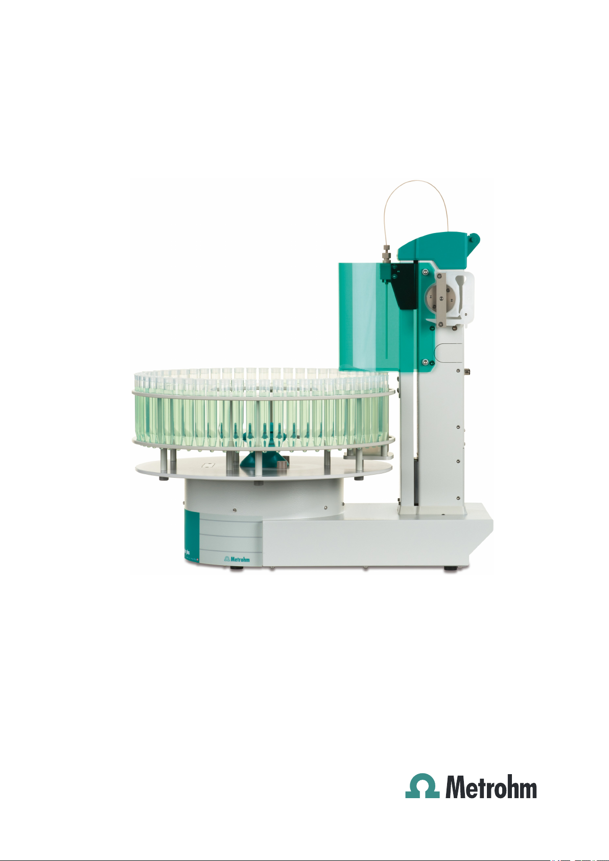
919 IC Autosampler plus
Manual
8.919.8003EN
Page 2

Page 3

Metrohm AG
CH-9100 Herisau
Switzerland
Phone +41 71 353 85 85
Fax +41 71 353 89 01
info@metrohm.com
www.metrohm.com
919 IC Autosampler plus
8.919.8003EN
Manual
10.2013 dm/fpe
Page 4

Teachware
Metrohm AG
CH-9100 Herisau
teachware@metrohm.com
This documentation is protected by copyright. All rights reserved.
Although all the information given in this documentation has been
checked with great care, errors cannot be entirely excluded. Should you
notice any mistakes please send us your comments using the address
given above.
Documentation in additional languages can be found on
http://documents.metrohm.com.
Page 5

■■■■■■■■■■■■■■■■■■■■■■
Table of contents
1 Introduction 1
1.1 Area of application ............................................................... 1
1.2 Instrument description ......................................................... 1
1.3 Intended use ......................................................................... 2
1.4 About the documentation ................................................... 2
1.4.1 Symbols and conventions ........................................................ 2
1.5 Safety instructions ................................................................ 3
1.5.1 General notes on safety ........................................................... 3
1.5.2 Electrical safety ........................................................................ 3
1.5.3 Tubing and capillary connections ............................................. 4
1.5.4 Personnel safety ...................................................................... 5
1.6 Recycling and disposal ......................................................... 6
Table of contents
2 Overview of the instrument 7
2.1 Front ...................................................................................... 7
2.2 Rear ........................................................................................ 8
2.3 Connector strip ..................................................................... 9
2.4 Sample rack ........................................................................... 9
2.5 Peristaltic pump .................................................................. 10
3 Installation 11
3.1 Setting up the instrument .................................................. 11
3.1.1 Packaging .............................................................................. 11
3.1.2 Checks .................................................................................. 11
3.1.3 Location ................................................................................ 11
3.2 Connecting the power supply cable ................................. 11
3.3 Installing the sample needle .............................................. 12
3.4 Installing the peristaltic pump .......................................... 14
3.5 Filtration cell holder ........................................................... 17
3.6 Mounting the safety shield ................................................ 17
919 IC Autosampler plus
3.7 Connecting a computer ...................................................... 18
3.8 Connecting MSB devices .................................................... 20
3.8.1 Connecting a dosing device ................................................... 21
3.8.2 Connecting a stirrer or titration stand .................................... 22
3.8.3 Connecting a Remote Box ..................................................... 23
■■■■■■■■
III
Page 6

Table of contents
■■■■■■■■■■■■■■■■■■■■■■
4 Operation and maintenance 25
4.1 General ................................................................................ 25
4.2 Filter ..................................................................................... 25
4.3 Peristaltic pump .................................................................. 26
4.4 Pump tubings ...................................................................... 26
4.5 Quality Management and qualification with
Metrohm ............................................................................. 28
5 Troubleshooting 29
5.1 Problems and their solutions ............................................. 29
6 Appendix 30
6.1 Lift settings ......................................................................... 30
6.2 Remote interface ................................................................ 31
6.2.1 Pin assignment of the remote interface .................................. 31
7 Technical specifications 33
7.1 Lift and turntable ............................................................... 33
7.2 Two-channel peristaltic pump ........................................... 33
7.3 Interfaces and connectors ................................................. 33
7.4 Mains connection ............................................................... 34
7.5 Safety specifications ........................................................... 34
7.6 Electromagnetic compatibility (EMC) ................................ 34
7.7 Ambient temperature ......................................................... 35
7.8 Reference conditions .......................................................... 35
7.9 Dimensions .......................................................................... 35
8 Warranty (guarantee) 36
9 Accessories 38
Index 40
■■■■■■■■
IV
919 IC Autosampler plus
Page 7

■■■■■■■■■■■■■■■■■■■■■■
Table of figures
Figure 1 Front 919 IC Autosampler plus .......................................................... 7
Figure 2 Rear 919 IC Autosampler plus ........................................................... 8
Figure 3 Connector strip 919 IC Autosampler plus ........................................... 9
Figure 4 Attaching a sample rack .................................................................... 9
Figure 5 Peristaltic pump ............................................................................... 10
Figure 6 Connecting the power supply cable ................................................. 11
Figure 7 Installing the needle ........................................................................ 12
Figure 8 Installing the pump tubing .............................................................. 14
Figure 9 Inserting the tubing cartridge .......................................................... 15
Figure 10 Installing the filtration cell holder ..................................................... 17
Figure 11 Mounting the safety shield .............................................................. 18
Figure 12 Connecting the computer ................................................................ 19
Figure 13 Connecting a dosing device ............................................................. 22
Figure 14 Connecting an MSB stirrer ............................................................... 22
Figure 15 Connecting the propeller stirrer to the titration stand ...................... 23
Figure 16 Connecting the Remote Box ............................................................ 23
Figure 17 Pump tubing connection – Replacing the filter ................................. 25
Figure 18 Adjusting the needle ....................................................................... 30
Figure 19 Connectors of the remote box ......................................................... 31
Figure 20 Pin assignment of the remote socket and plug ................................ 31
Table of figures
919 IC Autosampler plus
■■■■■■■■
V
Page 8

Page 9

■■■■■■■■■■■■■■■■■■■■■■
1 Introduction
1.1 Area of application
The 919 IC Autosampler plus is an autosampler with a wide variety of
applications. It offers the option of fully automated sample series processing. In addition to this capability, the 919 IC Autosampler plus can be supplemented to include the functionality for Inline Ultrafiltration or Inline
Dialysis.
Thanks to its proven USB interface, the 919 IC Autosampler plus can be
integrated into Metrohm instrument systems in a flexible manner. The
instrument is always controlled by means of a high-performance PC software, e.g. MagIC Net™ from Metrohm.
1.2 Instrument description
1 Introduction
The 919 IC Autosampler plus has the following features:
■ Turntable with interchangeable sample rack. A single-row sample rack
is included in the scope of delivery.
■ Tower with a robust lift. The lift is equipped with a working head to
which a needle holder can be attached.
■ Two-channel peristaltic pump.
■ Three MSB connectors (Metrohm Serial Bus), each for controlling an
800 Dosino, an 801 Stirrer or a Remote Box, etc.
■ Two USB connectors, with which e.g. printers, keyboards, barcode
readers or additional devices, such as Dosing Interfaces, etc., can be
directly connected.
■ Two connectors for a peristaltic or a membrane pump.
■ Stirrer connector on the tower, for propeller stirrer or magnetic stirrer.
919 IC Autosampler plus
■■■■■■■■
1
Page 10
1.3 Intended use
1.3 Intended use
The 919 IC Autosampler plus is designed for usage as an automation system in analytical laboratories. It is not suitable for usage in biochemical,
biological or medical environments in its basic equipment version.
The present instrument is suitable for processing chemicals and flammable
samples. Usage of the 919 IC Autosampler plus therefore requires the user
to have basic knowledge and experience in handling toxic and caustic
substances. Knowledge with respect to the application of the fire prevention measures prescribed for laboratories is also mandatory.
1.4 About the documentation
CAUTION
Please read through this documentation carefully before putting the
instrument into operation. The documentation contains information
and warnings which the user must follow in order to ensure safe operation of the instrument.
■■■■■■■■■■■■■■■■■■■■■■
1.4.1 Symbols and conventions
The following symbols and formatting may appear in this documentation:
Method Dialog text, parameter in the software
File ▶ New Menu or menu item
[Next] Button or key
Cross-reference to figure legend
The first number refers to the figure number, the second to the instrument part in the figure.
Instruction step
Carry out these steps in the sequence shown.
WARNING
This symbol draws attention to a possible life-threatening hazard or risk of injury.
WARNING
This symbol draws attention to a possible hazard due
to electrical current.
■■■■■■■■
2
919 IC Autosampler plus
Page 11
■■■■■■■■■■■■■■■■■■■■■■
1.5 Safety instructions
1 Introduction
WARNING
This symbol draws attention to a possible hazard due
to heat or hot instrument parts.
WARNING
This symbol draws attention to a possible biological
hazard.
CAUTION
This symbol draws attention to possible damage to
instruments or instrument parts.
NOTE
This symbol highlights additional information and
tips.
1.5.1 General notes on safety
WARNING
This instrument may only be operated in accordance with the specifications in this documentation.
This instrument has left the factory in a flawless state in terms of technical
safety. To maintain this state and ensure non-hazardous operation of the
instrument, the following instructions must be observed carefully.
1.5.2 Electrical safety
The electrical safety when working with the instrument is ensured as part
of the international standard IEC 61010.
WARNING
Only personnel qualified by Metrohm are authorized to carry out service
work on electronic components.
919 IC Autosampler plus
■■■■■■■■
3
Page 12
1.5 Safety instructions
■■■■■■■■■■■■■■■■■■■■■■
WARNING
Never open the housing of the instrument. The instrument could be
damaged by this. There is also a risk of serious injury if live components
are touched.
There are no parts inside the housing which can be serviced or replaced
by the user.
Mains voltage
WARNING
An incorrect mains voltage can damage the instrument.
Only operate this instrument with a mains voltage specified for it (see
rear panel of the instrument).
Protection against electrostatic charges
WARNING
Electronic components are sensitive to electrostatic charges and can be
destroyed by discharges.
Do not fail to pull the mains cable out of the mains connection socket
before you set up or disconnect electrical plug connections at the rear
of the instrument.
1.5.3 Tubing and capillary connections
CAUTION
Leaks in tubing and capillary connections are a safety risk. Tighten all
connections well by hand. Avoid applying excessive force to tubing
connections. Damaged tubing ends lead to leakage. Appropriate tools
can be used to loosen connections.
Check the connections regularly for leakage. If the instrument is used
mainly in unattended operation, then weekly inspections are mandatory.
■■■■■■■■
4
919 IC Autosampler plus
Page 13
■■■■■■■■■■■■■■■■■■■■■■
1.5.4 Personnel safety
Wear protective goggles and working clothes suitable for laboratory
work while operating the 919 IC Autosampler plus. It is also advisable
to wear gloves when caustic liquids are used or in situations where
glass vessels could break.
Always install the safety shield supplied with the equipment before
using the instrument for the first time. Pre-installed safety shields are
not allowed to be removed.
The 919 IC Autosampler plus may not be operated without a safety
shield!
1 Introduction
WARNING
WARNING
WARNING
Personnel are not permitted to reach into the working area of the
instrument while operations are running!
A considerable risk of injury exists for the user.
WARNING
In the event of a possible blockage of a drive, the mains plug must be
pulled out of the socket immediately. Do not attempt to free jammed
sample vessels or other parts while the device is switched on. Blockages
can only be cleared when the instrument is in a voltage-free status; this
action generally involves a considerable risk of injury.
WARNING
The 919 IC Autosampler plus is not suitable for utilization in biochemical, biological or medical environments in its basic equipment version.
919 IC Autosampler plus
Appropriate protective measures must be implemented in the event
that potentially infectious samples or reagents are being processed.
■■■■■■■■
5
Page 14

1.6 Recycling and disposal
1.6 Recycling and disposal
This product is covered by European Directive 2002/96/EC, WEEE – Waste
from Electrical and Electronic Equipment.
The correct disposal of your old equipment will help to prevent negative
effects on the environment and public health.
More details about the disposal of your old equipment can be obtained
from your local authorities, from waste disposal companies or from your
local dealer.
■■■■■■■■■■■■■■■■■■■■■■
■■■■■■■■
6
919 IC Autosampler plus
Page 15

■■■■■■■■■■■■■■■■■■■■■■
1
2
3
4
5
2 Overview of the instrument
2.1 Front
2 Overview of the instrument
Figure 1 Front 919 IC Autosampler plus
Safety shield
1
Peristaltic pump
3
Retaining plate
5
919 IC Autosampler plus
Sample rack (6.2041.510)
2
Lift with needle adapter
4
■■■■■■■■
7
Page 16

2.2 Rear
1
2
3
4
5
2.2 Rear
■■■■■■■■■■■■■■■■■■■■■■
Figure 2 Rear 919 IC Autosampler plus
Warning symbols
1
(see Chapter 1.5.4, page 5)
Stirrer connector
3
For propeller stirrer (802 Stirrer) and magnetic stirrer (741 Magnetic Stirrer)
Connector strip
5
Details (see Chapter 2.3, page 9)
Pump connectors
2
M8 connector for external pumps
786 Swing Head connector
4
■■■■■■■■
8
919 IC Autosampler plus
Page 17

■■■■■■■■■■■■■■■■■■■■■■
USB 2
USB 1
Contr.
MSB 1
MSB 2
MSB 3
Made by Metrohm
Herisau Switzerland
P: 115W U: 100 - 240 V f: 50 - 60 Hz
WARNING - Fire Hazard -
For continued protection replace only
with the same type and rating of fuse
Nr.
1 2 3 4 5
2.3 Connector strip
Figure 3 Connector strip 919 IC Autosampler plus
2 Overview of the instrument
USB connectors
1
MSB connectors
3
For stirrers, dosing devices, etc.
Type plate
5
2.4 Sample rack
Attaching a rack
Attach the sample rack in such a way that the guide pins of the turntable
engage through the guide openings in the base of the rack.
Controller connector
2
For the connection to the PC
Mains connection
4
Figure 4
Attaching a sample rack
The sample rack has a handle with a clamping screw. With this, the rack
can be fixed on the turntable by rotating in clockwise direction.
919 IC Autosampler plus
■■■■■■■■
9
Page 18

2.5 Peristaltic pump
1
2
3
4
5
6
After the sample rack has been attached, the rack must be initialized
with the Rack initialization function in the control software ("Manual
Operation"), so that the magnet code of the rack can be recognized.
Automatic recognition of the rack type is only possible when the rack is
rotated into the starting position.
2.5 Peristaltic pump
The peristaltic pump can be used as a 1-channel or 2-channel pump. One
or two 6.2755.000 tubing cartridges can be mounted.
■■■■■■■■■■■■■■■■■■■■■■
NOTE
Figure 5
Mounting bolt
1
For engaging the tubing cartridge
Contact pressure lever
3
For regulating the contact pressure
Snap-action lever
5
10
For loosening the tubing cartridge
■■■■■■■■
Peristaltic pump
6.2755.000 tubing cartridge
2
For 6.1826.XX0 pump tubings
Retaining bracket
4
Pump drive
6
Roller head with contact pressure rollers
919 IC Autosampler plus
Page 19

■■■■■■■■■■■■■■■■■■■■■■
P: 115W U: 100 - 240 V f: 50 - 60 Hz
Nr.
3 Installation
3.1 Setting up the instrument
3.1.1 Packaging
The instrument is supplied in highly protective special packaging together
with the separately packed accessories. Keep this packaging, as only this
ensures safe transportation of the instrument.
3.1.2 Checks
Immediately after receipt, check whether the shipment has arrived complete and without damage by comparing it with the delivery note.
3.1.3 Location
The instrument has been developed for operation indoors and may not be
used in explosive environments.
3 Installation
Place the instrument in a location of the laboratory which is suitable for
operation, free of vibrations, protected from corrosive atmosphere, and
contamination by chemicals.
The instrument should be protected against excessive temperature fluctuations and direct sunlight.
3.2 Connecting the power supply cable
WARNING
This instrument may only be operated with the supply voltages specified
(see rear of the instrument).
Protect the connection sockets against moisture.
919 IC Autosampler plus
Figure 6
Connecting the power supply cable
■■■■■■■■
11
Page 20

3.3 Installing the sample needle
1
2
3
4
5
6
3.3 Installing the sample needle
Needles made of zirconium oxide or PEEK can be used for aspirating samples.
WARNING
When a 6.1835.050 sample needle or a blunt PEEK needle is used, no
stoppers are permitted to be used on the sample vessels. These stop-
pers cannot be penetrated by such needles. The needle can become
damaged if this is attempted! Perforated stoppers can be used with
double-bevel needles.
■■■■■■■■■■■■■■■■■■■■■■
Figure 7
PTFE capillary or PEEK capillary
1
6.1803.070 or 6.1831.050 / 6.1831.060 /
6.1831.080.
Pressure screw
3
12
4.766.4320 (part of 6.2833.030).
Needle holder (6.2833.030)
5
■■■■■■■■
Installing the needle
2
4
6
PEEK pressure screw
6.2744.070
Ferrule
Sample needle
6.2846.010 (made of zirconium oxide) or
6.1835.020 / 6.1835.040 / 6.1835.050
(made of PEEK).
919 IC Autosampler plus
Page 21

■■■■■■■■■■■■■■■■■■■■■■
This is how you install the needle and the capillary:
1
Removing the pressure screw
Loosen and remove the pressure screw (7-3) screwed onto the needle holder.
2
Inserting the needle
■ Insert the needle from above partway into the opening of the
needle holder (7-5).
■ Slide the PEEK ferrule (7-4) over the needle from above. The nar-
row side of the seal must face upwards.
3
Fastening the needle
■ Screw the pressure screw (7-3) into the needle holder. Lightly
push the needle upwards from below during the process.
■ Tighten the pressure screw in the needle holder by hand (do not
use tools!).
4
Connecting the capillary
■ Slide the 6.2744.070 PEEK pressure screw (7-2) over the end of
the capillary.
■ Manually tighten the PEEK pressure screw with the capillary to the
pressure screw of the needle holder. The capillary must be pushed
in while doing so.
3 Installation
919 IC Autosampler plus
■■■■■■■■
13
Page 22

3.4 Installing the peristaltic pump
1 2 3 4 5 6 7 8 1
9 10 3
6.2744.160
3.4 Installing the peristaltic pump
■■■■■■■■■■■■■■■■■■■■■■
Figure 8 Installing the pump tubing
PEEK pressure screws, short
1
(6.2744.070)
Stopper
3
The colors of the stoppers indicate the inner
diameter of the pump tubing.
Contact pressure lever
5
Adapter
7
Pump tubing
9
Tubing olive (6.2744.030)
2
Tubing cartridge (6.2755.000)
4
Union nut
6
Tubing olive
8
Snap-action lever
10
Mount the pump tubing as follows:
1
Remove the tubing cartridge
Release the tubing cartridge from the cartridge holder by pressing
the snap-action lever and unhooking it from the mounting bolts
(5-1).
2
Insert the pump tubing
■ Press the contact pressure lever all the way down.
■ Place the pump tubing in the tubing cartridge. The stoppers (8-3)
must snap into the corresponding holder of the tubing cartridge.
■■■■■■■■
14
919 IC Autosampler plus
Page 23

■■■■■■■■■■■■■■■■■■■■■■
3 Installation
3
Connect the aspiration side
Place a 6.2744.030 tubing olive (8-2) on the aspiration side of the
pump tubing.
4
Connect the pressure side
■ Slide the union nut (8-6) of the 6.2744.160 pump tubing connec-
tion (without filter) onto the pump tubing.
■ Select a suitable adapter (8-7) (depends on the outer diameter of
the pump tubing) and slide it onto the pump tubing (see Table 1,
page 16).
■ Place the tubing olive (8-8) onto the pump tubing.
■ Screw the union nut (8-6) tight on the tubing olive (8-8).
5
Insert the tubing cartridge
■ Hang the tubing cartridge in the mounting bolt and press it
underneath in the cartridge holder until the snap-action lever
snaps in.
919 IC Autosampler plus
Figure 9 Inserting the tubing cartridge
■■■■■■■■
15
Page 24

3.4 Installing the peristaltic pump
■■■■■■■■■■■■■■■■■■■■■■
6
Connect the capillaries
■ Screw the respective capillaries tightly to the two tubing olives
with PEEK pressure screws (8-1).
Table 1 Pump tubings and suitable adapters
Pump tubing Adapter
6.1826.020 (blue/blue)
6.1826.310 (orange/green)
6.1826.320 (orange/yellow)
6.1826.330 (orange/white)
6.1826.340 (black/black)
6.1826.360 (white/white)
6.1826.380 (gray/gray)
6.1826.390 (yellow/yellow)
Setting the flow rate
The contact pressure of the tubing cartridge must be adjusted in order to
regulate the flow rate. Proceed as follows:
1
Set the contact pressure
■ Fully loosen the contact pressure lever (8-5), i.e. press it all the
way down.
■ Switch on the drive of the peristaltic pump.
■ Raise the contact pressure lever one step at a time until liquid
flows.
■ When liquid starts flowing, raise the contact pressure lever by an
additional 2 ratchet increments.
The contact pressure is now set optimally.
■■■■■■■■
16
The flow rate depends not only on the correct contact pressure but
also on the inner diameter of the pump tubing and the rotational
speed of the drive.
919 IC Autosampler plus
Page 25

■■■■■■■■■■■■■■■■■■■■■■
NOTE
Pump tubings are consumables. The lifetime of the pump tubings
depends on the contact pressure, among other factors.
3.5 Filtration cell holder
3 Installation
Figure 10 Installing the filtration cell holder
The filtration cell holder (6.2057.030) can be mounted on the side wall of
the tower, see above.
First remove the second and third screws from the bottom on the side
wall. Then fix the filtration cell holder in place with the two screws supplied.
3.6 Mounting the safety shield
For reasons of safety, it is indispensable that you install the safety shield
(6.2751.110) supplied. A serious risk of injury exists if anyone reaches into
the working area of the instrument.
CAUTION
The 919 IC Autosampler plus may not be operated without a safety
shield.
Use the accompanying hex screws and the hex key to mount the safety
shield according to the following figure.
919 IC Autosampler plus
■■■■■■■■
17
Page 26

3.7 Connecting a computer
■■■■■■■■■■■■■■■■■■■■■■
Figure 11 Mounting the safety shield
3.7 Connecting a computer
The 919 IC Autosampler plus requires a USB connection to a computer in
order to be able to be controlled by a PC software. Using a 6.2151.000
controller cable, the instrument can be connected directly, either to a USB
socket on a computer, to a connected USB hub or to a different Metrohm
control device.
You need administrator rights for the installation of driver software and
control software on your computer.
■■■■■■■■
18
919 IC Autosampler plus
Page 27

■■■■■■■■■■■■■■■■■■■■■■
6.2151.000
USB 2
USB 1
Contr.
MSB 2
3 Installation
Cable connection and driver installation
A driver installation is required in order to ensure that the 919 IC Autosampler plus is recognized by the PC software. To accomplish this, you
must comply with the procedures specified. The following steps are necessary:
1
Installing the software
■ Insert the PC software installation CD and carry out the installa-
tion program directions.
■ Exit the program if you have started it after the installation.
2
Establishing the cable connections
■ Connect all peripheral devices to the instrument, see Chapter 3.8,
page 20 and .
■ Connect the instrument to the power supply if you have not
already done this.
■ Connect the instrument to a USB connector (Type A) of your com-
puter (see manual of your computer). The 6.2151.000 cable is
used for this purpose.
Figure 12 Connecting the computer
The instrument is recognized. Depending on the version of the Windows operating system used, the driver installation proceeds differently afterwards. Either the necessary driver software is installed
automatically or an installation wizard is started.
Follow the instructions of the installation wizard.
3
If problems should occur during installation, contact your company's IT
support team.
NOTE
The plug on the instrument end of the 6.2151.000 controller cable is
protected against accidental disconnection by means of a pull-out protection feature. If you wish to pull out the plug, you will first need to
pull back the outer plug sleeve marked with arrows.
919 IC Autosampler plus
■■■■■■■■
19
Page 28

3.8 Connecting MSB devices
■■■■■■■■■■■■■■■■■■■■■■
Registering and configuring the instrument in the PC software
The instrument must be registered in the configuration of your PC software. Once that has been done, you can then configure it according to
your requirements. Proceed as follows:
1
Setting up the instrument
■ Start the PC software.
The instrument is automatically recognized. The configuration dialog for the instrument is displayed.
■ Make configuration settings for the instrument and its connec-
tors.
More detailed information concerning the configuration of the
instrument can be found in the documentation for the respective PC
software.
3.8 Connecting MSB devices
In order to connect MSB devices, e.g. stirrers or dosing devices, Metrohm
instruments are equipped with up to a maximum of four connectors on
what is referred to as the Metrohm Serial Bus (MSB). Various kinds of
peripheral devices can be connected in sequence (in series, as a
"daisy chain") at a single MSB connector (8-pin Mini DIN socket) and controlled simultaneously by the respective control instrument. In addition to
the connection cable, stirrers and the Remote Box are each equipped with
their own MSB socket for this purpose.
The following figure provides an overview of the instruments that can be
connected to an MSB socket, along with a number of different cabling
variations.
The control instrument determines which peripheral devices are supported.
■■■■■■■■
20
919 IC Autosampler plus
Page 29

■■■■■■■■■■■■■■■■■■■■■■
3 Installation
NOTE
When connecting MSB devices together, the following must be
observed:
■ Only one device of the same type can be used at a single MSB con-
nector at one time.
CAUTION
Exit the control software before you plug in MSB instruments. When it
is switched on, the control instrument automatically recognizes which
device is connected to which MSB connector. The operating unit or the
control software enters the connected MSB devices into the system
configuration (device manager).
MSB connections can be extended with the 6.2151.010 cable. The maximum connection length permitted is 15 m.
3.8.1 Connecting a dosing device
Three dosing devices can be connected to the instrument.
WARNING
If a Dosino is connected to the 919 IC Autosampler plus, then the connection cable must be equipped with a T.2400.102 ferrite core. The ferrite core diminishes any interference voltages and thus ensures compliance with the strict EMC standards in accordance with the applicable
technical standards, see Chapter "Technical data".
Proceed as follows:
1
Mounting the ferrite core
Fasten a T.2400.102 ferrite core to the Dosino connection cable near
to the plug.
2
Connecting a dosing device
■ Exit the control software.
■ Connect the connection cable of the dosing device to one of the
sockets marked with MSB on the rear of the control instrument.
■ Start the control software.
919 IC Autosampler plus
■■■■■■■■
21
Page 30

3.8 Connecting MSB devices
USB 1
Contr.
MSB 2
MSB 3
T.2400.102
USB 1
Contr.
MSB 2
MSB 3
Figure 13 Connecting a dosing device
3.8.2 Connecting a stirrer or titration stand
You can use the following instruments:
■ With built-in magnetic stirrer (stirring "from below"):
– 801 Stirrer
– 803 Ti Stand
■ Without built-in magnetic stirrer (stirring "from above"):
– 804 Ti Stand with propeller stirrer 802 Stirrer
■■■■■■■■■■■■■■■■■■■■■■
Connect a stirrer or a titration stand as follows:
1
Connecting the stirrer or titration stand
■ Exit the control software.
■ Connect the connection cable of the magnetic stirrer or of the
titration stand to one of the sockets marked with MSB on the
rear of the control instrument.
■ 804 Ti Stand only: Connect the propeller stirrer to the stirrer con-
nector (socket with stirrer symbol) of the titration stand.
■ Start the control software.
Figure 14 Connecting an MSB stirrer
■■■■■■■■
22
919 IC Autosampler plus
Page 31

■■■■■■■■■■■■■■■■■■■■■■
USB 1
Contr.
MSB 2
MSB 3
Figure 15 Connecting the propeller stirrer to the titration stand
3.8.3 Connecting a Remote Box
Instruments that are controlled via remote lines and/or that send control
signals via remote lines can be connected via the 6.2148.010 Remote Box.
In addition to Metrohm, other instrument manufacturers also use similar
connectors that make it possible to connect different instruments
together. These interfaces are also frequently given the designations "TTL
Logic", "I/O Control" or "Relay Control" and generally have a signal level
of 5 volts.
3 Installation
Control signals are understood to be electrical line statuses or electrical
pulses (> 200 ms) which display the operating status of an instrument or
which trigger or report an event. Sequences on a variety of instruments
can thus be coordinated in a single complex automation system. No
exchange of data is possible, however.
Proceed as follows:
1
Connecting the Remote Box
■ Exit the control software.
■ Connect the Remote Box connection cable to one of the sockets
marked with MSB on the rear of the control instrument.
■ Start the control software.
Figure 16 Connecting the Remote Box
You can, for example, connect an 849 Level Control (fill level monitoring
in a canister) or a 731 Relay Box (switch box for 230/110 volt alternating
current sockets and low-voltage direct current outlets). The Remote Box
919 IC Autosampler plus
■■■■■■■■
23
Page 32

3.8 Connecting MSB devices
■■■■■■■■■■■■■■■■■■■■■■
also has an MSB socket at which a further MSB device, e.g. a dosing
device or a stirrer, can be connected.
You will find precise information concerning the pin assignment of the
interface on the Remote Box in the appendix.
■■■■■■■■
24
919 IC Autosampler plus
Page 33

■■■■■■■■■■■■■■■■■■■■■■
1
2
3
4 Operation and maintenance
4.1 General
Just like highly sensitive measuring instruments, Sample Processors require
proper care as well. Excess contamination of the instrument may result in
functional disruptions and a reduction in the lifetime of the otherwise
sturdy mechanics and electronics of the instrument.
Severe contamination can also have an influence on the measured results.
Regular cleaning of exposed parts can prevent this to a large extent.
Spilled chemicals and solvents must be removed immediately. In particular,
the connector strip (especially the power plug) should be protected from
contamination.
4.2 Filter
4 Operation and maintenance
1
3
Tubing olive
Filter screw
The 6.2821.130 filters (17-2) should be replaced every three months and
more frequently with higher backpressure.
Figure 17
Pump tubing connection – Replacing the filter
Filter (6.2821.130)
2
Pack contains 10 pieces.
Replacing the filter
1
Unscrewing the filter screw
■ Unscrew the filter screw from the tubing olive.
2
Inserting the filter
■ Place the filter in the tubing olive and press it flat.
3
Installing the filter screw
■ Screw the filter screw back into the tubing olive.
919 IC Autosampler plus
■■■■■■■■
25
Page 34

4.3 Peristaltic pump
4.3 Peristaltic pump
The flow rate of the peristaltic pump depends on the drive speed, the contact pressure and, above all, the inner diameter of the pump tubing.
Depending on the application, different pump tubing is used.
The lifetime of the pump tubings also depends on the contact pressure.
Therefore, lift the tubing cartridges by loosening the snap-action lever if
the peristaltic pump is to be switched off for a longer period. This
ensures that the contact pressure will be maintained once it has been
set.
■■■■■■■■■■■■■■■■■■■■■■
CAUTION
CAUTION
The 6.1826.xxx pump tubings are made of PVC or PP and therefore
must not be used for rinsing with solutions containing acetone. In this
case, use different pump tubing or use another pump for rinsing.
4.4 Pump tubings
Pump tubings used for the peristaltic pump are consumables with a limited lifetime.
LFL pump tubings with three stoppers are inserted into the tubing cartridge in such a way that the cartridge is located between two stoppers.
This results in two possible positions for the tubing cartridge. If the pump
tubing was to show pronounced signs of wear, you can insert it a second
time in the other position.
Replace the pump tubings periodically, approx. every four weeks if used
continuously.
Pump tubing selection
Pump tubing can differ in terms of material, diameter and thus flow rate.
Different pump tubing is used depending on the application.
■■■■■■■■
26
The following table shows the properties and areas of application of the
pump tubings:
919 IC Autosampler plus
Page 35

■■■■■■■■■■■■■■■■■■■■■■
Table 2 Pump tubings
4 Operation and maintenance
Order
Name Material Inner
number
6.1826.020 Pump tubing (blue/
blue), 2 stoppers
6.1826.310 Pump tubing LFL
(orange/green), 3
stoppers
6.1826.320 Pump tubing LFL
(orange/yellow), 3
stoppers
6.1826.330 Pump tubing LFL
(orange/white), 3
stoppers
6.1826.340 Pump tubing LFL
(black/black), 3 stoppers
6.1826.360 Pump tubing LFL
(white/white), 3 stoppers
PVC
(Tygon® ST)
PVC
(Tygon®)
PVC
(Tygon®)
PVC
(Tygon®)
PVC
(Tygon®)
PVC
(Tygon®)
Use
diameter
1.65 mm Pump tubing for online IC
instruments and automation in voltammetry.
0.38 mm Pump tubing for bromate
determination using the
triiodide method.
0.48 mm For acceptor solutions for
Inline Dialysis and for Inline
Ultrafiltration.
0.64 mm No special applications.
0.76 mm For sample solution in
Inline Dialysis.
1.02 mm For sample transfer.
6.1826.380 Pump tubing LFL
(gray/gray), 3 stoppers
6.1826.390 Pump tubing LFL (yellow/yellow), 3 stoppers
PVC
(Tygon®)
PVC
(Tygon®)
1.25 mm For Inline Dilution.
1.37 mm For sample solution in
Inline Ultrafiltration.
919 IC Autosampler plus
■■■■■■■■
27
Page 36

4.5 Quality Management and qualification with Metrohm
■■■■■■■■■■■■■■■■■■■■■■
4.5 Quality Management and qualification with
Metrohm
Quality management
Metrohm offers you comprehensive support in implementing quality management measures for instruments and software. Further information on
this can be found in the brochure "Metrohm Quality Management"
available from your local Metrohm representative.
Qualification
Please contact your local Metrohm representative for support in qualification of instruments and software. The Installation Qualification (IQ)
and Operational Qualification (OQ) are offered by Metrohm representatives as a service. They are carried out by trained employees using standardized qualification documents and in accordance with the currently
applicable requirements of the regulated industry. Further information on
this can be found in the brochure "Analytical Instrument Qualifica-
tion – Confidence in quality with IQ/OQ".
Maintenance
The electronic and mechanical functional groups of Metrohm instruments
can and should be checked by specialist personnel from Metrohm as part
of a regular preventive maintenance schedule. Please ask your local
Metrohm representative regarding the precise terms and conditions
involved in concluding a corresponding maintenance agreement. Further
information on this can be found in the brochure "Metrohm Care Con-
tracts – Protect your investment the smart way" available from your
local Metrohm representative.
■■■■■■■■
28
919 IC Autosampler plus
Page 37

■■■■■■■■■■■■■■■■■■■■■■
5 Troubleshooting
5.1 Problems and their solutions
Problem Cause Remedy
5 Troubleshooting
The peristaltic pump
is pumping too little.
Peristaltic pump – Contact
pressure too weak.
Peristaltic pump – Pump
tubing defective.
Correctly set the contact pressure.
Replace the pump tubing.
919 IC Autosampler plus
■■■■■■■■
29
Page 38

6.1 Lift settings
3
2
6 Appendix
6.1 Lift settings
Adjusting the needle position
First move the lift to working height.
1
Open the safety shield
Loosen the lower two fastening screws of the safety shield using the
hexagon key provided, and tip up the safety shield.
2
Loosen the nut
Slightly loosen the nut below the lift head using a wrench.
■■■■■■■■■■■■■■■■■■■■■■
Figure 18 Adjusting the needle
3
Adjust the needle holder
Turn the needle holder a few millimeters out of the lift head (turn
counterclockwise).
Now you can redefine the working height of the lift and precisely set
the needle position by turning the needle holder.
4
Tighten the nut
Using the wrench, fasten the nut again.
5
Close the safety shield
Tip down the safety shield and fix it with the fastening screws.
■■■■■■■■
30
919 IC Autosampler plus
Page 39

■■■■■■■■■■■■■■■■■■■■■■
1
2
3
13
1
14
25
1
13
14
25
+5 V
t
p
6.2 Remote interface
The 6.2148.010 remote box allows devices to be controlled which cannot
be connected directly to the MSB interface of the Autosampler.
Figure 19 Connectors of the remote box
6 Appendix
Cable
1
For connecting the Autosampler.
MSB connector
2
Metrohm Serial Bus. For connecting external
dosing devices or stirrers.
Remote connector
3
For connecting devices with a remote interface.
6.2.1 Pin assignment of the remote interface
Figure 20
The above presentation of the pin assignment of a Metrohm remote interface applies not only for the remote box, but also for all Metrohm devices
with 25-pin D-Sub remote connection.
Pin assignment of the remote socket and plug
Inputs
approx. 50 kΩ Pull-up
tp >20 ms
active = low, inactive = high
919 IC Autosampler plus
■■■■■■■■
31
Page 40

6.2 Remote interface
t
p
■■■■■■■■■■■■■■■■■■■■■■
The input lines can be scanned with the SCAN command.
Outputs
Open Collector
tp >200 ms
active = low, inactive = high
IC = 20 mA, V
CEO
= 40 V
+5 V: maximum load = 20 mA
The output lines can be set with the CONTROL command.
Table 3
Inputs and outputs of the remote interface
Assigment Pin No. Assigment Pin No.
Input 0 21 Output 0 5
Input 1 9 Output 1 18
Input 2 22 Output 2 4
Input 3 10 Output 3 17
Input 4 23 Output 4 3
Input 5 11 Output 5 16
Input 6 24 Output 6 1
Input 7 12 Output 7 2
0 volts / GND 14 Output 8 6
■■■■■■■■
32
+5 volts 15 Output 9 7
0 volts / GND 25 Output 10 8
Output 11 13
Output 12 19
Output 13 20
919 IC Autosampler plus
Page 41

■■■■■■■■■■■■■■■■■■■■■■
7 Technical specifications
7.1 Lift and turntable
Stroke path 235 mm
Maximum lift load approx. 30 N
Lift rate adjustable, 5…25 mm/s
Turntable speed adjustable, 3...20 angle degrees/s
7.2 Two-channel peristaltic pump
7 Technical specifications
Pump rate
Typical flow rate 0.3 mL/min at 18 rpm; with standard 6.1826.320 pump tubing
Maximum pressure
Conveyable liquids Clear liquids without solids
Tubing materials PVC (Tygon® ST), PVC (Tygon® LFL), PP
6…90 rpm, adjustable in 15 steps each in both directions of rotation
The effective flow rate is dependent on the contact pressure and type
of tubing.
4 bar (0.4 MPa)
7.3 Interfaces and connectors
Controller connector
MSB connectors
MSB1…MSB3
USB connectors
1/2
USB Upstream port (9-pin Mini DIN socket) for connecting a computer
for controlling the instrument.
Three 9-pin Mini DIN sockets for connecting dosing devices (Dosino/
Dosimat), stirrers, etc.
Two USB Downstream Ports (Type A sockets), each 500 mA, for connecting Metrohm instruments or USB peripheral devices of other manufacturers.
Stirrer connector DIN socket
Stirring rate 722/802 propeller stirrer: 180…3000 rpm
741 magnetic stirrer: 180...2600 rpm
adjustable in 15 steps each in both directions of rotation
Pump connectors Two M8 sockets for 772 Pump Unit or 823 Membrane Pump Unit
U = 16 ± 1 V, I = ≤ 0.8 A
Swing Head connector
919 IC Autosampler plus
9-pin Mini DIN socket
■■■■■■■■
33
Page 42

7.4 Mains connection
7.4 Mains connection
Voltage 100…240 V (±10%)
Frequency 50…60 Hz
■■■■■■■■■■■■■■■■■■■■■■
Power consump-
115 W
tion
Fuse 2.0 ATH
7.5 Safety specifications
This devices fulfills the following electrical safety requirements:
CE designation in accordance with the EU directives:
■ 2006/95/EC (Low Voltage Directive, LVD)
■ 2004/108/EC (EMC Directive, EMC)
Federal Inspectorate for Heavy Current Installations ESTI (Accreditation
Number SCESp 033)
■ Safety mark for certification type 2 in accordance with NEV (type
testing with market monitoring, EMC conformity)
Design and testing According to EN/IEC/UL 61010-1, CSA-C22.2 No. 61010-1, EN/IEC
61010-2-081, degree of protection IP20, protection class Ⅰ.
Safety instructions This document contains safety instructions which have to be followed
by the user in order to ensure safe operation of the instrument.
7.6 Electromagnetic compatibility (EMC)
Emission
Standards fulfilled
Standards fulfilled
■■■■■■■■
34
■ EN/IEC 61326-1
■ EN/IEC 61000-6-3
■ EN 55022 / CISPR 11
■ EN/IEC 61000-3-2
Immunity
■ EN/IEC 61326-1
■ EN/IEC 61000-6-2
■ EN/IEC 61000-4-2
■ EN/IEC 61000-4-3
■ EN/IEC 61000-4-4
■ EN/IEC 61000-4-5
■ EN/IEC 61000-4-6
■ EN/IEC 61000-4-8
■ EN/IEC 61000-4-11
919 IC Autosampler plus
Page 43

■■■■■■■■■■■■■■■■■■■■■■
■ EN/IEC 61000-4-14
■ EN/IEC 61000-4-28
■ NAMUR
7.7 Ambient temperature
7 Technical specifications
Nominal function
range
5…45 °C
Humidity < 80% (at temperatures under 30 °C)
Humidity < 50% (at temperatures under 45 °C)
Storage –20…60 °C
Humidity < 95% (at temperatures under 40 °C)
Humidity < 85% (at temperatures under 50 °C)
Humidity < 50% (at temperatures under 60 °C)
Transport –40…60 °C
Humidity < 95% (at temperatures under 40 °C)
Humidity < 85% (at temperatures under 50 °C)
Humidity < 50% (at temperatures under 60 °C)
7.8 Reference conditions
Ambient temperature
Relative humidity ≤ 60%
25 °C (± 3 °C)
7.9 Dimensions
Width
0.28 m
Height 0.53 m
Depth 0.50 m
Material
Housing Metal housing, surface-treated
Weight (without
1.919.0020: 14.00 kg
accessories)
919 IC Autosampler plus
■■■■■■■■
35
Page 44

8 Warranty (guarantee)
Metrohm guarantees that the deliveries and services it provides are free of
defects in materials, design or manufacturing.
The general warranty period is 36 months (exclusions below) from the
date of delivery, or 18 months in the event of continuous operation. The
warranty remains valid on the condition that the servicing is provided by a
service organization authorized by Metrohm at defined intervals and with
a defined scope.
The warranty period for anion suppressors of the type "MSM" is 120
months from the date of delivery or 60 months in the case of continuous
operation.
The warranty period for IC separation columns is 90 days after start-up.
For third-party components that are recognizable as such, the manufacturer's warranty regulations apply.
■■■■■■■■■■■■■■■■■■■■■■
For instruments sold under the Metrohm NIRSystems brand, a full 16month warranty is applicable. In the event of continuous operation, the
warranty period is reduced by half.
Consumables and materials with limited storage life and glass breakage in
the case of electrodes or other glass parts are excluded from the warranty.
Warranty claims cannot be asserted if the ordering party has failed to
meet its payment obligations according to schedule.
During the warranty period, Metrohm undertakes either to replace free of
charge or to credit the purchaser for any modules or components that can
be shown to be faulty. Any transport or customs fees that may apply are
the responsibility of the ordering party.
The precondition for this is that the ordering party has to specify the article number, the article designation, an adequate error description, the
delivery date and (if applicable) the serial number or chip data in the Support Tracker. Metrohm then decides whether a replacement or a credit
note is to be issued or whether the faulty part has to be returned using
the Return Material Authorization (RMA). If a replacement or credit note is
issued, the ordering party undertakes to store the faulty part for at least
24 months in accordance with the current storage directives (in compliance with ESD guidelines) and to hold it in readiness for onsite inspection
or for return shipment to Metrohm. Metrohm reserves the right to invoice
the ordering party for these articles, including retroactively, in the event of
noncompliance with these preconditions.
■■■■■■■■
36
919 IC Autosampler plus
Page 45

■■■■■■■■■■■■■■■■■■■■■■
8 Warranty (guarantee)
The same warranty periods that are specified for a corresponding new
part apply to parts that are replaced or repaired within the above-mentioned warranty periods. However, replacement or repair of a part does
not extend the warranty period of the entire system.
Deficiencies arising from circumstances that are not the responsibility of
Metrohm, such as improper storage or improper use, etc., are expressly
excluded from the warranty.
Metrohm also offers a 120-month spare parts availability guarantee and a
60-month PC software support warranty, calculated from the date on
which the product is withdrawn from the market. The content of this warranty is the ability of the customer to obtain functioning spare parts or
appropriate software support at market prices during the time of the warranty period. This does not apply for software products sold under the
Metrohm NIRSystems brand.
If Metrohm AG is unable to meet this obligation due to circumstances
beyond the control of Metrohm AG, then the ordering party shall be
offered alternative solutions at preferential conditions.
919 IC Autosampler plus
■■■■■■■■
37
Page 46

9 Accessories
Up-to-date information on the scope of delivery and optional accessories
for your instrument can be found on the Internet.
When you receive your new instrument, we recommend downloading
the accessories list from the Internet, printing it out and keeping it
together with the manual for reference purposes.
Instruments currently sold
If you do not know the article number of your instrument, proceed as follows:
Downloading the accessories list
■■■■■■■■■■■■■■■■■■■■■■
NOTE
Go to the Metrohm website http://www.metrohm.com/com.
1
2
Click on .
The Search webpage will be displayed.
Enter a search term relating to the instrument into the search field
3
and click on Find.
The search results will be displayed.
In the search results, select the Devices tab (if it is not already
4
selected) and then click on the Metrohm article number of the
required instrument (e.g. 2.852.0050).
The page with information pertaining to the searched article is displayed.
Select the Parts tab.
5
The complete list of accessories with the scope of delivery and the
optional accessories will be displayed.
6
Click on .
■■■■■■■■
38
919 IC Autosampler plus
Page 47

■■■■■■■■■■■■■■■■■■■■■■
9 Accessories
The Partslists webpage will be displayed.
Select the desired output language.
7
With the article number entered, click on the command Generate
8
PDF.
The PDF file with the accessories data will be created in the language
selected.
Direct access for all instruments
If you are unable to find your instrument using the search as described
above, this may be due to the instrument not being sold anymore. Using
the article number, you can download accessories lists for all instruments
as follows:
Downloading the accessories list
Type http://partslists.metrohm.com into your Internet browser.
1
The Partslists webpage will be displayed.
Select the desired output language.
2
Enter the article number and click on the Generate PDF command.
3
The PDF file with the accessories data will be created in the language
selected.
919 IC Autosampler plus
■■■■■■■■
39
Page 48

Index
Index
■■■■■■■■■■■■■■■■■■■■■■
Numbers/Symbols
6.2151.000 controller cable ..... 18
801 Stirrer ................................ 22
803 Ti Stand ............................. 22
804 Ti Stand ............................. 22
C
Computer
Connect ............................. 18
Connect
Computer ........................... 18
Dosing device ..................... 21
MSB devices ....................... 20
Remote Box ........................ 23
Stirrer ................................. 22
Titration stand .................... 22
Connectors ................................. 9
D
Dosing device
Connect ............................. 21
Driver software
Install ................................. 19
E
Electrostatic charge .................... 4
F
Ferrite core
Mount ................................ 21
Filter
Replace .............................. 25
Filtration cell holder .................. 17
Peristaltic pump .................. 14
Pump tubings ..................... 14
M
Mains voltage ............................. 4
Maintenance
Peristaltic pump .................. 26
Maintenance Agreement .......... 28
Metrohm Serial Bus MSB, see also
"MSB" ...................................... 20
MSB
Connect devices ................. 20
N
Needle
Install ................................. 12
O
Operation
Peristaltic pump .................. 26
P
Peristaltic pump ........................ 10
Install pump tubings ........... 14
Installation ......................... 14
Maintenance ...................... 26
Operation ........................... 26
Pins .......................................... 31
Pump tubing
Lifetime .............................. 26
Pump tubings
Installation ......................... 14
Overview ............................ 27
Initialize .............................. 10
Remote
Input .................................. 31
Interface ............................. 31
Output ............................... 32
Remote box
Pin assignment ................... 31
Remote Box
Connect ............................. 23
Rinsing
Pump tubing ...................... 26
S
Safety instructions ...................... 3
Safety shield
Mount ................................ 17
Sample needle
Install ................................. 12
Sample rack ................................ 9
Service ....................................... 3
Stirrer
Connect ............................. 22
T
Titration stand
Connect ............................. 22
V
Validation ................................. 28
W
Warranty .................................. 36
G
GLP .......................................... 28
Guarantee ................................ 36
I
Installation
Driver software ................... 19
■■■■■■■■
40
Q
Quality Management ................ 28
R
Rack ........................................... 9
Attach .................................. 9
919 IC Autosampler plus
 Loading...