

Page 1

CH-9101 Herisau/Switzerland
Tel. +41 71 353 85 85
Fax +41 71 353 89 01
E-Mail sales@metrohm.ch
Internet http://www.metrohm.ch
765 Dosimat
Instructions for Use
8.765.1023
2005.06 ti/dm
Page 2

Page 3

Content
Content
1 Overview ...................................................................................................................2
2 Operation with the keyboard ...................................................................................4
2.1 Keypad........................................................................................................................ 4
2.1.1 Key <RATE> .......................................................................................................6
2.2 Modes ......................................................................................................................... 6
2.2.1 Mode DOS, dosing ..............................................................................................7
2.2.2 Mode DIS R, repetitive dispensing....................................................................... 9
2.2.3 Mode DIS C, cumulative dispensing.................................................................... 9
2.2.4 Mode PIP, pipetting............................................................................................ 10
2.2.5 Mode DIL, diluting..............................................................................................11
2.2.6 Mode CNT D, content dispenser .......................................................................12
2.3 User memory ............................................................................................................17
2.4 Special settings.........................................................................................................18
3 Error messages, troubleshooting..........................................................................19
3.1 Special messages and error messages ................................................................... 19
3.2 Diagnosis ................................................................................................................. 21
3.3 RAM initialisation....................................................................................................... 30
3.4 Releasing a locked spindle with insertd Exchange Unit...........................................31
4 Operation via RS232 Interface (green pages) ......................................................33
4.1 General .....................................................................................................................33
4.2 Control commands ................................................................................................... 34
4.3 Handshake and other properties..............................................................................45
4.3.1 Handshake full ...................................................................................................45
4.3.2 Handshake none................................................................................................45
4.3.3 General properties of the RS232 Interface......................................................... 46
4.4 Pin assignment of the RS232 / I/O socket ................................................................ 47
4.4.1 I/O socket, 25 pins ............................................................................................. 47
4.4.2 RS232 interface, 25 and 8 pin sockets ..............................................................48
5 Appendix.................................................................................................................51
5.1 Technical specifications............................................................................................ 51
5.2 Warranty and certificates .......................................................................................... 53
5.2.1 Warranty ............................................................................................................. 53
5.2.2 Certificate of Conformity and System Validation................................................ 54
5.3 Connection of a balance........................................................................................... 56
5.4 Connection of a printer .............................................................................................56
5.5 Continuous dosing with two Dosimats ..................................................................... 57
5.6 Scope of delivery and ordering designations ...........................................................59
Index...........................................................................................................................61
765 Dosimat
Page 4

Page 5

Overview
Explanation of symbols:
< > means "key", e.g. <GO> means key "GO"
DOS.....0.000 ml means "display"
765 Dosimat
1
Page 6

Overview
1 Overview
Front view of instrument:
1 Exchange unit
Normally the models with automatic cock changeover.
Note:
Choose the volume of the exchange unit in such a way that a volume between
10...100% of the nominal volume is expelled.
2 Display
The 16 digit display shows all important information:
DOS 3.456 ml Mode (DOS = dosing) and dosed volume. Dosimat is in
stand-by position
DOS ↑ 3.456 ml The piston is moving upwards.
DOS ↓ 3.456 ml The piston is moving downwards.
DOS → 3.456 ml The cock is turned to the right.
DOS ← 3.456 ml The cock is turned to the left.
The display of the status
where movements of the piston cannot be clearly identified.
3 Operating keys at the Dosimat
<FILL> Filling. This key is (with remote control off) always accessible
<CLEAR> Resetting of the volume display to 0 with Dosimat in stand-by
<GO> Order to execute the current mode. With mode DOS, dosing
4 Setting of display contrast
5 Analogue setting of dosing rate
Position 1 = lowest rate
Position 10 = highest rate
The expelling and filling rates can be set separately (see page 6).
↑ resp.↓ are specially important for very slow dosings
and serves also as emergency stop.
position.
goes on as long as <GO> is pressed.
765 Dosimat
2
Page 7

Overview
Rear view of instrument:
6 Data inputs and outputs
Via data transfer interface according to RS 232 C including optional analogue
output. For 25-pin D subminiature plug.
Important: Note plug positions, page 47!
Plug cables in and out only if the instruments are switched off.
7 Data inputs and outputs
Via data transfer interface according to RS 232 C. For 8-pin plug.
(For details see page 47)
Plug cables in and out only if the instruments are switched off.
8 Connection for keyboard
For details of operation with keyboard 6.2149.000 see page 4ff.
9 Power connection
In power supply systems, in which strong HF interferences (transients) are superimposed on the power voltage, the 765 Dosimat should be connected via an
additional power line filter, e.g. METROHM 615 model.
The main cables supplied with the instrument are three-core and equipped with
a plug with an earthing pin. If a different plug has to be fitted, the yellow/green
lead must be connected to the protective earth. Each break in the earthing inside
or outside the instrument can make it a hazard.
When the instrument is opened or if parts of it are removed, certain components
may be live if the instrument is connected to the power line. The power cable
must therefore always be unplugged when certain adjustments are made or
parts replaced.
10 Power switch
Switching on and off Dosimat. The 765 Dosimat is equipped with a non-volatile
memory, i.e. set parameters remain in the working memory if the Dosimat is
switched off and on.
11 Earthing socket
The 765 Dosimat must be grounded correctly and effectively, if necessary
through the separate earthing socket.
12 Connection for stirrer
In general a Magnetic Stirrer (forms a complete titrating stand). Other stirrers
may be connected as well, e.g. a METROHM Rod Stirrer. Supply voltage output:
+9 V DC (I # 200 mA).
13 Connection for external dosing contact
E.g. 6.2107.000 push button cable.
14 Indication of power voltage
Make sure the current has been adapted correctly before Dosimat is switched
on.
15 Identification plate
Indication of model, series and serial number.
765 Dosimat
3
Page 8
2.1. Keypad
2 Operation with the keyboard
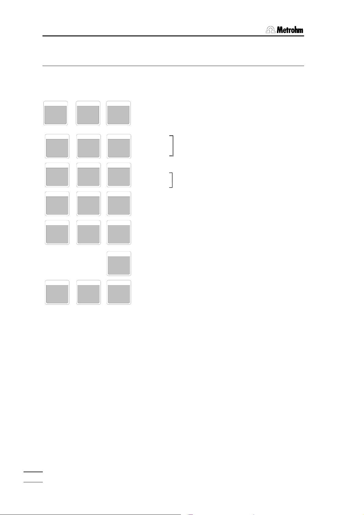
2.1 Keypad
RATE VOLUME EXP
BLANK
7
FACTOR
8
UNIT
4
STORE
5
1
2
0
.
FILL
GO CLEAR
6.2149.000
SMPL
9
RECALL
6
3
MODE
–
ENTER
RATE Expelling and filling rate in all modes.
VOLUME Different volumes depending on selected
mode.
EXP Exponent.
BLANK
FACTOR Calculation parameters in mode DOS.
SMPL
UNIT Unit in modes DOS and CNT
STORE Management of user memory:
RECALL Storing, loading of modes.
MODE Selection of mode.
ENTER Confirmation of entries.
FILL Filling and emergency stop key.
CLEAR Resetting of the volume display to 0 with
Dosimat in stand-by position.
GO Start mode. With mode DOS, dosing
goes on as long as <GO> is pressed.
The keys <FILL>, <CLEAR>, <GO> are identical
with the corresponding keys on Dosimat.
765 Dosimat
4
Page 9
2.1 Keypad
Rules for data input:
• On entering a negative number, key in minus sign first; <-> is not a "change of sign"
key!
• Changeover between first functions (blank, factor etc.) and digits is done
automatically.
• Terminate parameter entries with <ENTER>.
• Some keys are organized as inquiry drums, i.e. pressing these keys several times, dis-
play shows new inquiries. A new value is stored or a new feature is selected with
<ENTER>. The program then returns to the initial state, the inquiry drum is left. Entering an inquiry drum, that inquiry, where the drum has been left last time, is displayed
first.
• The Dosimat works with a resolution of 10'000 pulses per burette cylinder volume.
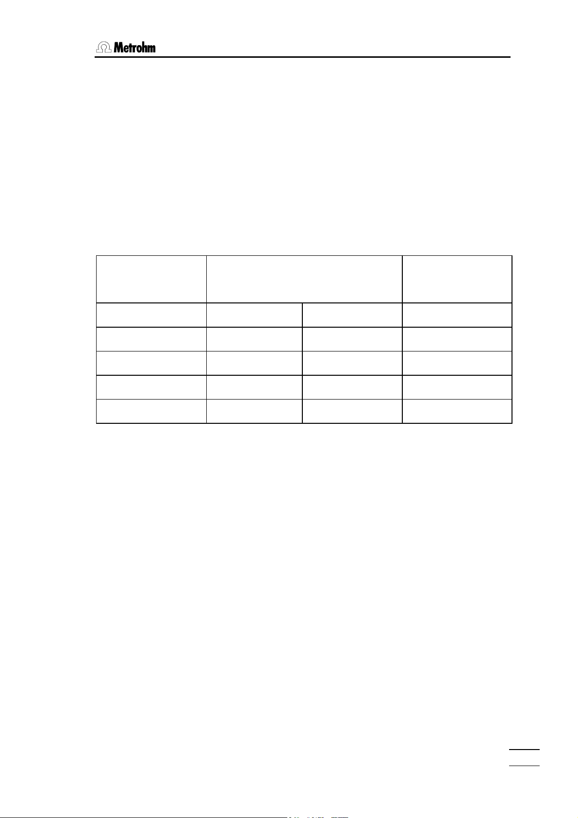
Exchange unit
Resolution of display
Volume/mL Rate mL/min
Smallest increment
V
1 mL .001 .001 0.1 µL
5 mL .001 .005 0.5 µL
10 mL .001 .010 1 µL
20 mL .002 .020 2 µL
50 mL .005 .050 5 µL
If a volume value is entered which can not be dosed exactly with the exchange unit on
the Dosimat, the value is rounded off to the next possible one and stored accordingly.
The smallest possible increments for 1 and 5 mL cylinders are not displayed. However,
they are dosed and the display is rounded.
• Key <CLEAR> sets parameters to "OFF".
765 Dosimat
5
Page 10

2.2. Modes
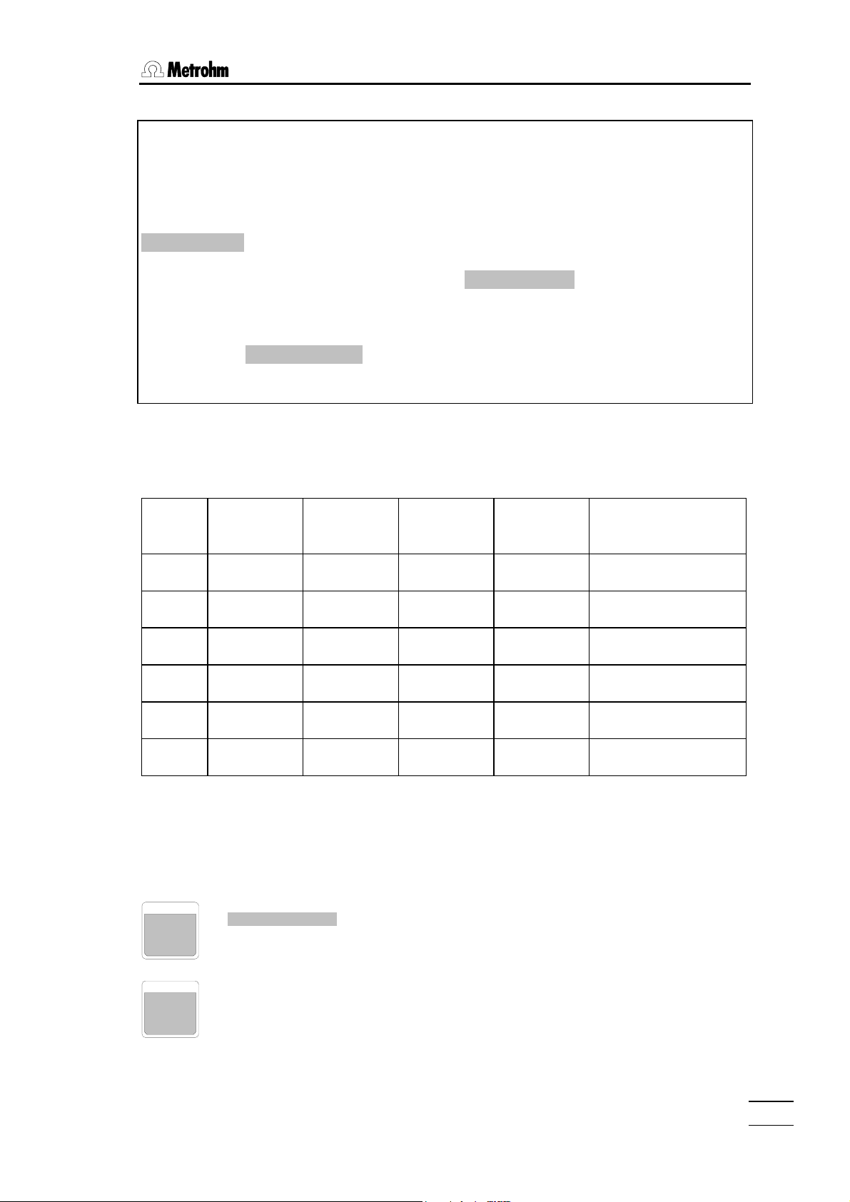
2.1.1 Key <RATE>
The inquiries of this key are identical for all modes.
Expelling and filling rate
RATE
↑ ml/min
↓ ml/min
This key is accessible live (except in mode DOS), i.e. rate can be
changed during a running function .
Expelling rate
Range for digital setting depending on volume of exchange unit:
1 mL 0.001 3.00 mL/min
5 mL 0.005 15.0 mL/min
10 mL 0.010 30.0 mL/min
20 mL 0.020 60.0 mL/min
50 mL 0.050 150.0 mL/min
Key <CLEAR> sets "OFF", i.e.. the rate can be controlled
analogically by means of potentiometer at the Dosimat 765.
If the preset rate is too high to be dosed with the exchange unit
presently mounted, the rate is set automatically to its maximum.
Filling or aspirating rate
The data input rules are the same as for the expelling rate.
The filling rate is set to maximum on changing the exchange unit (e.g.
always after no exch. unit! is displayed!).
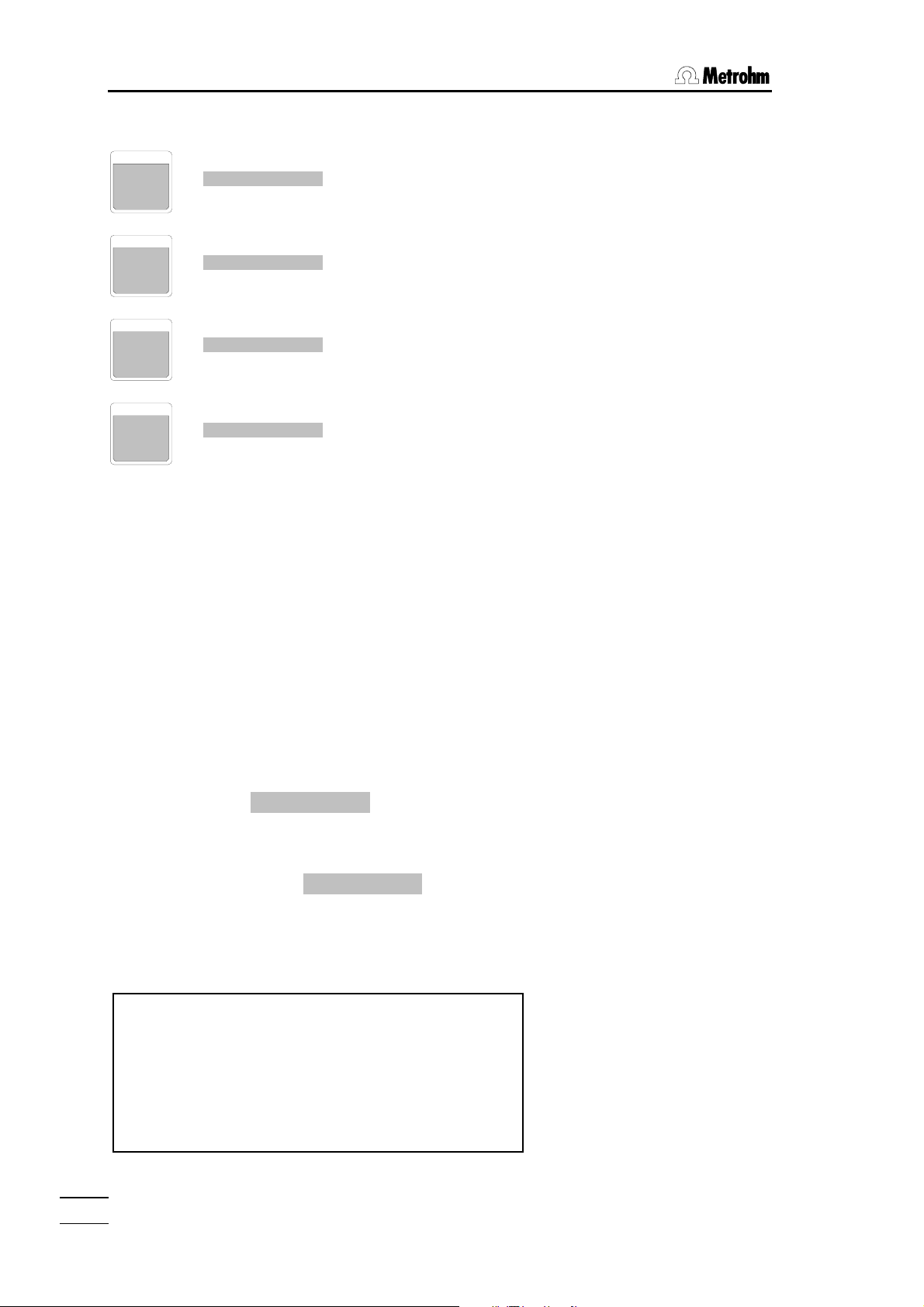
2.2 Modes
MODE
DOS: DOSing
DIS R: DISpensing, Repetitive
DIS C: DISpensing, Cumulative
PIP: PIPetting
DIL: DILuting
CNT D: CoNTent Dispenser
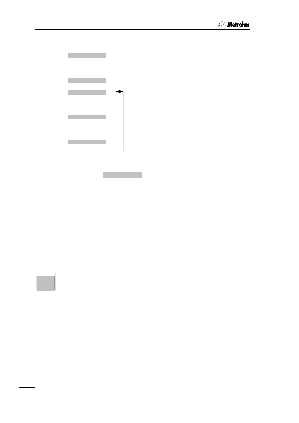
The modes are selected by the inquiry drum <MODE> and
confirmed with <ENTER>.
Dosimat is dosing as long as <GO> is pressed. Result calculation
can be activated.
Dosimat is dosing a stored dispensing volume if <GO> is pressed,
the burette cylinder is refilled and display reset to 0.000 mL.
Dosimat is dosing a stored dispensing volume if <GO> is pressed,
the dispensed volume (V-DIS) remains displayed.
Aspirating and subsequent expelling of a stored pipetting volume.
Aspirating a stored pipetting volume and subsequent expelling of the
pipetting and diluting volume.
Preparation of solutions with preselected content.
765 Dosimat
6
Page 11
2.2 Modes
Example:
Selection of mode "DIS C", cumulative dispensing.
Press <MODE>.
Display shows that mode which has been selected last with key <MODE>, e.g.
DOS .
Press <MODE> repeatedly until display shows DIS C .
Load mode "DIS C" into working memory with <ENTER>.
Display shows DIS C 0.000 ml.
Mode "DIS C" is ready to work, the piston is in zero position.
All modes which are loaded into the working memory by key <MODE> are equipped
with a set of standard parameters:
Mode V-DIS/V-PIP
mL
V-LIM/V-DIL
mL
↑
Rate
mL/min
Rate ↓
mL/min
Calculation
DOS – OFF OFF max. b=0; f=1; s=1
DIS R 1 – OFF max. –
DIS C 0.1 OFF OFF max. –
PIP 0.1 – OFF OFF –
DIL 0.1 1 OFF OFF –
CNT D – – OFF max. –
2.2.1 Mode DOS, Dosing
Dosimat is dosing as long as <GO> is pressed. Result calculation can be activated.
VOLUME
V-LIM OFF ml
RATE
Security volume:
Dosing is stopped if V-LIM has been reached.
Input range: 0.001...999.999 mL, OFF
Expelling and filling rate, see page 6.
765 Dosimat
7
Page 12
2.2. Modes
Calculation values
BLANK
FACTOR
7
8
SMPL
9
UNIT
4
b = 0. ml
f = 1.
s = 1.
unit
Blank value
Input range: 0...±999.999 mL
Factor
Input range: 0... ±1E33
Sample size
Input range: 0... ±1E33
Input manually or on-line with balance, see page 56
Unit
Input range: ppm, %, g, mg, g/L, mg/L, mol, mol/L, mL, L,
/pc, none
Result calculation
If one of the calculation values (blank, factor, smpl) is not set to its standard value, a
result is calculated on filling of the Dosimat according to formula:
(dosed volume–blank)*factor
Result = ————————————————
smpl
The result is recalculated on each entry of a calculation value (blank, factor, smpl).
Pressing <CLEAR> display shows the dosed volume in mL. To start a new dosing, press
<GO> twice, pressing once resets the volume in display to 0.000 mL.
Printing the result on a printer
If Dosimat is set to send RS 232 on (special settings see page 18), filling the Dosimat or
re-calculation triggers a print command. A continuous number (#), the dosed volume and
the calculated result are printed.
Do set new calculation parameters for the next dosing only after having pressed <GO>
once, i.e. if display shows DOS 0.000 ml.
The continuous number is set to zero on switching on the Dosimat and incremented by 1
on every filling command.
Example of print-out
#01 V = 0.352 ml R = 7.04 ppm
#02 V = 0.440 ml R = 8.8 ppm
#03 V = 0.000 ml
#04 V = 0.364 ml R = 7.28 ppm
#05 V = 0.438 ml R = 8.76 ppm
#06 V = 0.382 ml R = 7.64 ppm
#07 V = 0.370 ml R = 19.61 %
#08 V = 0.372 ml R = 19.72 %
765 Dosimat
8
Page 13

2.2 Modes
2.2.2 Mode DIS R, Repetitive Dispensing
Dosimat is dosing a stored dispensing volume if <GO> is pressed. The burette cylinder
is refilled and display reset to 0.000 mL.
Dispensing volume
Input range: 0.001...999.999 mL
VOLUME
V-DIS 1. ml
RATE
Expelling and filling rate, see page 6.
2.2.3 Mode DIS C, Cumulative Dispensing
Dosimat is dosing a stored dispensing volume if <GO> is pressed, and the dispensed
volume (V–DIS) remains displayed.
Dispensing volume
Input range: 0.001...999.999 mL
Security volume
Dispensing is stopped, if V-LIM has been reached.
Input range: 0.001...999.999 mL, OFF
Expelling and filling rate, see page 6.
VOLUME
RATE
V-DIS 0.1 ml
V-LIM OFF ml
Tandem Dosing
Mode DIS C is suitable for continuous dosing with 2 Dosimats, see page 57.
765 Dosimat
9
Page 14

2.2. Modes
2.2.4 Mode PIP, Pipetting
Aspirating and subsequent expelling of a stored pipetting volume.
VOLUME
V-PIP 0.1 ml
RATE
If mode PIP is loaded, the display shows PIP * 0.000 ml.
The sign * in the display means that mode "PIP" is not yet ready to be used. With a first
<GO>, a preparation step is carried out which is marked in the display with
PIP prep. . This preparation step includes the formation of an air bubble which
serves to separate the transfer solution of the exchange unit from the sample.
Then display shows PIP 1 0.100 ml, i.e. the Dosimat is ready to aspirate the pipetting
volume (0.1 mL). With <GO> the pipetting volume is aspirated and display shows
PIP 2 0.100 ml which means that the Dosimat is ready to expel the pipetting volume.
With the next <GO>, the volume is expelled and the Dosimat is then ready to aspirate
the next pipetting volume without any preparation step.
If the pipetting volume is changed, a new preparation step is always carried out.
Sequence of PIP
PIP * 0.000 ml
↓
<GO>
↓
PIP prep.
↓
PIP 1 0.100 ml
↓
<GO>
↓
PIP 2 0.100 ml
↓
<GO>
↓
Note
Pipetting volume
Input range depends on the volume of the exchange unit:
1 mL 0.001... 0.900 mL
5 mL 0.001... 4.900 mL
10 mL 0.001... 9.800 mL
20 mL 0.002... 19.700 mL
50 mL 0.005... 49.500 mL
Note: The liquid of the exchange unit is mixed with the
pipetted liquid if it is aspirated into the burette cylinder!
The aspiration tube must contain V-PIP!
Expelling and filling rate see page 6.
Standard mode PIP.
Preparation step: Hold burette tip free at working
height.
Ready to aspirate the pipetting volume: Immerse
burette tip.
Ready to expel the pipetting volume: Hold
burette tip for pipetting.
765 Dosimat
10
Page 15

2.2 Modes
• A new air bubble is built with every preparation step ("prep.") e.g. its volume increases.
If you wish to keep the volume of the air bubble expel it in mode DOS before changing
V-PIP.
• For best pipetting results we recommend exchange units with volumes ≤ 20 mL and
pipetting equipment 6.5611.000.
• The aspirating and expelling rates should not be higher than 20 mL/min.
• Hold tubing tip in an angle of app. 45° to the vessel wall during pipetting. Just the
same as you do with glass pipettes!
• The vessel, containing the liquid you want to pipette should stand on the same level as
the vessel into which you are going to expel the liquid in order to ascertain app. the
same level of the pipetting tubing during work.
2.2.5 Mode DIL, Diluting
Aspirating a stored pipetting volume and subsequent expelling of the pipetting and diluting volume.
Pipetting volume
Input range depends on the volume of the exchange unit:
1 mL 0.001... 0.900 mL
5 mL 0.001... 4.900 mL
10 mL 0.001... 9.800 mL
20 mL 0.002... 19.700 mL
50 mL 0.005... 49.500 mL
Diluting volume
Input range: 0.001...999.999 mL
Note: The diluting liquid is unintentionally mixed with the
pipetted liquid if it is aspirated into the burette cylinder!
The aspiration tube must contain V-PIP!
Expelling and filling rate see page 6.
VOLUME
RATE
V-PIP 0.1 ml
V-DIL 1. ml
If mode DIL is loaded, the display shows DIL * 0.000 ml.
The sign * in the display tells you that mode DIL is not ready to be used. With <GO> a
preparation step is carried out during which V-PIP is expelled into the bottle of the
exchange unit and an air bubble is built to separate the solution of the exchange unit from
the sample.
Then the Dosimat is ready to aspirate the pipetting volume (0.1 mL) which is displayed by
DIL 1 0.100 ml and carried out after pressing <GO>.
Then DIL 2 1.100 ml is displayed which means that the Dosimat is ready to expel the
pipetting and the diluting volume (0.1 mL + 1 mL = 1.1 mL). This is executed after
<GO>. The preparation step is now carried out automatically and the Dosimat is ready to
aspirate the next pipetting volume.
765 Dosimat
11
Page 16
2.2. Modes
Sequence of DIL
DIL * 0.000 ml
↓
<GO>
↓
DIL prep.
↓
DIL 1 0.100 ml
↓
<GO>
↓
DIL 2 1.100 ml
↓
<GO>
↓
DIL prep.
↓
Standard mode DIL.
Preparation step: Hold burette tip free at working
height.
Ready to aspirate the pipetting volume: Immerse
burette tip.
Ready to expel the pipetting and diluting volume:
Hold burette tip for pipetting.
Notes
• If you wish to change V-PIP, it is best to change it during filling in the preparation step,
i.e. when display shows DIL ↓ prep..
• If V-PIP is changed at another time, a new preparation step is carried out, which
changes the volume of the air bubble. The first dilution after such a change could be
erroneous and should be discarded. Another possibility is to expel the air bubble in
mode DOS and to start Mode DIL from the beginning. V-DIL can be changed at any
time without a new preparation step.
2.2.6 Mode CNT D, Content Dispenser
Mode CNT D is used to prepare solutions with a particular content. Doing this, the substance must not be weighed-out to a particular value in order to obtain the preselected
content but the 765 Dosimat dispenses the amount of solvent calculated correspondingly.
RATE
Expelling and filling rate see page 6.
765 Dosimat
12
Page 17
2.2 Modes
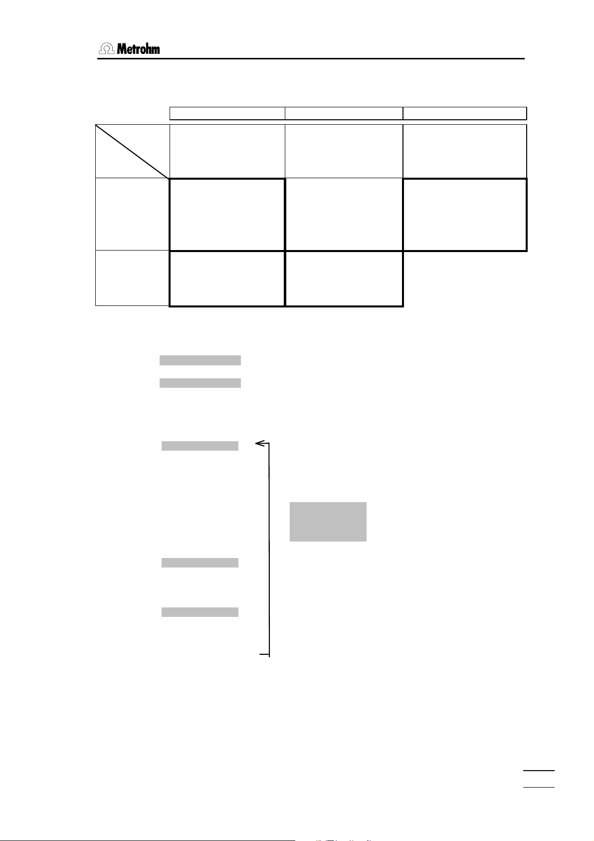
Content entries which can be implemented in the CNT D mode are summarized below
and designated with a bold frame
Reference quantity
(denominator)
Specified
quantity
(numerator)
Amount of
substance
/ mol
n
i
Mass
/ kg
m
i
Concentration Fraction Molality
Volume
of the solution
V / L
Amount of substance
concentration c
c
= ni/V
Units: mol/L, mmol/L
Example: c(NaOH)=0.1 mol/L
Outdated: molarity, molar
Mass concentration ρ
Units: g/L, mg/L
Example: ρ(Pb
Outdated: mg%
i
= mi/V
ρ
i
2+
)= 1 g/L
Amount of substance
fraction x
Unit: 1
Example: x(Au)=0.005
Outdated: mole fraction, mole
Mass fraction w
Units: %, ppm; 1
Example: w(H
Outdated: weight percent
Sum
of the components j
xi = ni/Σnj
percent
= mi/Σmj
w
i
O)= 5%
2
Mass
of the solvent
/ kg
m
k
Molality b
= ni//mk
b
Unit: mol/kg, mmol/kg
Example: b(KOH, in EtOH) = 1
i
mol/kg
Sequence of CNT D
CNT D 0.000 ml
↓
unit %
↓
↓
<ENTER>
↓
cnt 1 %
↓
Input <ENTER>
↓
↓
↓
↓
↓
↓
s 1 g
↓
Input <ENTER>
Standard mode CNT D. Display changes
automatically after preparation.
Choose unit by pressing key <UNIT>.
The volume is calculated according to the
chosen unit.
Input of the desired numerical value for the
content.
Depending on the unit selected the following
auxiliary variables are inquired during the first
run:
M 1 g/mol Molar mass of the substance
dens. 1 g/ml Density of the solvent
f 1.00000 Factor for volume contraction
Input of the weight manually or via a balance,
see page 56.
↓
add V XXX.XXX ml
↓ ↓
<GO> <CLEAR>
↓
dosing V
The calculated volume is displayed and expelled
with <GO>.
With <CLEAR> the values for "cnt" and/or "s" can
be changed. This gives an idea of the
approximate weighing.
Pressing <MODE>, the mode can be changed.
765 Dosimat
13
Page 18
2.2. Modes
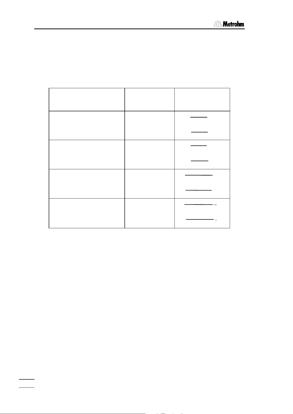
The formulae for calculation of the volume to be dispensed "add V" are shown in the
following table, with
cnt content in the selected unit
M molar mass of substance to be weighed out
f factor
dens density of the solvent
s weight of substance
Unit Formula for
add V =
Amount-of-substance
concentration
mol/L
mmol/L
f·s·10
f·s·10
cnt·M
6
3
cnt·M
3
f·s·10
Mass concentration
g/L
mg/L
cnt
f·s·10
6
cnt
2
f·s(10
Mass fraction
%
ppm
-cnt)
cnt·dens
6
f·s(10
-cnt)
cnt dens
Molality
mol/kg
mmol/kg
s·10
cnt·M·dens
s·10
3
6
cnt·M·dens
Application of factor f
Factor f for ionic standards
With ionic standards, the mass fraction of a single ion A is usually specified. On the other
hand, the solution is prepared from A
Pb(NO
. The factor f is calculated from the formula:
3)2
, e.g. a standard of 10 ppm Pb2+ prepared from
nBm
n*M(A) m*M(B)
f = ———— or f = ————
M(A
) M(AnBm)
nBm
M(A): molar mass of ion A
M(B): molar mass of ion B
M(A
): molar mass of substance AnBm
nBm
765 Dosimat
14
Page 19
2.2 Modes
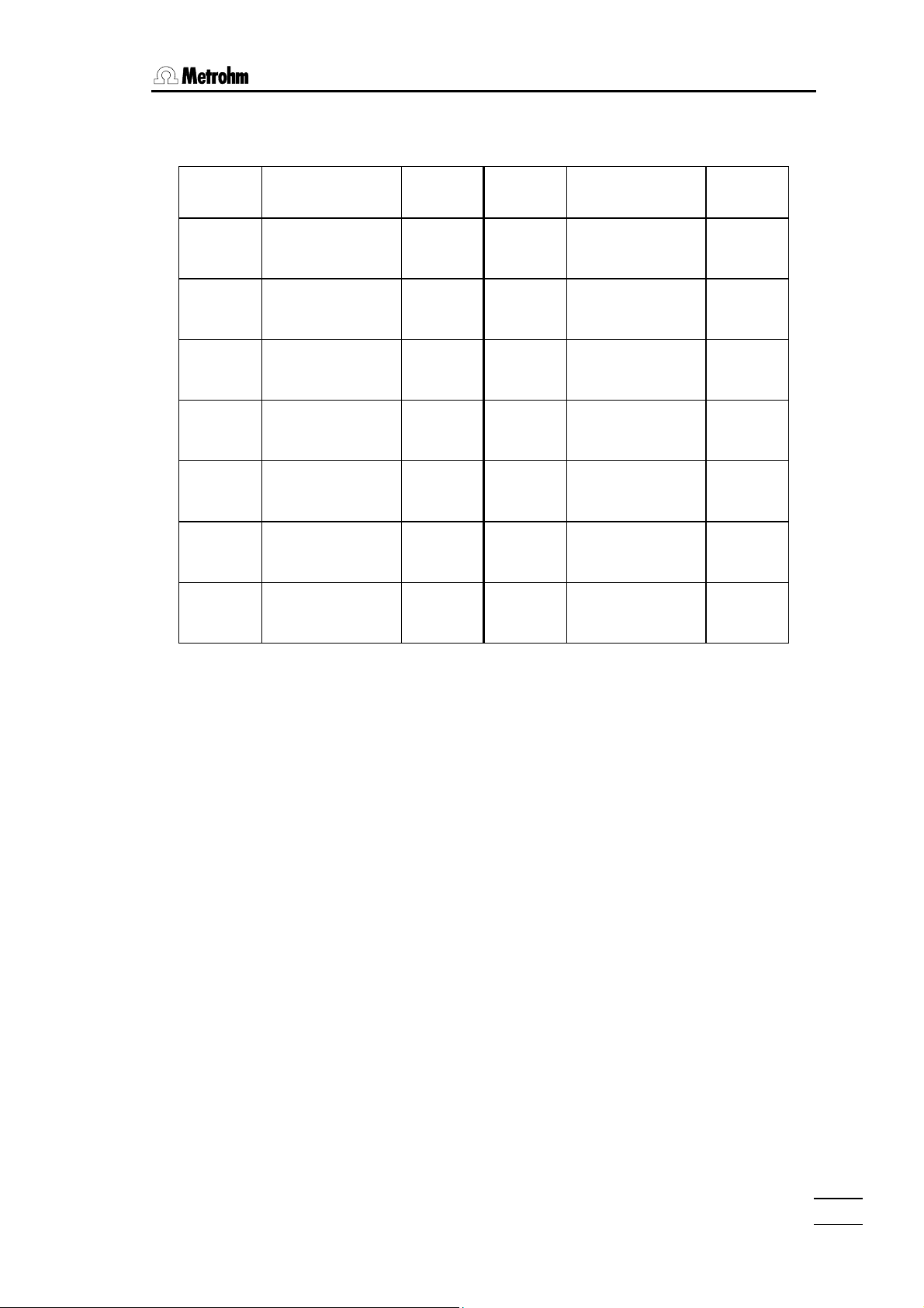
The following table shows factors for the most common ionic standards:
Cation Standard
prepared from:
Na+ NaCl
Factor f Anion Standard
prepared from:
0.39339
-
F
NaF 0.45245
Factor f
NaNO
3
K+ KCl
KNO
3
Ca2+ CaCl2 0.36111 Br- NaBr·2H2O
Ba2+ BaCl2·2H2O
Ba(NO
3)2
Cu2+ Cu(ClO4)2
Cu(NO
·6H2O
3)2
Pb2+ Pb(ClO4)2·3H2O
Pb(NO
3)2
PO
0.27050
0.52441
0.38670
0.56222
0.52550
0.24214
0.21494
0.45028
0.62557
-
Cl
NaCl
KCl
0.60666
0.47550
0.57514
KBr
-
I
KI 0.76444
2-
SO
K
4
-
NO
NaNO3
3
3-
Na2HPO4·12H2O
4
Na
3PO4
0.55087
2SO4
KNO
3
·12H2O
0.67141
0.72950
0.61319
0.26519
0.24985
The factor f as correction for substances with admixtures
e.g. water of crystallization, impurities, moisture.
The factor f as correction for the volume contraction
For the amount-of-substance concentration c (units mol/L and mmol/L) and the mass
concentration ρ (units g/L and mg/L), the concentration is referred to the volume of the
solution.
c
= ni/V resp. ρi= mi/V
i
where n
m
amount of substance i
i
mass of substance i
i
V volume of the solution
765 Dosimat
15
Page 20
2.2. Modes
Since the volume of the solvent V0 is dispensed in the operational method of the CNT D
mode, higher concentrations require a correction factor which takes the difference
between V
and V (volume of the solution) into consideration:
0
V
0
f = —–
V
This factor can be determined with the Dosimat in the DOS mode:
A solution of the desired concentration is prepared in the conventional manner in a
volumetric flask by dispensing the solvent with the aid of the Dosimat up to the mark of
the flask (V
). If the volume V of the volumetric flask is inputted in the calculation
0
parameter "s", the factor f is calculated directly by the Dosimat and appears on the
display.
The factor f determined in this manner holds for the appropriate substance/solvent pair in
the measured concentration range with the possibility of linear extrapolations up to
concentrations of ca. 1 mol/L.
Several correction factors are shown in the following table:
Concentration c
0.05
mol/L
0.1 mol/L 1 mol/L
Substance/solvent
Potassium hydrogen
0.999 0.998 0.982
phthalate/water
Na2EDTA·2H2O/water 0.991 0.981 -
NaCl/water 0.999 0.998 0.982
KNO3/water 0.998 0.997 0.960
CuSO45H2O/water 0.995 0.992 0.904
765 Dosimat
16
Page 21

2.3 User memory
2.3 User memory
Up to 10 modes, complete with their user selected specific parameters, can be stored in
the user memory.
The relation of the different memories is shown in the following table:
Fixed memory
contains:
modes with standard
parameters:
DOS
DIS R
DIS C
PIP
DIL
CNT D
Working memory
contains:
1 mode; parameters can
be modified
<MODE> <STORE>
<RECALL>
Management of user memory
STORE
STORE
5
RECALL
6 5
<STORE><X><ENTER>
Storing a mode at address X
(X=0,1,...9)
<RECALL><X><ENTER>
Loading a mode from the user memory into the working
memory.
Ex factory, the standard modes are stored in the user
memory.
User memory
contains:
up to 10 user modes
765 Dosimat
17
Page 22

2.4. Special settings
2.4 Special settings
Special settings can be executed by pressing keys <0> and <—> simultaneously. The
display shows Sys. Soft-Reset . Press key <0> and keep it pressed until special key 0..6
appears in the display.
Press key 1...6. Pressing key <CLEAR> once, leads back to the blinking display
special key 0..6 and pressing key <CLEAR> again leads to the corresponding mode in
the working memory.
Pressing key <GO>, the next inquiry is displayed, with <ENTER> the setting is stored.
Key Display Explanation
< 0 > 5.765.0010 Display of program number
< 1 > baud rate 9.6 K Setting of baud-rate: 110, 150, 300, 600, 1.2K, 2.4K,
4.8K, 9.6K, 19.2K: Press <GO> until the right
number is displayed and store with <ENTER>.
Several quantities are set to a fixed value: data bit
= 7, parity = even, stop bit = 1.
< 2 > #V(B)/1000 mV 1 Number of burette volumes per ∆U = 1000 mV at
the analogue output: 1,2...10 V(B). Press <GO>
until the right number is displayed and store with
<ENTER>.
< 3 > auto fill on Automatical refilling in mode DOS if more than one
burette volume has been expelled: on = yes; off =
no. Press <GO> until the right answer is displayed
and store with <ENTER>.
< 4 > send RS232 off Data transfer in mode DOS: on = yes, off = no.
Press <GO> until the right answer is displayed and
store with <ENTER>.
< 5 > balance Mettler Choice of balance to be connected: Mettler, Sartori
(=Sartorius). Press <GO> until the right balance
is displayed and store with <ENTER>. For detailed
information about the connection of a balance see
page 56.
< 6 > RS232 HSHK full Choice of handshakes for data transfer to RS232:
full, none.
"full" is used for connections with Metrohm
instruments.
"none" can be used e.g. for data transfer via a
Windows terminal.
See also page 45.
765 Dosimat
18
Page 23

3.1 Special messages and error messages
3 Error messages, troubleshooting
blinking value The value keyed in is out of the input range.
3.1 Special messages and error messages
cylinder empty! The Dosimat is set to "auto fill off" and one burette volume has
been expelled in mode DOS.
Exit: <FILL>
error 1 Check sum error in PROM.
Remedy: Call Metrohm-Service
error 2 RAM-check: Error in on-chip-RAM.
Remedy: Call Metrohm-Service
error 3 RAM-check: Error in off-chip-RAM.
Remedy: Call Metrohm-Service
error 4 RAM-check: Error in on- and off-Chip-RAM.
Remedy: Call Metrohm-Service
error 5 Check sum error in off-chip-RAM.
Remedy: RAM has to be re-initialized: Switch Dosimat off.
Press <FILL> during switching it on again. Display shows
"RAM init.". Press <GO> . Display shows "RAM init. passed".
<CLEAR> leads to basic program.
Note: Stored user modes will be cleared on re-initializing of the
RAM and standard mode DOS is loaded into the working
memory.
INF In mode DOS, a result has been calculated with s=0 or the
calculated result is larger than the range of numbers which can
be displayed (1 E+39).
Exit: <CLEAR>
NaN (Not a number). In mode DOS, a result has been calculated
with s=0 and f=0.
Exit: <CLEAR>
no exch. unit! Exchange unit is not (properly) mounted.
Exit: Mount exchange unit properly.
Note: The filling rate is set to maximum.
V> XXXX ml In mode CNT D the volume to be dosed is >999.999 mL.
Exit: <CLEAR> and enter new weight.
V< XXXX ml In mode CNT D the volume to be dosed is smaller than the
smallest possible increment which can be dosed with the exchange unit mounted.
Exit: <CLEAR> and enter new weight.
765 Dosimat
19
Page 24

3.1. Special messages and error messages
volume <resol.! The volume to be expelled is smaller than the resolution of the
burette with the exchange unit mounted on the Dosimat.
Exit: Change volume to a value which can be expelled with
the exchange unit mounted on the Dosimat
or
mount an exchange unit where the volume can be
expelled.
V-LIM reached! Security volume is reached.
Exit: <FILL>.
V-PIP > V(B) The stored pipetting volume is higher than the burette volume
of the exchange unit mounted on the Dosimat.
Exit: Change volume to a value which can be expelled with
the exchange unit mounted on the Dosimat
or
mount an exchange unit where the volume can be
expelled.
765 Dosimat
20
Page 25

3.2 Diagnosis
3.2 Diagnosis
3.2.1 General
The 765 Dosimat is a very precise and dependable feeding instrument.
Thanks to its rugged construction, it is highly unlikely that external mechanical or electrical influences will have any adverse effect on its functions.
Although a fault in the instrument can not be excluded with certainty, the
possibility is greater that malfunctions are caused by wrong operation or
handling, through improper connections and the operation with third-party
devices.
Whatever the case, it is always advisable to localise the fault with the diagnostic tests, which can be performed quickly and simply. The customer
need call Metrohm service only when the instrument really has a fault. Further, he can use the results of the specific diagnostic function to provide the
service engineer with much more precise information.
In the case of inquiries, always quote the serial number on model plate
(see page 3), the program version (see page 18) and if applicable the error
message.
Procedure
The diagnostic menu listed in section 3.2.2 shows all components for which
detailed instructions (diagnostic steps) are available for checking the functionality.
In the case of a possible malfunction, we advise you to perform either the
corresponding diagnostic step or all diagnostic steps as a routine check on
the instrument.
The reactions of the Dosimat to the instructions must be compared with the
descriptions in the diagnostic step. If the Dosimat do not show the expected reaction ("No" case), the appropriate diagnostic step must be repeated to exclude operating errors. However, it is highly probable that repeated wrong reactions indicate a malfunction.
Equipment required:
3.496.0070 Dummy-exchange unit (or exchange units if possible with different cylinder
6.2107.000 Push-button cable or ordinary test lead with 4 mm banana plugs
6.2149.000 Keyboard
3.496.8360 Test plug
-.---.---- Stop watch or watch with second hand.
-.---.---- Voltmeter (perhaps a calibrated recorder)
volumes).
765 Dosimat
21
Page 26

3.2. Diagnosis
3.2.2 Summary
3.2.4 Diagnosis of cylinder code..............................................23
3.2.5 Diagnosis of key board....................................................23
3.2.6 Diagnosis of display ........................................................23
3.2.7 Diagnosis analog output .................................................24
3.2.8 Diagnosis of digital timer .................................................25
3.2.9 Diagnosis of analog timer................................................26
3.2.10 Diagnosis of external inputs, outputs..............................26
3.2.11 RAM-test ..........................................................................27
3.2.12 Diagnosis of spindle zero and cock changeover............27
3.2.13 Diagnosis of spindle drive ...............................................27
3.2.3 Prepare instruments for diagnostic tests
1.
Power off.
2.
Remove exchange unit.
3.
Disconnect all cables at rear, except mains cable and keyboard.
4.
Power on and simultaneously press key <9> and keep pressed until
5.
diagn. key 0...9
The individual inquiries of the several diagnostic steps are accessed using the key
<0> ... <9>, exit is with the <CLEAR> key.
diagn. key 0...9
║
║
╠══ < 0 >
║
╠══ < 1 >
║
╠══ < 2 >
║
╠══ < 3 >
║
╠══ < 4 >
║
╠══ < 5 >
║
╠══ < 6 >
║
╠══ < 7 >
║
╠══ < 8 >
║
╚══ < 9 >
cylinder code
keys test
display test
analog output
timer dig. test
timer ana. test
extern in/output
spind. mot. cal.
RAM TEST
RAM init.
Instrument adjustment
1)
1)
This diagnostic step is reserved for the service engineer and therefore will not be described within this document.
765 Dosimat
22
Page 27

3.2 Diagnosis
3.2.4 Diagnosis of cylinder code
1.
Prepare instrument for diagnostic test (see chap. 3.2.3).
2.
<0>
3.
4.
5.
6.
cylinder code
<GO>
no exch. unit!
Insert (dummy) exchange unit.
code: xx ml
Check whether the displayed ml-Code (xx ml) corresponds to the exchange unit.
Various exchange units can be inserted to verify their ml-code.
If an exchange unit is coded incorrectly or if the code switches are inoperative, the display shows: E 90: ..
no code!
<CLEAR>
diagn. Key 0...9
3.2.5 Diagnosis of key board
1.
Prepare instrument for diagnostic test (see chap. 3.2.3).
2.
<1>
keys test }
3.
<GO>
4.
5.
key: rate
The display requests to press the key <RATE> on the keyboard 6.2149.000.
<RATE>, <7>, <4>, <1> etc.
If the correct key was pressed and the test was positive the name of the next key to be pressed will be displayed.
Display E 10: and on the right-hand side the name of an other key indicates a fault in the keyboard matrix, or
the wrong key was pressed.
A fault indication may be cancelled by pressing <CLEAR>. “breaking off ?“ is then displayed, asking you
whether you want to stop the test or not.
- To stop press <CLEAR>.
- To continue press <GO> until the display shows “keys test end“
After pressing the last key (GO), the following appears:
keys o.k.
<CLEAR>
diagn. key 0...9
3.2.6 Diagnosis of display
765 Dosimat
1.
Prepare instrument for diagnostic test (see chap. 3.2.3).
23
Page 28

3.2. Diagnosis
2.
<2>
3.
4.
display test
<GO>
Characters are generated for an optical check of the display:
1. The display is written to from left to right with the character
2. Repeatedly the display is written to with the characters
3. In quick succession the display is written to with the capital letters from the alphabet.
4. The display is written to with the character set (see Fig. 1) as continuous moving display.
The test sequence can be held by pressing key <5> and restarted.
The continuous moving display is quit by pressing the keys <5> and <CLEAR>.
DP, keys test for 1.5 s
key: FILL }
The display requests to press the key <FILL> on the front of the Dosimat.
<FILL>, <CLEAR>, <GO>
If the correct key was pressed and the test was positive the name of the next key to be pressed will be displayed.
Display E 10: and on the right-hand side the name of an other key indicates a fault in the keyboard matrix, or
the wrong key was pressed.
A fault indication may be cancelled by pressing <CLEAR>. “breaking off ?“ is then displayed, asking you
whether you want to stop the test or not.
- To stop press <CLEAR>.
- To continue press <GO> until the display shows “keys test end“
After pressing the last key (GO), the following appears:
keys o.k.
.
and .
5.
<CLEAR>
diagn. key 0...9
Fig. 1
3.2.7 Diagnosis analog output
To carry out this diagnosis step the optional analog output has to be fitted in the Dosimat (fitted as a standard with versions 2.765.0020, 2.765.0040)
765 Dosimat
24
Page 29

3.2 Diagnosis
1.
Prepare instrument for diagnostic test (see chap. 3.2.3).
2.
Connect voltmeter, DVM or recorder by means of cable 3.980.3170 to location A
(do not switch off the unit).
3.
Plug A Pin 21 (0...+1 V)
Plug A Pin 11 (ground)
<3>
4.
<GO>
5.
<GO>
6.
<GO>
7.
<2>, <GO>
analog output
V-out = 0.000 V
Measuring instrument reads 0 V (tolerance ±6 mV). Take also into account the tolerance of the measuring
instrument!
V-out = 1.000 V
Measuring instrument reads +1.000 V (tolerance ±6 mV + tolerance of point 4.)
V-ramp 1...2
In this test sequence the Dosimat produces at the analog output a triangle voltage. Two different rising or falling times can be selected:
1: rising or falling time = 48 ms (reserved for the service engineer)
2: rising or falling time = 40 s
V-ramp = 40s ↑/↓
U
[V]
out
1
0 t [s]
Within the first 40 s the voltage rises linear.
Within the second 40 s the voltage falls linear.
When terminated the display shows:
8.
9.
V-ramp = 1...2
<CLEAR>
diagn. key 0...9
Remove cable and measuring instrument.
40
3.2.8 Diagnosis of digital timer
The digital timer is that part of the electronic circuit in the dosimat which is responsable
for the digital spindle speed rate.
765 Dosimat
80
25
Page 30

3.2. Diagnosis
1.
Prepare instrument for diagnostic test (see chap. 3.2.3).
2.
<4>
3.
4.
timer dig. test
<GO>
timer dig.
The frequency of the digital timer is measured during 1.5 s. If no fault is found, the following appears:
timer dig. o.k.
<CLEAR>
diagn. key 0...9
3.2.9 Diagnosis of analog timer
The analog timer is that part of the electronic circuit in the dosimat which is responsable
for the analog spindle speed rate (adjustable with knob 'dV/dt').
1.
Prepare instrument for diagnostic test (see chap. 3.2.3).
2.
Turn knob 'dV/dt' fully to the right.
3.
<5>
4.
timer ana. test
<GO>
5.
timer ana.
The frequency of the analog timer is measured during 1.5 s. If no fault is found, the following appears:
timer ana. o.k.
<CLEAR>
diagn. key 0...9
3.2.10 Diagnosis of external inputs, outputs
This test is necessary only if the 765 Dosimat is interconnected with other instruments via
terminal A. Moreover, this test requires the test plug 3.496.8360 which is a facility for the
repair service. However, it can also be ordered by customers with the above order number.
1.
Prepare instrument for diagnostic test (see chap. 3.2.3).
2.
Without switching off the instrument, insert plug 3.496.8360 into location A. Take
care of the direction of the plug. Red banana plug to red socket 'D'.
3.
<6>
4.
extern in/output
<GO>
The test runs automatically. If no fault is found, the following appears:
ext. in/out o.k.
765 Dosimat
26
Page 31

3.2 Diagnosis
5.
<CLEAR>
6.
diagn. key 0...9
Remove test plug 3.496.8360.
3.2.11 RAM-test
1.
Prepare instrument for diagnostic test (see chap. 3.2.3).
2.
<8>
3.
4.
RAM test
<GO>
The test runs automatically. If no fault is found, the following appears:
RAM TEST passed
<CLEAR>
diagn. key 0...9
3.2.12 Diagnosis of spindle zero and cock changeover
1.
Power off.
2.
Insert exchange unit.
3.
Power on.
4.
5.
Dosimat fills.
Remove exchange unit.
To check the spindle zero.
The spindle must be 0.2 - 0.6 mm below the edge of the mounting plate (see Fig. 2).
The link piece of the cock coupling must be parallel to the side walls of the Dosimat (see Fig. 3).
0.2 - 0.6 mm
Fig. 2 Fig. 3
3.2.13 Diagnosis of spindle drive
1.
Insert exchange unit and put the burette tip into a collecting receptacle.
2.
Connect push-button cable 6.2107.000 (if available).
765 Dosimat
27
Page 32

3.2. Diagnosis
3.
Power off and wait for 5 s.
4.
Power on and simultaneously press key <0> and keep pressed until:
5.
6.
7.
8.
9.
10.
special key 0..6
<3>
auto fill ???
└─┬─┘
check whether display reads 'on' or 'off' (make note!)
Press <GO> if auto fill 'on' otherwise go on with item 7.
auto fill off
<ENTER>, <CLEAR>
The dotted pattern is displayed, afterwards the display changes to the mode used last before starting the diagnosis.
Dosimat fills.
Actuate <MODE> several times until the display shows:
DOS
< ENTER >
DOS 0.000 ml
<RATE>
11.
12.
13.
14.
15.
↑ OFF ml/min
< RATE >
↓ xx ml/min
xx : (depending on exchange unit code)
<CLEAR>
↓ OFF ml/min
< ENTER >
DOS 0.000 ml
Knob 'dV/dt' fully to the right.
Press feed button 6.2107.000 (if not available, <GO>) all the time until the piston
rod reaches the top position and simultaneously measure the time from start to
stop.
16.
cylinder empty!
Spindle remains at top position.
The running time of the spindle is 18 ... 22 s.
Measure the spindle height [can be performed only if dummy exchange unit
3.496.0070 is fitted, or the exchange unit removed and the locking switch (in the
right-hand hole) carefully actuated by means of a screw driver].
765 Dosimat
28
Page 33

3.2 Diagnosis
17.
The spindle moves 80 mm with respect to spindle zero.
Instead of the spindle height one can also measure the expelled volume (corresponding to the max. volume
of the exchange unit).
Actuate <FILL> and simultaneously take the time until the dosimat is in 'ready'
position again.
18.
19.
20.
21.
22.
Filling time: one cock cycle 1 s
filling 18 ... 20 s
General rules:
Spindle and cock must move in regular speed (observe sound!)
In the filling position the cock coupling must turn the lever of the exchange unit blamelessly to the left stop
(almost without play and without jamming).
Knob 'dV/dt' fully to the left.
<MODE>: select DIS R.
<ENTER>
DIS R 0.000 ml
<VOLUME>
V-DIS 1. ml
Depending on the exchange unit used, enter the volume as below:
1 ml: 0.02 ml
5 ml: 0.1 ml
10 ml: 0.2 ml
20 ml: 0.4 ml
50 ml: 1 ml
23.
<ENTER>
24.
<GO> (depress briefly) and with a stop watch take the time until the cock starts
turning.
25.
The time must be 14 ... 24 s.
Reset the parameter if under 5. the reading was auto fill = on .
765 Dosimat
29
Page 34

3.3. RAM-initialisation
3.3 RAM-initialisation
In rare cases, it is possible that major interference signals such as line spikes and lightning can have an adverse influence on the contents of the data memory. If the contents
of the data memory are undefined, this is indicated after “power on“ with ‘error 5'. The
keyboard is then blocked, no entering is possible until the RAM is initialised again.
1.
Disconnect all cables at rear, except mains cable.
2.
Power off and wait 5 s.
3.
Power on and simultaneously press key <FILL> and keep pressed until
4.
5.
RAM init.
<GO>
RAM init. passed
<CLEAR>
DOS 0.000 ml
Dosimat fills.
The RAM-initialisation deletes the data present in the User-Memory and also those for the special functions
and overwrites them with the standard data below:
The User-Memory is loaded with the standard modes.
Memory 0: Mode DOS
1: DIS R
2: DIS C
3: PIP *
4: DIL *
5: DOS
6: DIS R
7: DIS C
8: PIP *
9: DIL *
The working memory is loaded with the standard mode DOS. The special functions of the dosimat are set to
the following values:
Analog output scale: 1 stroke per 1000 mV
RS 232 sending: off
Baudrate: 9600 Baud
auto. filling: on
765 Dosimat
30
Page 35

3.4 Releasing a locked spindle
3.4 Releasing a locked spindle
with inserted Exchange Unit
The burette drive may very occasionally jam at the top or bottom end of the cylinder. If
jamming occurs at the top or when the drive is out of function, the Exchange Unit can no
longer removed. In this case, it is necessary to proceed as follows:
2 screws (M4 countersunk)
Fig. 4
1.
Disconnect instrument from power supply!
2 screws (M3 fillister head)
knob
edge of bench
2.
Remove control knob.
3.
Place instrument over edge of bench to allow the M3 screws to be removed.
4.
Remove M4 screws.
5.
Lift off top part of instrument together with Exchange Unit in the manner shown by
the arrow.
The electronic circuits are now accessible!
On no account touch these!
6.
Remove spindle from mechanical stop by turning the large gear wheel. (In case
that the motor is inoperative, position spindle by hand to zero position.)
765 Dosimat
31
Page 36

Page 37

4.1 General
4 Operation via RS232 Interface
4.1 General
The Dosimat offers an extensive remote control. Data transmission occurs via an interface
according to RS 232 C in half duplex procedure.
The syntax of the commands is based on the following principles:
• Commands are strings which always begin with a letter.
• Only the first three letters are significant, string length is unlimited.
• Actual parameters have to be separated by a space from the preceding command.
• The input range for numbers is -1E33 ... -1E-37, 0, 1E-37 ... 1E33.
Examples of possible numbers: 3.567
-.5
5.E4
-123.45E-12
• Set 'CR' + 'LF' at the end of a complete command.
'CR': carriage return (ASCII sign No. 13)
'LF': line feed (ASCII sign No. 10)
• All commands, where the Dosimat has to send data, begin with letter 'Q' (query).
• Each string sent by the Dosimat ends with 'CR' + 'LF'.
• Set handshake up for every character (asynchronous transfer).
There are several exceptions in order to avoid problems with time:
• The commands GO, STOP, FILL, CLEAR, and INFORMATION are so-called 1-byte
commands. They are simply transmitted as 'G', 'S', 'F', 'C', and 'I' . No separating and
terminating signs are necessary.
• With command 'I' (Information), the Dosimat sends two information bytes containing
the information READY, CODE, LOCK, LIMIT etc. see 4.2.7.
• Several commands can be transmitted "live", i.e. during a running function. All other
commands are recognized only if the Dosimat is in its ready state, see 4.2. If
commands are not recognized, the corresponding error bytes of information byte 2 are
set and may be inquired with command 'I'.
765 Dosimat
33
Page 38

4.2. Control commands
4.2 Control commands
Command Explanation Live Notes
REMOTE ON Remote control on Y 4.2.1
REMOTE OFF Remote control off Y 4.2.2
G GO N 1-byte command 4.2.3
S STOP Y 1-byte command 4.2.4
F FILL Y 1-byte command 4.2.5
C CLEAR volume display N 1-byte command 4.2.6
I Information Y 1-byte command 4.2.7
DOS Standard mode DOS N 4.2.8
DIR Standard mode DIS R N 4.2.9
DIC Standard mode DIS C N 4.2.10
PIP Standard mode PIP N 4.2.11
DIL Standard mode DIL N 4.2.12
MDO Mode DOS N Pervious param. 4.2.13
MDR Mode DIS R N Pervious param. 4.2.14
MDC Mode DIS C N Pervious param. 4.2.15
MPU ON Mode PULSE on N Pervious param. 4.2.16
MPU OFF Mode PULSE off Y Pervious param. 4.2.17
MSTORE X Mode store N
MRCALL X Mode recall N
PBLANK VALUE Parameter blank Y 4.2.20
PFACTOR VALUE Parameter factor Y 4.2.21
PSMPL VALUE Parameter smpl Y 4.2.22
UNIT X Unit Y
VUP VALUE Rate up Y 4.2.24
VDWN VALUE Rate down Y 4.2.25
VUA Rate up analog on Y 4.2.26
VDA Rate down analog on Y 4.2.27
VDS VALUE Dispensing volume N 4.2.28
0 ≤ X ≤ 9, J 4.2.18
0 ≤ X ≤ 9, J 4.2.19
0 ≤ X ≤ 9 , J, K 4.2.23
VPIP VALUE Pipetting volume N 4.2.29
VDL VALUE Diluting volume N 4.2.30
VLIM VALUE Limit volume N 4.2.31
VLIM OFF Limit volume off N 4.2.32
765 Dosimat
34
Page 39

4.2 Control commands
Command Explanation Live Notes
AFILL ON Auto fill on Y 4.2.33
AFILL OFF Auto fill off Y 4.2.34
QDISPLAY Query display Y 4.2.35
QVOLUME Query volume (ml) Y 4.2.36
QPOSITION Query piston position Y 4.2.37
QPROGRAM Query program version Y 4.2.38
QMODE Query mode Y 4.2.39
QPBLANK Query blank Y 4.2.40
QPFACTOR Query factor Y 4.2.41
QPSMPL Query smpl Y 4.2.42
QVUP Query rate up Y1) 4.2.43
QVDOWN Query rate down Y1) 4.2.44
QAUP Query rate analog up on/off Y 4.2.45
QADOWN Query rate analog dwn on/off Y 4.2.46
QDS VOLUME Query dispensing volume Y 4.2.47
QPIP VOLUME Query pipetting volume Y1) 4.2.48
QLIM VOLUME Query limiting volume Y 4.2.49
QDL VOLUME Query diluting volume Y1) 4.2.50
QUNIT Query unit Y 4.2.51
QAFILL Query auto fill Y 4.2.52
1)
Use these commands in mode PIP and DIL only not live, i.e. if Dosimat is ready.
Below, every control command is described in detail:
4.2.1 REM ON
Remote on, live
Remote control on. Entries via keyboard are no more possible, the only accepted
commands come from remote control. Calculations in mode DOS are carried out and
displayed until the Dosimat is in its ready state (≥ 3 s). An eventual result transmission
(QDISP) is terminated before the Dosimat has reached its ready state.
4.2.2 REM OFF
Remote off, live
Remote control off. Entries via keyboard are possible again. With remote control off,
remote control commands are not accepted any more.
Command "I" (Information) is active.
765 Dosimat
35
Page 40

4.2. Control commands
4.2.3 G
GO, not live, 1-byte command
'GO' triggers dosing in all modes.
In mode DOS dosing goes on until a stop command is received.
4.2.4 S
STOP, live, 1-byte command
'STOP' terminates dosing in modes DOS, DIS R and DIS C (not filling).
4.2.5 F
FILL, live, 1-byte command
'FILL' triggers filling of the burette in all modes. May also serve as emergency stop.
If the exchange unit is already filled, filling is not executed.
4.2.6 C
CLEAR, not live, 1-byte command
'CLEAR' resets volume display to 0.000 ml.
4.2.7 I
Information, live, 1-byte command
Command 'I' (information) makes the Dosimat send information bytes terminated by 'CR'
+ 'LF'. These information bytes contain the information READY, CODE, LOCK, LIMIT etc.
Command 'I' is also active at "REM OFF".
Information byte 1:
Bit Function
Cylinder code:
Bit 1 ml 5 ml 10 ml 20 ml 50 ml
0 0 1 1 1 1
1 1 0 1 0 1
2 1 0 1 1 0
0 Cylinder code
1 Cylinder code
2 Cylinder code
3 1 =no exch. unit
4 1 = New exchange unit
5 1 = Ready
6 1 =V-LIM reached
765 Dosimat
36
Page 41

4.2 Control commands
Information byte 2:
Bit Function
0 1= Wrong command code
1 1 = Parameter corrected to its limit value
2 1 = Repeat command in the READY state
3 1 = Cylinder empty
4 1 = Remote control on
5 1 = Data transfer on (send RS232 on)
6 Reserve
4.2.8 DOS
Mode DOS, not live
Selection of standard mode DOS. The standard parameters (depending on the exchange
unit) are loaded into the working memory. If the exchange unit is not filled, filling is
executed.
4.2.9 DIS R
Mode DIS R, not live
Selection of standard mode DIS R. The standard parameters (depending on the
exchange unit) are loaded into the working memory. If the exchange unit is not filled,
filling is executed.
4.2.10 DIS C
Mode DIS C, not live
Selection of standard mode DIS C. The standard parameters (depending on the
exchange unit) are loaded into the working memory. If the exchange unit is not filled,
filling is executed.
4.2.11 PIP
Mode PIP, not live
Selection of standard mode PIP. The standard parameters (depending on the exchange
unit) are loaded into the working memory. If the exchange unit is not filled, filling is
executed.
4.2.12 DIL
Mode DIL, not live
Selection of standard mode DIL. The standard parameters (depending on the exchange
unit) are loaded into the working memory. If the exchange unit is not filled, filling is
executed.
4.2.13 MDO
Mode DOS with previous parameters, not live
Selection of mode DOS without changing the actual parameters in the working memory.
No filling of the exchange unit.
4.2.14 MDR
Mode DIS R with previous parameters, not live
Selection of mode DIS R without changing the actual parameters in the working memory.
No filling of the exchange unit.
765 Dosimat
37
Page 42

4.2. Control commands
4.2.15 MDC Mode DIS C with previous parameters, not live
Selection of mode DIS C without changing the actual parameters in the working memory.
No filling of the exchange unit.
4.2.16 MPU ON
Mode PULSE on, not live
Mode PULSE on.
Mode PULSE is not equivalent to modes DOS, DIS R, DIS C, PIP or DIL. Mode PULSE
runs before one of these modes. The parameters in the working memory remain
unchanged and no filling is executed.
In mode PULSE, 1/10 000 V(B) is dosed with every 'GO'. The maximal frequency of GOcommands is ≤ 500 Hz. This is equal to the maximum rate of 1 V(B)/20 s.
Note: It is advantageous to run mode PULSE before mode DOS or DIS C, because in
these two modes V-LIM is active. Mode PULSE has to be left
with "MPU OFF".
4.2.17 MPU OFF
Mode PULSE off, not live
Mode PULSE off. The background mode is reactivated in the working memory. No
parameters are changed and no filling is executed.
4.2.18 MST X
Mode store under address X, not live
X = 0... 9, J
Storing the actual mode with the corresponding parameters under address X. The content
of the working memory remains unchanged.
Store J is only accessible via remote control and serves e.g. to store the actual mode
after "REM ON".
4.2.19 MRC X
Mode recall with address X, not live
X = 0 ... 9, J
Recalling a mode with the corresponding parameters from the user memory.
Mode CNT D is not loaded into the working memory and bit 0 of information byte 2 is set
to 1.
4.2.20 PBL VALUE
Parameter 'blank', live
Value = -999.999 ... +999.999
Setting blank in ml.
In mode DOS only, in other modes, the command is not accepted and bit 0 of information
byte 2 is set.
4.2.21 PFA VALUE
Parameter 'factor', live
Value = -1E33 ... -1E-37 , 0 , 1E-37 ... 1E33
Setting factor.
In mode DOS only, in other modes, the command is not accepted and bit 0 of information
byte 2 is set to 1.
765 Dosimat
38
Page 43

4.2 Control commands
4.2.22 PSM VALUE Parameter 'smpl', live
Value = -1E33 ... -1E-37 , 0 , 1E-37 ... 1E33
Setting sample size.
In mode DOS only, in other modes, the command is not accepted and bit 0 of information
byte 2 is set to 1.
4.2.23 UNI X
Unit, live
X = 0 ... 9, J, K
Selecting the unit:
X = 0, %
X = 1, g
X = 2, mg
X = 3, g/l
X = 4, mg/l
X = 5, mol
X = 6, mol/l
X = 7, ml
X = 8, l
X = 9, /pc (per piece)
X = J, no unit
X = K, ppm
In mode DOS only, in other modes, the command is not accepted and bit 0 of information
byte 2 is set to 1.
4.2.24 VUP VALUE
Rate up, live
Value = 0.001 ... 150.0
Setting rate up in ml/min.
If rate up is set to 'analogue', it is changed automatically to rate up digital.
Input range depends on the cylinder volume of the exchange unit:
Cylinder
ml
rate
min
ml/min
rate
max
ml/min
1 0.001 3
5 0.005 15
10 0.010 30
20 0.020 60
50 0.050 150
If a value is entered which is too high or too low, resp., the Dosimat corrects the value
automatically to rate
4.2.7). To set rate
or rate
max
it is therefore possible to always enter 150 ml/min.
max ,
resp. and sets bit 1 of information byte 2 to 1 (see
min.
4.2.25 VDW VALUE
Rate down, live
Value = 0.001 ... 150.0
Setting rate down in ml/min.
If rate down is set to 'analogue', it is changed automatically to rate down digital.
Input range depends on the cylinder volume of the exchange unit:
765 Dosimat
39
Page 44

4.2. Control commands
Cylinder
ml
rate
min
ml/min
rate
max
ml/min
1 0.001 3
5 0.005 15
10 0.010 30
20 0.020 60
50 0.050 150
If a value is entered which is too high or too low, resp., the Dosimat corrects the value
automatically to rate
4.2.7). To set rate
or rate
max
it is therefore possible to always enter 150 ml/min.
max ,
, resp. and sets bit 1 of information byte 2 to 1 (see
min
4.2.26 VUA
Rate up analog, live
Setting rate control to 'up analogue' (control via potentiometer (4)).
A set value (VUP VALUE) is overwritten.
4.2.27 VDA
Rate down analog, live
Setting rate control to 'down analogue' (control via potentiometer (4)).
A set value (VDW VALUE) is overwritten.
4.2.28 VDS VALUE
Dispensing volume, not live
Value = 0.001 ... 999.999
Setting the dispensing volume in ml.
In modes DIS R and DIS C only, in other modes the command is not accepted and bit 0
of information byte 2 is set to 1.
The entry is automatically corrected to a multiple of 1/10 000 V(B) depending on the
volume of the cylinder:
Cylinder
ml
Volume
ml/min
min
Volume
ml/min
max
1 0.001 999.999
5 0.001 999.999
10 0.001 999.999
20 0.002 999.999
50 0.005 999.999
If a value is entered which is too high or too low, resp. , the Dosimat corrects it
automatically to volume
or volume
max
resp. and sets bit 1 of information byte 2 to 1 (see
min,
4.2.7).
4.2.29 VPI VALUE
Pipetting volume, not live
Value = 0.001 ... 49.500
Setting the pipetting volume in ml.
In modes PIP and DIL only, in other modes the command is not accepted and bit 0 of
information byte 2 is set to 1.
765 Dosimat
40
Page 45

4.2 Control commands
The entry is automatically corrected to a multiple of 1/10 000 V(B) depending on the
volume of the cylinder:
Cylinder
ml
Volume
ml/min
min
Volume
ml/min
max
1 0.001 0.900
5 0.001 4.9009
10 0.001 9.800
20 0.002 19.700
50 0.005 49.500
If a value is entered which is too high or too low, resp. , the Dosimat corrects it
automatically to volume
or volume
max
resp. and sets bit 1 of information byte 2 to 1 (see
min,
4.2.7).
4.2.30 VDL VALUE
Diluting volume, not live
Value = 0.001 ... 999.999
Setting the diluting volume in ml.
In mode DIL only, in other modes the command is not accepted and bit 0 of information
byte 2 is set to 1.
The entry is automatically corrected to a multiple of 1/10 000 V(B) depending on the
volume of the cylinder:
Cylinder
ml
Volume
ml/min
min
Volume
ml/min
max
1 0.001 999.999
5 0.001 999.999
10 0.001 999.999
20 0.002 999.999
50 0.005 999.999
If a value is entered which is too high or too low, resp. , the Dosimat corrects it
automatically to volume
or volume
max
resp. and sets bit 1 of information byte 2 to 1 (see
min,
4.2.7).
4.2.31 VLI VALUE
Security volume, not live
Value = 0.001 ... 999.999
Setting the security volume in ml.
In modes DOS, DIS C, and PULSE only, in other modes the command is not accepted
and bit 0 of information byte 2 is set to 1.
The entry is automatically corrected to a multiple of 1/10 000 V(B) depending on the
volume of the cylinder:
765 Dosimat
41
Page 46

4.2. Control commands
Cylinder
ml
Volume
ml/min
min
Volume
ml/min
max
1 0.001 999.999
5 0.001 999.999
10 0.001 999.999
20 0.002 999.999
50 0.005 999.999
If a value is entered which is too high or too low, resp. , the Dosimat corrects it
automatically to volume
or volume
max
resp. and sets bit 1 of information byte 2 to 1 (see
min,
4.2.7).
4.2.32 VLI OFF
Security volume off, not live
Security volume control is switched off.
In modes DOS, DIS C, and PULSE only, in other modes the command is not accepted
and bit 0 of information byte 2 is set to 1.
The value of V-LIM is overwritten.
4.2.33 AFI ON
Auto fill on, live
Function 'auto fill' is switched on.
4.2.34 AFI OFF
Auto fill off, live
Function 'auto fill' is switched off.
4.2.35 QDI
Query display, live
Request to send content of display via RS232 interface.
For example: "DIS C 13.457 ML 'CR' 'LF'"
4.2.36 QVO
Query volume value, live
Request to send the volume value via RS232 interface.
Do not query the volume when result calculation in Mode DOS is active!
For example: " 13.457 'CR' 'LF'"
4.2.37 QPO
Query position of piston, live
Request to send the content of the position counter via RS232 interface.
The position counter (16 bit binary) gives the actual position of the piston.
0 = Initial position (filled)
10000 = Final position (empty)
765 Dosimat
42
Page 47

4.2 Control commands
The binary value is transmitted in 4 bytes, where only the low-order nibble of a byte
contains a 4 bit information.
1
2
3
4
5
6
st
byte: 20 ... 23
nd
byte: 24 ... 27
rd
byte: 28 ... 211
th
byte: 212 ... 215
th
byte: 'CR'
th
byte: 'LF'
Note: bytes 1...4 may have the value of 'CR' and 'LF' (0DH, 0AH)!
4.2.38 QPR
Query program version, live
Request to send the program version via RS232 interface.
For example: "Prog 020 DD 010 'CR' 'LF'"
4.2.39 QMO
Query mode, live
Request to send the mode via RS232 interface.
For example: "DIS C 'CR' 'LF'"
4.2.40 QPB
Query parameter 'blank', live
Request to send the parameter 'blank' via RS232 interface.
For example: "7.368 'CR' 'LF'"
4.2.41 QPF
Query parameter 'factor', live
Request to send the parameter 'factor' via RS232 interface.
For example: "-7.14578E-12 'CR' 'LF'"
4.2.42 QPS
Query parameter 'smpl', live
Request to send the parameter 'smpl' via RS232 interface.
For example: "23.75 'CR' 'LF'"
4.2.43 QVU
Query rate up, live
Request to send the value for rate up via RS232 interface.
For example: "37.5 'CR' 'LF'"
If rate is set to 'analogue up', 1E34 is transmitted.
4.2.44 QVD
Query rate down, live
Request to send the value for rate down via RS232 interface.
For example: "37.5 'CR' 'LF'"
If rate is set to 'analogue down', 1E34 is transmitted.
4.2.45 QAU
Query rate up 'analogue on/off', live
Request to send the information rate up 'analogue on/off' via RS232 interface.
For example: Analogue on "on 'CR' 'LF'"
Analogue off " off 'CR' 'LF'"
765 Dosimat
43
Page 48

4.2. Control commands
4.2.46 QAD
Query rate down 'analogue on/off', live
Request to send the information rate down 'analogue on/off' via RS232 interface.
For example: Analogue on "on 'CR' 'LF'"
Analogue off " off 'CR' 'LF'"
4.2.47 QDS
Query dispensing volume, live
Request to send the dispensing volume via RS232 interface.
For example: "1.275 'CR' 'LF'"
Transmission is only possible in modes DIS R and DIS C.
In other modes, string "not defined 'CR' 'LF'" is transmitted.
4.2.48 QPI
Query pipetting volume, live
Request to send the pipetting volume via RS232 interface.
For example: "1.275 'CR' 'LF'"
Transmission is only possible in modes PIP and DIL.
In other modes, string "not defined 'CR' 'LF'" is transmitted.
4.2.49 QLI
Query limit volume, live
Request to send the limit volume via RS232 interface.
For example: "1.275 'CR' 'LF'"
If V-LIM is 'off', the string "OFF 'CR' 'LF'" is transmitted.
Transmission is only possible in modes DOS and DIS C.
In other modes, string "not defined 'CR' 'LF'" is transmitted.
4.2.50 QDL
Query diluting volume, live
Request to send the diluting volume via RS232 interface.
For example: "1.275 'CR' 'LF'"
Transmission is only possible in mode DIL.
In other modes, string "not defined 'CR' 'LF'" is transmitted.
4.2.51 QUN
Query unit, live
Request to send the unit via RS232 interface.
For example: "mg/l 'CR' 'LF'"
Transmission is only possible in mode DOS.
In other modes, string "not defined 'CR' 'LF'" is transmitted.
4.2.52 QAF
Query 'auto fill on/off', live
Request to send the information 'auto fill on/off' via RS232 interface.
For example: auto fill on "on 'CR' 'LF'"
auto fill off "off 'CR' 'LF'"
765 Dosimat
44
Page 49

4.3 Handshake and other properties
Char 0
Char 1
Char n
Char 0
Char 1
Char n
4.3 Handshake and other properties
4.3.1 Handshake full
The arrows show the direction of the signal.
Dosimat as Receiver :
Dosimat external device
DTR
DCD
RxD
Notes:
• The DTR has to be active before the external device can transmit.
• The DTR has to be inactive before setting the DCD.
Dosimat as Transmitter:
Dosimat external device
RTS
CTS
DSR
DCD
TxD
Notes:
• During the whole transmission, the DCD has to be inactive (no duplex service).
• The CTS has to be inactive before the Dosimat sends 1 character.
DTR
DCD
RxD
Time
RTS
CTS
DSR
DCD
TxD
Time
4.3.2 Handshake none
The handshake lines are set by the Dosimat as above.
The handshake lines are not checked by the Dosimat.
765 Dosimat
45
Page 50

4.3. Handshake and other properties
4.3.3 General properties of the RS 232 interface
The Dosimat is configured as DTE (Data Terminal Equipment).
The RS 232 interface has the following technical specifications:
• Data interface according to the RS 232C standard, adjustable
transfer parameters, see page 18.
• Control characters: C
L
• Cable length: max. approx. 15 m
Start 7 Data Bit Parity Bit (even) 1 Stop Bit
Only a shielded data cable (for example, METROHM D.104.0201) may be used to connect the Dosimat with external devices. The cable shield must be properly grounded on
both instruments (pay attention to current loops; always ground in a star-head formation).
Only plugs with sufficient shielding may be used (for example, METROHM K.210.0381
with K.210.9045).
(ASCII DEC 13)
R
(ASCII DEC 10)
F
765 Dosimat
46
Page 51

4.4 Pin assignment of the RS232 / I/O socket
4.4 Pin assignment of the RS232 / I/O socket
4.4.1 I/O socket, 25 pins
external Function
+5 V
+5 V
+5 V
+12 V
+5 V
0 V
-12 V
A18
A16
A9
A7
A17
A20
A6
A21
A11
A8
A3
A4/5
A2
Ready = L
= 30 V, IC = 20 mA
V
CE
Limit volume reached = L
VCE = 30 V, IC = 20 mA
Job end
VCE = 30 V, IC = 20 mA
Pulses (10000).
Appear with feed only.
VCE = 30 V, IC = 20 mA
Fill = L; during filling
Feed = L; during dosing
Change to step operation = L. 1 Dosing pulse on
A20 triggers 1/10000 of buret volume.
VIL ≤ 0.4 V
≥ 2 V
V
IH
I
≤ 0.6 mA
IL
0 mV ... 1000 mV
I
≤ 5 mA
L
Analog Ground
I
≤ 30 mA
L
IL ≤ 80 mA
IL ≤ 30 mA
tp
tp
tp
tp
tp ca.150 ms
tp ca. 200 us
tp ≥ 1 ms
tp ≥ 1 ms
765 Dosimat
47
Page 52

4.4. Pin assignment of the RS232 / I/O socket
4.4.2 RS232 interface, 25 and 8 pin sockets
Transmitted Data (TxD).
If no data are transmitted, the line is held in the “ON” condition. Data will only be sent when CTS is in the ”ON” condition.
Received Data (RxD)
Request to Send (RTS)
ON condition: Titrino is ready to send data.
Clear to Send (CTS)
ON condition: Remote station is ready to receive data.
Signal ground (GND)
Data Terminal Ready (DTR)
ON condition: Instrument is ready to receive data.
Data Set Ready (DSR)
ON condition: Communication channel is connected.
Received Line Signal Detector (RLSD)
ON condition: The connected device is ready to send data.
Protective earthing
Direct connection from cable plug to the protective ground of the instrument.
Polarity allocation of the signals
- Data lines (TxD, RxD)
voltage negative (<-3 V): signal state ”ON”
voltage positive (>+3 V): signal state ”ZERO”
- Control or message lines (CTS, RTS, DTR, DSR, RLSD)
voltage negative (<-3 V): OFF state
voltage positive (>+3 V): ON state
In the transitional range from +3 V to -3 V the signal state is undefined.
A25
and
B7
A22
and
B6
A14
and
B8
A23
and
B5
A4/5
and
B1
A19
and
B4
A1
and
B3
A24
and
B2
765 Dosimat
48
Page 53

4.4 Pin assignment of the RS232 / I/O socket
Definition of signal states
- Data interchange circuits (TxD, RxD)
voltage negative (<-3 V): marking condition
voltage positive (>+3 V): spacing condition
- Timing and control interchange circuits (CTS, RTS, DTR, DSR,
RLSD)
voltage negative (<-3 V): OFF condition
voltage positive (>+3 V): ON condition
In the transitional range from +3 V to -3 V the signal state is undefined.
Driver 1488 according to EIA RS 232C specification
Receiver 1489A according to EIA RS 232C specification
Ordering numbers for 25 pin plug (socket A):
K.210.9004 (shell) and K.210.002
Important: The pin numbers are not used according to the RS232
standard version. Therefore do not plug in standard RS232 cables!
Ordering number for 8 pin plug (socket B):
K.101.0004
No liability whatsoever will be accepted for damage caused by improper interconnection of instruments.
765 Dosimat
49
Page 54

4.4. Pin assignment of the RS232 / I/O socket
765 Dosimat
50
Page 55

5.1 Technical specifications
5 Appendix
5.1 Technical specifications
Exchange units 1, 5, 10, 20, 50 mL burette cylinder volumes,
preferably with flat cock for automatic cock changeover
Resolution 10'000 pulses per 100% of burette volume
Exactitude Metrohm dosimats and exchange units meet the requirements
of ISO/EN/DIN Standard 8655-3 "Piston-operated volumetric
apparatus – Part 3: Piston burets" and DIN Standard 12 650.
Limits according to ISO/EN/DIN 8655-3
Cylinder
volume
1 mL ± 0.6% ± 6 µL ± 0.1% ± 1 µL
5 mL ± 0.3% ± 15 µL ± 0.1% ± 5 µL
10 mL ± 0.3% ± 20 µL ± 0.07% ± 7 µL
20 mL ± 0.2% ± 40 µL ± 0.07% ± 14 µL
50 mL ± 0.2% ± 100 µL ± 0.05% ± 25 µL
Dispensing time for 100% of burette cylinder volume
analogue setting 20 s ... app. 17 min
digital setting 20 s ... app. 17 h
Modes
DOS Dosing, with the ability to calculate a result from the dosed
DIS R Repetitive Dispensing
DIS C Cumulative Dispensing
PIP Pipetting
DIL Diluting
CNT D Preparation of solutions with preselected content
User memory for 10 complete user modes
Data outputs
digital Data transfer interface according to RS 232 C
analogue
Representation Volume as voltage signal: 0 ... 1000 mV = 1, 2 ... 10 burette
Resolution 1 mV
Max. permissible system. error
Metrohm agencies throughout the world offer you the possibility of checking the accuracy of your exchange units and Dosimats locally and also of certifying them. If the dosing cylinder
and/or piston of an exchange unit are replaced then we recommend that an accuracy check is carried out.
volume
cylinder volumes (selectable)
Max. permissible random error
765 Dosimat
51
Page 56

5.1. Technical specifications
Display LCD, 16 characters
Size of characters: 4.84 x 8.01 mm
Material
Cabinet Polybutylene terephthalate (PBTP)
Key cover Polycarbonate (PC)
Ambient temperature Nominal functional range +5... +40°C
Storage, transport - 40... +60°C
Safety specifications Designed and tested in accordance to IEC-Publication 1010,
safety class I. This manual contains some information and
warnings which have to be followed by the user to ensure safe
operation and to retain apparatus in safe condition.
Power supply
Voltage 100, 117, 220, 230/240 V ± 10% (adjustable)
Frequency 50... 60 Hz
Consumption 15 VA
Fuse Thermal fuse (100°C)
Dimensions
Dosimat with exchange unit
Width 150 mm
Height 450 mm
Depth 275 mm
Titrating stand with exchange unit
Width 240 mm
Height 450 mm
Depth 275 mm
Weight
Dosimat with keyboard app. 3.2 kg
as titrating stand app. 4 kg
765 Dosimat
52
Page 57

5.2 Warranty and certificates
5.2 Warranty and certificates
5.2.1 Warranty
The warranty regarding our products is limited to rectification free of
charge in our workshops of defects that can be proved to be due to
material, design or manufacturing faults which appear within 12
months from the day of delivery. Transport costs are chargeable to
the purchaser.
For day and night operation, the warranty is valid for 6 months.
Glass breakage in the case of electrodes or other glass parts is not
covered by the warranty. Checks which are not a result of material or
manufacturing faults are also charged during the warranty period.
For parts of outside manufacture insofar as these constitute an appreciable part of our instrument, the warranty stipulations of the
manufacturer in question apply.
With regard to the guarantee of accuracy, the technical specifications in the Instructions for Use are authoritative.
Concerning defects in material, construction or design as well as the
absence of guaranteed features, the purchaser has no rights or
claims except those mentioned above.
If damage of the packaging is evident on receipt of a consignment
or if the goods show signs of transport damage after unpacking, the
carrier must be informed immediately and a written damage report
demanded. Lack of an official damage report releases METROHM
from any liability to pay compensation.
If any instruments and parts have to be returned, the original packaging should be used if at all possible. This applies above all to instruments, electrodes, burette cylinders and PTFE pistons. Before
embedding in wood shavings or similar material, the parts must be
packed in a dustproof package (for instruments, use of a plastic bag
is imperative). If open assemblies are enclosed in the scope of delivery that are sensitive to electromagnetic voltages (e.g. data interfaces etc.) these must be returned in the associated original protective packaging (e.g. conductive protective bag). (Exception: assemblies with built-in voltage source belong in a non-conductive protective packaging). For damage which arises as a result of noncompliance with these instructions, no warranty responsibility whatsoever will be accepted by METROHM.
765 Dosimat
53
Page 58

5.2. Warranty and certificates
5.2.2 Certificate of Conformity and System Validation
This is to certify the conformity to the standard specifications for electrical appliances and
accessories, as well as to the standard specifications for security and to system validation
issued by the manufacturing company.
Name of commodity: 765 Dosimat
System software: Stored in ROMs
Name of manufacturer: Metrohm Ltd., Herisau, Switzerland
This Metrohm instrument has been built and has undergone final type testing according
to the standards:
Electromagnetic compatibility: Emission
EN50081-1/92, EN55022/class B,
EN55011/class B Generic emission
Electromagnetic compatibility: Immunity
EN50082-1/92 Immunity
IEC1000-4-2/95 (level 4), NAMUR/93 Static discharge
IEC801-3, ENV50140/93+ENV50204/93 (level 2) Radiated rf electromag.field immunity
IEC801-4, IEC1000-4-4/95 (level 3) El.fast transient requirements
IEC801-5, IEC1000-4-5/95 (level 2/3) "Surges" immunity
NAMUR/93 Paragr. 3.2.2., IEC1000-4-11/94 Voltage dips, short interruptions
Security specifications
IEC1010 class1, EN61010 class1, UL3101-1, EN60947:IP31
The technical specifications are documented in the instruction manual.
The system software, stored in Read Only Memories (ROMs) has been validated in connection with standard operating procedures in respect to functionality and performance.
The features of the system software are documented in the instruction manual.
Metrohm Ltd. is holder of the SQS certificate of the quality system ISO 9001 for quality
assurance in design/development, production, installation and servicing.
Herisau, May 14, 1998
Dr. J. Frank Ch. Buchmann
Development Manager Production and
Quality Assurance Manager
765 Dosimat
54
Page 59

5.2 Warranty and certificates
Ionenanalytik • Analyse des ions • Ion analysis • Análisis iónico
765 Dosimat
EU- Declaration of Conformity
The company Metrohm AG, Herisau, Switzerland, certifies herewith, that the following
instrument:
765 Dosimat
meets the CE mark requirements of EU Directives 89/336/EWG and 72/23/EWG.
Source of specifications:
EN 50081-1 Electromagnetic compatibility, basic specification Emitted Interference
EN 50082-1 Electromagnetic compatibility, basic specification Interference Immunity
EN 61010 Safety requirements for electrical laboratory measurement and control
equipment
Description of apparatus:
Universal microprocessor-controlled dispensing unit for liquid handling in laboratories.
For titrating and dosing tasks.
Herisau, May 20, 1998
Dr. J. Frank Ch. Buchmann
Development Manager Production and
Quality Assurance Manager
765 Dosimat
55
Page 60

5.3. Connection of a balance
5.3 Connection of a balance
The balance is connected to the RS232 output (6) of the Dosimat.
Connecting cable:
Sartorius, MP 8, YDO01... 3.980.3380
Mettler AE, Option 011 3.980.3370 + cable by Mettler: Hand switch ME
42500 or foot switch ME 46278
Mettler AT (15 pin) Cable by Mettler: ME 33640
Mettler, AM/PM: Cable by Mettler: ME 33640 + T-Adapter ME47473 +
Hand switch ME 42500 or foot switch ME 46278
Mettler, AB/AG (LC-RS25): 3.980.3370 + cable by Mettler: LC-RS25
(Adjustments 7 5 2)
Mettler, PG: 3.980.3370 + 6.2125.130
AND Cable on demand
Precisa Cable on demand
Note
• Select the correct balance on the Dosimat (special key 5, see page 18).
• Select the baud rate of the Dosimat such that it corresponds with that of the balance
(special key 1, see page 18).
• Select handshake "none" (special key 6, see page 18).
• Weights can be transferred to parameter "s" of the Dosimat with the aid of a transfer
key on the balance:
- In DOS mode with display s = .
- In CNT D mode with display s g (substance size).
• If another instrument is to be connected to socket A of the Dosimat in addition to the
balance, the 6.2125.000 double plug is available.
• The balance must transmit in mode "g".
5.4 Connection of a printer
The printer is connected to the RS232 output (6) of the Dosimat.
Important: Switch Dosimat on first, then printer.
Connecting cable:
Seiko DPU-414 6.2124.060 + 6.2125.130
Citizen iDP562 6.2124.070
Epson LQ, FX with interface #8148 6.2124.070
Epson LX-300 6.2124.070
Printer:
Seiko DPU-414, 230 V 2.141.0014
Seiko DPU-414, 120 V 2.141.0015
Citizen iDP562, 230 V 2.140.0024
Citizen iDP562, 115 V 2.140.0025
765 Dosimat
56
Page 61

5.5 Continuous dosing with two Dosimats
5.5 Continuous dosing with two Dosimats
Two 765 Dosimats are suitable for continuous dosing.
The two 765 Dosimats are connected with cable 3.980.3140 via both interfaces RS232 (6).
Procedure
• Select mode DIS C in both Dosimats.
• Set on both Dosimats the dispensing volume equal to the volume of the mounted
exchange unit (V-DIS =
If one of the Dosimats is started and reaches the preselected dispensing volume, this
triggers the start of the other Dosimat, etc.
• Prerequisite for continuous dosing is that the filling rate is higher than the expelling rate
(while one Dosimat is expelling, the other one is refilling i.e. in addition to the
movement of the piston two turns of the cock are necessary, about 2 s for each
turning).
Example: rate ↑ ≤ 0.85 rate ↓
At high rates, the effective expelling rate can deviate from the set rate by max. 4 % as a
result of the finite resolution of the digital rate control, but the effective rate is held
constant with quartz crystal accuracy.
Vburette
).
for the smaller of the exchange unit
max
If dosing to a fixed end volume V is envisaged, V-LIM is set according to the following
rules:
• Calculation of the number of complete cycles N (V
and V2 be completely expelled):
1
V
N = INT ———— (integral quotient)
V
• Calculation of the remaining volume V
V
= V - N * (V1 + V2)
R
• In case the remaining volume is V
Settings on Dosimat 1:
V-LIM(1) = OFF
VDIS(1) = V
• In case the remaining volume is V
Settings on Dosimat 1:
V-LIM(1) = V - N * V
VDIS(1) = V
• In case the remaining volume is V
Settings on Dosimat 1:
V-LIM(1) = OFF
VDIS(1) = V
1
1
1
+ V2
1
:
R
=0, Dosimat 2 is the final burette.
R
Settings on Dosimat 2:
2
* V2
≠0 and V
R
V-LIM(2) = N
V-DIS(2) = V
≤ V1 , Dosimat 1 is the final burette.
R
Settings on Dosimat 2:
2
V-LIM(2) = OFF
V-DIS(2) = V2
≠0 and VR > V1, Dosimat 2 is the final burette.
R
Settings on Dosimat 2:
V-LIM(2) = V - V
V-DIS(2) = V
1
2
* (N + 1)
with
V
cylinder volume on Dosimat 1 (start Dosimat)
1
V
cylinder volume on Dosimat 2
2
765 Dosimat
57
Page 62

5.5. Continuous dosing with two Dosimats
Example:
Continuous dosing of 55 mL. Exchange units with volumes of 20 mL and 10 mL.
Key:
End volume V = 55 mL
Exchange unit 1 V1 = 20 mL
Exchange unit 2 V2 = 10 mL
55
1. N = Int———— = 1
20+10
2. VR = 55 - 1*(20+10) = 25
3. 25 (VR) is larger than 20 (V1), i.e. Dosimat 2 is the final burette.
4. V-LIM for Dosimat 2 is: 55-20*(1+1) = 15
Settings:
Dosimat 1 (start Dosimat) Dosimat 2 (final Dosimat)
20 mL Exchange unit 10 mL Exchange unit
V-DIS = 20 mL V-DIS = 10 mL
V-LIM = OFF V-LIM = 15 mL
rate ↑ = 25.5 mL/min rate ↑ = 25.5 mL/min
rate ↓ = 60 mL/min rate ↓ = 30 mL/min
The rate ↑ of 25.5 mL/min is the highest possible value for the predefined configuration.
765 Dosimat
58
Page 63

5.6 Scope of delivery and ordering designations
5.6 Scope of delivery and ordering designations
Dosimat 765 ......................................................................................2.765.0010
including the following accessories:
1 Push button cable ............................................................................................ 6.2107.000
1 Keypad for Dosimat 765.................................................................................... 6.2149.000
1 Key for Exchange units......................................................................................6.2739.010
1 806 Exchange Unit with 20 mL glass cylinder .................................................. 6.3026.220
1 Power cable with cable socket, type CEE(22), V
Cable plug to customer's specifications
type SEV 12 (Schweiz...)..................................................................................6.2122.020
type CEE(7), VII (Deutschland...)..................................................................... 6.2122.040
type NEMA/ASA (USA...) ................................................................................. 6.2122.070
1 Instructions for Use for Dosimat 765................................................................. 8.765.1023
1 Quick References for Dosimat 765.................................................................... 8.765.1013
Dosimat 765 with built-in analogue output ................................................2.765.0020
Accessories the same as with 2.765.0010.
Dosimat 765 as titrating stand ...................................................................2.765.0030
including the following accessories:
1 Magnetic stirrer ............................................................................................ 1.728.0010
1 Magnetic stirring bar, 16 mm ............................................................................ 6.1903.020
1 Magnetic stirring bar, 25 mm ............................................................................ 6.1903.030
1 Base plate with stand rod..................................................................................6.2001.010
1 Clamping ring for electrode holder.................................................................... 6.2013.010
1 Electrode holder ............................................................................................ 6.2021.020
1 Push button cable ............................................................................................ 6.2107.000
1 Keypad for Dosimat 765.................................................................................... 6.2149.000
1 Key for exchange units ...................................................................................... 6.2739.010
1 806 Exchange Unit with 20 mL glass cylinder .................................................. 6.3026.220
1 Power cable with cable socket, type CEE(22), V
Cable plug to customer's specifications
type SEV 12 (Schweiz...)..................................................................................6.2122.020
type CEE(7), VII (Deutschland...)..................................................................... 6.2122.040
type NEMA/ASA (USA...) ................................................................................. 6.2122.070
1 Instructions for Use for Dosimat 765.................................................................8.765.1003
1 Quick References for Dosimat 765.................................................................... 8.765.1013
Dosimat 765 with built-in analogue output, as titrating stand ..................2.765.0040
Accessories the same as with 2.765.0030.
765 Dosimat
59
Page 64

5.6. Scope of delivery and ordering designations
Options
Accessories to separate order and on payment of extra charge:
806 Exchange Unit 6.3026.xxx
Buret unit for Metrohm Dosimats, Titrinos, Titrandos; with glass cylinder, PCTFE/PTFE flat
cock and built-in data chip
806 Exchange Unit with 1 mL glass cylinder ....................................................... 6.3026.110
806 Exchange Unit with 5 mL glass cylinder ....................................................... 6.3026.150
806 Exchange Unit with 10 mL glass cylinder ..................................................... 6.3026.210
806 Exchange Unit with 20 mL glass cylinder ..................................................... 6.3026.220
806 Exchange Unit with 50 mL glass cylinder ..................................................... 6.3026.250
Ceramic flat cock ................................................................................................. 6.1542.010
Stirrer and working equipment
728 Magnetic stirrer.............................................................................................. 2.728.0040
Magnetic stirring bars, length
12 mm............................................................................................................6.1903.010
16 mm............................................................................................................6.1903.020
25 mm............................................................................................................6.1903.030
802 Rod stirrer...................................................................................................... 2.802.0010
Electrode holder..................................................................................................6.2021.020
Pipetting equipment ............................................................................................6.5611.000
Dosing Test: Automatic execution of GLP tests, PC program............................6.6025.000
Cables
Cable 765 Dosimat — 682, 686, or 678 Titroprocessor....................................... 3.980.3090
Cable 2 x 765 Dosimat — 682, 686, or 678 Titroprocessor................................. 3.980.3100
Cable 765 Dosimat — 670 Titroprocessor or 646 VA-Processor......................... 6.2124.010
Cable 765 Dosimat — 586 Labograph ................................................................ 3.980.3170
Cable 765 Dosimat — Dosimat 765 .................................................................... 3.980.3140
Double plug for 25 pin socket.............................................................................. 6.2125.000
Balance connection
Cable 765 Dosimat — Sartorius, MP 8, YDO01................................................... 3.980.3380
Cable 765 Dosimat — Mettler AE, Option 011 .................................................... 3.980.3370
Cable 765 Dosimat — Mettler AT (15 pin) ........................................from Mettler: ME 33640
Cable 765 Dosimat — Mettler, AM/PM ........................ from Mettler: ME 33640 + ME47473
Cable 765 Dosimat — Mettler, AB/AG (LC-RS25) ........3.980.3370 + from Mettler LC-RS25
Cable 765 Dosimat — Mettler, PG................................................ 3.980.3370 + 6.2125.130
Printer connection
Printer Seiko DPU-414, 230 V .............................................................................. 2.141.0014
Printer Seiko DPU-414, 120 V .............................................................................. 2.141.0015
Printer Citizen iDP562, 230 V................................................................................ 2.140.0024
Printer Citizen iDP562, 115 V................................................................................ 2.140.0025
Cable 765 Dosimat — Seiko DPU-414 ......................................... 6.2124.060 + 6.2125.130
Cable 765 Dosimat — Citizen iDP562 ................................................................. 6.2124.070
765 Dosimat
60
Page 65

Index
Index
Keys are marked with < >, display texts are in bold characters, and pages concerning
the green part are printed in italic.
A
Accessories ........................................59
add V ..................................13
Analogue output ................................. 2
Number of V
............................... 18
B
Analog rate .......................................2, 6
Arrows...............................................2, 6
auto fill ..................................18
B
b ....................................8
balance ..................................18
Balance
Connection .................................. 56
Selection ...................................... 18
baud rate ..................................18
<BLANK>............................................8
C
Cables ................................................60
Calculations..........................................8
CE sign ...............................................55
Certificate............................................54
<CLEAR> ............................................2
cnt ..................................13
CNT D.................................................12
Connection
Balance........................................ 56
Printer........................................... 56
Power............................................. 3
Stirrer ...............................................3
Content .............................................12ff
Continuous dosing .............................57
Cumulative dispensing .........................9
cylinder empty !..................................19
D
Data
Bit................................................. 46
Input............................................. 4ff
Output.....................................8, 37ff
Printing....................................8, 37ff
Transfer.......................................37ff
Transfer rate...................................18
Delivery ...............................................59
dens. ..................................13
Diagnose ..........................................21ff
Digital rate ............................................6
DIL ......................................................11
Diluting ............................................... 11
Diluting volume .................................. 11
DIS C .................................................... 9
DIS R .................................................... 9
Dispensing ........................................... 9
Dispensing volume ..............................9
Disturbances .................................... 19ff
DOS...................................................... 7
Dosing................................................7ff
Dosing key .....................................3, 59
Dosing rate........................................... 6
Dropping funnel .................................57
E
Earthing................................................ 3
Electronic dropping funnel................. 57
<ENTER>............................................ 4
error X ................................. 19
Error messages................................19ff
<EXP> ................................................4
Exchange unit .................................... 60
Expelling rate........................................ 6
F
f = ............................. 8, 12
<FACTOR>.........................................8
Factor ................................................... 8
<FILL> ................................................ 2
Filling rate.............................................6
Formula
for add V (CNT D)......................... 14
for result calculation (DOS) ............. 8
G
<GO> ................................................. 2
H
Handshake................................... 18, 45
I
INF ................................. 19
Initializing............................................ 30
ISO quality system .............................54
K
Keypad.................................................4
L
Limit volume ..................................... 7, 9
765 Dosimat
61
Page 66

Index
M
M ................................. 13
<MODE> ............................................6
Mode
Load .............................................17
PULSE ..........................................38
Store .............................................. 17
Molality ......................................... 13, 14
N
NaN ................................. 19
no exch.unit! ................................. 19
O
Ordering designations ....................... 59
P
Parity (data transfer)...........................46
Pin assignment................................... 47
PIP ...................................................... 10
Pipetting ..........................................10ff
Equipment ....................................60
Volume .................................... 10, 11
Power
Connection .....................................3
Switch .............................................3
Voltage ............................................ 3
Printer connection .......................... 8, 56
Print-out................................................8
Program number ................................ 18
PULSE-Mode...................................... 38
R
RAM-Initializing................................... 30
<RATE> ..............................................6
<RECALL>........................................ 17
Rate ...................................................... 6
Remote control................................. 37ff
Repetitive dispensing...........................9
Report................................................... 8
Result
Calculations.................................... 8
Output .............................................9
RS232 HSHK ................................. 18
RS232
Interface........................................46
Handshake ...................................45
Control via .................................. 37ff
Parameter................................18, 46
S
s ................................. 13
s = ................................... 8
Scope of delivery................................ 59
Security volume................................7, 9
send RS 232 ................................. 18
special key 0..6 ................................. 18
Special settings ................................. 18
<SMPL> ............................................. 8
Standard parameter............................. 7
Stirrer connection................................. 3
Stirrer ................................................. 60
Stop bit .............................................. 46
<STORE> ......................................... 17
Storage .............................................. 17
T
Tandem dosing.................................. 57
Technical specifications .................... 51
U
unit ................................. 13
<UNIT>......................................... 8, 13
User memory ..................................... 17
V
V > XXXX ml ................................. 19
V < XXXX ml ................................. 19
#V(B) 1000 mV ................................. 18
V-DIL ................................. 11
V-DIS ................................... 9
V-LIM ............................... 7, 9
V-LIM reached! ................................. 20
<VOLUME>........................................ 4
volume<resol.! ................................. 20
V-PIP ........................... 10, 11
W
Warranty............................................. 53
Working modes.................................. 6ff
765 Dosimat
62
 Loading...