

Page 1
CH-9101 Herisau/Switzerland
Phone ++41 71 353 85 85
Fax ++41 71 353 89 01
Internet www.metrohm.ch
E-Mail info@metrohm.ch
763 PVC Thermomat
with «763 PVC Thermomat 1.0» PC program
763 PVC Thermomat
8.763.1003 Instructions for Use
26.10.1999 / dö
Page 2

Contents
Table of contents
1 Introduction............................................................................................................1
1.1 Determination of thermal stability........................................................1
1.2 Instrument description.................................................................................2
1.3 Operating elements........................................................................................3
1.4 Information about these Instructions for Use................................6
1.4.1 Organization................................................................................................. 6
1.4.2 Notation and pictograms............................................................................ 7
1.5 Safety notes.........................................................................................................8
1.5.1 Electrical safety ........................................................................................... 8
1.5.2 General precautionary rules...................................................................... 8
2 Installation..............................................................................................................9
2.1 Setting up the instrument...........................................................................9
2.1.1 Packaging ..................................................................................................... 9
2.1.2 Check............................................................................................................. 9
2.1.3 Location ........................................................................................................ 9
2.2 Attaching the accessories.......................................................................10
2.2.1 Accessories for external gas supply...................................................... 10
2.2.2 Reaction and measuring vessels............................................................ 10
2.2.3 Exhaust collection tube (option)............................................................. 11
2.3 Mains connection..........................................................................................13
2.3.1 Checking the mains voltage....................................................................13
2.3.2 Exchange of fuses.....................................................................................13
2.3.3 Mains cable and mains connection........................................................ 14
2.3.4 Switching the instrument on/off ............................................................. 14
2.4 Connection to the PC..................................................................................15
2.4.1 Connection PVC Thermomat – PC.......................................................... 15
2.4.2 Software installation.................................................................................15
2.4.3 Basic settings............................................................................................. 16
3 Operating tutorial....................................................................................... 19
3.1 Determinations...............................................................................................19
3.1.1 Installation..................................................................................................19
3.1.2 Preparing for determinations .................................................................. 20
3.1.3 Carrying out determinations.................................................................... 22
3.2 Results .................................................................................................................24
3.2.1 Determination overview............................................................................ 24
3.2.2 Determination and method data ............................................................. 26
3.2.3 Graphics......................................................................................................28
763 PVC Thermomat I
Page 3

Contents
4 Operation...............................................................................................................31
4.1 Fundamentals of the operation............................................................ 31
4.1.1 Starting/closing the program.................................................................. 31
Start the «763 PVC Thermomat» program................................................31
Close the «763 PVC Thermomat» program..............................................31
4.1.2 Glossary...................................................................................................... 32
4.1.3 Control window ......................................................................................... 33
Open ........................................................................................................33
Arrangement.............................................................................................33
Menus ......................................................................................................33
Icons.........................................................................................................34
Close ........................................................................................................34
4.1.4 Results window ......................................................................................... 35
Open ........................................................................................................35
Arrangement.............................................................................................35
Menus ......................................................................................................35
Icons.........................................................................................................36
Close ........................................................................................................36
4.1.5 Overview of file types............................................................................... 37
4.1.6 Context-sensitive menus......................................................................... 37
4.1.7 Mouse functions........................................................................................ 37
4.1.8 Help.............................................................................................................. 37
4.2 Instrument and software settings...................................................... 38
4.2.1 Communication ......................................................................................... 38
4.2.2 User permissions...................................................................................... 39
Functions for groups................................................................................39
Functions for users ..................................................................................40
4.2.3 Timer............................................................................................................ 41
4.2.4 Gas flow control........................................................................................ 41
4.2.5 Recording temperature ............................................................................ 42
4.2.6 Options........................................................................................................ 43
Save settings............................................................................................43
Clear sample ID1 history..........................................................................43
4.3 Program information................................................................................... 44
4.3.1 Unit information......................................................................................... 44
4.3.2 Status overview......................................................................................... 45
4.3.3 Events overview ........................................................................................ 46
Event window ...........................................................................................46
Menus ......................................................................................................47
Icons.........................................................................................................47
Filter..........................................................................................................47
Parameter for event recording .................................................................47
763 PVC ThermomatII
Page 4

Contents
4.4 Calibration functions ..................................................................................48
4.4.1 Determination of cell constants.............................................................. 48
Manual entry of cell constants ................................................................ 48
Automatic determination of cell constants.............................................. 48
4.4.2 Determination of Delta T .......................................................................... 50
Preparations ............................................................................................ 50
Carrying out............................................................................................. 52
4.5 Methods...............................................................................................................54
4.5.1 Method handling........................................................................................ 54
Create method......................................................................................... 54
Open method .......................................................................................... 54
Method manager..................................................................................... 54
Save method ........................................................................................... 55
Print method report.................................................................................. 55
4.5.2 Method parameters ................................................................................... 55
Overview.................................................................................................. 55
Parameters .............................................................................................. 56
Evaluation ................................................................................................ 58
Induction time.......................................................................................... 59
Stability time ............................................................................................ 59
Curves ..................................................................................................... 60
Formulas.................................................................................................. 61
Standards ................................................................................................ 62
Documentation........................................................................................ 63
Description .............................................................................................. 64
4.6 Determinations............................................................................................... 65
4.6.1 Flow chart ................................................................................................... 65
4.6.2 Sample preparation................................................................................... 66
4.6.3 Prepare instruments and accessories................................................... 66
Clean instruments and accessories........................................................ 66
Prepare measuring vessels..................................................................... 67
Prepare reaction vessels......................................................................... 68
4.6.4 Carry out determinations......................................................................... 69
Select method ........................................................................................ 69
Switch on heating.................................................................................... 69
Enter sample identifiers........................................................................... 70
Insert reaction vessels............................................................................. 70
Start determination .................................................................................. 70
Live curve ................................................................................................ 71
Live parameters....................................................................................... 71
Stop determination .................................................................................. 72
4.7 Results..................................................................................................................73
4.7.1 Determination overview............................................................................ 73
Open determination overview ................................................................. 73
Format determination overview............................................................... 74
Mark determinations................................................................................ 78
Find determination .................................................................................. 78
Delete determinations ............................................................................. 79
Sort and filter determinations .................................................................. 80
763 PVC Thermomat III
Page 5

Contents
4.7.2 Determination and method data............................................................. 84
Open view ................................................................................................84
Determination...........................................................................................84
Results......................................................................................................85
Method .....................................................................................................86
Parameters...............................................................................................87
Evaluation.................................................................................................88
Formulas ..................................................................................................89
Standards.................................................................................................90
Curves ......................................................................................................90
Documentation.........................................................................................91
Warnings ..................................................................................................92
4.7.3 Graphics and reevaluation ...................................................................... 93
Single graph.............................................................................................93
Multiple graph ..........................................................................................93
Live graph.................................................................................................94
Switch zoom on/off ..................................................................................95
Switch autoscaling on/off.........................................................................95
Switch offset on/off...................................................................................95
Copy graph to clipboard..........................................................................95
Print graph................................................................................................95
Reevaluation.............................................................................................96
4.7.4 Extrapolation.............................................................................................. 99
Extrapolation window ...............................................................................99
Print extrapolation results.......................................................................100
Settings for extrapolation .......................................................................101
Parameters for extrapolation..................................................................101
4.7.5 Recalculation ........................................................................................... 102
Recalculation window ............................................................................102
Method ...................................................................................................102
Formulas ................................................................................................103
Standards...............................................................................................104
4.7.6 Data export and printing........................................................................ 106
Copy to clipboard ..................................................................................106
Export to other database........................................................................106
Export to Microsoft Word .......................................................................106
Export to Microsoft Excel .......................................................................106
Export of measured values ....................................................................107
Export of determination and method data.............................................107
Printing of results in the control window ................................................108
Printing of data in the results window ....................................................109
4.7.7 Options...................................................................................................... 110
Program settings....................................................................................110
Report settings.......................................................................................110
Company settings..................................................................................111
Results....................................................................................................112
Scaling....................................................................................................112
Extrapolation ..........................................................................................113
Live graph...............................................................................................114
Options for the administrator .................................................................114
Save settings..........................................................................................115
4.7.8 Windows................................................................................................... 115
Tile windows vertically............................................................................115
Tile windows horizontally........................................................................115
Cascade windows..................................................................................115
Arrange icons.........................................................................................115
Close all windows ..................................................................................115
763 PVC ThermomatIV
Page 6

Contents
4.8 GLP ...................................................................................................................... 116
4.8.1 General information about GLP and validation.................................. 116
4.8.2 GLP properties.........................................................................................117
4.8.3 GLP status................................................................................................117
4.8.4 GLP tests...................................................................................................118
GLP temperature test ............................................................................ 118
GLP conductivity test............................................................................. 123
GLP gas flow test .................................................................................. 126
4.8.5 GLP results............................................................................................... 128
Print GLP certificate............................................................................... 128
View GLP results.................................................................................... 128
Print GLP results.................................................................................... 130
5 Maintenance – Faults..........................................................................131
5.1 Maintenance and service......................................................................131
5.1.1 Care............................................................................................................131
5.1.2 Maintenance by Metrohm service.........................................................131
5.2 Faults and malfunctions........................................................................ 132
5.2.1 Error messages in the PC program...................................................... 132
5.2.2 Status and error messages on the instrument................................... 132
6 Appendix .............................................................................................................135
6.1 Technical data ............................................................................................. 135
6.1.1 General information................................................................................135
6.1.2 Temperature regulation and measurement......................................... 135
6.1.3 Conductivity measurement.................................................................... 136
6.1.4 Gas flow regulation................................................................................. 136
6.1.5 GLP test set.............................................................................................. 136
6.1.6 RS232 interface........................................................................................136
6.1.7 Mains connection....................................................................................137
6.1.8 Safety specifications............................................................................... 137
6.1.9 Electromagnetic compatibility (EMC) .................................................. 137
6.1.10 Ambient temperature.............................................................................. 138
6.1.11 Housing..................................................................................................... 138
6.2 Standard equipment................................................................................. 139
6.3 Optional accessories............................................................................... 142
6.4 Warranty and conformity....................................................................... 143
6.4.1 Warranty....................................................................................................143
6.4.2 Software license ...................................................................................... 143
6.4.3 EU Declaration of conformity................................................................ 144
6.4.4 Certificate of conformity and system validation................................ 145
6.5 Index...................................................................................................................146
763 PVC Thermomat V
Page 7

Contents
List of figures
Fig. 1: Schematic measuring arrangement ............................................................... 1
Fig. 2: Front of the 763 PVC Thermomat ................................................................... 3
Fig. 3: Rear of the 763 PVC Thermomat.................................................................... 4
Fig. 4: Installation of reaction and measuring vessels ............................................ 12
Fig. 5: Accessories for Delta-T determination ......................................................... 51
Fig. 6: Accessories for GLP temperature test........................................................ 121
Fig. 7: Indicator lamps ........................................................................................... 132
List of numbered parts and controls
11 Reaction vessel............................. 3,12,51
22 Reaction vessel cover................... 3,12,51
33 Connecting tubing ............................. 3,13
44 Measuring vessel............................... 3,13
55 Measuring vessel cover.....................3,13
66 Connecting tubing ....................... 3,12,51
77 Mains pilot lamp ..............................3,132
88 Gas flow display .............................3,132
99 Temperature display........................ 3,132
1010 Error display.....................................3,132
1111 Instrument display ...........................3,132
1212 Mains switch........................................... 5
1313 Mains connection plug ........................... 5
1414 Fuse holder.............................................5
1515 Model plate............................................. 5
1616 PC connection ........................................5
1717 Pt100 connection....................................5
1818 Connection "N2 in"................................... 5
2222 Connection piece..................................12
2323 Opening "Out" .......................................12
2424 Opening "In" ..........................................12
2525 Marking field..........................................12
2626 Connection plug....................................12
2727 PTFE tube..............................................12
2828 Electrodes .............................................12
2929 Protective ring .......................................12
3030 Connection nipple............................12,51
3131 Connection.......................................12,51
3232 Gas inlet tube (short) ............................12
3333 Sealing ring ......................................12,51
3434 Connection.......................................12,51
3535 Gas inlet tube (long)..............................51
3636 Temperature sensor Pt100.............51,121
3737 Distance piece ...............................51,121
3838 PTFE cylinder ......................................121
3939 Hexagonal screw.................................121
1919 Gas supply connection........................... 5
2020 Electrode connection.............................. 5
2121 Mounting for exhaust collection tube .....5
4040 Allen key..............................................121
4141 Aluminium cylinder..............................121
763 PVC ThermomatVI
Page 8
1.1 Determination of thermal stability
1 Introduction
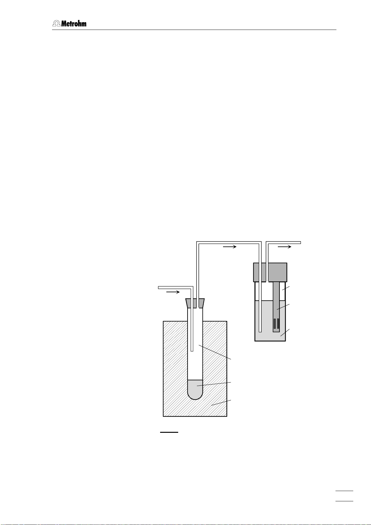
1.1 Determination of thermal stability
The determination of the thermal stability of polyvinyl chloride according
to DIN 53 381, part 1, is based on the fact that PVC decomposes at
higher temperatures with the release of HCl. The hydrochloric acid
formed is taken up by a gas stream (normally N2) and transferred into
the measuring vessel where it is absorbed in the measuring solution
(dist. water). The decomposition process is monitored by measuring
the conductivity of the aqueous HCl solution. Both the stability time and
the induction time are determined. The stability time is defined as the
time required to achieve a conductivity difference of 50 µS/cm. The in-
duction time is the time that elapses before the conductivity starts to
rise sharply. The method is used for testing PVC in all stages of processing as well as for testing stabilizers.
N
2
Reaction vessel
PVC
Heating block
Fig. 1: Schematic measuring arrangement
Measuring
vessel
Conductivity
measuring cell
Measuring
solution
763 PVC Thermomat 1
Page 9

1 Introduction
1.2 Instrument description
The 763 PVC Thermomat is a PC-controlled instrument for determining the thermal stability of PVC and similar halogenated plastics and is
available in the following two versions:
• 2.763.0014 PVC Thermomat for 230 V, 50……60 Hz
• 2.763.0015 PVC Thermomat for 115 V, 50……60 Hz
The 763 PVC Thermomat is equipped with two heating blocks each
with 4 measuring positions. Each block can be individually heated, i.e.
2 sets of 4 samples can be measured at two different temperatures or 8
samples can be measured at the same temperature. Measurements at
the individual measuring positions can be started individually.
The complete operation of the 763 PVC Thermomat is carried out via a
PC connected to the RS232 interface with the aid of the «763 PVC
Thermomat» control and evaluation program. Up to 4 instruments can
be connected to 1 PC allowing a maximum of 32 samples to be analyzed at the same time. The evaluation algorithm of the PC program
determines the point of inflection of the Thermomat curve and therefore
the induction time fully automatically. Apart from the induction time,
the so-called stability time, i.e. the time taken until a certain alteration
in the conductivity is reached, can also be determined. The results obtained can be subjected to further mathematical processes. In particular, induction times can be converted to the standard temperatures
contained in the relevant standards.
Each Thermomat curve can also be evaluated manually. A PC-supported tangent method is available for this in which the tangents can be
applied to the curve as required. This means that evaluations are possible even in extreme cases.
The results of the determinations are stored in a database together
with all the data concerning the method and determination. In the results display part of the program determinations can be searched for,
sorted, filtered, exported and printed out. Apart from the graphical display of single and multiple curves it is also possible to carry out recalculations with altered parameters and to extrapolate the results to a
particular temperature.
GLP (Good Laboratory Practice) and instrument validation are continuously increasing in importance. In the 763 PVC Thermomat GLP tests
are provided for the measurement of temperature, conductivity and gas
flow. They determine whether and which tests are to be carried out. The
time interval between the tests and the required accuracy can also be
laid down as required. If the GLP function is selected then on each result report a remark will be made as to whether the GLP test requirements have been fulfilled. As an option Metrohm offers a GLP test set
(6.5616.000), with which the most important tests can be carried out.
763 PVC Thermomat2
Page 10
1.3 Operating elements
1.3 Operating elements
77
88
99
1010
1111
763 PVC Thermomat
66
55
44
33
22
11
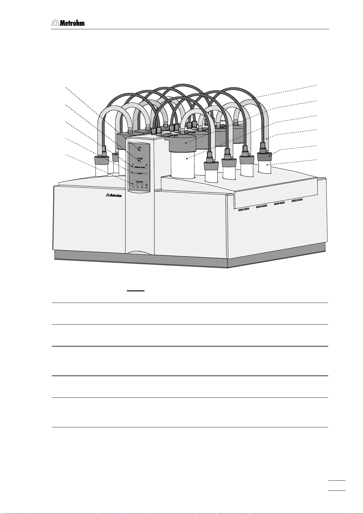
Fig. 2: Front of the 763 PVC Thermomat
11 Reaction vessel (6.1429.040) 77 Mains pilot lamp
lit up when instrument switched on
22 Reaction vessel cover (6.2753.100) 88 Gas flow display
lit up when gas flow switched on
33 Connecting tubing (6.1816.010)
between reaction vessel and measuring
vessel
44 Measuring vessel (6.1428.100) 1010 Error display (red)
55 Measuring vessel cover (6.0913.130)
with built-in conductivity measuring cell
66 Connecting tubing (6.1805.080)
for gas supply into reaction vessel
99 Temperature display
flashes when heating switched on
lit up when temperature reached
lit up at error
1111 Instrument display
indicates numbers (1…4) of units
connected
763 PVC Thermomat 3
Page 11
1 Introduction
2121
Made by Metrohm Herisau Switzerland
2020
1919
Type:
Nr.:
f:
U:
S:
N in
Fuse
100-115V: 4A(TH)
220-240V: 2A(TH)
WARNING - Fire Hazard -
For continued protection replace only
with the same type and rating of fuse
RS 232
Pt 100
1212 1313 1414 1515 1616 1717 1818
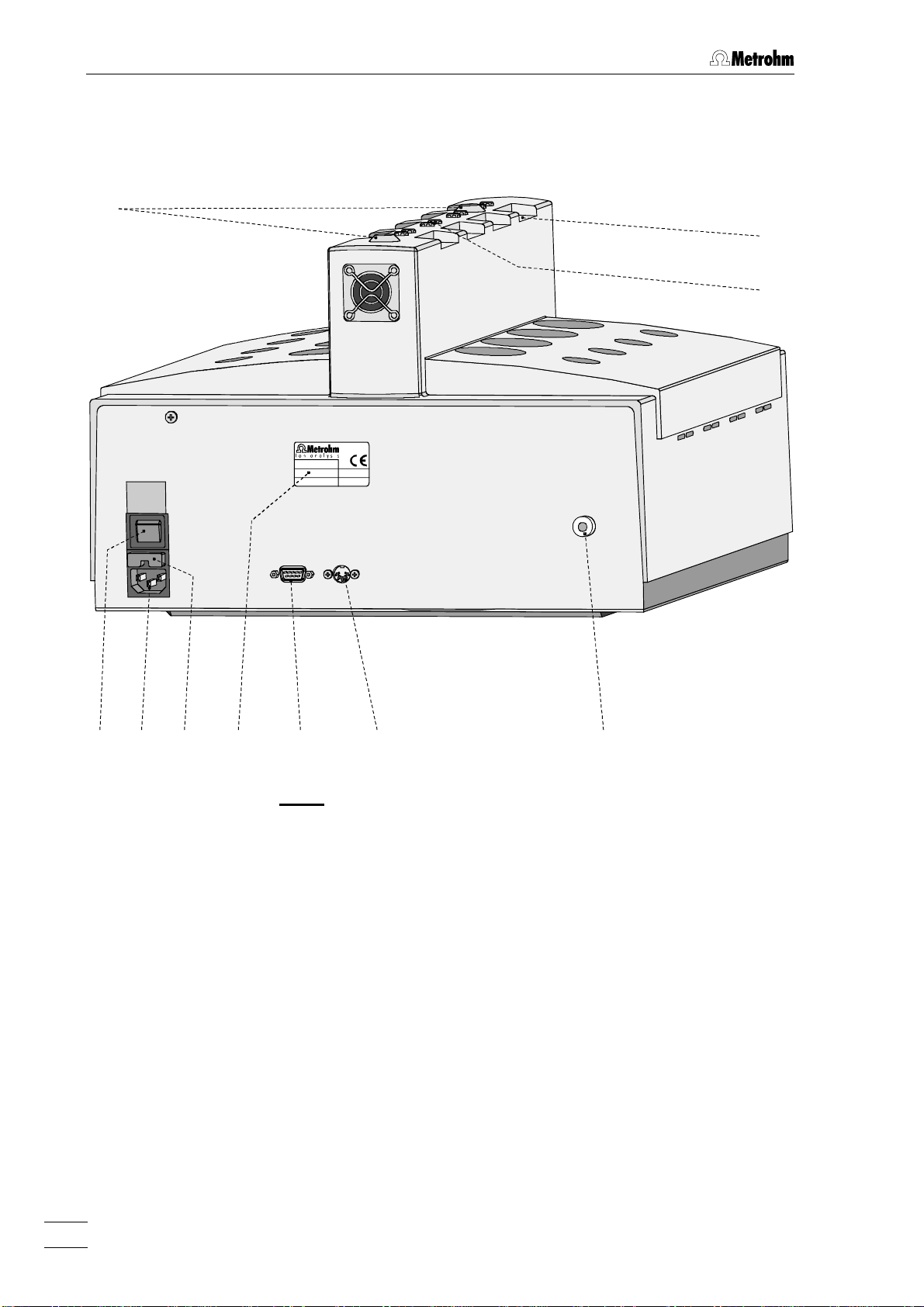
Fig. 3: Rear of the 763 PVC Thermomat
2
763 PVC Thermomat4
Page 12

1212 Mains switch
to switch instrument on and off:
I = ON 0 = OFF
1313 Mains connection plug
mains connection, see section 2.3
1414 Fuse holder
changing the fuses, see section 2.3
1515 Model plate
indicating mains voltage and serial
number
1616 PC connection
RS232 interface
1.3 Operating elements
1717 Pt100 connection
Connection for external temperature
sensor
1818 Connection "N2 in"
1919 Gas supply connection
for connection tubing 66
2020 Electrode connection
for measuring vessel cover 55
2121 Mounting
for 6.2757.000 Exhaust collection tube
(option)
763 PVC Thermomat 5
Page 13

1 Introduction
1.4 Information about these Instructions for Use
Please read through these Instructions for Use carefully before you put
the 763 PVC Thermomat into operation. The Instructions for Use
contain information and warnings to which the user must pay attention
in order to assure safe operation of the instrument.
1.4.1 Organization
These 8.763.1003 Instructions for Use for the 763 PVC Thermomat
provide a comprehensive overview of the installation, startup procedure, operation, fault rectification and technical specifications of this instrument. The Instructions for Use are organized as follows:
Section 1 Introduction
Measuring method, description of instrument,
operating elements and safety notes
Section 2 Installation
Installation of accessories, mains connection,
connection to PC
Section 3 Operating tutorial
Introduction to the operation using an example
Section 4 Operation
Detailed description of the operation
Section 5 Maintenance – Faults
Maintenance, fault display and fault rectification
Section 6 Appendix
Technical data, standard equipment, options, warranty, declarations of conformity, index
To find the required information on the instruments, you will find it an
advantage to use either the Table of contents or the Index at the
back.
You will find additional information on the PVC Thermomat method in
the relevant "Application Bulletins", which are available on request
free of charge from your Metrohm agency, as well as in the
"Application Notes" concerning the PVC Thermomat method, which
can be downloaded from the Internet under «www.metrohm.ch».
763 PVC Thermomat6
Page 14
1.4.2 Notation and pictograms
The following notations and pictograms (symbols) are used in these Instructions for Use:
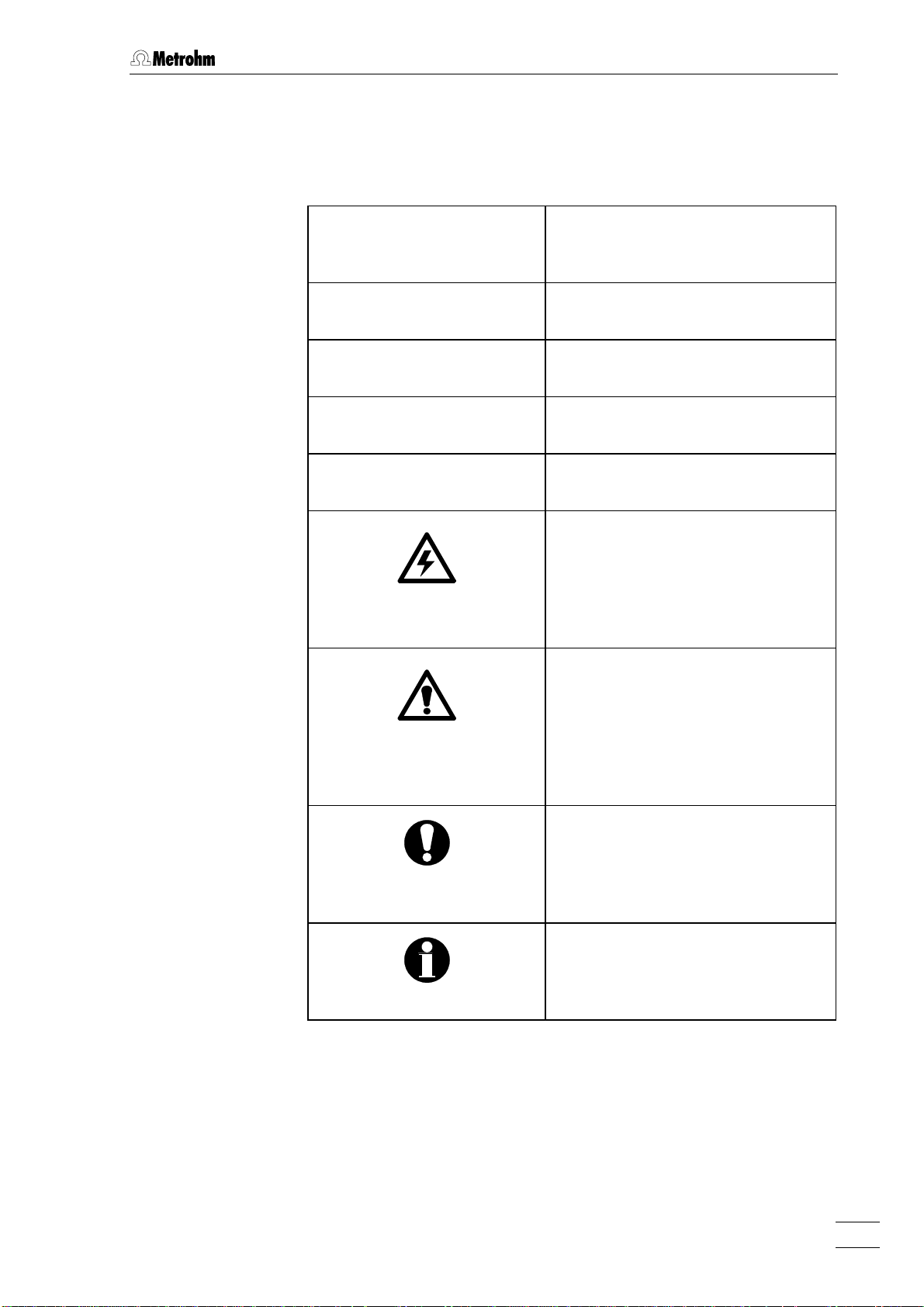
Range Menu item, parameter or
763 PVC THERMOMAT RESULTS Program window
<OK> Button
[ Ctrl ] Key
3535 Operating element of 763
1.4 Information about these Instructions for Use
entry value
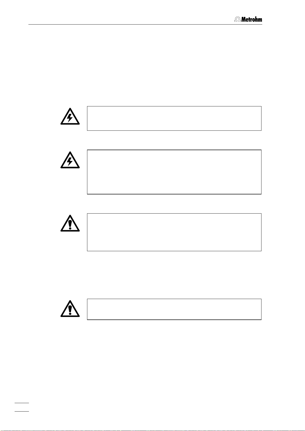
Hazard
This symbol draws attention to a
possible danger to life or of injury if
the associated directions are not
followed correctly.
Warning
This symbol draws attention to
possible damage to instruments or
instrument parts if the associated
directions are not followed correctly.
Caution
This symbol marks important information. First read the associated
directions before you continue.
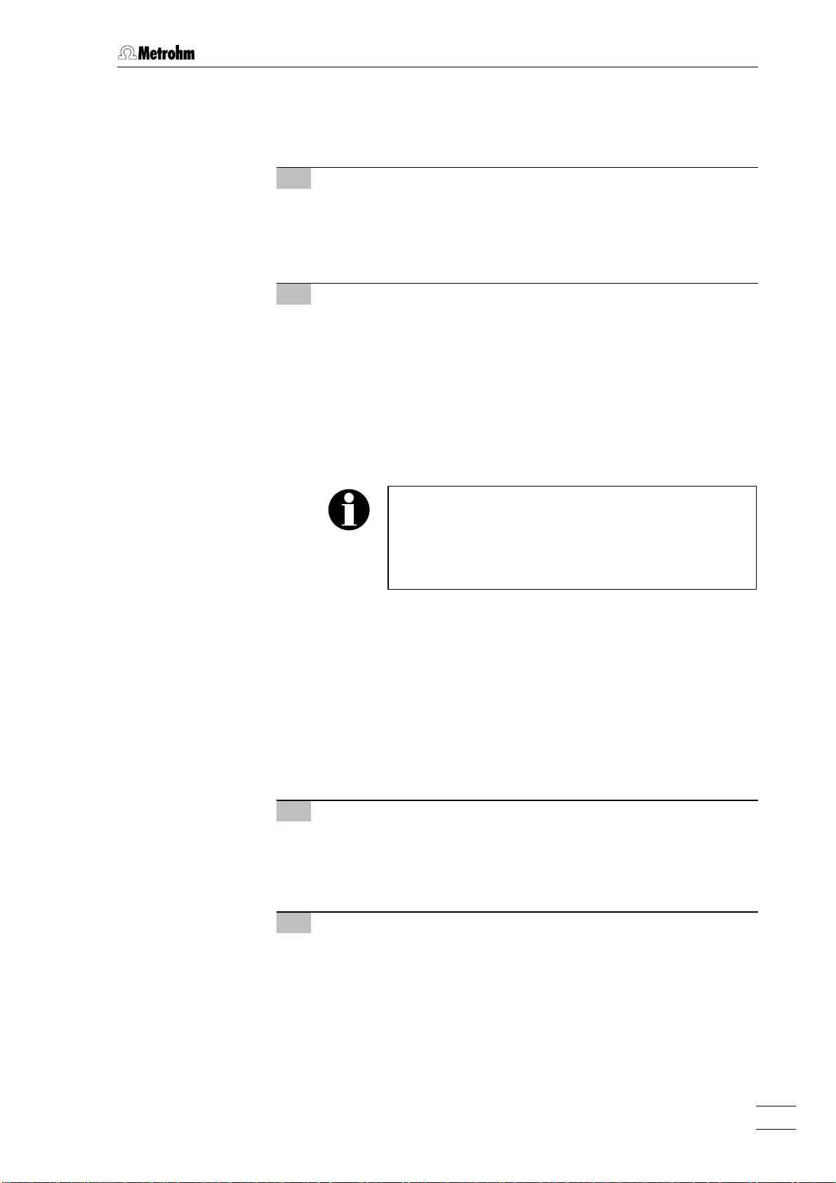
Comment
This symbol marks additional information and tips.
763 PVC Thermomat 7
Page 15
1 Introduction
1.5 Safety notes
1.5.1 Electrical safety
While electrical safety in the handling of the 763 PVC Thermomat is assured in the context of the specifications IEC 1010-1 (protection class 1,
degree of protection IP20), the following points should be noted:
• Mains connection
Setting of the mains voltage, checking the mains fuse and the
mains connection must be effected in accordance with the instruc-
tions in section 2.3.
• Opening the 763 PVC Thermomat
If the 763 PVC Thermomat is connected to the power supply, the
instrument must not be opened nor must parts be removed from it,
otherwise there is a danger of coming into contact with components
which are live. Hence, always disconnect the instrument from all
voltage sources before you open it and ensure that the mains cable
is disconnected from mains connection 1313 !
• Protection against static charges
Electronic components are sensitive to static charging and can be
destroyed by discharges. Before you touch any of the components
inside the 763 PVC Thermomat, you should earth yourself and any
tools you are using by touching an earthed object (e.g. housing of the
instrument or a radiator) to eliminate any static charges which exist.
1.5.2 General precautionary rules
• Take care with hot reaction vessels
Avoid any contact with hot reaction vessels. Place them in the supplied vessel holder to cool them down.
763 PVC Thermomat8
Page 16

2 Installation
2.1 Setting up the instrument
2.1.1 Packaging
The 763 PVC Thermomat is supplied together with the separately
packed accessories in special packaging containing shock-absorbing
foam linings designed to provide excellent protection. The instrument
itself is packed in an evacuated polyethylene bag to prevent the ingress
of dust. Please store all these special packaging as only they assure
transport of the instrument free from damage.
2.1.2 Check
2.1 Setting up the instrument
2.1.3 Location
After receipt, immediately check whether the shipment is complete and
has arrived without damage (compare with delivery note and list of
accessories in section 6.2). In the case of transport damage, see
instructions in section 6.4.1 "Warranty".
Position the instrument in the laboratory at a location convenient for operation, free from vibrations and protected against a corrosive atmosphere and contamination by chemicals. It is advisable to set up the instrument in a fume cupboard to guard against odor emission, but the
PC can be positioned outside on the regular laboratory bench.
In order to improve accessibility to the measuring places the instrument can also be placed on the 6.2059.000 Rotation ring, which is
available as an option.
763 PVC Thermomat 9
Page 17

2 Installation
2.2 Attaching the accessories
2.2.1 Accessories for external gas supply
Nitrogen (N2) is required for external gas supply to the 763 PVC Thermomat. The following accessories must be mounted on the rear panel
of the PVC Thermomat:
1 Fitting the connecting tubing
• Screw one end of connecting tubing 6.1805.030 (150 cm)
onto connection 1818 "N2 in" on the rear panel of the PVC
Thermomat (see Fig. 3).
• Screw the 6.1808.020 connection piece onto the other end of
connecting tubing 6.1805.030.
2 Connect up gas supply
• Attach the gas supply from the cylinder containing nitrogen to
the tubing nozzle of 6.1808.020 Connection piece.
• Set gas pressure at the nitrogen cylinder to ca. 1.5 bar using
the reducing valve.
2.2.2 Reaction and measuring vessels
Fig. 4 shows the details of how the accessories for measuring the thermal stability are to be attached and connected to each other. Proceed
as follows:
1 Fitting the measuring vessel cover
• Insert PTFE tube 2727 from above into opening 2424 "In" of
measuring vessel cover 55.
• Screw connection piece 2222 into opening 24 24 of measuring
vessel cover 55.
2 Inserting the measuring vessel in the instrument
• Fill 60 mL dist. water into measuring vessel 44.
• Place measuring vessel cover 55 on measuring vessel 44.
• Insert measuring vessel 44 with attached measuring vessel
cover 55 into the opening provided for it on the 763 PVC
Thermomat and connect measuring vessel cover 55 with con-
nection plug 2626 to electrode connection 2020 (see Fig. 3).
3 Fitting the reaction vessel
• Insert gas inlet tube 3232 from below into connection 3434 of
reaction vessel cover 22.
• Push sealing ring 3333 over the upper end of gas inlet tube 3232.
• Screw connection nipple 3030 loosely into connection 3434 and
press gas inlet tube 3232 against connection nipple 3030 from
below; then fix gas inlet tube 3232 to reaction vessel cover 22 by
firmly tightening connection nipple 3030.
763 PVC Thermomat10
Page 18
2.2 Attaching the accessories
• Place reaction vessel cover 22 on reaction vessel 11.
• Connect the white connecting tubing 33 to connection 3131 of
reaction vessel cover 22 (see Fig. 3).
4 Inserting the reaction vessel into the instrument
• Place the sample in the reaction vessel (see section 4.6.2).
• When the required temperature has been reached insert
reaction vessel 11 with attached reaction vessel cover 22 in the
openings provided for it on the 763 PVC Thermomat.
5 Making the tubing connections
• Connect the white connecting tubing 3 3 attached to reaction
vessel cover 22 to connection piece 2222 of measuring vessel
cover 55.
• Screw one end of brown connecting tubing 66 to connection
nipple 3030 of reaction vessel cover 22.
• Screw the other end of brown connecting tubing 66 to the
corresponding connection 1919 on the 763 PVC Thermomat
(see Fig. 3).
The 6.1428.020 transparent glass measuring vessel
available as an option can be used instead of the
6.1428.100 polycarbonate measuring vessel; in
contrast to the polycarbonate vessel this can be
cleaned with acetone.
2.2.3 Exhaust collection tube (option)
For selective exhaust lead off the 6.2757.000 Exhaust collection
tube available as an option can be fitted to the 763 PVC Thermomat. In
addition to the exhaust collection tube 8 x 6.1816.010 Silicone tubing
(22 cm) must also be ordered. Attach the exhaust collection tube as
described below:
1 Positioning the exhaust collection tube
• Place the exhaust collection tube with the two supports in the
two mountings 2121 (see Fig. 3) on the 763 PVC Thermomat so
that the connection for leading off the exhaust is located to
the rear.
2 Connecting the measuring vessel
• Screw a connection piece 2222 into opening 2323 of the measur-
ing vessel cover 55.
763 PVC Thermomat 11
Page 19
2 Installation
66
3030
3131
3232
3333
3434
33
2222
2323
2424
2525
2626
55
22
2727
2828
2929
11
44
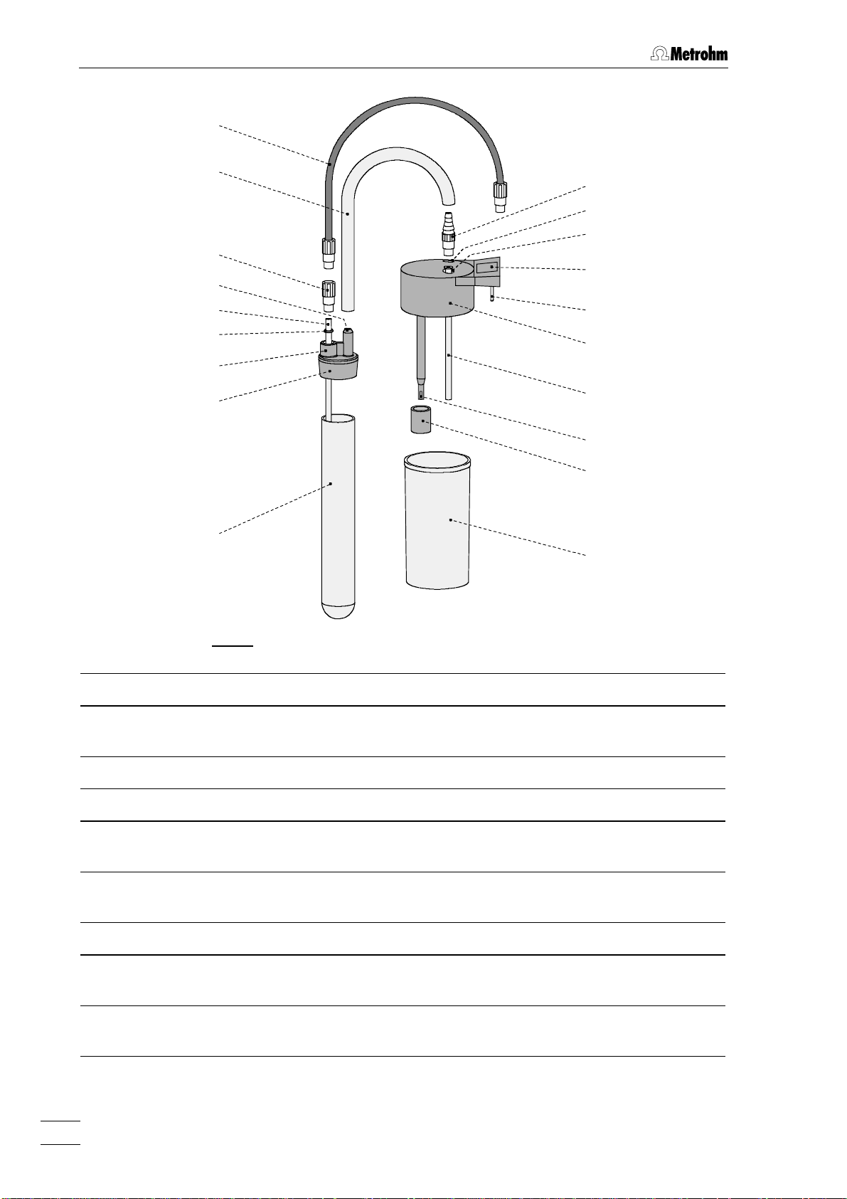
Fig. 4: Installation of reaction and measuring vessels
11 Reaction vessel (6.1429.040) 2626 Connection plug
22 Reaction vessel cover (6.2753.100) 2727 PTFE tube (6.1819.080)
for air supply into measuring vessel
33 Connecting tubing (6.1816.010) 2828 Electrodes
44 Measuring vessel (6.1428.100) 2929 Protective ring (4.422.0520)
55 Measuring vessel cover (6.0913.130)
with built-in conductivity measuring cell
66 Connecting tubing (6.1805.080)
for gas supply to reaction vessel
2222 Connection piece (6.1808.050) 3232 Gas inlet tube (6.2418.110)
2323 Opening "Out"
for measuring vessel exhaust
2424 Opening "In"
for measuring vessel inlet
3030 Connection nipple (6.1808.090)
3131 Connection
for connecting tubing 33
3333 Sealing ring (6.1454.040)
3434 Connection
for connection nipple 3030
2525 Marking field
for entering the cell constant
763 PVC Thermomat12
Page 20
• Connect one end of the 6.1816.010 Silicone tubing to connection piece 2222.
• Plug the other end of the 6.1816.010 Silicone tubing into the
corresponding exhaust collection tube opening.
• Close the unused openings on the exhaust collection tube
with the included E.400.0010 stoppers.
3 Connecting the exhaust collection tube
• Attach a piece of suitable tubing to the exhaust collection
tube connection and connect it to an active aspirating device
(e.g. water-jet pump).
2.3 Mains connection
2.3 Mains connection
Follow the instructions below for connecting to the power supply. If
the instrument is operated with a mains voltage set wrongly and/or
wrong mains fuse, there is a danger of fire!
2.3.1 Checking the mains voltage
Before switching on the 763 PVC Thermomat for the first time, check
that the mains voltage indicated on the model plate 1515 (see Fig. 3)
matches the local mains voltage. If this is not the case, call the
Metrohm service.
2.3.2 Exchange of fuses
Two fuses 4 A/slow-blow for 115 V or 2 A/slow-blow for 230 V are installed in fuse holder 1414 of the 763 PVC Thermomat as standard.
Ensure that the instrument is never put into operation with fuses of
another type, otherwise there is danger of fire!
For changing fuses, proceed as follows:
1 Disconnect mains cable
Disconnect mains cable from mains connection plug 1313 of the
763 PVC Thermomat.
2 Remove fuse holder
Using a screwdriver, loosen fuse holder 1414 above the mains
connection plug 1313 and take out completely.
763 PVC Thermomat 13
Page 21
2 Installation
3 Change fuses
Remove old fuses carefully from fuse holder 1414 and replace
them with two new fuses which are suitable for the set mains
voltage, type TH (slow-blow, with high switching capacity):
115 V 4 A (TH) Metrohm-No. U.600.0022
230 V 2 A (TH) Metrohm-No. U.600.0107
4 Install fuse holder
Push fuse holder 1414 back into the instrument until it clicks into
position.
2.3.3 Mains cable and mains connection
Mains cable
The instrument is supplied with one of three mains cables
• 6.2122.020 with plug SEV 12 (Switzerland, …)
• 6.2122.040 with plug CEE(7), VII (Germany, …)
• 6.2133.070 with plug NEMA 5-15 (USA, …)
which are three-cored and fitted with a plug with an earthing pin. If a
different plug has to be fitted, the yellow/green lead (IEC standard)
must be connected to protective earth (protection class 1).
Any break in the earthing inside or outside the instrument can make it
a hazard!
Mains connection
Plug the mains cable into mains connection plug 1313 of the 763 PVC
Thermomat (see Fig. 3).
2.3.4 Switching the instrument on/off
The 763 PVC Thermomat is switched on and off using mains switch 1212.
When the instrument is switched on, the mains pilot lamp 77 "ON" (see
Fig. 2) lights up.
763 PVC Thermomat14
Page 22

2.4 Connection to the PC
2.4.1 Connection PVC Thermomat – PC
Always switch off 763 PVC Thermomat and PC before you connect the
two instruments with the 6.2134.100 Cable.
The PC program «763 PVC Thermomat» allows a maximum of 4 PVC
Thermomats to be controlled. The following possibilities exist for connecting these PVC Thermomats to serial PC interfaces:
• Connection to built-in COM interfaces on the PC
• Connection to an additional built-in interface extension board
• Connection to a softswitch (order number: 2.145.0014 for 230 V,
2.145.0015 for 115 V) which is connected to one of the COM interfaces.
Connect the PC connection 1616 at the 763 PVC Thermomat to one of the
serial COM ports at the PC or to a softswitch using the 6.2134.100 Cable (9 pin/9 pin). If only a 25-pin COM interface is available on the PC
then the 6.2125.110 Adapter cable or a commercially available adapter
must be used.
2.4 Connection to the PC
2.4.2 Software installation
The PC program «763 PVC Thermomat 1.0» is required for the operation of the 763 PVC Thermomat; this is contained on the 6.6037.000
CD included in the accessories. This program runs under Windows NT
(recommended, especially if several instruments are connected), Windows 95 and Windows 98 operating systems and is installed as follows:
1 Install program
• For Windows NT: log in as operator with administrator rights.
• Insert 6.6037.000 Installation CD into CD drive.
• Select <Start> and Run. Browse for the setup.exe file on the
installation CD and click on <OK>.
• Click on "763" and follow the instructions given in the setup
program.
The software package will be installed in the desired directory. In addition to the program files, the following folders are
installed:
Database Folder for database files (*.mrd)
Log Folder for event log files (*.mel) and temperature
Template Folder with empty database (Default.mrd) and
recording files (*.txt)
copy of the result program (Nachaus.prg)
2 Registration
• Please send us your 8.763.8007 Registration card as soon as
possible.
763 PVC Thermomat 15
Page 23
2 Installation
2.4.3 Basic settings
When the program is started for the first time several basic settings
must be made for the 763 PVC Thermomat. Proceed as follows:
1 Switch on instruments
2 Start program and login
• Check if the PVC Thermomat has been connected correctly to
the PC (see section 2.4.1).
• Switch on the PVC Thermomat using mains switch 1212.
• Switch on the PC.
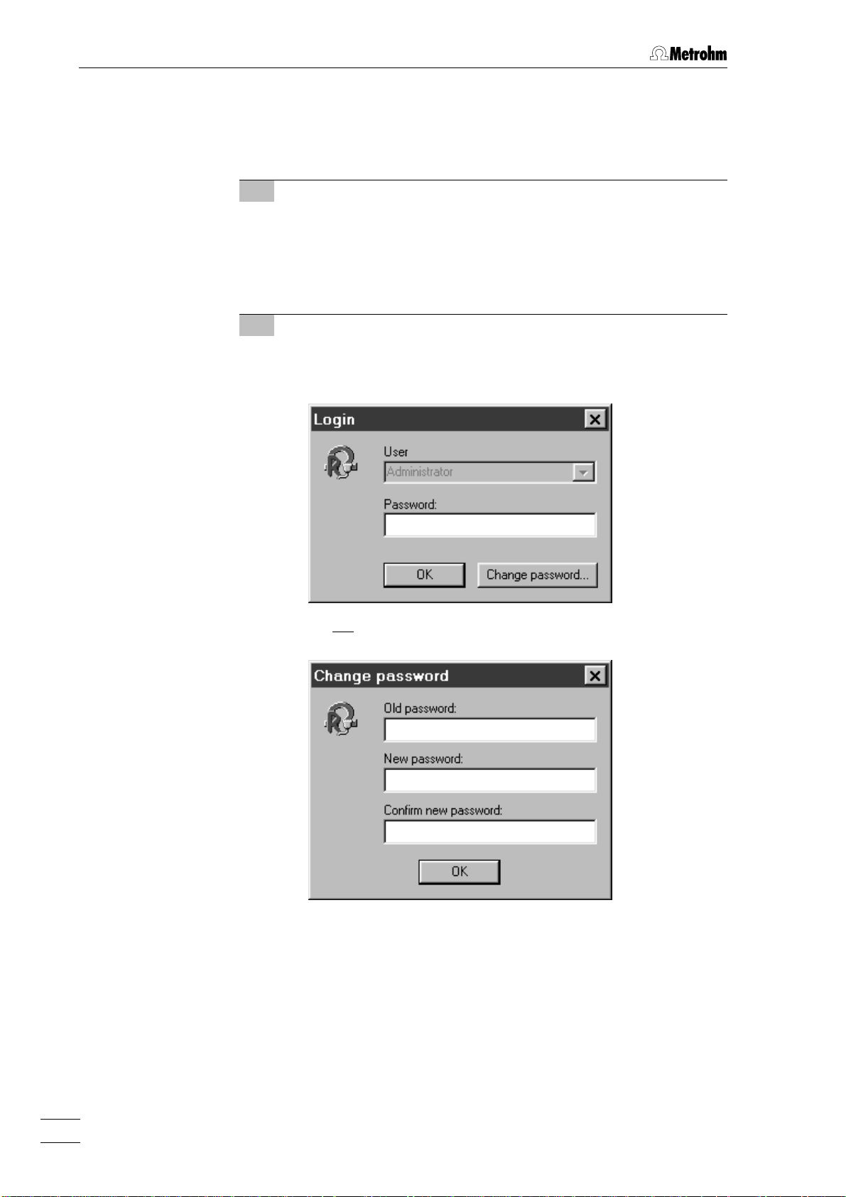
• Double-click the software icon to start the program. The
program window with the opening picture is opened and the
Login window appears on the screen:
• Do not enter any password here, just click on <Change pass-
word>. The following window appears:
• Leave the Old password field empty. Under New password enter
the required password which will in future allow you to log in
as Administrator. Confirm the new password by renewed entry
in the Confirm new password field and click on <OK>.
• Enter the new Password again in the Login window. You are
now logged in as Administrator.
• Confirm the message There are no units configured yet with
<OK>. The 763 PVC THERMOMAT CONTROL window appears.
763 PVC Thermomat16
Page 24
2.4 Connection to the PC
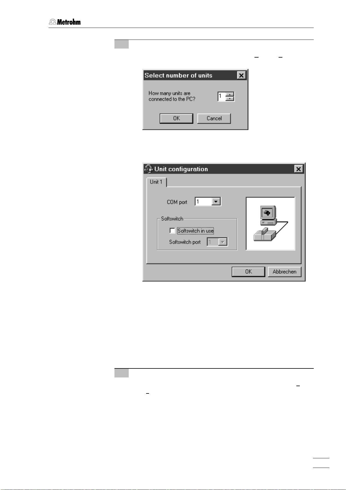
3 Communication settings
• Click on 763 PVC THERMOMAT CONTROL / Options / Communica-
tion to open the Select number of units window:
• Enter the number of PVC Thermomats (1…4) connected to
the PC and click on <OK>. The Unit configuration window appears:
• Under COM port select for each instrument the number of the
serial interface (1…8) to which this instrument is connected. If
a softswitch is used then the option Softswitch in use must be
switched on. Under COM port the number of the serial interface to which the softswitch is connected is selected; under
Softswitch port the number of the interface on the softswitch to
which the instrument is connected is selected.
• Click on <OK> to close the Unit configuration window.
• Confirm the message which then appears with <OK>.
4 Close the program and start it up again
• Close the program with 763 PVC THERMOMAT CONTROL / File /
Exit.
• Restart the «PVC Thermomat 1.0» program by double-
clicking the program icon.
• In the Login window enter the Password for the administrator.
The control window appears. In the status line the message
Unit#: Ready should appear for all connected instruments.
763 PVC Thermomat 17
Page 25

2 Installation
763 PVC Thermomat18
Page 26
3 Operating tutorial
This section introduces you to the operation of the 763 PVC Thermomat by means of a brief operating tutorial which describes the basic
operating steps needed for performing determinations and display of
results.
For further explanations of the operation, please refer to section 4.
3.1 Determinations
3.1 Determinations
The determination of induction and stability time of a PVC sample at
200 °C and a gas flow of 7 L/h is used an illustrative example. Please
note that the steps and parameter settings described apply only to
this example. If you use a different sample and different parameters,
the procedures described in the tutorial must be modified appropriately.
3.1.1 Installation
Before you start this brief tutorial, the 763 PVC Thermomat must be
correctly installed as described in section 2. In what follows, the most
important points for the installation are listed once again (for details,
see the sections mentioned).
⇒ Setting up instrument section 2.1
⇒ Installing air supply accessories section 2.2.1
⇒ Installing reaction and measuring vessels section 2.2.2
⇒ Mains connection section 2.3
⇒ Connection to PC section 2.4
763 PVC Thermomat 19
Page 27
3 Operating tutorial
3.1.2 Preparing for determinations
Before starting determinations, the method must be selected, the
heating must be started and the reaction and measuring vessels must
be prepared. Proceed as follows:
1 Switch on 763 PVC Thermomat
⇒ Switch on 763 PVC Thermomat with mains switch 1212 on the
rear of the instrument. After the instrument has been switched
on the mains pilot lamp 77 lights up.
2 Switch on PC
⇒ Switch on PC and start «763 PVC Thermomat» program.
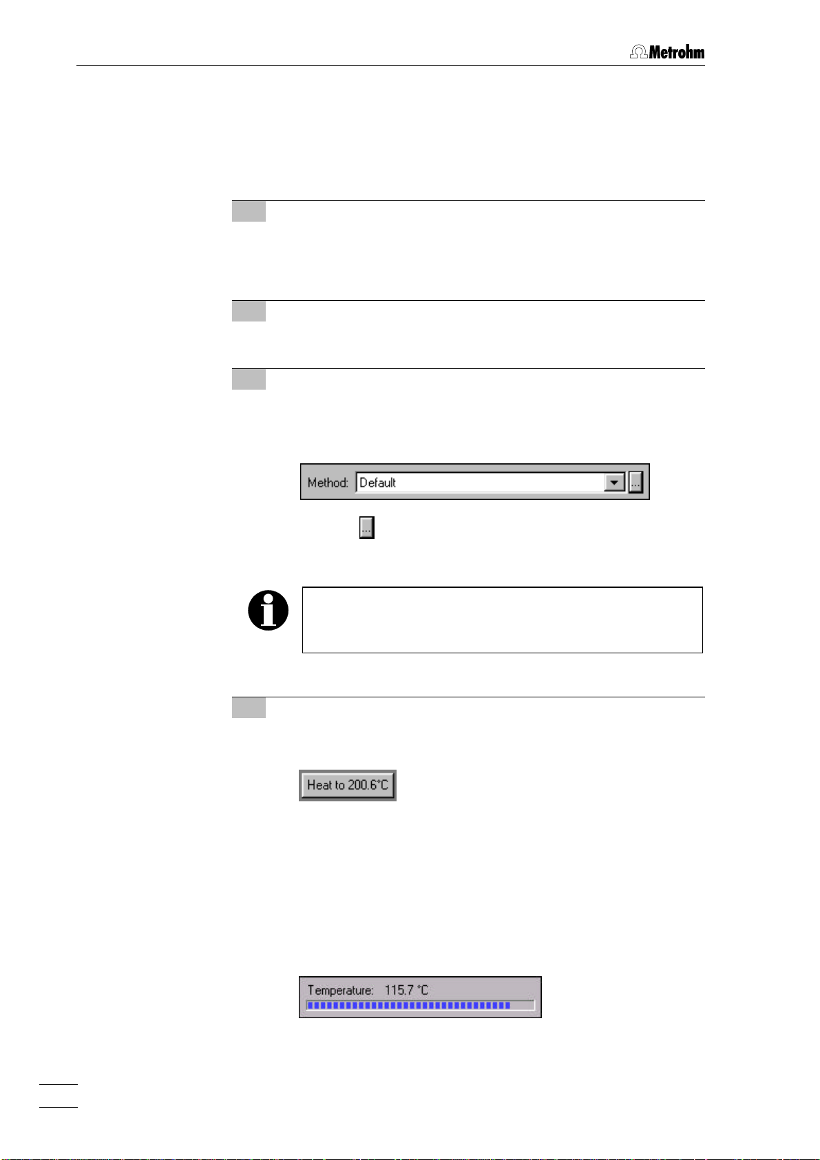
3 Select method "Default"
⇒ In the opened control window, select the determination
method Default for Block A (and – if more than 4 samples are
to be determined – also for Block B) in the Method field.
⇒ Click on , if you want to change the parameters of the
default method (details see section 4.5.2).
The determinations described in this tutorial have been
carried out using the default settings (Temperature = 200 °C,
Delta T = 0.6 °C, Gas flow = 7 L/h, etc.).
4 Start heating
⇒ To start the heating of Block A and – if desired – of Block B
click on the following button:
As soon as the heating is switched on the color of the frame
of this button switches to red. At the same time the temperature display 99 "TEMPERATURE" LED on the 763 PVC Ther-
momat starts to blink for the selected block.
The actual temperature is shown digitally beside the button. A
bar below shows the absolute variation of the actual temperature from the target temperature; the bar length corresponds to 50 °C.
763 PVC Thermomat20
Page 28
3.1 Determinations
5 Prepare measuring vessels
⇒ Clean the used measuring vessels and their covers (details
see section 4.6.3).
⇒ Fill each cleaned measuring vessel 4 4 with 60 mL distilled
water.
⇒ Place the measuring vessel cover 55 fitted with a PTFE tube
2727 on the measuring vessel 44 (see Fig. 4).
⇒ Place the measuring vessel 44 with its cover 55 in one of the
openings provided for it on the 763 PVC Thermomat and
connect the electrode plug 2626 on the cover to the corre-
sponding socket 2020 on the 763 PVC Thermomat.
6 Prepare reaction vessels
⇒ Weigh out 0.5 g PVC into the reaction vessels 1.
⇒ Take the upper rim of the reaction vessel 1 in your hand (e.g.
in the space between thumb and index finger) and rotate the
glass though 360°. This provides the degreased glass with a
thin grease film, without which it is very difficult to remove the
cover from the vessel after the determination.
⇒ Insert an gas inlet tube 32 into the reaction vessel cover 2
and fasten it by screwing down the connection nipple 30 (see
Fig. 4).
⇒ Place the reaction vessel cover 2 on the reaction vessel 1.
Rotate the cover so that the air inlet tube 32 is as close as
possible to the vessel wall.
⇒ Fasten the white connecting tubing 3 on to the connection 31
of the reaction vessel cover 2.
⇒ Place the prepared reaction vessel into the vessel holder.
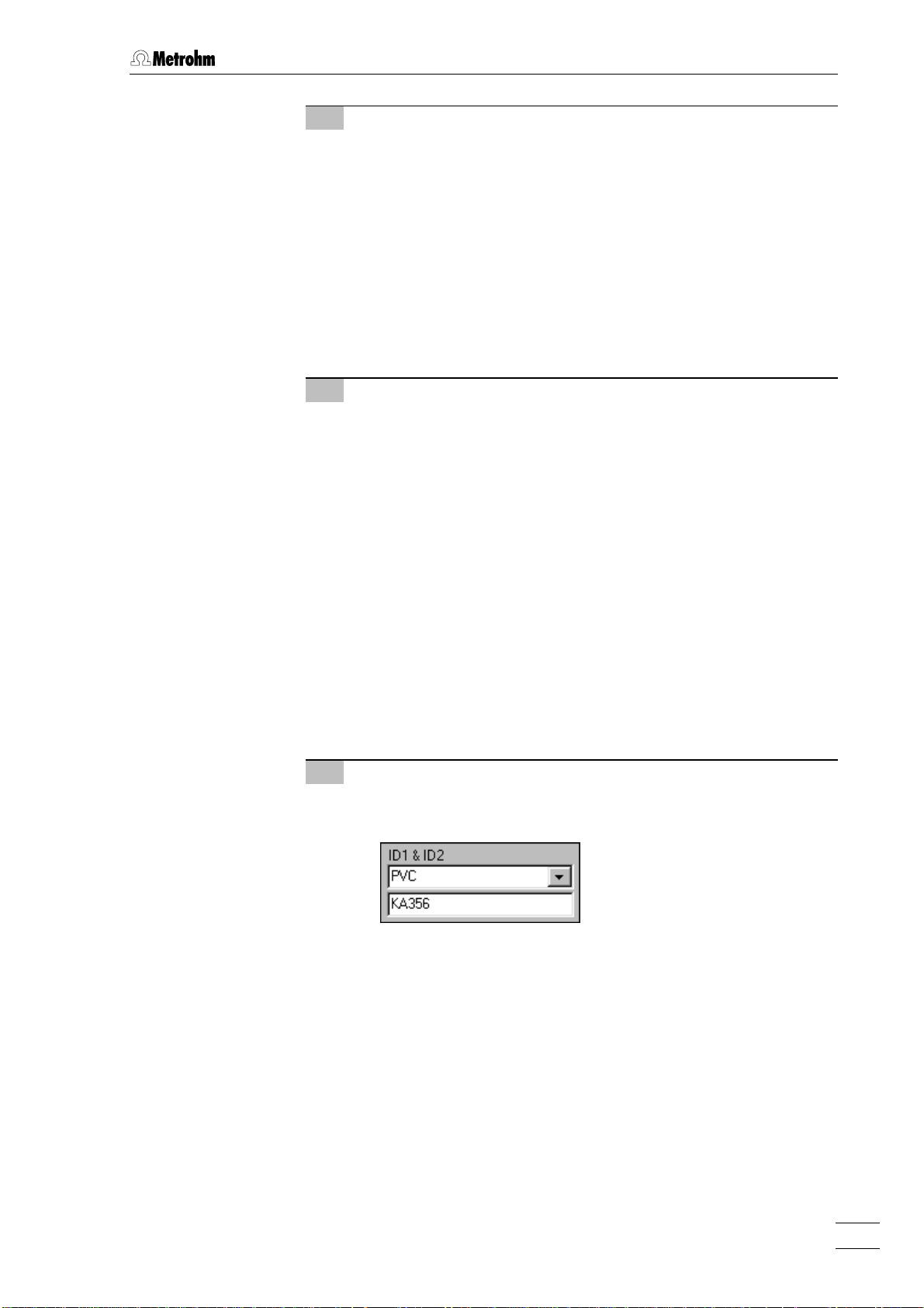
7 Enter sample identifiers
⇒ Enter the sample identifiers ID1 and ID2 in the corresponding
fields of the operating area in the control window.
763 PVC Thermomat 21
Page 29
3 Operating tutorial
3.1.3 Carrying out determinations
When the preparations are complete the determinations can be started.
Proceed as follows:
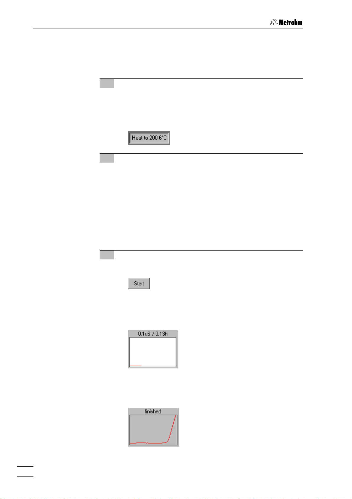
1 Wait until the temperature has been reached
⇒ Wait until the heating block reaches the temperature defined
in the method. This condition is indicated by temperature display 99 "TEMPERATURE" which stops blinking and remains
lit up. At the same time or after a slight delay the frame color
of the <Heat to...> button turns green.
2 Insert reaction vessels
⇒ Place the prepared reaction vessels 11 in the heating block
openings on the 763 PVC Thermomat. Close any openings
which are not used with stoppers or empty reactions vessels
to protect against contamination.
⇒ Connect the white connecting tubing 33 fastened to the reac-
tion vessel cover 22 to the corresponding connection 2222 on
the measuring vessel cover 55.
⇒ Screw the brown gas supply tubing 66 onto the connection
nipple 3030 of the reaction vessel cover 22 and the correspond-
ing connection 1919 on the 763 PVC Thermomat (see Fig. 3).
3 Start determination
⇒ In the operating field of the control window for every determi-
nation you want to start you must click on the button
.
After the start of a determination the live curve of the started
determination is shown in the operating window beside the
channel number. The actual measured value appears above
the curve.
As soon as a point of inflection is found during the measurement the determination is terminated. The window with the
live curve becomes gray again and the message finished appears.
763 PVC Thermomat22
Page 30
4 Automatic report output
GLP test passed.
At the end of the determination the report defined in the
method is printed out automatically.
3.1 Determinations
Unit
Block
Channel
1
A
1
ID 1
PVC
Induction time
Stability time
Standard time
200
175
150
125
100
µS/cm
75
50
25
Serial number
Cell constant
User
01109
1
Administrator
1.27
1.33
6.45
h
h
h
Druckdatum
Bestimmungsdatum
ID 2
KA356
Delta Kappa
(F: 2.254; T: 180°C)
09.09.1999 09:34:03
23.06.1999 13:25:52
50 µS/cm
1.27
1.33
0
0.00 0.25 0.50 0.75 1.00 1.25 1.50
Method name
Creator
Temperature
Delta T
Gas flow
Start delay
Start mode
PVC 200°C
Administrator
per channel
200
0.60 °C
7°CL/h
0
min
per 2 channels
per block
h
Creation date
Stop time
Stop at conductivity
Stopat endpoint
Delta Kappa
Evaluation delay
Evaluation suppression start
Evaluation suppression end
Send to file
23.06.1999 08:27:20
0.00
h
200
µS/cm
50
µS/cm
0.00
h
0.00
h
0.00
h
763 PVC Thermomat 23
Page 31

3 Operating tutorial
3.2 Results
The demo database Demo.mrd is used as an example for the display
and further processing of the results of recorded determinations.
Please note that the steps and parameter settings described apply
only to this database. If you use a different database, the procedures
described in the tutorial must be modified appropriately.
3.2.1 Determination overview
The determination overview displays an overview table with selected
data fields of all the determinations contained in the opened database.
1 Open database "demo.mrd"
⇒ Click on or File / Results in the control window in order to
open the 763 PVC THERMOMAT RESULTS window. This loads
the Repos.mrd database and opens the determination overview as standard.
⇒ Click on File / Open database in the results window. Select the
demo.mrd database in the Open database window and click on
<Open>. A sub-window opens in the results window which
shows the data from 5 determinations in an overview table.
2 Format determination overview
⇒ Select fields: Click on or Format / Select fields in the
results window. In the Display fields window move the fields
until the fields required for the determination overview are
visible in the Display field and then click on <OK>.
⇒ Adjust field width: Mark the column in the determination
overview whose width is to be altered. Click on Format / Adjust
width in the results window. Enter the column width in the Column width window or click on <Best fit> in order to automati-
cally adapt the column width to the longest field contents.
Alternatively the column width can also be set directly by using the mouse. This is done by moving the cursor between
two columns in the title line of the table until it appears as .
The column can now be pulled to the required width with the
left-hand mouse key pressed down. A double-click on the
763 PVC Thermomat24
Page 32

selected column automatically adapts the column width to
the longest field contents (including title).
⇒ Format fields: Click on Format / Fields in the results window.
Set down the format for the fields in the determination overview in the Cells effects window and click on <OK>.
⇒ Select fonts: Click on Format / Fonts in the results window.
Select the font to be used in the determination overview in the
Font window and click on <OK>.
⇒ Save settings: Click on Options / Save settings now to save
the new format of the determination overview permanently.
3 Print determination overview
⇒ Click on or File / Print in the results window to open the
Printing of window.
3.2 Results
⇒ Select Overview table if the determination overview is to be
printed out in tabular form.
⇒ Select Overview list if the determination overview is to be
printed out as a list with all the fields selected in the determination overview.
⇒ Click on <Print>.
⇒ In the Print window select the printer, printing area and num-
ber of copies and click on <Print>.
763 PVC Thermomat 25
Page 33

3 Operating tutorial
4 Export determination overview
⇒ Copy to clipboard: Mark the lines or columns in the deter-
mination overview which are to be copied. Click on or
Edit / Copy. The marked texts are loaded into the clipboard
from where they can be further processed with other programs.
⇒ Export to other database: Mark the determinations (lines)
which are to be exported in the determination overview. Click
on Determination / Export / Export to database. In the Export data
to... window select the database to which the determinations
are to be exported and click on <Save>.
⇒ Export to Word: Mark the lines or columns in the determina-
tion overview which are to be exported. Click on or De-
termination / Export / Export to MS Word. The marked texts are
loaded into an RTF file which is automatically opened with
Microsoft Word.
⇒ Export to Excel: Mark the lines or columns in the determina-
tion overview which are to be exported. Click on or De-
termination / Export / Export to MS Excel. The marked texts are
loaded into an XLS file which is automatically opened with
Microsoft Excel.
3.2.2 Determination and method data
All the determination and method data of each determination in a determination overview can be shown, printed out and exported.
1 Display determination and method data
⇒ In the opened determination overview mark the determination
for which all parameters and results are to be displayed.
⇒ Click on or View / Determination and method data in the
results window or double-click on the required line in the determination overview. The Determination and method data window opens in which the data are shown on several register
cards.
763 PVC Thermomat26
Page 34

3.2 Results
2 Print determination and method data
⇒ Click on or File / Print in the results window to open the
Printing of window (see section 3.2.1).
⇒ Select the All determination and method data option.
⇒ Click on <Print>.
⇒ In the Print window select the printer, printing area and num-
ber of copies and click on <Print>.
3 Export determination and method data
⇒ Mark the determinations (lines) in the determination overview
from which all data is to be exported.
⇒ Click on or Determination / Export / Determination and
method data.
⇒ In the Save to export file window select the required folder and
the file name of the *.txt export file under which the data are to
be stored and click on <Save>.
763 PVC Thermomat 27
Page 35

3 Operating tutorial
3.2.3 Graphics
Curves for each determination in a determination overview can be
shown, printed out and copied.
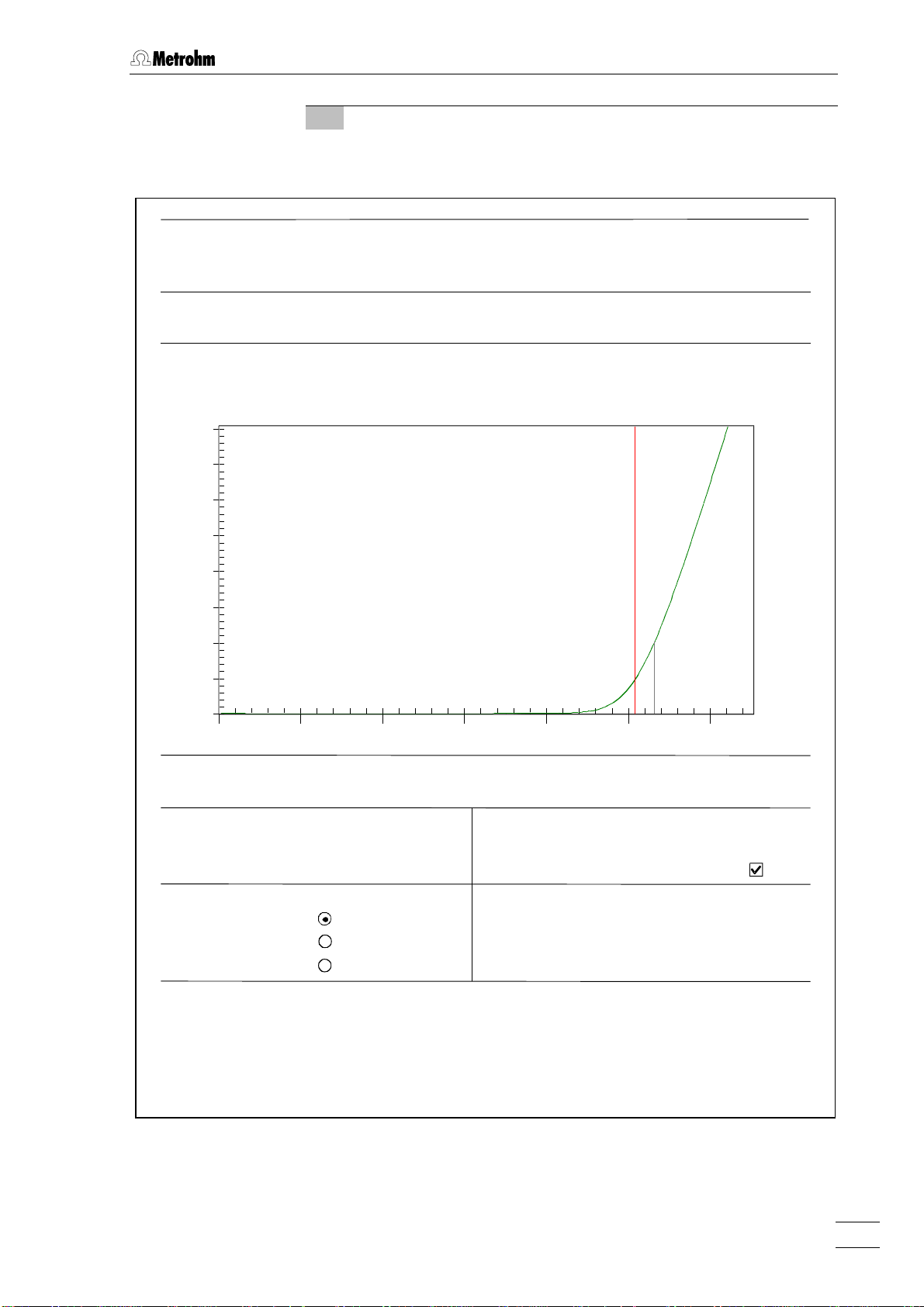
1 Open single graph
⇒ Mark the determination in the determination overview whose
single curve is to be displayed.
⇒ Click on or Determination / Graphics / Single graph in the
results window. A new window is opened in which the single
graph for the determination selected in the determination
overview is shown. The sample identifiers ID 1 and ID 2 are
shown in the window title. If present then the determined In-
duction time (red vertical line and numbers) and Stability time
(black vertical line and numbers) will be shown in the graphics window as well as the measuring curve (green).
2 Open multiple graph
⇒ Mark the determinations in the determination overview whose
curves are to be displayed in a multiple graph.
⇒ Click on or Determination / Graphics / Multiple graph in the
results window. A new window is opened in which all curves
for the determinations marked in the determination overview
are shown. The individual measuring curves are shown in
color, the legends referring to the colors (ID 1 and ID 2) are
located in the graph header. If present the determined Induc-
tion time ( ) and Stability time ( ) will also be shown.
763 PVC Thermomat28
Page 36

3 Open live graph
⇒ Mark the determination in the determination overview whose
curve is to be displayed.
3.2 Results
⇒ Click on or Determination / Graphics / Live graph with
reevaluation in the results window. A new window is opened in
which the measuring curve of the marked determination is
shown. If a different determination is marked in the determination overview then the curve is automatically updated. If
present then the determined Induction time (red vertical line
and numbers) and Stability time (black vertical line and numbers) will be shown in the graphics window as well as the
measuring curve (green). With <2nd derivative> the second
derivative of the measuring curve can be shown as a blue
line. The live graph offers the possibility of the manual ree-
valuation of the measuring curves (see section 4.7.3).
763 PVC Thermomat 29
Page 37

3 Operating tutorial
4 Print graphics
⇒ Open the required graph in the results window which is to be
printed.
⇒ Click on or File / Print in the results window. The curve
shown in the active graph window will be printed out.
⇒ If you want to print several single or multiple curves at the
same time first mark the required determinations in the determination overview. Click on or File / Print (see sec-
tion 3.2.1). In the Printing of... window select the option Single
graph or Multiple graph and click on <Print>.
5 Copy graphics
⇒ Open the required graph in the results window which is to be
copied.
⇒ Use the right-hand mouse key to click on the graph window
and select the option Copy in the context-sensitive menu. The
selected curve is copied into the clipboard where it can be
further processed with other programs.
763 PVC Thermomat30
Page 38

4.1 Fundamentals of the operation
4 Operation
This section describes the most important points concerning the
operation of the 763 PVC Thermomat. For further details please refer
to the on-line help in the PC program which can provide you with the
required information rapidly and conveniently from any place in the
program.
4.1 Fundamentals of the operation
4.1.1 Starting/closing the program
Start the «763 PVC Thermomat» program
Start the program
Double-click this icon or the PvcTm.exe file to start the «763 PVC
Thermomat 1.0» program. The Login window appears:
Select the desired User name and enter the Password. Then click
on <OK>.
After software installation, the program can be
started without entering a Password. For the definition of users, see section 4.2.2.
Close the «763 PVC Thermomat» program
763 PVC THERMOMAT CONTROL / File / Exit
Exit the «763 PVC Thermomat» program.
The program is also quitted by clicking on in the upper right
part of the 763 PVC THERMOMAT CONTROL window.
763 PVC Thermomat 31
Page 39

4 Operation
4.1.2 Glossary
Control window
Method
Determination
Results
The main window 763 PVC THERMOMAT CONTROL is known as the control window. It contains all the functions required for controlling the 763
PVC Thermomats connected to the PC.
A method includes all parameters for carrying out and evaluating a determination.
A determination is understood to be the automatic determination of the
induction time and/or stability time of a sample. In order to carry out a
determination a suitable method must be selected for the samples.
The results of a determination are automatically stored in the Repos.mrd
database and can be observed in the results window.
Reevaluation
Reevaluation is the subsequent reprocessing of determinations, in particular the manual determination of the induction time with the aid of
tangents.
Recalculation
Recalculation means that results, equations and standards can be calculated again at a later date.
Extrapolation
Extrapolation can be used to convert the results obtained at various
temperatures to a required target temperature. In addition, this method
can be used for converting the induction time to the standard time.
763 PVC Thermomat32
Page 40

4.1.3 Control window
The 763 PVC THERMOMAT CONTROL window is used for controlling the
PVC Thermomats, managing methods, displaying the live curves and
accessing various program functions.
Open
The 763 PVC THERMOMAT CONTROL window is opened automatically
when the program is started (see section 4.1.1).
Arrangement
The elements of the control window are the menu bar, the toolbar and
the status bar, indicating prompts, the logged-in user and the instrument status. The operating area contains a diagram of the measuring
unit of the 763 PVC Thermomat which can be used to start, display and
stop determinations.
Window title
Menu bar
Toolbar
4.1 Fundamentals of the operation
Operating area
Status bar
Logged-in user Unit statusPrompt
Menus
The control window contains the following main menus:
File Management of method files, opening the results window,
printing, new log in.
View View of toolbar and status bar, unit information, live pa-
rameters, status overview, event log overview, unit selection.
763 PVC Thermomat 33
Page 41

4 Operation
Tools Cell constants, GLP test, timer, gas flow control, start all
channels, determination of Delta T, temperature recording,
service diagnosis.
Options General settings, instrument configuration, user permis-
sions.
Help Program-specific on-line help.
Icons
The following icons are displayed in the control window:
Create new method (see section 4.5.1).
Open existing method (see section 4.5.1).
Method manager (see section 4.5.1).
Print results (see section 4.7.6).
Open results window (see section 4.1.4).
Live parameters, which can be altered during a run
(see section 4.6.4).
Status overview of the connected instruments
(see section 4.3.2).
Unit information (see section 4.3.1).
Display GLP status (see section 4.8.3).
Select unit 1...4.
Start all channels of Block A (see section 4.6.4).
Start all channels of Block B (see section 4.6.4).
Call up help.
Close
The control window is closed by clicking on 763 PVC THERMOMAT CON-
TROL / File / Exit or in the upper right part of the window.
763 PVC Thermomat34
Page 42

4.1.4 Results window
The 763 PVC THERMOMAT RESULTS window is used to display, output
and recalculate the results of determinations recorded by the 763 PVC
Thermomat. The determination data are stored in the *.mrd database
files and can be shown in this window as an overview table and as
curves. The results window can run even when the control window is
closed.
Open
The 763 PVC THERMOMAT RESULTS window is opened by clicking on
or 763 PVC THERMOMAT CONTROL / File / Results in the control win-
dow.
Arrangement
The elements of the results window are the menu bar, the toolbar and
the status bar. Within the results window sub-windows can be opened
showing determination overviews, single, multiple and live graphs.
Window title
Menu bar
Toolbar
4.1 Fundamentals of the operation
Determination
overview
Single graph
Live graph
Multiple graph
Status bar
Menus
The results window contains the following main menus:
File Open database, print, close window.
Edit Copy, mark, delete filter.
View Select display: determination overview,
method and determination data, GLP.
763 PVC Thermomat 35
Page 43

4 Operation
Determination Seek, sort, filter, graphics, extrapolation,
recalculation, export, delete.
Format Format determination overview.
Options General program settings.
Window Display of windows.
Help Program-specific on-line help.
Icons
The following icons are shown in the results window:
Print results, curves and
overview lists
Filter selection
(see section 4.7.1).
(see section 4.7.6).
Copy to clipboard
(see section 4.7.6).
Select fields for determi-
nation overview
Selection not in filter
(see section 4.7.1).
Single graph
(see section 4.7.3).
(see section 4.7.1).
Show determination
overview
Multiple graph
(see section 4.7.3).
(see section 4.7.1).
Show all method and
determination data
(see section 4.7.2).
Single graph with possibility of reevaluation
(see section 4.7.3).
Find (see section 4.7.1). Export to MS Word
(see section 4.7.6).
Sort ascending
(see section 4.7.1).
Sort descending
(see section 4.7.1).
Export to MS Excel
(see section 4.7.6).
Export measured values
(see section 4.7.6).
Selection based filter
(see section 4.7.1).
Export determination and
method data
(see section 4.7.6).
Special filter/sorting
(see section 4.7.1).
Apply filter/sorting
(see section 4.7.1).
Remove filter/sorting
Tile windows vertically
(see section 4.7.8).
Tile windows horizontally
(see section 4.7.8).
Close results window.
(see section 4.7.1).
Delete filter
(see section 4.7.1).
Close
The results window is closed by clicking on or 763 PVC THERMO-
MAT RESULTS / File / Return.
763 PVC Thermomat36
Page 44

4.1.5 Overview of file types
The following file types are produced by the «763 PVC Thermomat»
program:
*.mrd Database file
Contains measuring data and results. *.mrd files are automatically stored in the Database folder.
*.mel Event log file
This file contains a protocol of all events which have occurred with the connected PVC Thermomats. *.mel files are
automatically stored in the Log folder.
*.txt Measurement table file
Contains measurement tables in ASCII format. *.txt files are
automatically stored in the Log folder.
4.1.6 Context-sensitive menus
4.1 Fundamentals of the operation
A lot of menu functions of the program window can also be selected by
clicking the required window or element with the right-hand mouse
key. The menu options which are then opened depend on the selected
active window or element
4.1.7 Mouse functions
The mouse can be used to carry out the normal program operating
functions such as the selection of menu items and fields. It can additionally be used for magnifying a section of a curve (zooming). To
zoom a portion of the curve place the mouse cursor to the upper left
corner of the square to zoom, press the left mouse button and drag the
cursor to the lower right corner of the rectangle. After releasing of the
left mouse button the selected region will be zoomed full-screen.
4.1.8 Help
By clicking on or Help / Help or by pressing the [ F1 ] key you can
get on-line help on the current topic anywhere in the program.
Green texts can be clicked to jump to a different Help topic.
Violet texts identify dialog items, parameters or buttons in
the corresponding window.
Blue texts Identify titles and important information.
763 PVC Thermomat 37
Page 45

4 Operation
4.2 Instrument and software settings
4.2.1 Communication
763 PVC THERMOMAT CONTROL / Options / Communication
This menu item is used for the configuration of the communication between the PC and up to 4 connected 763 PVC Thermomats.
The Select number of units window appears first; the number of 763 PVC
Thermomats connected to the PC must be entered here.
Then the Unit configuration window opens; the following parameters can
be selected here for each instrument which is connected:
COM port Selects the COM port (1...8) to which the in-
strument or the softswitch is connected.
Softswitch
Softswitch in use Use a softswitch between PC and instrument.
Softswitch port Selects the port (1...4) on the softswitch to
which the instrument is connected.
Two softswitches are available as options from Metrohm: 2.145.0014
(for 230 V) or 2.145.0015 (for 115 V). 4 PVC Thermomats can be
connected to a softswitch.
763 PVC Thermomat38
Page 46

4.2.2 User permissions
The «763 PVC Thermomat» program is equipped with a comprehensive
password protection system which allows each menu item to be individually provided with access rights. The access rights are issued for
various groups. The individual user can then be assigned to a group
763 PVC THERMOMAT CONTROL / Options / User permissions
This menu item is used to issue access rights and is reserved for the
Administrator only. The Users and groups manager window opens in which
the already defined groups with their users are listed.
4.2 Instrument and software settings
The following menu items are available by clicking on the entries with
the right-hand mouse key.
Functions for groups
Add user Adds a new user to the selected group. The
name of the new user must be entered in the
Enter new user name window.
Add group Adds a new group to the previous groups. The
name of the new group must be entered in the
Enter new group name window.
Delete group Deletes the selected group.
Properties The Group permissions window opens in which
access to all program functions can be
switched on or off individually.
763 PVC Thermomat 39
Page 47

4 Operation
Functions for users
Delete user Deletes the selected user.
It is recommended to make user lists and enter passwords as a first
action after software installation.
The Administrator is not included in the list of operators but possesses
all rights of access and cannot be deleted.
After configuration of user permissions the program prompts for the
selection of the user name and entry of the password in the Login window every time the program starts. The user name stamps all methods,
determinations and reports. It is possible at any time to change the user
with the menu item 763 PVC THERMOMAT CONTROL / File / New login.
763 PVC Thermomat40
Page 48

4.2.3 Timer
763 PVC THERMOMAT CONTROL / Tools / Timer function...
4.2 Instrument and software settings
The Automatic heater start window opens in which the automatic start of
heating at a predetermined time can be entered independently for
block A or block B.
Start heater
Never No automatic start of heating.
Once Automatic start of heating at the time defined in
Daily Automatic start of heating on the day selected
<Which days> This button opens the Select days window in
Start at... If Once has been selected then the time and
4.2.4 Gas flow control
The flow of gas through the reaction vessels to the measuring vessels
can be switched on and off manually and shown in a separate window.
the Start at... field.
in the <Which days> field at the time defined in
the Start at... field.
which the required day can be selected.
date for the automatic start of heating can be
entered, if Daily has been selected the time.
763 PVC THERMOMAT CONTROL / Tools / Gas flow control / Gas flow on
Switches on gas flow.
763 PVC THERMOMAT CONTROL / Tools / Gas flow control / Gas flow off
Switches off gas flow.
763 PVC Thermomat 41
Page 49

4 Operation
763 PVC THERMOMAT CONTROL / Tools / Gas flow control / Display gas flow...
The Gas flow display window opens in which the actual gas flow is
shown. This function is only available if no determination is running.
4.2.5 Recording temperature
763 PVC THERMOMAT CONTROL / Tools / Temp. logging / Block A on
Switches on temperature recording for block A and external temperature sensor.
763 PVC THERMOMAT CONTROL / Tools / Temp. logging / Block A off
Switches off temperature recording for block A and external temperature sensor.
763 PVC THERMOMAT CONTROL / Tools / Temp. logging / Block B on
Switches on temperature recording for block B and external temperature sensor.
763 PVC THERMOMAT CONTROL / Tools / Temp. logging / Block B off
Switches off temperature recording for block B and external temperature sensor.
The temperature can be individually recorded at any time for each
heating block. The measured values are written in a text file which contains the following values:
t(s) Time in s
Block [°C] Measured temperature in heating block
Ext. Sensor [°C] Measured temperature with the external tem-
perature sensor
The text file is stored under the name U#X-YYMMDD-HHMMSS.txt in the
folder Log; # stands for the instrument number (1...4), X for the block (A
or B) and YYMMDD-HHMMSS for the date and time of the start of data recording.
763 PVC Thermomat42
Page 50

4.2.6 Options
Save settings
763 PVC THERMOMAT CONTROL / Options / Save settings on exit
763 PVC THERMOMAT CONTROL / Options / Save settings now
Clear sample ID1 history
763 PVC THERMOMAT CONTROL / Options / Clear sample ID history
4.2 Instrument and software settings
The program and window settings can be saved with the two following
menu items:
If this option is switched on then the current program and window settings will be automatically saved each time the program is shut down.
The current program and window settings will be saved immediately.
This menu item is used to delete the list automatically formed from the
entered sample identifiers ID1.
763 PVC Thermomat 43
Page 51

4 Operation
4.3 Program information
4.3.1 Unit information
763 PVC THERMOMAT CONTROL / View / Unit information
The Unit information and Service diagnosis window opens.
Serial number Serial number of the selected 763 PVC Ther-
momat.
Program number Number of the EEPROM program of the se-
lected 763 PVC Thermomat.
Last maintenance Date of the last maintenance with the signature
of the service technician who carried out the
maintenance work.
Last calibration Date of the last adjustment with signature and
code of the office which carried it out.
Unit operating hours Number of hours that the instrument has been
switched on.
Pump operating hours Number of hours that the gas flow has been
switched on.
<Print report> Print out unit information report.
The Service Diagnosis block is password-protected and is only accessible to trained service personnel.
763 PVC Thermomat44
Page 52

4.3.2 Status overview
763 PVC THERMOMAT CONTROL / View / Status overview
The STATUS - 763 PVC THERMOMAT CONTROL window opens and displays an overview of all available channels of the instruments connected to the PC.
4.3 Program information
This window contains the following columns:
Unit Instrument number (1...4).
Block Instrument block (A, B).
Channel Channel (1...4).
Method Method name.
Sample ID1 Sample identifier 1.
Status Status of channel:
ready No active measurement. The channel is ready
for the start of a determination.
running Running measurement.
finished Determination finished. The channel is ready for
the start of a new determination.
error Communication error between instrument and
PC.
Stab. time Determined stability time.
Induc. time Determined induction time.
Set temp. Set temperature defined in method.
Current temp. Actual block temperature.
The width of the columns in the STATUS - 763 PVC THERMOMAT CONTROL
window can be altered by pulling the right-hand field margin of the column title with the mouse. These settings together with the window size
and window position can be permanently stored with 763 PVC THERMO-
MAT CONTROL / Options / Save settings now.
763 PVC Thermomat 45
Page 53

4 Operation
4.3.3 Events overview
Event window
763 PVC THERMOMAT CONTROL / View / Event log overview
The PVCTM.MEL - MLOGVIEW window opens in which an overview of all
the events concerning the 763 PVC Thermomats connected to the PC
is displayed.
This window contains the following columns:
Type Type of event:
Information about an event which has taken
place properly.
Warning about a special event.
Error message about the faulty event.
Date Date of the event. The format depends on the
settings defined under Regional Settings / Date in
Windows.
Time Time of the event. The format depends on the
settings defined under Regional Settings / Time in
Windows.
User Name of the operator logged in when the event
occurred.
Unit Instrument number(1...4).
Event Description of the event.
763 PVC Thermomat46
Page 54

Menus
The events window contains the following main menus:
File Open and save event log files.
View View toolbar and status bar, update.
Filter Filter the events.
Help Program-specific on-line help.
Icons
The following icons are shown in the events window:
Open existing event log file (*.mel).
Save event log file as text file (*.mel).
Update event overview.
4.3 Program information
Selection-based filter.
Remove filter.
Filter
PVCTM.MEL - MLOGVIEW / Filter / Selection based filter
The selection-based filter is a method for filtering records rapidly and
conveniently. This is done by first marking an entry in a field in the determination overview. After activating the selection-based filter the table
is filtered so that only records which contain the marked entry are
shown.
PVCTM.MEL - MLOGVIEW / Filter / Remove filter
The filter used on the event overview is removed and all events are
shown again.
Parameter for event recording
763 PVC THERMOMAT CONTROL / Options / Event log
The Log settings window opens:
Delete entries older than...
Number of days before events are automati-
cally deleted.
Range: 1 ... 365
763 PVC Thermomat 47
Page 55

4 Operation
4.4 Calibration functions
4.4.1 Determination of cell constants
As in PVC Thermomat measurements only the alterations in the conductivity are measured and evaluated, the cell constants of the conductivity cells used in the PVC Thermomat, which are normally in the
range 1.00...1.20, only need to be entered exactly if the absolute value
for the conductivity is to be shown correctly. The exact entry is also required before carrying out the GLP test for conductivity. The cell constants can either be entered manually or determined automatically with
the aid of a defined standard solution.
Manual entry of cell constants
763 PVC THERMOMAT CONTROL / Tools / Cell constants / Manual...
The Enter/check cell constants window appears in which the cell constant
for the conductivity cell can be entered for each Channel.
Automatic determination of cell constants
763 PVC THERMOMAT CONTROL / Tools / Cell constants / Automatic...
The Determine cell constants window appears:
763 PVC Thermomat48
Page 56

4.4 Calibration functions
Block A
Channel 1...4 Each channel of Block A for which the cell con-
stant of the conductivity cell is to be determined
can be marked.
Block B
Channel 1...4 Each channel of Block B for which the cell con-
stant of the conductivity cell is to be determined
can be marked.
Conductivity of standard solution
Conductivity of the standard solution in µS/cm
which is filled into all measuring vessels for
which the cell constant of the conductivity cell
is to be determined.
A solution of c(KCL) = 1 mmol/L, prepared
from the 6.2301.060 Conductivity standard (KCl
0.1 mol/L) available as an option, can be used
as standard solution. The conductivity of this
standard solution is:
Temperature Conductivity
18 °C 127 µS/cm
19 °C 130 µS/cm
20 °C 133 µS/cm
21 °C 136 µS/cm
22 °C 138 µS/cm
23 °C 141 µS/cm
24 °C 144 µS/cm
25 °C 147 µS/cm
<Start> Starts the automatic determination of the cell
constants. When the determination has ended
the Enter/check cell constants window appears in
which the automatically determined cell con-
stants have been entered:
Click on <OK> to accept these values or on
<Cancel> to retain the previous values.
763 PVC Thermomat 49
Page 57

4 Operation
4.4.2 Determination of Delta T
The temperature correction Delta T describes the variation of the
actual sample temperature from the temperature in the heating block
and is a parameter of the method (see section 4.5.2). It can be automatically determined with the 6.1111.010 Calibrated external temperature sensor (part of the 6.5616.000 GLP test set available from Metrohm
as an option). Since the direct temperature measurement in PVC samples is impossible, silicone oil must be used as sample instead of PVC.
Preparations
Fig. 5 shows in detail how to install the accessories for Delta T determination. Proceed as follows:
1 Prepare reaction vessel cover
• Install gas inlet tube 3535 (part of the 6.5616.000 GLP test set,
length = 148 mm) on the reaction vessel cover 22 (see section
2.2.2).
• Fasten distance piece 37 37 to the gas inlet tube 3535 so that it is
located at a distance of approx. 2 cm from the upper end of
the reaction vessel.
• Fasten distance piece 37 37 to the gas inlet tube 3535 so that it is
located at a distance of approx. 5 cm from the lower end of
the reaction vessel.
• Insert temperature sensor 3636 from above in opening 3131 of the
reaction vessel cover 22 and fasten it in the corresponding
openings of the distance pieces 3737.
2 Prepare reaction vessel
• Fill reaction vessel 11 with 5 g silicone oil (e.g. FLUKA
85409).
• Place the reaction vessel cover 22 with temperature sensor 3636
on the reaction vessel 11.
• Slide the temperature sensor 3636 right down (the sensor must
touch the base of the vessel).
3 Insert and connect reaction vessel
• Place the prepared reaction vessel 11 in channel 2 or 3 of the
heating block.
• Attach one end of the brown connecting tubing 66 at connec-
tion nipple 3030 on the reaction vessel cover 22.
• Attach the other end of the brown connecting tubing 66 at the
connection 1919 on the 763 PVC Thermomat (see Fig. 3).
4 Modify method parameters
• In the control window select the required Method for the
heating block for which the temperature correction Delta T is
to be determined.
763 PVC Thermomat50
Page 58

4.4 Calibration functions
66
11 Reaction vessel (6.1429.040)
3636
3030
3131
3535
3333
3434
3737
3737
22 Reaction vessel cover (6.2753.100)
66 Connecting tubing (6.1805.080)
for gas supply to reaction vessel
3030 Connection nipple (6.1808.090)
3131 Connection
Feedthrough for temperature sensor 3636
22
3333 Sealing ring (6.1454.040)
3434 Connection
for connection nipple 3030
3535 Gas inlet tube (6.2418.000)
length = 148 mm
3636 Temperature sensor Pt100 (6.1111.010)
3737 Distance piece (6.2042.040)
11
Fig. 5: Accessories for Delta T determination
• Click on to open the Method parameters window. Enter the
required set temperature for the sample under Temperature
and set Delta T to 0°C. Set Gas flow to the desired value and
click on <Save>.
5 Start gas flow and heating
• Switch on gas flow manually.
• Start heating for the selected block manually.
763 PVC Thermomat 51
Page 59

4 Operation
Carrying out
763 PVC THERMOMAT CONTROL / Tools / Determine Delta T / Block A
763 PVC THERMOMAT CONTROL / Tools / Determine Delta T / Block B
These menu items are used to start the automatic determination of
Delta T for Block A or Block B. The External temperature sensor window
first appears in which the calibration data of the temperature sensor
used can be entered (once data have been entered they are retained):
Sensor name Name of temperature sensor.
Point 1...3 Calibration points 1...3 of the temperature sen-
sor.
T Temperature at the calibration point in °C.
R Resistance at the calibration point in ohms.
When the external temperature sensor data have been entered the De-
termination of Delta T window appears.
763 PVC Thermomat52
Page 60

4.4 Calibration functions
If the temperature defined in the method has not been reached then the
heating is started automatically. The message Waiting until temperature is
reached... appears in the window.
When the temperature defined in the method has been reached the
message Measuring temperature. Please wait... appears in the window.
The three following values are shown below this message:
Block temperature The temperature in the heating block measured
by the internal temperature sensor.
Temperature ext. sensor The temperature in the reaction vessel meas-
ured by the external temperature sensor.
Delta T The temperature correction determined from
the difference between Block temperature – Tem-
perature ext. sensor.
As soon as both the measured temperatures are stable the message
Measured temperature is now stable! appears. The determined tempera-
ture correction Delta T can now be included in the method with <Accept>.
The message Delta T is now set in the corresponding method then appears.
763 PVC Thermomat 53
Page 61

4 Operation
4.5 Methods
4.5.1 Method handling
Create method
763 PVC THERMOMAT CONTROL / File / New method
Creates a new method. A window opens for the input of the method
parameters (see section 4.5.2). When all parameters have been entered the method must be stored under a new name with <Save as...>.
Open method
763 PVC THERMOMAT CONTROL / File / Open method
Opens an existing method. The Open method window opens for method
selection.
Method name Name of the method.
Creation date Date and time at method creation.
Creator Name of the logged-in user at method creation.
<Open> Open the method parameters window (see
section 4.5.2).
Method manager
763 PVC THERMOMAT CONTROL / File / Method manager
The Method manager window opens for renaming, deleting and opening
methods.
763 PVC Thermomat54
Page 62

Method name Name of the method.
Creation date Date and time at method creation.
Creator Name of the logged-in user at method creation.
<Rename> Rename the selected method.
<Delete> Delete the selected method.
<Open> Open the method parameters window (see
section 4.5.2).
Save method
In the Method parameters window (see section 4.5.2) the two following
buttons are available for storing an opened method:
<Save> Saves the method under the same name.
<Save as...> Saves the method under a new name. The old
method is retained. Methods can also be copied in this way.
4.5 Methods
Print method report
The following button is available in the Method parameters window (see
section 4.5.2) for printing out all the method parameters of the opened
method:
<Print> Prints out method report.
4.5.2 Method parameters
Overview
763 PVC THERMOMAT CONTROL / File / Open method
By clicking on this menu item or on beside the method name in the
operating field of the 763 PVC THERMOMAT CONTROL window the window
with the method parameters opens; it contains the following tabs:
Parameters Measuring parameters.
Evaluation Parameters for curve evaluation.
Curves Parameters for scaling the axes.
Formulas Equation input for further calculation of the
Standards Parameters for calculating the standard time.
Documentation Parameters for report output.
Description Freely-definable comments about method.
induction and stability times.
763 PVC Thermomat 55
Page 63

4 Operation
The Method parameters window contains the following buttons:
<Save> Saves method under the same name.
<Save as> Saves method under a new name; the old
method is retained.
<Print> Prints out method report.
<Cancel> Closes method parameter window without
saving the modified parameters.
Parameters
Tab Parameters of the Method parameters window with measuring parameters.
Temperature Set temperature of the sample.
Range: 50...220 °C
Delta T Temperature correction: Correction value for
increasing the block temperature in order to
reach the set temperature in the sample. This
value is determined by measuring the variation
of the actual sample temperature from the
block temperature using a calibrated external
temperature sensor (see section 4.4.2).
Range: -9.9...9.9 °C
763 PVC Thermomat56
Page 64

4.5 Methods
If no temperature sensor is available for the
Delta T determination, a value of +0.6 °C can be
entered for temperatures of 160 °C to 200 °C
(this value was determined using 5 g silicone oil
and a gas flow of 7 L/h nitrogen).
Gas flow Gas flow through sample. It cannot be set in-
dividually for each block; the flow rate for both
blocks depends always on the value entered in
the method loaded for Block A.
Range: 4...15 L/h
Start options
Start delay Delay period until start of measurement.
Range: 0...1000 min
Start mode Mode for start and stop of the channels:
per channel All 8 channels can be started and stopped indi-
vidually.
per 2 channels Each 2 channels can be started and stopped
together.
per block The 4 channels in one block can be started and
stopped together.
Stop criteria
Time Time until automatic termination of the determi-
nation.
Range: 0.1...100 h
Conductivity Limit value for conductivity. If this value is
reached then the determination is terminated
automatically.
Range: 1...400 µµS/cm
Endpoint(s) Automatic termination of the determination
when each active channel has reached all endpoints.
Shut off at end of determinations
Heater Automatically switches off the heating at the
end of the determination.
Gas flow Automatically switches off the gas flow at the
end of the determination.
If the gas flow is automatically switched off,
the reaction vessels must be removed
immediately from the PVC Thermomat after
the end of the determination. If the reaction
vessels are not removed, the instrument can
be damaged.
763 PVC Thermomat 57
Page 65

4 Operation
Evaluation
Tab Evaluation of the Method parameters window with parameters for
curve evaluation.
Evaluate induction time Determines the induction time (see below).
Evaluate stability time Determines the stability time (see below).
Delta Kappa Conductivity alteration for the determination of
the stability time.
Range: 1...400 µµS/cm
Evaluation delay (option for the induction time)
Delay period until start of the curve evaluation.
Range: 0...100 h
Evaluation suppression (option for the induction time)
Start Time from start of the determination up to start
of the evaluation suppression.
Range: 0...100 h
End Time from start of the determination up to end
of the evaluation suppression.
Range: 0...100 h
763 PVC Thermomat58
Page 66

Induction time
The induction time is the time up to the inflection point of the conductivity vs. time curve recorded by the PVC Thermomat. The induction
time is a characteristic value for the thermal stability of the sample under investigation.
For automatic evaluation of the induction time the second derivative of
the measured curve is used. This derivative has a maximum at the inflection point and can be displayed in the Live graph window. In order to
recognize an inflection point certain criteria concerning the height and
width of the peak in the second derivative must be fulfilled. The inflection point can also be evaluated manually as point of intersection of the
two tangents of the extended straight arms of the curve.
Conductivity
Evaluation
Evaluation
delay
suppression
Start
End
4.5 Methods
Induction time
With certain samples it is possible for the conductivity to increase in
small steps a long time before the induction time itself. In order that this
increase is not evaluated as the endpoint the operator can delay the
evaluation or suppress it in a particular range.
Stability time
The stability time is the time required to achieve a given conductivity
alteration of Delta Kappa.
Conductivity
Inflection
point
Time
Delta
Kappa
Stability time
Time
The input of an evaluation delay or evaluation suppression has no influence on this evaluation mode; the calculation is always carried out from
the time that the measurement was started.
763 PVC Thermomat 59
Page 67

4 Operation
Curves
Tab Curves of the Method parameters window with parameters for scaling
the curve axes.
Time axis(x)
Auto scaling Automatic fixing of the initial and final values of
the time axis.
Manual scaling Manual fixing of the final value of the time axis.
End value Final value of the time axis.
Range: 0.5...100 h
Conductivity axis(y)
Auto scaling Automatic fixing of the initial and final values of
the conductivity axis.
Manual scaling Manual fixing of the final value of the conductiv-
ity axis.
End value Final value of the conductivity axis.
Range: 10...400 µµS/cm
763 PVC Thermomat60
Page 68

Formulas
Tab Formulas of the Method parameters window with parameters for entering equations for further calculations with the induction and stability
times.
4.5 Methods
Formula 1 for induction time
If this option is switched on then the automatically determined Induction time will be calculated from the values entered in the equation by
the operator and then stored as the Formula 1
result under the name entered in the first field.
Formula 2 for stability time
If this option is switched on then the automatically determined Stability time will be calculated
from the values entered in the equation by the
operator and then stored as the Formula 2 result
under the name entered in the first field.
Formula 3 for stability time
If this option is switched on then the automatically determined Stability time will be calculated
from the values entered in the equation by the
operator and then stored as the Formula 3 result
under the name entered in the first field.
763 PVC Thermomat 61
Page 69

4 Operation
Standards
Tab Standards of the Method parameters window with parameters for calculating the standard time.
Calculate standard time Switches the calculation of the standard time
according to the following equation on/off:
Standard time = Factor
Formula parameters
Factor Parameter for calculating the standard time
(Temperature - Target temperature)/10
×× Induction time
which gives the factor by which the time
changes by 10 °C. This value can be determined by the extrapolation (see section 4.7.8)
of results obtained at different temperatures.
Target temperature Target temperature for calculating the standard
time.
763 PVC Thermomat62
Page 70

Documentation
Tab Documentation of the Method parameters window with parameters for
the report output.
4.5 Methods
Include in report
Header Output of the header with company settings (if
defined), printout date, sample identifications,
instrument information, determination date,
user, cell constant and serial number.
Method parameters Output of the method parameters.
Curve(s) Output of curves.
Method description Output of the method description given on the
Description tab.
Results Output of the selected results: Induction time,
Stability time, Standard time, Formula 1...3.
Automatic report
Send to printer immediately
Automatic printout of the reports defined under
Include in report following the end of the deter-
mination.
Send to file Automatic output of determination and method
data following the end of the determination as a
text file *.txt for further processing in other programs. The contents of this report does not depend on the report elements defined under In-
clude in report.
<Browse> Selection of the Directory for storing this file.
763 PVC Thermomat 63
Page 71

4 Operation
Description
Tab Description of the Method parameters window with freely-definable
comments about the method.
Enter description text Comments about the method.
763 PVC Thermomat64
Page 72

4.6 Determinations
4.6.1 Flow chart
The following flow chart provides an overview of all steps for carrying
out determinations of the oxidative stability.
Prepare samples sect. 4.6.2
Prepare instruments + accessories sect. 4.6.3
Select method sect. 4.6.4
Start heating sect. 4.6.4
4.6 Determinations
Modify method parameters sect. 4.5.2
Enter sample identifiers sect. 4.6.4
temperature
reached?
yes
Insert reaction vessels sect. 4.6.4
Start determination sect. 4.6.4
stop crit.
reached?
yes
Determination finished
no
Modify live parameters sect. 4.6.4
no
Stop determination manually sect. 4.6.4
Automatic report output sect. 4.5.2
Result display sect. 4.7
763 PVC Thermomat 65
Page 73

4 Operation
4.6.2 Sample preparation
PVC or other plastics which decompose through the action of heat with
cleavage of hydrogen halides are prepared in accordance with DIN
53'381 as follows:
1 Powdery samples
• Polymers, dry blends and coating powders need no special
sample pretreatment.
2 Pastes
• Pastes are fused on a glass plate in a drying oven to a sheet
with a thickness of about 0.5 mm. After cooling, the sheet is
cut into pieces of edge length about 2 mm.
3 Solid samples
• Molding compounds in granular form, molded and finished
parts, semi-finished products as well as coatings separated
from the substrate are pulverized in accordance with DIN
53'733 and screened to separate the screening fraction between the analytical screens with wire mesh screen DIN 4188-
1.4 (wire mesh of stainless steel with 1.4 mm inside diameter
mesh size) and wire mesh screen DIN 4188-2 (wire mesh of
stainless steel with 2 mm inside diameter mesh size) for the
experiments.
4 Sheets
• Sheets are cut into pieces with an edge length of about 2
mm.
According to DIN 53'581, the samples are to be added directly into
the prewarmed reaction vessels inserted in the heating block. Nevertheless, comparative measurements have shown identical results for
sample addition to cold or hot reaction vessels.
4.6.3 Prepare instruments and accessories
Clean instruments and accessories
The cleanness of instruments and accessories is an absolute necessity for achieving reliable, reproducible and correct analytical results.
Even minute contamination can catalytically accelerate the thermal decomposition and lead to completely false results. Make sure that the
following checks and cleaning procedures are carried out before the
start of a determination:
1 Openings for reaction vessels
• Check whether the openings for the reaction vessels are
clean and empty. Blow out any dust in the openings with nitrogen.
763 PVC Thermomat66
Page 74

4.6 Determinations
• When the instrument is not in use always close the openings
with stoppers.
2 Measuring vessels and accessories
• After the contents have been discarded clean used meas-
uring vessels 44 several times with alcohol and distilled water
(do not use acetone!).
• Rinse the measuring vessel cover 55 complete with elec-
trodes 2828 and PTFE tube 2727 several times with distilled water
and acetone. If necessary, remove the protective ring 2929 for
better access to the electrodes 28 28 (see Fig. 4).
• Rinse the connecting tubing 33 between reaction vessel and
measuring vessel several times with distilled water and acetone.
3 Reaction vessels and accessories
• It is recommended to use new reaction vessels 11 and gas
inlet tubes 3232 for each determination. Blow out new reaction
vessels with nitrogen.
• Used and not too strongly contaminated reaction vessels and
gas inlet tubes can be cleaned by immersion in boiling RBS
solution for 1 h or a similar laboratory flushing agent. They
must then be thoroughly rinsed with distilled water and acetone.
RBS attacks glass. Reaction vessels and gas inlet tubes
therefore cannot be cleaned ad infinitum.
• Remove the gas inlet tube 3232 from the reaction vessel
cover 22 and rinse it several times with distilled water and
acetone. Dry the cover at 80 °C in a drying oven.
Reaction vessel covers which have not been dried properly
can falsify the results of the following determinations.
Prepare measuring vessels
The cleaned measuring vessels must always be prepared as follows
before the start of a determination (see Fig. 4):
1 Fill measuring vessels
• Fill each cleaned measuring vessel 44 with 60 mL distilled
water. For analysis times >24 h more than 60 mL distilled
water must be added to take the evaporation losses of approx. 7 mL/d into account and to ensure that the electrodes
remain adequately immersed.
763 PVC Thermomat 67
Page 75

4 Operation
2 Insert measuring vessels
• Place the measuring vessel cover 55 fitted with a gas inlet
tube on the measuring vessel 4 4 (see Fig. 4).
• Place the measuring vessel 44 with its cover in one of the
openings provided for it on the 763 PVC Thermomat and
connect the electrode plugs 2626 on the cover to the corre-
sponding sockets 2020 on the 763 PVC Thermomat (see Fig. 3).
Prepare reaction vessels
Before the start of a determination the reaction vessels are filled with
the samples and prepared as follows (see Fig. 4):
1 Weighing in the samples
• Weigh out 0.5 g of each of the prepared samples into the
cold reaction vessels 1 1.
According to DIN 53'581, the samples are to be added directly into
the prewarmed reaction vessels inserted in the heating block. Nevertheless, comparative measurements have shown identical results for
sample addition to cold or hot reaction vessels.
2 Mount accessories
• Take the upper rim of the reaction vessel 11 in your hand (e.g.
in the space between thumb and index finger) and rotate the
glass though 360°. This provides the degreased glass with a
thin grease film, without which it is very difficult to remove
the cover from the vessel after the determination.
• Insert an gas inlet tube 3232 (length = 98 mm) into the reac-
tion vessel cover 22 and fasten it by screwing down the con-
nection nipple 30 30.
• Place the reaction vessel cover 22 on the reaction vessel 1 1.
Rotate the cover so that the gas inlet tube 3232 is as close as
possible to the vessel wall.
• Fasten the white connecting tubing 33 to the measuring
vessel 44 on to the corresponding connection 3131 on the reac-
tion vessel cover 2 2.
• Place the prepared reaction vessel 11 into the vessel holder.
763 PVC Thermomat68
Page 76

4.6.4 Carry out determinations
Select method
The determination method is selected in the Method field in the control
window.
Different methods with different temperatures can be selected for Block
A and Block B. In contrast, the gas flow which is defined in the method
loaded for Block A also applies to Block B.
By clicking on the method parameters (see section 4.5.2) can be
altered as required.
Switch on heating
The heating of the two blocks A and B to the temperature set in the
method can be switched on individually for each block. This is done by
clicking on the following button.
4.6 Determinations
As soon as the heating is switched on the color of the frame of this
button switches to red. At the same time the temperature display 99
"TEMPERATURE" on the 763 PVC Thermomat starts to blink for the
selected block.
If this button is clicked on again during the heating-up phase then the
heating will be switched off.
The actual temperature is shown digitally beside the button. A bar below shows the absolute variation of the actual temperature from the target temperature; the bar length corresponds to 50 °C.
When the selected temperature has been reached the temperature display 99 "TEMPERATURE" stops blinking and the LED remains lit up. At
the same time the color of the frame of the button switches to green.
The block is now ready for receiving the samples and starting the determination.
If this button is clicked on the heating is switched off.
763 PVC Thermomat 69
Page 77

4 Operation
Enter sample identifiers
The sample identifiers ID1 and ID2 can be entered in the corresponding
fields of the operating area in the control window before or after starting
the determination.
The entry for ID1 can be selected from the automatically formed list of
identifiers which have already been entered. This list can be deleted
again with 763 PVC THERMOMAT CONTROL / Options / Clear sample ID his-
tory.
Insert reaction vessels
When the heating block reaches the temperature defined in the method
(frame color of the <Heat to...> button turns green) the reaction vessels
can be inserted into the PVC Thermomat 763 as follows (see Fig. 4):
1 Insert reaction vessels
• Place the prepared reaction vessels 11 in the heating block
openings on the 763 PVC Thermomat. Close any openings
which are not in use with stoppers or empty reaction vessels
to prevent contamination.
2 Connect reaction vessels
• Connect the white connecting tubing 33 fastened to the reac-
tion vessel cover 22 to the corresponding connection piece 2222
on the measuring vessel cover 55.
• Screw the brown gas supply tubing 66 onto the reaction vessel
cover 22 and the corresponding connection 1919 on the 763
PVC Thermomat (see Fig. 3).
Start determinations
Determinations can be started by clicking on the following buttons in
the operating area of the 763 PVC THERMOMAT CONTROL window:
Starts a single determination for the corresponding
channel.
Starts a double determination for channels 1 and 2.
Starts a double determination for channels 3 and 4.
Starts a multiple determination for channels 1 to 4.
Starts all Block A channels.
Starts all Block B channels.
763 PVC Thermomat70
Page 78

4.6 Determinations
Live curve
The live curve of a started determination is shown in the operating window beside the channel number. Either a status message or the actual
measured value appears above the curve. A differentiation is made
between the following conditions:
No active measurement.
The channel is ready for
the start of a determination.
Determination started.
The first value is being
measured.
No active measurement.
Communication error
between instrument and PC.
Running measurement.
Measured value and time are
shown above the live curve.
Determination finished.
The channel is ready for
the start of a new
determination.
Live parameters
763 PVC THERMOMAT CONTROL / View / Live parameters
The Live parameters window opens for altering method parameters during a running determination.
763 PVC Thermomat 71
Page 79

4 Operation
The following parameters for Block A or Block B can be altered live:
Stop criteria
Time Time up to automatic termination of the deter-
mination.
Range: 0.1...100 h
Conductivity Conductivity limit value. When this value is
reached the determination is automatically terminated.
Range: 1...400 µµS/cm
Endpoint(s) Automatic termination of the determination
when each active channel has reached all endpoints.
Shut off at end of determinations
Heater Automatically switches off the heating at the
end of the determination.
Gas flow Automatically switches off the gas flow at the
end of the determination.
If the gas flow is automatically switched off,
the reaction vessels must be removed
from the PVC Thermomat within 1 h after the
end of the determination. If the reaction
vessels are not removed, a vacuum is generated in the course of the time by condensation of the further produced HCl in condensed
water vapor from the measuring vessel and
the measuring solution is siphoned back into
the hot reaction vessel.
Stop determinations
Determinations are normally terminated automatically when the stop
criteria defined in the method have been achieved. Running determinations can also be stopped manually be clicking on the following buttons
in the operating area of the 763 PVC THERMOMAT CONTROL window:
Stops a single determination for the corresponding
channel.
Stops a double determination for channels 1 and 2.
Stops a double determination for channels 3 and 4.
Stops a multiple determination for channels 1 to 4.
If a determination is stopped manually an inquiry Do you want to save this
determination? appears. With No neither measuring data will be saved
nor will results be automatically outputted.
763 PVC Thermomat72
Page 80

4.7 Results
4.7.1 Determination overview
Open determination overview
The determination overview shows selected information in tabular form
about all the determinations which are stored in the opened database.
To open a determination overview the results window must be opened
first and then the database opened.
763 PVC THERMOMAT CONTROL / File / Results
This menu item is used to open the 763 PVC THERMOMAT RESULTS window. It is used for the display, output and recalculation of results of the
determinations recorded by the 763 PVC Thermomat. The determination data are stored in the *.mrd database files and can be shown in this
window as an overview table and as curves. The results window can
run even when the control window is closed.
4.7 Results
When the results window is opened the Repos.mrd database is automatically loaded; all the recorded determinations are loaded in this database as standard.
The program part for display of the results window is organized as
database and saved in the Nachaus.prg file, which normally has approx. 5 MB. If the size of this file exceeds 10 MB it should be newly
optimized and compressed. To do this, close the program and select
Optimize / Program from the PVC Thermomat program folder in the Start
/ Program menu.
763 PVC THERMOMAT RESULTS / File / Open database
Opens an existing database. The Open database window opens for the
selection of the database file *.mrd. When the database has been selected the corresponding determination overview is automatically
opened. Only one database can be opened at any time.
The Repos.mrd database has to be optimized and compressed from
time to time, especially if data records are deleted frequently. To do
this, close the program and select Optimize / Database from the PVC
Thermomat program folder in the Start / Program menu.
763 PVC THERMOMAT RESULTS / View / Determination overview
Displays an overview table with selected data fields of all the determinations contained in the opened database.
763 PVC Thermomat 73
Page 81

4 Operation
Format determination overview
763 PVC THERMOMAT RESULTS / Format / Select fields
The Display fields window opens for selection of the fields which are to
be shown in the determination overview.
Selection Selection of all the fields which can be used for
the determination overview. The following fields
are available:
Block Number of the block used for the determina-
tion.
Cell constant Cell constant of the conductivity cell used for
the determination.
Channel Number of the channel used for the determina-
tion.
Delta Kappa Alteration in conductivity for the determination
of the Stability time.
Determination date Date and time at which the determination was
started.
Formula 1 for induction time
Result for Formula 1.
Formula 2 for stability time
Result for Formula 2.
Formula 3 for stability time
Result for Formula 3.
Gas flow Gas flow through sample.
ID 1 Sample identifier 1.
ID 2 Sample identifier 2.
763 PVC Thermomat74
Page 82

4.7 Results
Induction time automatic
Automatically determined induction time.
Induction time manual
Induction time manually determined with the re-
evaluation.
Method name Name of method.
Send to file Folder in which the *.txt determination file is to
be stored.
Serial number Serial number of the instrument used for the
determination.
Stability time Automatically determined stability time.
Standard time Automatically determined standard time.
Temperature Set temperature for the method.
Unit Number of the instrument used for the determi-
nation.
User Name of the user logged in at the start of the
determination.
Display Fields which have been selected for the deter-
mination overview.
Moves all fields in Selection to Display.
Moves the field selected in Selection to Display.
The field is inserted at the end of the list.
Moves the field selected in Selection to Display.
The field is inserted above the field which is
marked in Display.
Moves the field selected in Display to Selection.
Moves all fields in Display to Selection.
763 PVC THERMOMAT RESULTS / Format / Adjust width
The Column width window opens in which the width of the columns selected for the determination overview can be fixed.
763 PVC Thermomat 75
Page 83

4 Operation
Column Width Column width in characters.
Standard width Resets the column width to the default value
(18.5 characters).
<Best fit> Adapts the column width to the longest field
content (including title).
Alternatively the column width can be set directly by using the mousemouse.
This is carried out by moving the cursor in the title line of the table between two columns until the cursor appears as . With the left-hand
mouse key the column can then be drawn to the required size. A
double-click on the selected column automatically adapts the column
width to the longest field content (including title).
763 PVC THERMOMAT RESULTS / Format / Fields...
The Cells effects window opens in which the format of cells shown in the
determination overview can be fixed.
Gridlines shown
Horizontal Shows horizontal grid lines.
Vertical Shows vertical grid lines.
Cell effect
Flat Shows flat cells.
Raised Shows raised cells.
Sunken Shows depressed cells.
Gridline color Color of horizontal and vertical grid lines.
Background color Color of cell background.
Sample Display of the selected format for the cells.
763 PVC Thermomat76
Page 84

4.7 Results
763 PVC THERMOMAT RESULTS / Format / Fonts...
The Font window opens in which the font used for the determination
overview can be fixed.
Font Selects the font from those available in the PC.
Font style Selects the typestyle for the selected font.
Size Selects the type size for the selected font in
points.
Effects
Underline Selects that the characters are to be under-
lined.
Color Selects the color for the selected font.
Sample Display of the selected font.
763 PVC Thermomat 77
Page 85

4 Operation
Mark determinations
763 PVC THERMOMAT RESULTS / Edit / Select record
Marks the record (line) in the determination overview in which the cursor is located.
Alternatively the record can be marked by using the mouse; this is
done by clicking on the gray field to the left of the required line. If the
left-hand mouse key is kept pressed down then several lines in sequence can be marked.
763 PVC THERMOMAT RESULTS / Edit / Select all records
Marks all records (lines) in the determination overview.
This function can be triggered by clicking on the first empty field in the
title line of the determination overview.
Find determination
763 PVC THERMOMAT RESULTS / Determination / Find
The Find window opens in which the search template for the search in
the determination overview can be entered.
Find What Search template.
The following wildcards are also allowed:
* any character sequence (e.g. *ab, *ab*, ab*)
? individual character (e.g. a?a, ??a, ab?)
# individual number (e.g. ##20, ab###, #23##)
Search Search mode.
All Searches through the whole table.
Down Searches downwards to the end of the table.
Up Searches upwards to the start of the table.
Match Search area.
Whole field The search is only successful when the whole
field agrees with the search template.
Start of field The search is successful when the start of the
field contents agrees with the search template.
Any part of field The search is successful when part of the field
contents agrees with the search template.
763 PVC Thermomat78
Page 86

4.7 Results
Match Case If this option is switched on then the search will
only be successful when the upper and lower
case characters of the search template and
field contents coincide.
Search Fields As Formatted
If this option is switched on then, in searches
for the whole field content in fields with units
(e.g. °C, h), the unit will also be taken into account. If only the numerical value is being
looked for then this option must be switched off
(standard setting).
Search Only Current Field
If this option is switched on then the search will
be limited to the selected field. The field name
is shown in the window title. This option is not
available if one or more complete lines are
marked.
<Find First> Begins the search at the start of the determina-
tion overview.
<Find Next> Continues the search from the location of the
cursor in the determination overview.
Delete determinations
763 PVC THERMOMAT RESULTS / Determination / Delete
Deletes the marked determinations from the database.
This menu item is reserved for the Administrator.
763 PVC Thermomat 79
Page 87

4 Operation
Sort and filter determinations
763 PVC THERMOMAT RESULTS / Determination / Sort / Ascending
Sorts the records in the determination overview according to the field
contents in the selected column (marked column or column in which
the cursor is located) in increasing sequence. If several columns are
marked then the records will be sorted beginning with the first marked
column from the left. The sorting conditions are stored under Special fil-
ter/sorting.
763 PVC THERMOMAT RESULTS / Determination / Sort / Descending
Sorts the records in the determination overview according to the field
contents in the selected column (marked column or column in which
the cursor is located) in decreasing sequence. If several columns are
marked then the records will be sorted beginning with the first marked
column from the left. The sorting conditions are stored under Special fil-
ter/sorting.
The ascending or descending sort can be removed again by clicking
on or Determination / Filter / Remove filter/sorting. If the sort is not
removed then it is retained until a new sorting process is carried out.
If sorting has been switched off it can be used again by clicking on
or Determination / Filter / Apply filter/sorting.
For complex sorting processes with several columns a Special sorting
must be used.
763 PVC THERMOMAT RESULTS / Determination / Filter / Selection based filter
The selection-based filter is a method for filtering records rapidly and
conveniently. This is done by first marking a part of an entry or the
complete entry in a field in the determination overview. After activating
the selection-based filter the table is filtered so that only records which
contain the marked entry are shown. The filtering conditions are stored
under Special filter/sorting.
The filter can be removed again by clicking on or Determination /
Filter / Remove filter/sorting. If the filter is not removed then it is retained
until a new filtering process is carried out.
If filtering has been switched off it can be used again by clicking on
or Determination / Filter / Apply filter/sorting.
For complex filters a Special filter must be used.
763 PVC Thermomat80
Page 88

4.7 Results
763 PVC THERMOMAT RESULTS / Determination / Filter / Special filter/sorting
The Special filter/sorting window opens in which the complex conditions
for filtering and sorting records can be defined.
The lower, important part of the window contains a table for entry of
conditions with the following lines:
Field Selects a field (column) in the determination
overview.
Sort Sorts the selected field: Ascending, Descending
or (not sorted).
Criteria Criteria for filtering records.
or Further criteria for filtering records.
In the lines Criteria and or and in all following lines the number of records to be searched for can be limited by the use of expressions. An
expression is a combination of operators, functions and field names
for laying down a condition for filtering records. Only the most important
elements and rules for entering expressions and a few selected examples are given below. For more information please refer to the documentation about Microsoft Access.
Operators, functions, field names
Mathematical operators +, -, =, *, /
Comparison operators <, >, <>, <=, >=, Between ... And ...
Logical operators And, Or, Not
Wildcards *, ?, # (see Find)
Current date Date()
Current time Now() (date and time)
Other fields ["field name"]
763 PVC Thermomat 81
Page 89

4 Operation
Linkages with different fields
If conditions are fixed in different fields then
these conditions can also be linked with And
and Or. The following conditions apply:
Criteria in the same line are And-conditions,
i.e. only those records are shown which fulfill all
conditions.
Criteria in different lines are Or-conditions,
i.e. all records which fulfill one of the conditions
will be shown.
Examples
>10 Values larger than 10.
*PVC* All data with "PVC" as part of their name.
##.##.1998 All data for 1998.
Between Date() And (Date() - 7)
all data of previous week.
Newly entered conditions are only saved when they are used with the
Special filter/sorting window open by clicking on or Determination /
Filter / Apply filter/sorting.
By clicking on or Edit / Delete filter all the conditions entered in the
Special filter/sorting window are deleted again.
By clicking on or Edit / Undo the last alterations made in the Special
filter/sorting window are canceled.
The filter/sort can be removed again by clicking on or Determina-
tion / Filter / Remove filter/sorting. If the filter/sort is not removed then it is
retained until a new filtering/sorting process is carried out.
If filtering has been switched off it can be used again by clicking on
or Determination / Filter / Apply filter/sorting.
763 PVC Thermomat82
Page 90

4.7 Results
763 PVC THERMOMAT RESULTS / Determination / Filter / Apply filter/sorting
The conditions for filtering and sorting records stored under Special fil-
ter/sorting are applied to the determination overview.
The filter/sorting can be removed again by clicking on or Determi-
nation / Filter / Remove filter/sorting. If the filter/sorting is not removed then
it is retained until a new filtering/sorting process is carried out.
763 PVC THERMOMAT RESULTS / Determination / Filter / Remove filter/sorting
The filter/sorting applied to the determination overview is removed and
all records are shown again.
If filter/sorting is switched off it can be switched on again by clicking on
or Determination / Filter / Apply filter/sorting.
763 PVC THERMOMAT RESULTS / Edit / Undo
The last alteration made in the Special filter/sorting window is canceled.
763 PVC THERMOMAT RESULTS / Edit / Delete filter
All the conditions entered in the Special filter/sorting window are deleted
again.
763 PVC THERMOMAT RESULTS / Determination / Filter / Filter selection
The lines marked in the determination overview are incorporated in the
filter, i.e. only those lines which have previously been marked will be
shown.
763 PVC THERMOMAT RESULTS / Determination / Filter / Selection not in filter
The lines marked in the determination overview are removed from the
filter, i.e. only those lines which were not previously marked will be
shown.
763 PVC Thermomat 83
Page 91

4 Operation
4.7.2 Determination and method data
Open view
763 PVC THERMOMAT RESULTS / View / Determination and method data
The Determination and method data window is opened which contains all
parameters and results for the selected determination on the following
tabs:
Determination Information about the determination.
Results Overview of results of determination.
Method Information about the method.
Parameters Measuring parameters.
Evaluation Parameters for curve evaluation.
Formulas Formula input for further calculation of in-
duction and stability times.
Standards Parameters for calculating the standard time.
Curves Parameters for scaling the axes.
Documentation Parameters for report output.
Warnings Warnings about the determination.
If the determination in the determination overview is changed by marking a different determination then the parameters in the Determination
and method window will be updated automatically.
Determination
Determination tab of the Determination and method data window with in-
formation about the determination.
763 PVC Thermomat84
Page 92

4.7 Results
ID 1 Sample identifier 1.
ID 2 Sample identifier 2.
Determination date Date and time at which the determination was
started.
User Name of the user logged in at the start of the
determination.
Serial number Serial number of the instrument used for the
determination.
Cell constant Cell constant of the conductivity cell used for
the determination.
GLP test GLP status at the time the determination was
carried out. The following results are possible:
GLP test not switched on
GLP monitoring was not switched on for either
temperature or conductivity or gas flow.
Due GLP test The next GLP test was due.
GLP test not passed The last GLP test carried out was failed.
GLP test passed The last GLP test carried out was passed.
Display of instrument, block and channel used
for the determination
Results
Results tab of the Determination and method data window with results
overview for the determination.
Induction time automatic Automatically determined Induction time.
Induction time manual Induction time determined manually by ree-
valuation.
Stability time Determined Stability time for Delta Kappa.
Delta Kappa Alteration in conductivity for the determination
of the Stability time.
Formula 1 for induction time
Result for Formula 1.
Formula 2 for induction time
Result for Formula 2.
Formula 3 for induction time
Result for Formula 3.
Standard time Result for standard time.
763 PVC Thermomat 85
Page 93

4 Operation
Method
Method tab of the Determination and method data window with information
about the method used for the determination.
Method name Name of the method.
Creation date Date on which the method was last saved.
Creator Name of the logged-in used the last time that
the method was saved.
Method description Description of the method (see section 4.5.2).
763 PVC Thermomat86
Page 94

Parameters
Parameters tab of the Determination and method data window with the dis-
play of the measuring parameters used in the determination.
4.7 Results
Temperature Set temperature of sample.
Delta T Temperature correction: Correction value for
increasing the block temperature in order to
reach the set temperature in the sample.
Gas flow Gas flow through sample.
Start options
Start delay Delay time until start of measurement.
Start mode Mode for starting the channels:
per channel All channels have been started individually.
per 2 channels Each 2 channels have been started together.
per block 4 channels in one block have been started to-
gether.
Stop criteria
Time Time until automatic termination of determina-
tion.
Conductivity Conductivity limit. When this value is reached
the determination is automatically terminated.
Endpoint(s) Automatic termination of the determination
when each active channel has reached all endpoints.
763 PVC Thermomat 87
Page 95

4 Operation
Shut off at end of determinations
Heater Heating was switched off automatically at end
of determination.
Gas flow Gas flow was switched off automatically at end
of determination.
Evaluation
Evaluation tab of the Determination and method data window with the dis-
play of the parameters used for curve evaluation.
Evaluate induction time Determination of induction time.
Evaluate stability time Determination of stability time.
Delta Kappa Alteration in conductivity for the determination
of the stability time.
Evaluation delay (Option for induction time)
Delay time before the start of curve evaluation.
Evaluation suppression (Option for induction time)
Start Time from start of determination until start of
evaluation suppression.
End Time from start of determination until end of
evaluation suppression.
763 PVC Thermomat88
Page 96

Formulas
Formulas tab of the Determination and method data window with the dis-
play of the formulas used for the calculation.
4.7 Results
Formula 1 for induction time
The automatically determined Induction time
was calculated from the values entered in the
equation by the operator and then stored as the
Formula 1 result under the name entered in the
first field.
Formula 2 for induction time
The automatically determined Stability time was
calculated from the values entered in the equation by the operator and then stored as the
Formula 2 result under the name entered in the
first field.
Formula 3 for induction time
The automatically determined Stability time was
calculated from the values entered in the equation by the operator and then stored as the
Formula 3 result under the name entered in the
first field.
763 PVC Thermomat 89
Page 97

4 Operation
Standards
Standards tab of the Determination and method data window with the pa-
rameters used for the calculation of the standard time.
Calculation of standard time
Shows whether the standard time was calculated or not.
Formula parameters
Factor Parameter for calculating the standard time
which gives the factor by which the time
changes per 10 °C.
Target temperature Target temperature for calculating the standard
time.
Curves
Curves tab of the Determination and method data window with the display
of the parameters used for scaling the axes of the curve.
763 PVC Thermomat90
Page 98

Time axis (x)
Autoscaling Automatic fixing of the initial and final values of
the time axis.
Manual scaling Manual fixing of the final value of the time axis.
End value Final value of the time axis.
Conductivity axis (y)
Autoscaling Automatic fixing of the initial and final values of
the conductivity axis.
Manual scaling Manual fixing of the final value of the conductiv-
ity axis.
End value Final value of the conductivity axis.
Documentation
Documentation tab of the Determination and method data window with dis-
play of the settings used for the report output.
4.7 Results
Include in report
Header Output of the header.
Curve Output of curves.
Method description Output of the method description entered on
the Description tab.
Results Output of the selected results: Induction time,
Stability time, Standard time, Formula 1...3.
Method parameters Output of method parameters.
763 PVC Thermomat 91
Page 99

4 Operation
Automatic report output
Send to printer immediately
Automatic printout of the reports defined under
Include in report following the end of the deter-
mination.
Send to file Automatic output of determination and method
data following the end of the determination as a
text file *.txt.
Directory Directory in which the report will be stored.
Warnings
Warnings tab of the Determination and method data window with the dis-
play of warnings about the determination.
Description If the determination was not carried out properly
then the following warnings are possible:
Temperature not reached
Set temperature was not reached at start of
determination.
Missing measuring points (start time)
Measuring points are missing from the given
time (in s) onwards.
Missing measuring points (end time)
Measuring points are again present from the
given time (in s) onwards.
Manual stop The determination was stopped manually.
Abortion after communication error
Automatic determination stop because connection between the 763 PVC Thermomat and
PC was interrupted.
Value Value of the warning (e.g. temperature, time).
763 PVC Thermomat92
Page 100

4.7.3 Graphics and reevaluation
Single graph
763 PVC THERMOMAT RESULTS / Determination / Graphics / Single graph
Opens a new window in which the single graph for the determination
selected in the determination overview is shown. The sample identifiers
ID 1 and ID 2 are shown in the window title.
4.7 Results
If present then the determined induction time (red vertical line and
numbers) and stability time (black vertical line and numbers) will be
shown in the graphics window as well as the measuring curve
(green). A maximum of 16 single graph windows can be displayed.
By clicking the graph using the right mouse key the context-sensitive
menu with the following menu items is opened:
Zoom off Switch off zooming.
Copy Copy graph to clipboard.
Autoscaling Switch on/off autoscaling.
In contrast to the Multiple graph and Live graph windows, the window
with the single graph is not automatically updated when the determination in the determination overview is changed.
Multiple graph
763 PVC THERMOMAT RESULTS / Determination / Graphics / Multiple graph
Opens a new Multiple graph window in which all curves for the determinations marked in the determination overview are shown.
The individual measuring curves are shown in color, the legends referring to the colors (sample identifiers ID 1 and ID 2) are located in the
graph header. If present the determined induction time ( ) and sta-
bility time ( ) will also be shown.
763 PVC Thermomat 93
 Loading...