

Page 1
762 IC Interface
762 IC Interface
SYSTEM 1
SYSTEM 2
MetrohmMetrohm
RUN/
STOP
RUN
RUN/
STOP
STOP
METROHM Ltd.
CH-9101 Herisau
Switzerland
Phone ++41 71 353 85 85
Fax ++41 71 353 89 01
8.762.1003
Instructions for Use
Page 2
CH-9101 Herisau/Switzerland
Tel. ++41 71 353 85 85
Fax ++41 71 353 89 01
Internet www.metrohm.ch
E-Mail info@metrohm.ch
762 IC Interface
762 IC Interface
SYSTEM 1
SYSTEM 2
MetrohmMetrohm
RUN/
STOP
RUN
RUN/
STOP
STOP
8.762.1003 Instructions for Use
16.02.2000 / dö
Page 3

Table of contents
Table of contents
1 Introduction............................................................................................1
1.1 Instrument description.............................................................................1
1.2 Parts and controls..................................................................................... 2
1.2.1 2.762.0010 IC Interface ................................................................. 2
1.2.2 2.762.0020 IC Interface ................................................................. 4
1.3 Information on the Instructions for Use................................................6
1.3.1 Organization ..................................................................................6
1.3.2 Notation and pictograms............................................................... 7
1.4 Safety notes ...............................................................................................8
2 Installation ..............................................................................................9
2.1 Setting up the instrument........................................................................ 9
2.1.1 Packaging......................................................................................9
2.1.2 Check ............................................................................................9
2.1.3 Location......................................................................................... 9
2.1.4 Arrangement of the instruments....................................................9
2.2 Mains connection....................................................................................10
2.2.1 Mains voltage and fuses ............................................................. 10
2.2.2 Mains cable .................................................................................10
2.2.3 Switching the instrument on/off................................................... 10
2.3 Connection to the PC .............................................................................11
2.3.1 Connecting cable ........................................................................11
2.3.2 Software installation..................................................................... 11
2.4 Connection of external instruments....................................................12
2.4.1 General information..................................................................... 12
2.4.2 732 IC Detector, 733 IC Separation Center, 709 IC Pump .........13
2.4.3 752 Pump Unit............................................................................. 14
2.4.4 753 Suppressor Module..............................................................15
2.4.5 754 Dialysis Unit..........................................................................16
2.4.6 750 Autosampler ......................................................................... 17
2.4.7 766 IC Sample Processor ...........................................................18
2.4.8 791 VA Detector...........................................................................19
2.4.9 761 Compact IC .......................................................................... 20
3 Operation................................................................................................21
3.1 Manual operation.....................................................................................21
3.2 Operation via «IC Net»............................................................................22
3.2.1 Settings in the "762 IC Interface" window.................................... 22
3.2.2 Event output lines........................................................................ 25
4 Appendix..................................................................................................29
4.1 Technical data..........................................................................................29
4.2 Scope of delivery.....................................................................................32
4.3 Optional accessories..............................................................................33
4.4 Warranty and conformity.......................................................................34
4.4.1 Warranty ......................................................................................34
4.4.2 EU Declaration of conformity ......................................................35
4.4.3 Certificate of conformity and system validation .......................... 36
4.5 Index..........................................................................................................37
762 IC Interface I
Page 4
Table of contents
List of figures
Fig. 1: Connection possibilities at 762 IC Interface ................................................... 1
Fig. 2: Front of 2.762.0010 IC Interface ..................................................................... 2
Fig. 3: Rear of 2.762.0010 IC Interface...................................................................... 3
Fig. 4: Front of 2.762.0020 IC Interface ..................................................................... 4
Fig. 5: Rear of 2.762.0020 IC Interface...................................................................... 5
Fig. 6: Connection of 762 IC Interface to PC .................................................... 11
Fig. 7: Connection of 732, 733 and 709............................................................. 13
Fig. 8: Connection of 732, 733, 709 and 752.................................................... 14
Fig. 9: Connection of 2×732, 733, 2×709 and 753........................................... 15
Fig. 10: Connection of 732, 733, 709, 753 and 754........................................... 16
Fig. 11: Connection of 732, 733, 709 and 750.................................................... 17
Fig. 12: Connection of 732, 733, 709 and 766.................................................... 18
Fig. 13: Connection of 732, 733, 709 and 791.................................................... 19
Fig. 14: Connection of 732, 733, 709 and 761.................................................... 20
762 IC InterfaceII
Page 5
1 Introduction
1.1 Instrument description
The 762 IC Interface provides the connection between the PC and
external IC or HPLC peripheral instruments. Up to 16 instruments including 4 detectors can be connected to the 762 IC Interface and controlled either uniformly or independently by means of the «IC Net» PC
software. The IC 762 Interface can also record and convert the analog
signals from a maximum of 4 channels (two at once) which are processed at very high resolution.
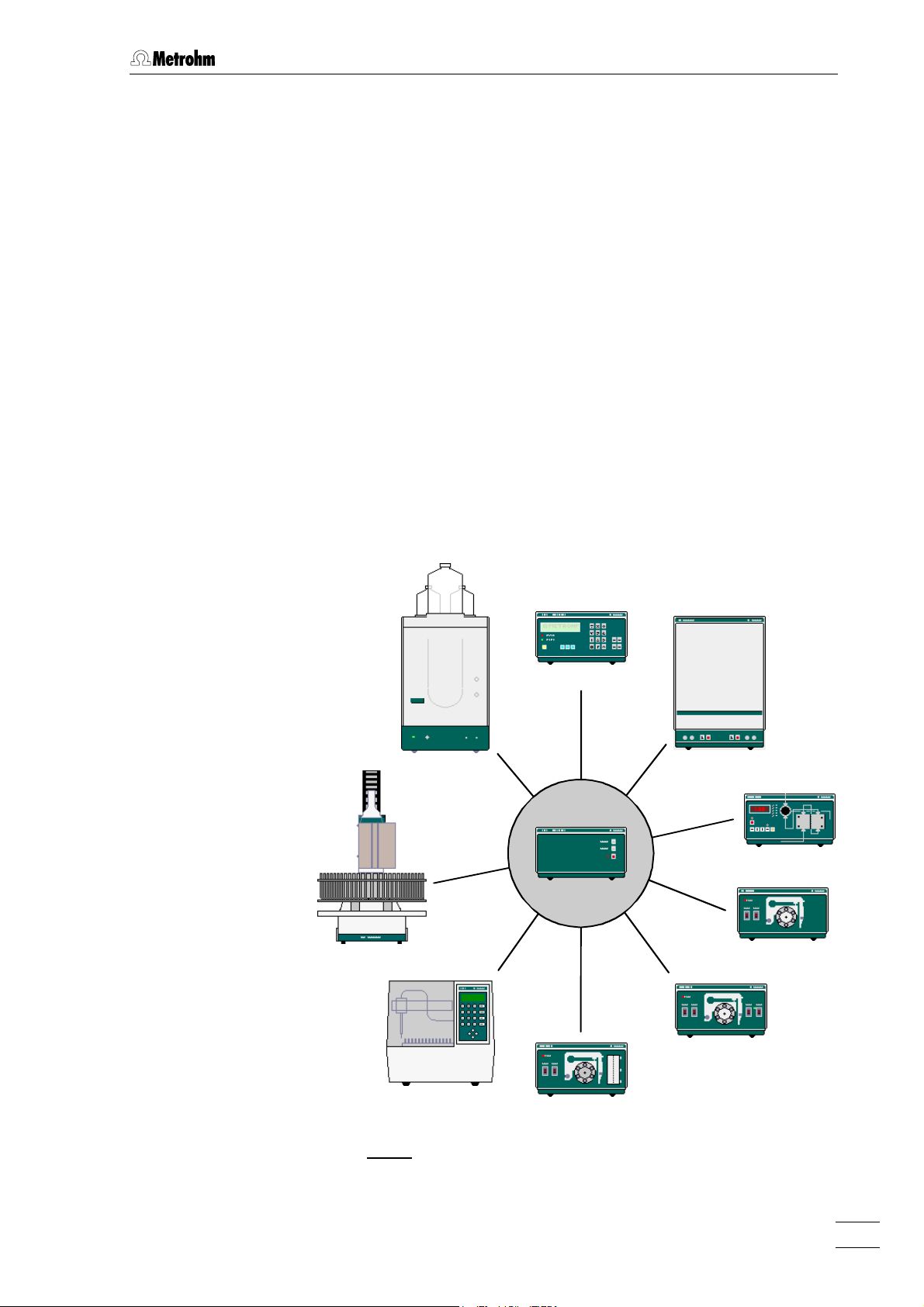
Fig. 1 shows an overview of all the Metrohm instruments which can be
connected to the 762 IC Interface and are described in these
‘Instructions for Use’. It is also possible to connect Bischoff instruments; please refer to the «IC Net» on-line program help as well as the
relevant Bischoff instruction manuals.
1.1 Instrument description
761 Compact IC
766 IC Sample Processor
750 Autosampler
732 IC Detector
733 IC Separation Center
709 IC Pump
762 IC Interface
752 Pump Unit
753 Suppressor Module
754 Dialysis Unit
Fig. 1: Connection possibilities at 762 IC Interface
762 IC Interface 1
Page 6
1 Introduction
1.2 Parts and controls
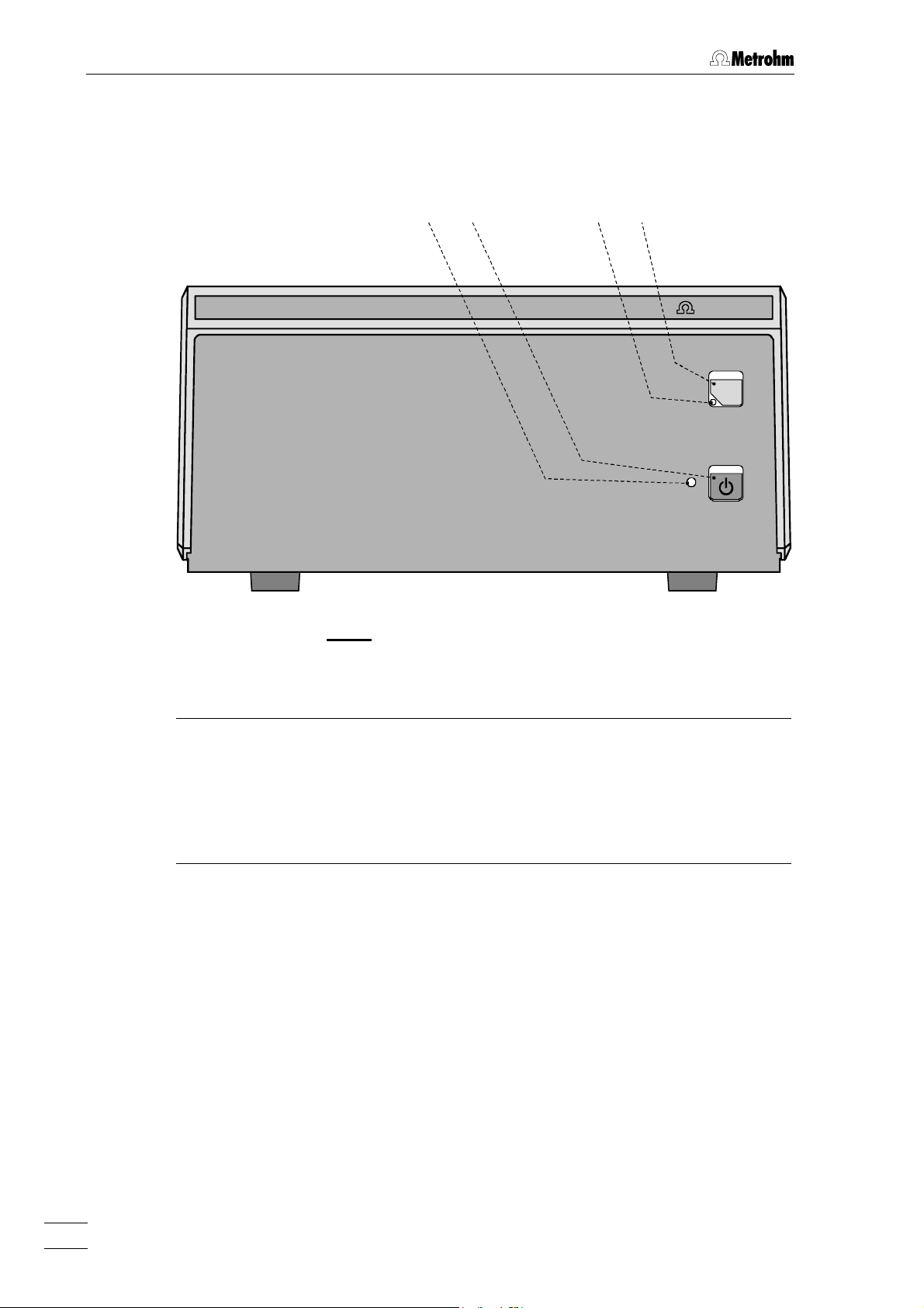
1.2.1 2.762.0010 IC Interface
762 IC Interface
1122
Fig. 2: Front of 2.762.0010 IC Interface
3344
SYSTEM 1
MetrohmMetrohm
RUN/
STOP
11 Mains switch
For switching the instrument
on/off
22 Mains pilot lamp
Lights up when instrument is
switched on
33 Run/Stop key for System 1
RUN: Manual start of a determi-
nation (external start)
STOP: Manual stop of a determi-
nation or data acquisition
(if defined in «IC Net»)
44 Status display for System 1
LED dark: No system loaded
LED lit up: Instrument ready
(waiting for external
start)
LED flashes: Determination run-
ning
762 IC Interface2
Page 7
1.2 Parts and controls
Type 1.762.0020 Nr.
100 - 240 V
f = 50-60 Hz
P = 7 W
S
99
Made by Metrohm Herisau Switzerland
System 1
1 2 3 4 5 6 7
Channels 1/2
Dev. 1/5 Dev. 2/6 Dev. 3/7 Dev. 4/8
101012121313
PC
Events
Run
Start
Com
77 88 1111
1414
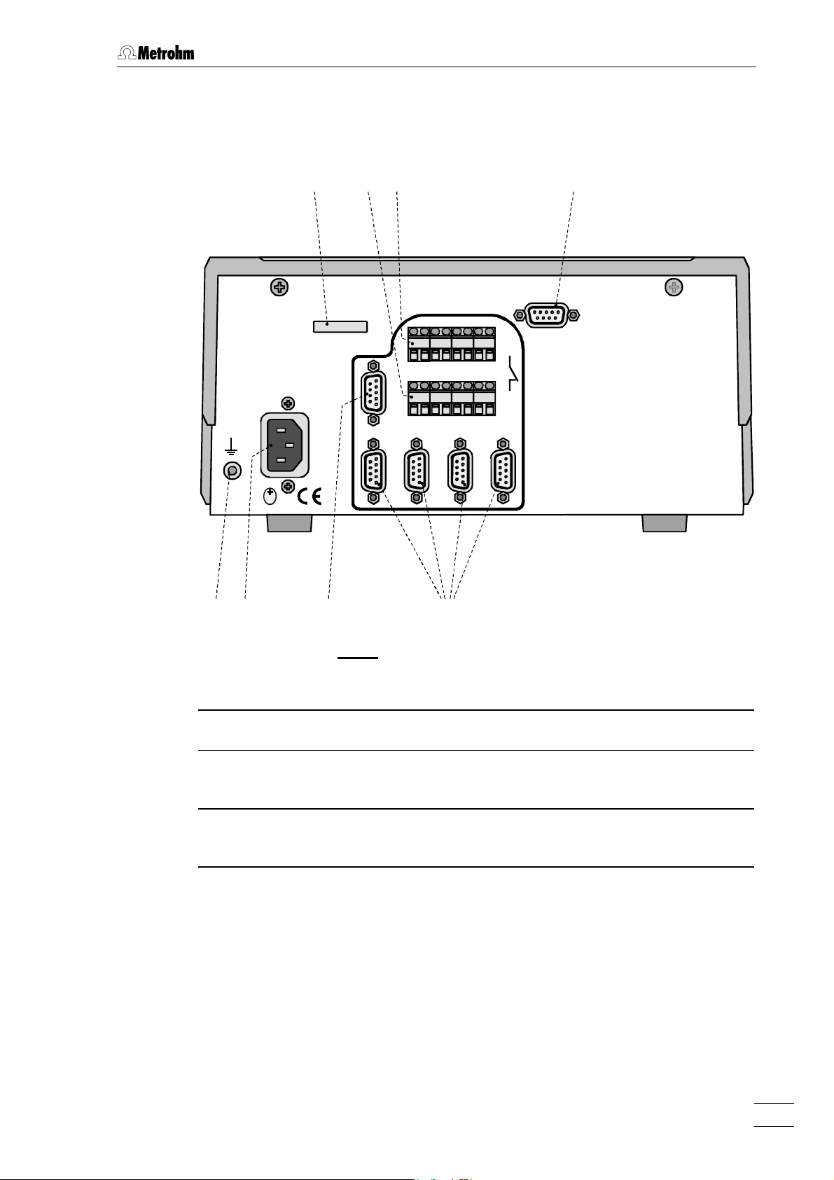
Fig. 3: Rear of 2.762.0010 IC Interface
77 Earthing socket 1111 Analog signal connection
88 Mains connection plug
Mains connection see section 2.2
1212 Remote input/output lines
connection (RUN)
99 Serial number 1313 Remote input/output lines
connection (COM)
1010 PC connection
1414 RS232 interfaces
RS232 interface
762 IC Interface 3
Page 8
1 Introduction
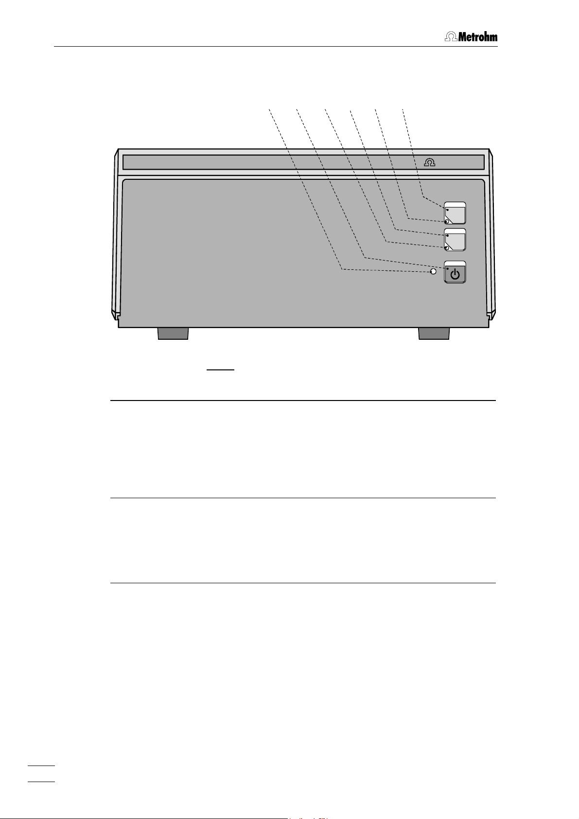
1.2.2 2.762.0020 IC Interface
762 IC Interface
1122
5566
Fig. 4: Front of 2.762.0020 IC Interface
3344
SYSTEM 1
SYSTEM 2
MetrohmMetrohm
RUN/
STOP
RUN
RUN/
STOP
STOP
11 Mains switch
For switching the instrument
on/off
22 Mains pilot lamp
Lights up when instrument is
switched on
33 Run/Stop key for System 1
RUN: Manual start of a determi-
nation (external start)
STOP: Manual stop of a determi-
nation or data acquisition
(if defined in «IC Net»)
44 Status display for System 1
LED dark: No system loaded
LED lit up: Instrument ready
(waiting for external
start)
LED flashes: Determination run-
ning
55 Run/Stop key for System 2
RUN: Manual start of a determi-
nation (external start)
STOP: Manual stop of a determi-
nation or data acquisition
(if defined in «IC Net»)
66 Status display for System 2
LED dark: No system loaded
LED lit up: Instrument ready
(waiting for external
start)
LED flashes: Determination run-
ning
762 IC Interface4
Page 9
1.2 Parts and controls
99
Made by Metrohm Herisau Switzerland
System 1
Type 1.762.0020 Nr.
100 - 240 V
f = 50-60 Hz
P = 7 W
Dev. 1/5 Dev. 2/6 Dev. 3/7 Dev. 4/8
S
77 88 1111 1818
Events
1 2 3 4 5 6 7
Com
Channels 1/2
1414
101012121313
PC
System 2
Events
Channels 3/4
1515
1616 1717
RunRun
StartStart 1 2 3 4 5 6 7
Com
Dev. 4/8Dev. 3/7Dev. 2/6Dev. 1/5
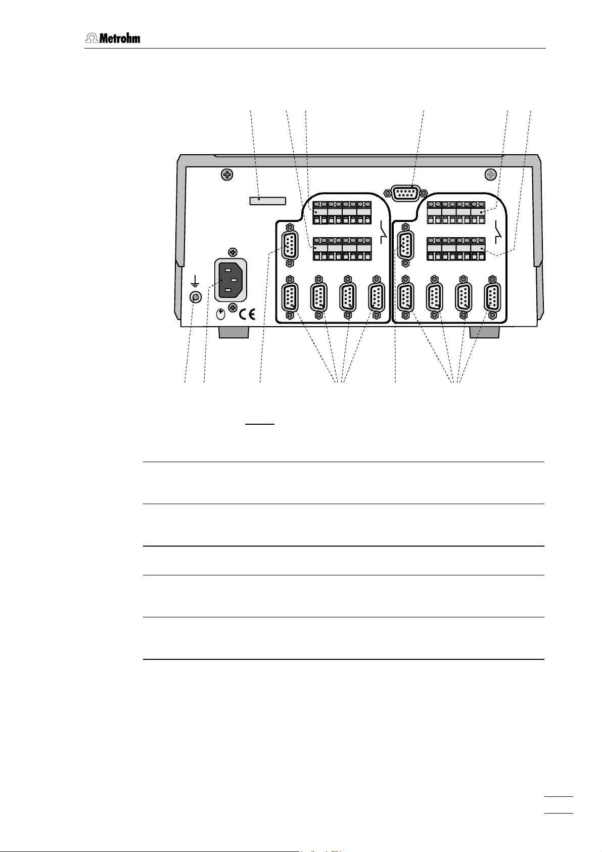
Fig. 5: Rear of 2.762.0020 IC Interface
77 Earthing socket 1313 Remote input/output lines
connection (COM)
88 Mains connection plug
1414 RS232 interfaces
Mains connection see section 2.2
99 Serial number 1515 Analog signal connection
1010 PC connection
RS232 interface
1616 Remote input/output lines
connection (RUN)
1111 Analog signal connection 1717 Remote input/output lines
connection (COM)
1212 Remote input/output lines
1818 RS232 interfaces
connection (RUN)
762 IC Interface 5
Page 10
1 Introduction
1.3 Information on the Instructions for Use
Please read through these Instructions for Use carefully before you put
the 762 IC Interface into operation. The Instructions for Use contain
information and warnings to which the user must pay attention in order
to assure safe operation of the instrument.
1.3.1 Organization
These 8.762.1003 Instructions for Use for the 762 IC Interface provide a comprehensive overview of the installation, startup procedure,
operation and technical specifications of this instrument. The Instructions for Use are organized as follows:
Section 1 Introduction
General description of instrument, parts and controls
and safety notes
Section 2 Installation
Mains connection, connection to PC,
connection of external instruments
Section 3 Operation
Manual operation and operation via «IC Net»
Section 4 Operation
Technical data, standard equipment, options, warranty,
declarations of conformity, index
To find the required information on the instruments you will find it an
advantage to use either the Table of contents or the Index at the
back.
762 IC Interface6
Page 11

1.3.2 Notation and pictograms
The following notations and pictograms (symbols) are used in these Instructions for Use:
Range Menu item, parameter or entry
SYSTEM STATE Program window
<OK> Button
[ RUN/STOP ] Switch or key
1.3 Information on the Instructions for Use
value
in «IC Net» program
in «IC Net» program
in «IC Net» program
1515 Part or control of 762
Hazard
This symbol draws attention to a
possible danger to life or of injury if
the associated directions are not
followed correctly.
Warning
This symbol draws attention to
possible damage to instruments or
instrument parts if the associated
directions are not followed correctly.
Caution
This symbol marks important information. First read the associated
directions before you continue.
Comment
This symbol marks additional information and tips.
762 IC Interface 7
Page 12
1 Introduction
1.4 Safety notes
While electrical safety in the handling of the 762 IC Interface is assured
in the context of the specifications IEC 1010-1 (protection class 1, degree of protection IP40), the following points should be noted:
• Mains connection
The mains connection must be effected in accordance with the
instructions in section 2.2.
• Opening the instrument
Inside the instrument there are no parts which must be set or adjusted
by the user.
If the 762 IC Interface is connected to the power supply, the instrument must not be opened nor must parts be removed from it, otherwise there is a danger of coming into contact with components which
are live. Hence, always disconnect the instrument from all voltage
sources before you open it and ensure that the mains cable is
disconnected from mains connection 8 8 !
• Protection against static charges
Electronic components are sensitive to static charging and can be
destroyed by discharges. Before you touch any of the components
inside the 762 IC Interface, you should earth yourself and any tools
you are using by touching an earthed object (e.g. housing of the
instrument or a radiator) to eliminate any static charges which exist.
762 IC Interface8
Page 13

2 Installation
2.1 Setting up the instrument
2.1.1 Packaging
The 762 IC Interface is supplied together with the separately packed
accessories in special packagings containing shock-absorbing foam
linings designed to provide excellent protection. The instrument itself is
packed in an evacuated polyethylene bag to prevent the ingress of
dust. Please store all these special packagings as only they assure
transport of the instrument free from damage.
2.1.2 Check
2.1 Setting up the instrument
After receipt, immediately check whether the shipment is complete and
has arrived without damage (compare with delivery note and list of
accessories in section 4.2). In the case of transport damage, see
instructions in section 4.4.1 "Warranty".
2.1.3 Location
Position the instrument in the laboratory at a location convenient for operation, free from vibrations and protected against a corrosive atmosphere and contamination by chemicals.
2.1.4 Arrangement of the instruments
The 762 IC Interface can be piled up together with other IC instruments
(e.g. 732, 733, 709).
762 IC Interface 9
Page 14
2 Installation
2.2 Mains connection
2.2.1 Mains voltage and fuses
The 762 Interface has a power supply which automatically adjusts itself
to the existing mains voltage (100…240 V) and frequency (50…60 Hz).
It is equipped with an electronic overload protection device and also
has two fuses; however, these should only be exchanged by Metrohm
service technicians.
2.2.2 Mains cable
The instrument is supplied with one of three mains cables
• 6.2122.020 with plug SEV 12 (Switzerland, …)
• 6.2122.040 with plug CEE(7), VII (Germany, …)
• 6.2133.070 with plug NEMA 5-15 (USA, …)
which are three-cored and fitted with a plug with an earthing pin. If a
different plug has to be fitted, the yellow/green lead (IEC standard)
must be connected to the earthing socket 77 (protection class 1).
Any break in the earthing inside or outside the instrument can make it
a hazard!
Plug the mains cable into mains connection plug 88 at the 762 IC Inter-
face (see Fig. 3 and Fig. 5).
2.2.3 Switching the instrument on/off
The 762 IC Interface is switched on and off using mains switch 11 (see
Fig. 2 and Fig. 4). When the instrument is switched on the mains pilot
lamp 22 lights up.
762 IC Interface10
Page 15

2.3 Connection to the PC
2.3.1 Connecting cable
Always switch off 762 IC Interface and PC before you connect the two
instruments with the 6.2134.100 Cable.
Connect the PC connection 1010 at the 762 IC Interface to one of the se-
rial COM ports at the PC using the 6.2134.100 Cable (9 pin/9 pin). If
only a 25-pin COM interface is available on the PC then the 6.2125.110
Adapter cable or a commercially available adapter must be used.
6.2134.100
2.3 Connection to the PC
762
Fig. 6: Connection of 762 IC Interface to PC
2.3.2 Software installation
The PC program «IC Net 2.0» is required for the operation of the 762
IC Interface; this is contained on the 6.6034.003 CD included in the accessories. This program runs under Windows 95, Windows 98 and
Windows NT operating systems and is installed according to section
1.4.2 of the «IC Net» Instructions for Use.
762 IC Interface 11
Page 16

2 Installation
2.4 Connection of external instruments
2.4.1 General information
Before an external instrument is connected to the 762 IC Interface, the
762 IC Interface must always be switched off using mains switch 11 !
Each system of the two versions of the 762 IC Interface has four RS232
interfaces 1414 or 1818 for connection of a maximum of 8 external instru-
ments, an 1111 or 1515 interface for analog signals from a maximum of 2
detectors and 8 remote output lines 1212/1313 or 1616/1717 for controlling ex-
ternal instruments by making contacts or impulses (see Fig. 2 and
Fig. 4). Information about the technical data of these interfaces is given
in section 4.1.
For installation and startup of external instruments proceed as follows:
Switch off all instruments
1
• Switch off 762 IC Interface and all external instruments using
the mains switch.
Connect instruments
2
• Connect the instruments to the 762 IC Interface according to
the connection diagrams shown in sections 2.4.2 to 2.4.9 by
using the cables named in the diagrams. Other instrument
combinations can be set up by using these examples as a
guide.
Switch on all instruments
3
• Switch on 762 IC Interface and all external instruments using
the mains switch.
Instrument settings
4
Operation with the 762 IC Interface requires that the following
settings must be made:
• 732 IC Detector:
>CONFIG/RS settings
handshake: SWchar
>CONFIG/RS settings
RS control: on
• 709 IC Pump:
Switch on external control of the 709 IC Pump using the
[ EXT. ] key.
• 752 Pump Unit, 753 Suppressor Module,
754 Dialysis Unit:
Switch on external control via remote interface using the
[ Remote ] switch.
762 IC Interface12
Page 17

2.4 Connection of external instruments
PC
6.2134.100
6.2128.130
6.2115.070
6.2134.090
6.2125.090
(732)
• 750 Autosampler:
Always switch on the 762 IC Interface first and then the 750
Autosampler.
• 766 IC Sample Processor:
>RS232 settings
handshake: SWchar
>RS232 settings
RS control: on
Create new system in «IC Net»
5
• Start the «IC Net» program.
• Create a new system file with the selected instruments
(details see IC Net Instructions for Use).
2.4.2 732 IC Detector, 733 IC Separation Center, 709 IC Pump
Example
Analysis of anions or cations on a modular system with electronic suppression.
Instruments
• 2.762.0010 IC Interface for 1 system
• 2.732.0010 IC Detector with standard detector block
• 2.733.0010 IC Separation Center with 1 injector
• 2.709.0010 IC Pump
Interconnection
732
733
709762
Fig. 7: Connection of 732, 733 and 709
762 IC Interface 13
Page 18

2 Installation
2.4.3 752 Pump Unit
Example
Analysis of anions or cations on a modular system with chemical suppression.
Instruments
• 2.762.0010 IC Interface for 1 system
• 2.732.0110 IC Detector with metal-free detector block
• 2.733.0130 IC Separation Center with 1 injector
• 2.709.0110 IC Pump, metal-free
• 2.752.0010 Pump Unit
Interconnection
and suppressor module, metal-free
732
6.2128.130
733
6.2125.090
(732)
6.2115.070
6.2134.100
PC
6.2134.090
709762
6.2128.180
752
Fig. 8: Connection of 732, 733, 709 and 752
762 IC Interface14
Page 19

2.4.4 753 Suppressor Module
Example
Simultaneous analysis of cations and anions on a modular system with
two independent detectors.
Instruments
• 2.762.0020 IC Interface for 2 systems
• 2.732.0110 IC Detector with metal-free detector block for
• 2.732.0110 IC Detector 732 with metal-free detector block for
• 2.733.0120 IC Separation Center with 2 injectors, metal-free
• 2.709.0110 IC Pump, metal-free, for System 1 (cations)
• 2.709.0110 IC Pump, metal-free, for System 2 (anions)
• 2.753.0010 Suppressor Module, for System 2 (anions)
Interconnection
2.4 Connection of external instruments
System 1 (cations)
System 2 (anions)
PC
6.2134.100
6.2128.130
6.2128.130
6.2134.090
732-1
733
6.2115.070
709-1762
6.2115.070
6.2128.180
6.2128.180
6.2125.090
6.2134.090
(732)
732-2
709-2
753
6.2125.090
(732)
Fig. 9: Connection of 2××732, 733, 2××709 and 753
762 IC Interface 15
Page 20

2 Installation
2.4.5 754 Dialysis Unit
Example
Analysis of anions on a modular system with chemical suppression after preceding sample dialysis.
Instruments
• 2.762.0010 IC Interface for 1 system
• 2.732.0110 IC Detector 732 with metal-free detector block
• 2.733.0120 IC Separation Center with 2 injectors, metal-free
• 2.709.0110 IC Pump, metal-free
• 2.753.0010 Suppressor Module
• 2.754.0010 Dialysis Unit
Interconnection
6.2128.130
732
733
6.2125.090
(732)
754
753
6.2134.100
6.2115.070
PC
709762
6.2134.090
6.2128.180
6.2128.180
6.2128.180
Fig. 10: Connection of 732, 733, 709, 752 and 754
762 IC Interface16
Page 21

2.4.6 750 Autosampler
Example
Automatic analysis of anions or cations on a modular system with electronic suppression using the 750 Autosampler.
Instruments
• 2.762.0010 IC Interface for 1 system
• 2.732.0010 IC Detector with standard detector block
• 2.733.0010 IC Separation Center with 1 injector
• 2.709.0010 IC Pump
• 2.750.0010 Autosampler
Interconnection
6.2128.130
2.4 Connection of external instruments
732
733
6.2125.090
(732)
6.2115.070
750
6.2128.100
6.2134.100
PC
709762
6.2134.090
6.2134.000
Fig. 11: Connection of 732, 733, 709 and 750
LOAD NO
LOAD COM
INJECT NO
INJECT COM
762 IC Interface 17
Page 22

2 Installation
2.4.7 766 IC Sample Processor
Example
Automatic analysis of anions or cations on a modular system with electronic suppression using the 766 IC Sample Processor.
Instruments
• 2.762.0010 IC Interface for 1 system
• 2.732.0010 IC Detector with standard detector block
• 2.733.0010 IC Separation Center with 1 injector
• 2.709.0010 IC Pump
• 2.766.0010 IC Sample Processor
Interconnection
6.2128.130
732
733
6.2125.090
(732)
6.2115.070
6.2134.100
PC
709762
766
6.2134.090
6.2134.080
6.2141.110
Fig. 12: Connection of 732, 733, 709 and 766
762 IC Interface18
Page 23

2.4.8 791 VA Detector
Example
Analysis of anions or cations on a modular system with electronic suppression with simultaneous conductometric and electrochemical detection.
Instruments
• 2.762.0010 IC Interface for 1 system
• 2.732.0010 IC Detector with standard detector block
• 2.733.0010 IC Separation Center with 1 injector
• 2.709.0010 IC Pump
• 2.791.0020 VA Detector
Interconnection
2.4 Connection of external instruments
732
733
6.2125.090
(732)
6.2115.070
6.2134.100
PC
6.2134.090
709762
6.2128.130
791
Fig. 13: Connection of 732, 733, 709 and 791
762 IC Interface 19
Page 24

2 Installation
2.4.9 761 Compact IC
Example
Connection of a modular system and a 761 Compact IC to a 762 IC Interface (if not enough COM ports are available at the PC).
Instruments
• 2.762.0010 IC Interface for 1 system
• 2.732.0010 IC Detector with standard detector block
• 2.733.0010 IC Separation Center with 1 injector
• 2.709.0010 IC Pump
• 2.761.0020 Compact IC with suppressor module
Interconnection
732
6.2128.130
6.2115.070
6.2134.100
733
PC
709762
6.2134.090
6.2134.100
6.2125.090
(732)
761
Fig. 14: Connection of 732, 733, 709 and 761
762 IC Interface20
Page 25

3 Operation
3.1 Manual operation
Switch instrument on/off
The 762 IC Interface 762 is switched on and off using mains
switch 11 on the front of the instrument (see Fig. 2 and Fig. 4).
After the instrument has been switched on the mains pilot lamp 22
lights up to show that the instrument is ready for use.
Start/stop determination
3.1 Manual operation
RUN/
STOP
Determination on System 1 or System 2 can be started or
stopped manually using the key 33 or key 55.
RUN: Manual start of a determination (Start determination).
STOP: Manual stop of a determination or data acquisition (Stop
determination or Stop data acquisition).
This function is only available if the Second press of
Run/Stop button means 'stop' when measuring option is en-
abled in the 762 IC Interface window.
The status display 4 4 or 66 within the RUN/STOP key 33 or 55 have
the following meaning:
LED dark: No system loaded
LED lit up: Instrument ready (waiting for external start)
LED flashes: Determination running
762 IC Interface 21
Page 26

3 Operation
3.2 Operation via «IC Net»
This section describes only the most important points concerning the
operation of the 762 IC Interface. For further details please refer to the
«IC Net» Instructions for Use and to the on-line help in the PC program.
3.2.1 Settings in the "762 IC Interface" window
By clicking the 762 icon in the toolbar with the left mouse button or by
clicking this icon with the right mouse button and selecting the Open
menu item the 762 IC Interface window for parameter settings is opened.
It consists of three tabs Init, RS settings, and Links.
Init
The Init tab of the 762 IC Interface window contains data acquisition parameters for the 762 IC Interface.
Label Optional label to name the interface with
maximum 8 characters.
ROM version Instrument program version number.
Measuring per second Number of data points measured per s.
Entry range: 10, 20, 30, 50, 60 points/s
Range Range for AD converter .
Example: converts ± 2500 mV to 224 bits
Entry range: 2500, 1250, 625, 312.5, 156.25, 78.125,
39.062 mV
762 IC Interface22
Page 27
3.2 Operation via «IC Net»
Second press on RUN/STOP means 'stop' when measuring
If this option is enabled, the running data acquisition will be stopped if key 33 or key 55
[ RUN/STOP ] on the 762 IC Interface front
panel is pressed. This is equal to Stop determi-
nation.
If this option is disabled, the running data acquisition will not be stopped if key 33 or key 55
[ RUN/STOP ] on the 762 IC Interface front
panel is pressed.
<ASK> Read current parameters from 762 IC Interface.
<SET> Send current parameters to 762 IC Interface.
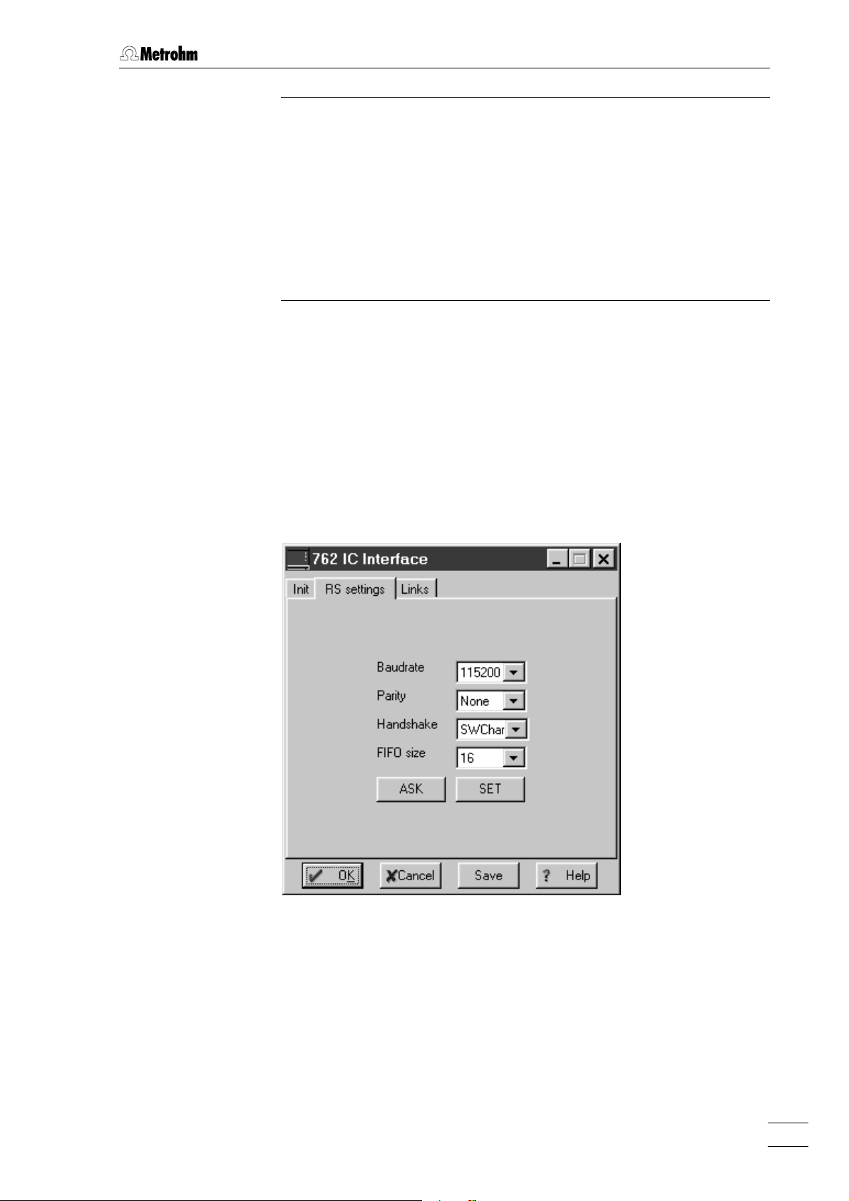
RS settings
The RS settings tab of the 762 IC Interface window contains RS232 parameters for the 762 IC Interface.
Baud Rate Baud rate of the device.
Selection: 1200...115200
Default value: 115200
Parity Parity check.
Selection: None, Even, Odd
Default value: None
Handshake Enable/disable software handshake mode.
Selection: Swchar, none
Default value: SWchar
762 IC Interface 23
Page 28

3 Operation
FIFO size Intermediate memory in byte.
Selection: 1...16
Default value: 16
<ASK> Read current parameters from 762 IC Interface.
<SET> Send current parameters to 762 IC Interface.
Links
The Links tab of the 762 IC Interface is used for RS232 interface (COM
port) selection and settings.
Alias Name of the instrument.
COM # If this entry is clicked with the right mouse but-
ton, the following menu appears:
Put on desktop Possibility for setting RS232 interface parame-
ters (details see on-line help).
Change Possibility for changing the RS232 interface.
The following window is opened, where the
COM port can be changed by clicking on the
desired entry.
762 IC Interface24
Page 29

3.2.2 Event output lines
The 762 System [#] window with programs and settings for the seven
event output lines is opened by selecting the Open menu item with the
right mouse button or by double-clicking the 762 icon added to the
SYSTEM window. It consists of the tabs Program and Events setup.
Time program
On the Program tab of the 762 System [#] window a user-defined time
program for the event output lines of the 762 IC Interface can be entered. This program is started automatically as defined in the Start mode
window either at the moment the determination is started (Start with de-
termination) or at the moment the sample is injected (Start with inject).
3.2 Operation via «IC Net»
The Program tab contains the two following subpages:
Program Main time program with all program steps.
Events configuration Possibility for creation of user-defined remote
commands.
762 IC Interface 25
Page 30

3 Operation
Program
On the Program subpage, program steps including time, program instruction and parameter can be entered.
First column Time at which program instruction is applied.
Entry range: 0.0 ... 999.9 min
If no time is entered, the program instruction is
applied together with the last instruction with
time entry.
Second column Program instruction (see below).
In addition to these predefined instructions,
user-defined remote commands can be entered if activated on the Events configuration tab.
Third column Parameter for program instruction (see below).
ENABLED Enable program start (a disabled program is
not started).
<Add> Add new program instruction.
<Delete> Delete selected program instruction.
<Verify> Test the time program (error messages are dis-
played if program is wrong).
List of program instructions
The following program instructions can be added to the time program
on the Program subpage:
Instruction Entry Meaning
Events 0, 1, p, * Set event output lines 1...7 to the desired
values. For entry of the first value, enter 1,
0, p or *. For entry of the other values, move
the cursor in front of the value to be
changed and enter 1, 0, p or *.
Program END, RESET The END flag can be used to end a
program, especially if the program time
should be longer than the chromatogram
duration. Additional steps after this flag are
not allowed. The RESET flag is used to
reset the parameters to the system startup
values.
762 IC Interface26
Page 31

3.2 Operation via «IC Net»
Events configuration
On the Events configuration subtab user-defined event commands can
be defined, which can be inserted into a time program after being activated with <Activate>.
Name (1st column) User-definable name of the event command
(e.g. Start_766).
Event command (2nd column)
Setting the event output lines 1…7.
Selection:
0 (line off, inactive, open)
1 (line on, active, 0 V)
p (pulse, pulse length 150 ms)
* (leave line in current status)
For entry of the first value, enter 1, 0, p or *. For
entry of the other values, move the cursor in
front of the value to be changed and enter 1, 0,
p or *.
<Add> Add new remote command.
<Delete> Delete selected remote command.
<Activate> Activate the defined remote commands for in-
sertion into the time program.
762 IC Interface 27
Page 32

3 Operation
Events setup
The Events setup tab of the 762 System [#] window contains the startup
values for the seven event output lines of system 1 or system 2 of the
762 IC Interface. These startup values are sent each time the system is
connected or a determination is started.
Each event output line can be set to the following values:
0 Line off, inactive (open)
1 Line on, active (0 V)
For technical data to the event output lines see section 4.1.
762 IC Interface28
Page 33

4 Appendix
4.1 Technical data
Mains connection
Voltage 100...240 V
Frequency 50...60 Hz
Power consumption 7 VA
Fuse 2 × 1 ATH (to be replaced by Metrohm Service
PC interface (RS232)
Connector Dsub connector 9 pin (male)
4.1 Technical data
only using the same type)
Additional electronic overload protection
1 5
96
Baud rate 1'200…115'200
Data bits 8
Stop bits 1
Handshake Xon/Xoff, none
Parity none, even, odd
FIFO 0…16 Bytes
Pin assignment
RS232 interfaces
Connector Dsub connector 9 pin (male)
Pin 1,4,6: internally connected
Pin 2: RxD (Received Data)
Pin 3: TxD (Transmitted Data)
Pin 5: GND (Signal Ground)
Pin 7,8: internally connected
1 5
96
Baud rate 1'200…115'200 (for Dev. 8 1'200…19'200)
Data bits 7, 8
Stop bits 1, 2
Handshake Xon/Xoff, none
Parity none, even, odd
762 IC Interface 29
Page 34

4 Appendix
FIFO 0…16 Bytes (for Dev. 8 not available)
Pin assignment
Remote interface (Events)
Output lines
Input lines
Pin 2: RxD (Received Data) for Dev. 1…4
Pin 3: TxD (Transmitted Data) for Dev. 1…4
Pin 5: GND (Signal Ground) for Dev. 1…4
Pin 7: TxD (Transmitted Data) for Dev. 5…8
Pin 8: RxD (Received Data) for Dev. 5…8
Pin 9: GND (Signal Ground) for Dev. 5…8
7 potential-free relay contacts per system for
controlling external instruments.
RUN
Maximum contact load:
30 V / 1 A DC
COM
1 digital input per system for external method
start.
+5V
470k
47k
Maximum load for external contact:
approx. 0.1 mA at max. cut-off voltage of approx.
5 V
Analog signal interface
Function
2 potential-free analog signal inputs per system.
Connector Dsub connector 9 pin (female)
15
69
Input voltage range ± 2.5 V
Input amplification 1, 2, 4, 8, 16, 32, 64 (selectable)
Sampling rate 10, 20, 30, 50, 60 measuring points/s
RUN
Ext. Start
COM
Resolution 24 bit (1 LSP = 0.298 µV at amplification 1)
Noise < 20 µVpp
< 3 µVrms (at 0 V input voltage, amplification 1
and sampling rate 10 Hz)
762 IC Interface30
Page 35

Zero error ± 2.5 mV
4.1 Technical data
Pin assignment
Pin 1,4,5,8,9: GND (ground, connected to
housing)
Pin 2: Analog 1+
Pin 3: Analog 1–
Pin 6: Analog 2+
Pin 7: Analog 2–
Safety specifications
Construction/testing According to IEC 1010 / EN 61010 / UL 3101-1,
protection class 1, degree of protection IP40
Safety directions The Instructions for Use include information and
warnings which must be heeded by the user to
assure safe operation of the instrument.
Electromagnetic compatibility (EMC)
Emitted interference Standards met:
EN55011 (level B), EN55022 (level B),
EN 50081-1/2, EN61000-3-2
Immunity to interference Standards met:
IEC61000-4-2/EN61000-4-2 (level 3),
IEC61000-4-3/EN61000-4-3 (level 3),
IEC61000-4-4/EN61000-4-4 (level 4),
IEC61000-4-5/EN61000-4-5 (level 2/3),
IEC61000-4-6/EN61000-4-6 (level 3),
IEC61000-4-11/EN61000-4-11,
IEC61000-4-14/EN61000-4-14 (level 3),
EN50082-2, NAMUR
Ambient temperature
Nominal operating range +5…+45°C
(at 20…80 % atmospheric humidity)
Storage, transport –40…+70°C
Housing
Material of cover Polyurethane rigid foam (PUR) with fire protection
for fire class UL94VO, CFC-free
Material of base Steel, enameled
Dimensions
Width 255 mm
Height 128 mm
Depth 340 mm
Weight (with accessories) 2.762.0010: 4.3 kg
2.762.0020: 4.9 kg
762 IC Interface 31
Page 36

4 Appendix
4.2 Scope of delivery
Subject to changes !
All dimensions are given in mm.
The 762 IC Interface is available in the two following versions:
• 2.762.0010 IC Interface for 1 IC system with 2 channels
• 2.762.0020 IC Interface for 2 IC systems with 4 channels
The two instruments include the following parts:
Quant. Order No. Description
2.762.0010
2.762.0020
1 2 6.2115.070 Connection cable
Connection cable 762 IC Interface –
733 IC Separation Center
1 2 6.2128.130 Connection cable
Connection cable 762 IC Interface –
analog output (channel 1/2 or 3/4)
1 2 6.2134.090 RS232 connection cable
Connection cable 762 IC Interface –
2 external devices (709, 732, 766, etc.)
1 1 6.2134.100 RS232 connection cable
Connection cable 762 IC Interface – PC
1 1 6.6034.003 Software CD «IC Net 2.0»
1 1 6.2122.0X0 Mains cable
according to customer's specification:
Cable socket Cable plug
Type IEC 320/C 13 Type SEV 12 (CH…) ...............................6.2122.020
Type IEC 320/C 13 Type CEE (7), VII (D…) ...........................6.2122.040
Type CEE (22), V Type NEMA 5-15 (USA…).......................6.2122.070
1 1 8.762.1003 Instructions for Use (English)
for 762 IC Interface
1 1 8.110.8193 Instructions for Use (English)
for «IC Net 2.0» PC program
1 1 8.110.8213 Instructions for Use (English)
for «Autodatabase 1.0» PC program
1 1 8.110.8207 Registration card
762 IC Interface32
Page 37

4.3 Optional accessories
6.2128.180 Remote connection cable
Connection cable 762 IC Interface –
752, 753, 754
6.2134.000 RS232 connection cable
Connection cable 762 IC Interface –
750 Autosampler
6.2134.080 RS232 connection cable
Connection cable 762 IC Interface –
1 external device (709, 732, 766, etc.)
6.2141.110 Connection cable
Connection cable 762 IC Interface –
732 IC Detector– 766 IC Sample Processor (accessory part of 766)
4.3 Optional accessories
762 IC Interface 33
Page 38

4 Appendix
4.4 Warranty and conformity
4.4.1 Warranty
The warranty on our products is limited to defects that are traceable to
material, construction or manufacturing error which occur within 12
months from the day of delivery. In this case, the defects will be rectified in our workshops free of charge. Transport costs are to be paid by
the customer.
For day and night operation, the warranty is limited to 6 months.
Glass breakage in the case of electrodes or other parts is not covered
by the warranty. Checks which are not a result of material or manufacturing faults are also charged during the warranty period. For parts of
outside manufacture insofar as these constitute an appreciable part of
our instrument, the warranty stipulations of the manufacturer in question
apply.
With the regard to the guarantee of accuracy, the technical specifications in the instruction manual are authoritative.
Concerning defects in material, construction or design as well as the
absence of guaranteed features, the orderer has no rights or claims except those mentioned above.
If damage of the packaging is evident on receipt of a consignment or if
the goods show signs of transport damage after unpacking, the carrier
must be informed immediately and a written damage report demanded.
lack of an official damage report releases Metrohm from any liability to
pay compensation.
If any instruments and parts have to be returned, the original packaging
should be used if at all possible. This applies above all to instruments,
electrodes, burette cylinders and PTFE pistons. Before embedment in
wood shavings or similar material, the parts must be packed in a dustproof package (for instruments, use of a plastic bag is imperative). If
open assemblies are enclosed in the scope of delivery that are sensitive to electromagnetic voltages (e.g. data interfaces etc.) these must
be returned in the associated original protective packaging (e.g. conductive protective bag). (Exception: assemblies with built-in voltage
source belong in a non-conductive protective packaging).
No warranty responsibility whatsoever will be accepted by Metrohm for
damage which arises as a result of non-compliance with these instructions.
762 IC Interface34
Page 39

4.4.2 EU Declaration of conformity
EU Declaration of Conformity
The Metrohm AG company, Herisau, Switzerland hereby certifies that the instrument:
762 IC Interface
meets the requirements of EC Directives 89/336/EWG and 73/23/EWG.
4.4 Warranty and conformity
Source of the specifications:
EN 50081-1/2 Electromagnetic compatibility, basic specification
Emitted Interference
EN 50082-2 Electromagnetic compatibility, basic specification
Interference Immunity
EN 61010 Safety requirements for electrical laboratory measurement
and control equipment
Description of the instrument:
PC controlled chromatography data system for remote control of IC instruments and for automatic evaluation of chromatograms
Herisau, April 21, 1999
Dr. J. Frank Ch. Buchmann
Development Manager Production and
Quality Assurance Manager
762 IC Interface 35
Page 40

4 Appendix
4.4.3 Certificate of conformity and system validation
Certificate of Conformity and System Validation
This is to certify the conformity to the standard specifications for electrical appliances and accessories, as well as to the standard specifications for security and
to system validation issued by the manufacturing company.
Name of commodity: 762 IC Interface
Name of manufacturer: Metrohm Ltd., Herisau, Switzerland
Technical specifications: Voltages: 100-240 V
Frequency: 50-60 Hz
This Metrohm instrument has been built and has undergone final type testing
according to the standards:
EN55011 (level B), EN55022 (level B), EN 50081-1/2, EN61000-3-2,
IEC61000-4-2/EN61000-4-2 (level 3), IEC61000-4-3/EN61000-4-3 (level 3),
IEC61000-4-4/EN61000-4-4 (level 4), IEC61000-4-5/EN61000-4-5 (level 2/3),
IEC61000-4-6/EN61000-4-6 (level 3), IEC61000-4-11/EN61000-4-11,
IEC61000-4-14/EN61000-4-14 (level 3), EN50082-2, NAMUR
— Electromagnetic compatibility
IEC1010, EN61010, UL3101-1 — Security specifications
It has also been certified by the Swiss Electrotechnical Association (SEV), which
is member of the International Certification Body (CB/IEC).
The technical specifications are documented in the instruction manual.
Metrohm Ltd. is holder of the SQS-certificate of the quality system ISO 9001 for
quality assurance in design/development, production, installation and servicing.
Herisau, April 21, 1999
Dr. J. Frank Ch. Buchmann
Development Manager Production and
Quality Assurance Manager
762 IC Interface36
Page 41

4.5 Index
4.5 Index
7
709 IC Pump
Connection to 762........................... 13
Settings............................................ 12
732 IC Detector
Connection to 762........................... 13
settings............................................ 12
733 IC Separation Center
Connection to 762........................... 13
750 Autosampler
Connection to 762........................... 17
Settings....................................... 12,13
752 Pump Unit
Connection to 762........................... 14
Settings............................................ 12
753 Suppressor Module
Connection to 762........................... 15
Settings............................................ 12
754 Dialysis Unit
Connection to 762........................... 16
Settings............................................ 12
761 Compact IC
Connection to 762........................... 20
766 IC Sample Processor
Connection to 762........................... 18
Settings....................................... 12,13
791 VA Detector
Connection to 762........................... 19
A
<Activate> ............................................ 27
AD converter........................................ 22
<Add> ............................................. 26,27
Alias..................................................... 24
Ambient temperature........................... 31
Analog signal input.............................. 30
Appendix .............................................29
Arrangement of the instruments............ 9
<ASK>............................................. 23,24
B
Baud Rate............................................. 23
C
Cable 6.2125.070................................ 32
Cable 6.2125.110................................ 11
Cable 6.2128.130................................ 32
Cable 6.2128.180................................ 33
Cable 6.2134.000........................... 32,33
Cable 6.2134.080................................ 33
Cable 6.2134.100........................... 11,32
Cable 6.2141.110................................ 33
Caution.................................................. 7
Certificate of conformity and system
validation .........................................36
Change................................................. 24
Check .................................................... 9
COM # .................................................. 24
Comment .............................................. 7
Connection
external instruments ........................ 12
to PC ............................................... 11
Connection 1111
Figure ............................................. 3,5
Technical data................................. 30
Connection 1212
Figure ............................................. 3,5
Technical data................................. 30
Connection 1313
Figure ............................................. 3,5
Technical data................................. 30
Connection 1515
Figure ................................................ 5
Technical data................................. 30
Connection 1616
Figure ................................................ 5
Technical data................................. 30
Connection 1717
Figure ................................................ 5
Technical data................................. 30
Connection possibilities ........................1
D
Declaration of conformity .................... 35
Degree of protection ........................ 8,31
<Delete>.......................................... 26,27
Dimensions ......................................... 31
E
Earthing............................................ 8,10
Earthing socket 77
Figure ............................................. 3,5
Electrical safety ..................................... 8
Electromagnetic compatibility............. 31
EMC .................................................... 31
Emitted interference ............................ 31
ENABLED............................................. 26
END..................................................... 26
EU Declaration of conformity ..............35
Event output lines................................ 25
Events.................................................. 26
Events configuration............................. 27
Events setup ........................................ 28
External instruments............................ 12
External start ....................................... 30
F
FIFO size.............................................. 24
Front................................................... 2,4
Fuse .................................................... 29
H
Handshake ........................................... 23
Hazard................................................... 7
Housing............................................... 31
I
Immunity to interference.......................31
Information on the Instructions for Use..6
Init ........................................................22
Installation..............................................9
Instructions for Use 8.110.8193...........32
Instructions for Use 8.110.8213...........32
Instructions for Use 8.762.1003........6,32
Instrument description ...........................1
Introduction............................................1
L
Label.....................................................22
Links.....................................................24
List of program instructions .................26
Location .................................................9
M
Mains cable
Mains connection.............................10
Ordering designation .......................32
Mains connection
Procedure.........................................10
Safety notes .......................................8
Mains connection plug 88
Figure..............................................3,5
Mains connection.............................10
Mains frequency...................................29
Mains pilot lamp 22
Figure..............................................2,4
Ready for use display..................10,21
Mains switch 11
Figure..............................................2,4
Switching the instrument on/off...10,21
Mains voltage..................................10,29
Manual operation .................................21
Manual start .........................................21
Manual stop .........................................21
Measuring per second ...........................22
N
Name the interface...............................22
Notation..................................................7
Number of data points.........................22
O
Opening the instrument .........................8
Operation .............................................21
Operation via «IC Net»..........................22
Optional accessories ...........................33
Organization...........................................6
762 IC Interface 37
Page 42

4 Anhang
P
Packaging..............................................9
Parity.................................................... 23
Parity check......................................... 23
Parts and controls .................................2
PC connection 1010
Connection to the PC ......................11
Figure .............................................3,5
Technical data................................. 29
Pictograms ............................................7
Power consumption............................. 29
Program .......................................... 25,26
Program instruction ............................. 26
Program step....................................... 26
Program version number.....................22
Protection class........................... 8,10,31
Protective earth.................................... 10
Pulse.................................................... 27
Put on desktop......................................24
R
Range................................................... 22
Rear.................................................... 3,5
Registration card 8.110.8207 .............. 32
Remote input lines...............................30
Remote output lines............................. 30
RESET.................................................. 26
ROM version......................................... 22
RS settings........................................... 23
RS232 interface 1414
Figure .............................................3,5
Technical data................................. 29
RS232 interface 1818
Figure ................................................5
Technical data................................. 29
RS232 parameters............................... 23
Run/Stop key 33
Figure .............................................2,4
Operation......................................... 21
Stop activation.................................23
Run/Stop key 55
Figure ................................................4
Operation......................................... 21
Stop activation.................................23
Status display 66
Figure ................................................4
Meaning........................................... 21
Stop of a determination....................... 21
Storage................................................ 31
Switch instrument on/off...................... 21
Switching on/off the instrument........... 10
T
Technical data..................................... 29
Time program...................................... 25
Transport............................................... 9
Transport damage............................... 34
U
User-defined event commands........... 27
V
<Verify>................................................ 26
W
Warning................................................. 7
Warranty .............................................. 34
S
Safety directions.................................. 31
Safety notes...........................................8
Safety specifications............................ 31
Scope of delivery.................................32
Second press on RUN/STOP .................23
Serial number 99
Figure .............................................3,5
<SET>.............................................. 23,24
Setting up the instrument ......................9
Settings................................................ 22
Software CD 6.6034.003 .....................32
Software installation............................. 11
Start of a determination ....................... 21
Static charges........................................ 8
Status display 44
Figure .............................................2,4
Meaning........................................... 21
762 IC Interface38
 Loading...