

Page 1
761 SD Compact IC
CH-9101 Herisau/Schweiz
E-Mail info@metrohm.com
Internet www.metrohm.com
8.761.1043
Instructions for Use
Page 2

Page 3
CH-9101 Herisau/Schweiz
E-Mail info@metrohm.com
Internet www.metrohm.com
761 SD Compact IC
761 SD Compact IC
POWER
8.761.1043 Instructions for Use
8.761.1043 02.2004 / chs
Page 4

Teachware
Metrohm AG
Oberdorfstrasse 68
CH-9101 Herisau
teachware@metrohm.com
1. Edition 2004
These instructions are protected by copyright. All rights reserved.
Although all the information given in these instructions has been checked with great care, errors
cannot be entirely excluded. Should you notice any mistakes please inform the author at the
address given above.
Page 5

Table of contents
Table of contents
1 Introduction ................................................................ 1
1.1 Instrument description ................................................................................1
1.2 Parts and controls .......................................................................................3
1.2.1 Front view ........................................................................................................... 3
1.2.2 Rear view ............................................................................................................ 4
1.2.3 Connection schematic ....................................................................................... 5
1.3 Information on the Instructions for Use .....................................................7
1.3.1 Organisation ....................................................................................................... 7
1.3.2 Notation and pictograms.................................................................................... 8
1.4 Safety notes .................................................................................................9
1.4.1 Electrical safety................................................................................................... 9
1.4.2 General precautionary rules ............................................................................... 9
2 Installation ............................................................... 10
2.1 Flow chart ..................................................................................................10
2.2 Setting up the instrument..........................................................................11
2.2.1 Packaging.........................................................................................................11
2.2.2 Check................................................................................................................ 11
2.2.3 Location ............................................................................................................ 11
2.3 Description of the connections.................................................................12
2.3.1 Connection of capillaries/tubing ...................................................................... 12
2.3.2 Connection between capillaries/tubing............................................................ 13
2.3.3 Filter unit PEEK ................................................................................................. 14
2.4 Connection of the detector block .............................................................15
2.5 Installation of the MPak cabinet and connection of the drain tubes ......16
2.5.1 Installing the MPak cabinet .............................................................................. 16
2.5.2 Drain tube for inner compartment.................................................................... 16
2.5.3 Drain tube for MPak cabinet............................................................................. 16
2.6 Installing the eluent path ..........................................................................17
2.6.1 High-pressure pump – Removing the transport security screws .................. 17
2.6.2 Connection MPak → high-pressure pump ...................................................... 17
2.6.3 Connection high-pressure pump → injection valve ........................................ 18
2.6.4 Connection injection valve → suppressor .......................................................19
2.6.5 Connection suppressor → detector................................................................. 19
2.6.6 Connection detector → suppressor................................................................. 19
2.6.7 Connection suppressor → waste..................................................................... 20
2.7 Installing the regenerant path...................................................................20
2.7.1 Fitting the pump tubing for regenerant ............................................................ 20
2.7.2 Connection regenerant-MPak → pump tubing → suppressor → waste ........ 21
2.8 Installing the sample path.........................................................................23
2.8.1 Fitting the pump tubing for sample.................................................................. 23
2.8.2 Connection sample vessel → pump tubing → injection valve → waste ........ 24
2.9 Connecting the 766 IC Sample Processor ...............................................26
2.9.1 Installing the 766 IC Sample Processor ........................................................... 26
2.9.2 Connecting the 766 IC Sample Processor....................................................... 26
2.10 Fitting the rear panel .................................................................................27
2.11 Mains connections ....................................................................................28
2.11.1 Setting the mains voltage ................................................................................. 28
2.11.2 Fuses ................................................................................................................29
2.11.3 Mains cable and mains connection .................................................................29
2.11.4 Switching the instruments on/off ...................................................................... 29
761 SD Compact IC / Instructions for Use 8.761.1043
I
Page 6

Table of contents
2.12 Connection to the PC ................................................................................30
2.12.1 Connecting cable 6.2134.100 .......................................................................... 30
2.12.2 Software installation ......................................................................................... 30
2.12.3 Basic settings «IC Net»..................................................................................... 31
2.12.4 Basic settings «IC Cap» ................................................................................... 33
2.13 Deaerating the pump and rinsing the pulsation dampener ....................34
2.13.1 Deaerating the pump ....................................................................................... 34
2.13.2 Rinsing the pulsation dampener ...................................................................... 35
2.14 Rinsing before fitting the column .............................................................37
2.15 Precolumn and separating column ..........................................................39
2.15.1 Metrosep RP Guard ......................................................................................... 39
2.15.2 Metrosep A Supp 1 HS separating column ..................................................... 40
2.16 Attaching tubing to side panels ................................................................42
3 «IC Net» ..................................................................... 43
3.1 «IC Net» – User interface for the 761 SD Compact IC..............................43
3.1.1 Systems - Methods .......................................................................................... 43
3.1.2 Opening a system ............................................................................................ 43
3.1.3 Opening a method ........................................................................................... 44
3.1.4 Connect a system ............................................................................................ 44
3.1.5 Instrument icon................................................................................................. 45
3.1.6 System parameters for linked system ............................................................. 45
3.1.7 Hardware settings ............................................................................................ 50
3.2 Systems supplied ......................................................................................54
3.2.1 System "startup.smt" ........................................................................................ 54
3.2.2 System "manual.smt"........................................................................................ 55
3.2.3 System "auto.smt" ............................................................................................ 56
3.2.4 System "shutdown.smt".................................................................................... 61
4 «IC Cap» ....................................................................64
4.1 «IC Cap» introduction ................................................................................64
4.1.1 Login................................................................................................................. 64
4.1.2 User interface ................................................................................................... 64
4.2 «IC Cap» - Configuration ...........................................................................66
4.2.1 Predefined configurations ................................................................................ 66
4.2.2 Configuration "manual.cfg"............................................................................... 66
4.2.3 Configuration "auto.cfg" ................................................................................... 72
5 Operation .................................................................. 77
5.1 Operation with manual sample change....................................................77
5.1.1 Control with «IC Net» (manual operation) ........................................................ 77
5.1.2 Control with «IC Cap» (manual operation) ....................................................... 81
5.2 Operation with automated sample change ..............................................84
5.2.1 Control with «IC Net» (automated operation)................................................... 84
5.2.2 Control with «IC Cap» (automated operation) ................................................. 86
6 Notes – Maintenance – Faults .................................. 88
6.1 Practical notes on ion chromatography ...................................................88
6.1.1 Separating columns ......................................................................................... 88
6.1.2 High-pressure pump ........................................................................................ 88
6.1.3 Eluents.............................................................................................................. 89
6.1.4 Peristaltic pump................................................................................................ 89
6.1.5 Suppressor module.......................................................................................... 89
6.1.6 Connections ..................................................................................................... 90
761 SD Compact IC / Instructions for Use 8.761.1043
II
Page 7

Table of contents
6.2 Maintenance and servicing .......................................................................91
6.2.1 General information .......................................................................................... 91
6.2.2 Passivation........................................................................................................ 91
6.2.3 Shutdown.......................................................................................................... 91
6.2.4 Changing separating columns......................................................................... 92
6.2.5 Maintenance work on the pump head ............................................................. 92
6.2.6 Regeneration of the suppressor module .........................................................98
6.2.7 Cleaning the suppressor ................................................................................ 100
6.2.8 Replacing the suppressor .............................................................................. 102
6.2.9 Replacing the pump tubing............................................................................ 103
6.3 Faults and malfunctions..........................................................................104
6.3.1 Error messages .............................................................................................. 104
6.3.2 Malfunctions and their rectification ................................................................ 104
6.4 Diagnostic tests / Validation / GLP.........................................................106
7 Appendix ................................................................. 107
7.1 Technical data .........................................................................................107
7.1.1 Conductivity measurement ............................................................................ 107
7.1.2 Conductivity detector ..................................................................................... 107
7.1.3 Injection valve ................................................................................................. 108
7.1.4 High-pressure pump ...................................................................................... 108
7.1.5 Peristaltic pump.............................................................................................. 109
7.1.6 Suppressor module........................................................................................ 109
7.1.7 Leak detector.................................................................................................. 109
7.1.8 RS232 interface .............................................................................................. 109
7.1.9 Remote interface ............................................................................................ 110
7.1.10 Mains connection ...........................................................................................110
7.1.11 Safety specifications....................................................................................... 111
7.1.12 Electromagnetic compatibility (EMC)............................................................. 111
7.1.13 Ambient temperature...................................................................................... 111
7.1.14 Housing .......................................................................................................... 111
7.2 Standard equipment................................................................................112
7.3 Optional accessories ..............................................................................118
7.3.1 6.5328.000 SD Spare Part Set ....................................................................... 118
7.3.2 Other optional accessories ............................................................................120
7.4 Warranty and conformity.........................................................................121
7.4.1 Warranty.......................................................................................................... 121
7.4.2 Declaration of Conformity............................................................................... 122
7.4.3 Quality Management Principles .....................................................................123
7.5 Index.........................................................................................................124
761 SD Compact IC / Instructions for Use 8.761.1043
III
Page 8

Table of contents
List of figures
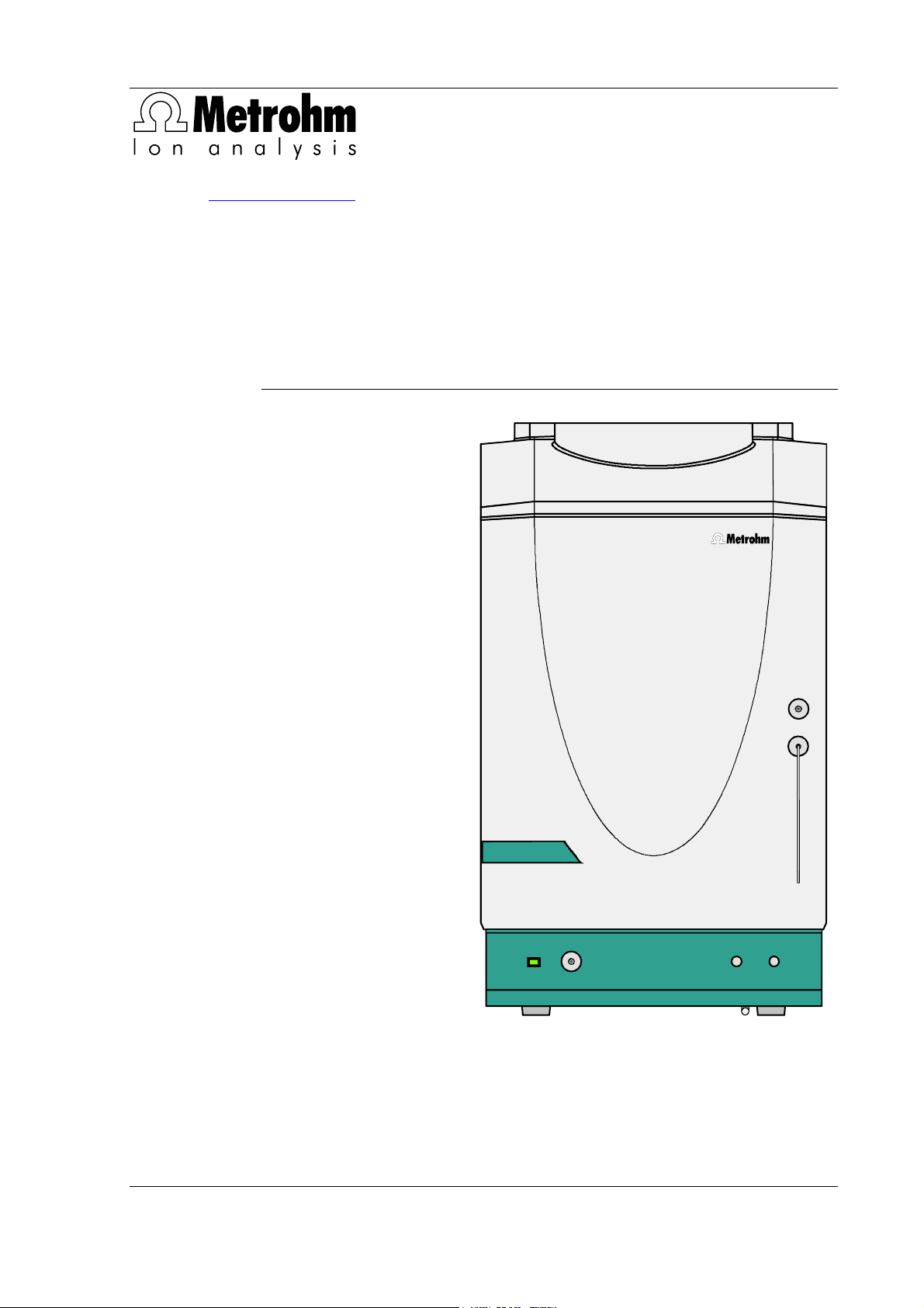
Figure 1: Front of the 761 SD Compact IC ............................................................... 3
Figure 2: Rear panel 761 SD Compact IC ................................................................ 4
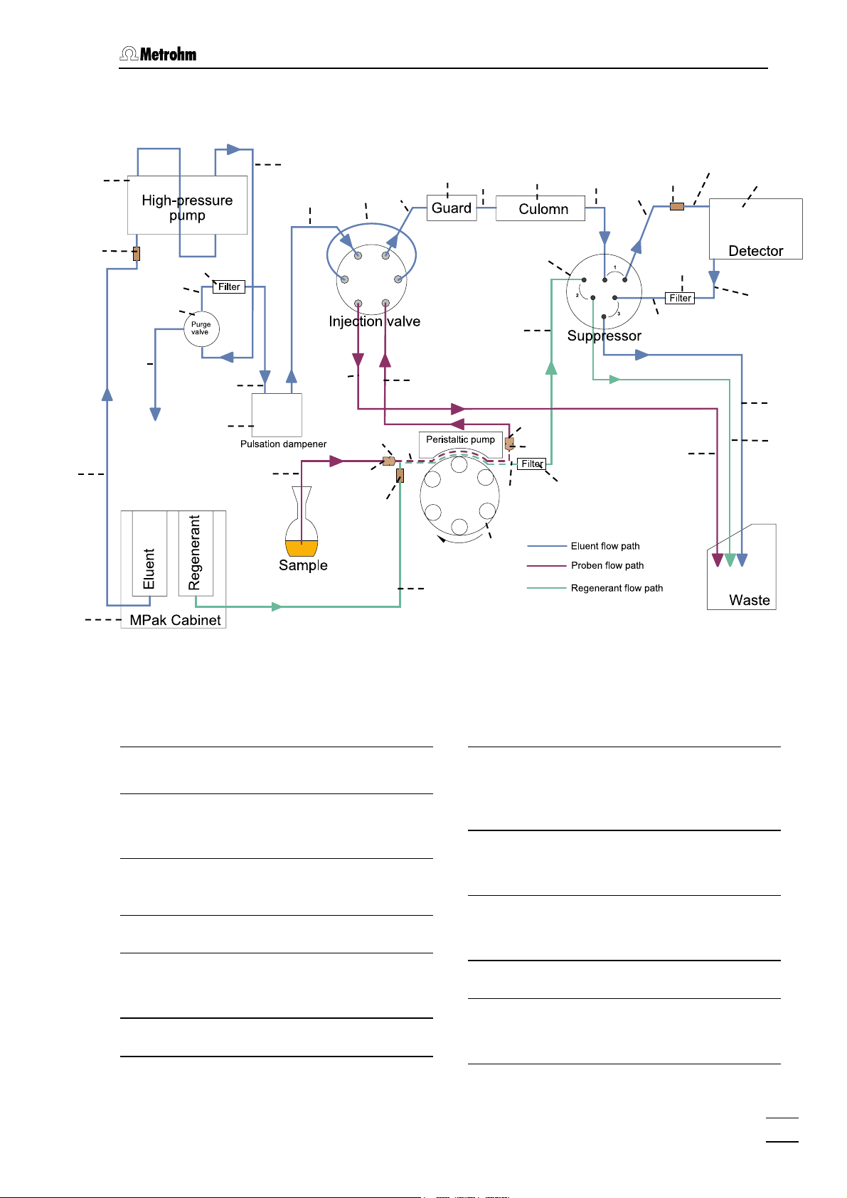
Figure 3: Connection schematic for 761 SD Compact IC ........................................ 5
Figure 4: Connectors for capillaries........................................................................ 13
Figure 5: PEEK couplings....................................................................................... 13
Figure 6: Connecting the filter unit PEEK ............................................................... 14
Figure 7: Position of the detector block 40 ............................................................ 15
Figure 8: Pump tubing for regenerant path ............................................................ 21
Figure 9: Flow schematic regenerant flow.............................................................. 22
Figure 10: Pump tubing for sample path.................................................................. 24
Figure 11: Flow schematic sample stream............................................................... 25
Figure 12: Rear panel ............................................................................................... 27
Figure 13: Setting the mains voltage........................................................................ 29
Figure 14: Connection of precolumn and separating column.................................. 41
Figure 15: Components of the pump head.............................................................. 94
Figure 16: Replacement of the piston seal 76.......................................................... 94
Figure 17: Components of inlet valve 77 and outlet valve 78.................................. 97
Figure 18: Assembling the suppressor .................................................................. 101
761 SD Compact IC / Instructions for Use 8.761.1043
IV
Page 9

1.1 Instrument description
1 Introduction
1.1 Instrument description
The 761 SD Compact IC is a version of the time-proven 761 Compact
IC which has been developed specifically for soft drink analysis. The
761 SD Compact IC is designed for determining phosphoric acid and
its intermediate products in soft drinks but also continues to offer all
functionalities of the original version.
The advantages of the 761 SD Compact IC over the conventional
methods of phosphoric acid analysis in soft drinks are its short analysis
times, its ease of operation and the option for automated sampling.
There is no need for time-consuming sample preparation and only
small quantities of chemicals are consumed (more environmentally
friendly).
The 761 SD Compact IC has a very compact housing accommodating
all equipment required for ion-chromatographic determination:
• Injection valve – this supplies the sample to the eluent stream by
switching over the flow paths.
• High-pressure pump – extremely low-pulsation dual piston pump
with a flow range of 0.2 to 2.5 mL/min and a maximum pressure
of 25 MPa (250 bar).
• Pulsation dampener – the pulsation dampener protects the sepa-
rating column reliably against damage even in the case of low-level
pressure fluctuations.
• Column chamber – perfect insulation of the housing not only cre-
ates thermally stable conditions for the separating column, but also
shields the system against electromagnetic interference.
• Column – Metrosep A Supp 1 HS anion column as IC separating
column; Metrosep RP Guard as protective precolumn.
• Suppressor – the Metrohm-Suppressor-Module (MSM) which is
already integrated features stable pressure characteristics, automatic regeneration, high performance and optimum reproducibility.
• Peristaltic pump – integrated, two-channel peristaltic pump with a
flow rate of 0.5 to 0.6 mL/min for regeneration of the suppressor
module and aspiration of the sample for manual operation.
• Detector – conductivity detector with excellent temperature stabil-
ity. The detector temperature fluctuates by less than 0.01°C and
can be matched optimally to ambient conditions.
761 SD Compact IC / Instructions for Use 8.761.1043
1
Page 10

1 Introduction
All components coming into contact with eluent and sample are metalfree. Ready-to-use eluents in certified MPaks are supplied for soft drink
analysis.
The 761 SD Compact IC is operated by means of a PC connected to
the RS232 interface. The 761 SD Compact IC can be controlled by the
«IC Net» software or by the “master” «IC Cap» software.
The systems required for soft drink analysis (and the methods linked to
them) are supplied on the installation CD.
The following instrument versions are available:
• 2.761.0420 761 SD Compact IC
• 2.761.0520 761 SD Compact IC with IC Sample Processor 766
for automated sample change
Principle:
The eluent flows on the eluent path through the injection valve into the
separating column and then into the detector. The sample flows on the
sample path also through the injection valve and the red sample loop
visible at the centre of the injection valve. At a specific instant (<Inject>; controlled by the program), the flow paths in the injection valve
are switched and the sample loop is reintegrated in the eluent path (it is
now no longer a part of the sample path). The sample quantity which is
located in the sample loop at the switchover instant is then entrained
with the eluent stream, thus entering the separating column (where the
actual chromatographic separation of the components occurs) and, finally, chromatographically separated, into the conductivity detector.
2
761 SD Compact IC / Instructions for Use 8.761.1043
Page 11

1.2 Parts and controls
1.2 Parts and controls
In this section you will find the numbers and designations of the parts
and controls of the 761 SD Compact IC. The numbering applies
throughout the instructions for use, i.e. bold numbers in the text (e.g.
4
) refer to the parts and controls illustrated here.
1.2.1 Front view
761 SD Compact IC
6
7
POWER
Figure 1: Front of the 761 SD Compact IC
1
2
3
4
5
Door to inner compartment
1
Feedthrough for aspirating tubing
2
Aspirating tubing
3
for sample
Feedthrough for capillaries
4
761 SD Compact IC / Instructions for Use 8.761.1043
Connection for drain tube
5
for discharging escaped fluid from the
inner compartment
Connection purge valve
6
Pilot lamp
7
This is on when the instrument is
switched on
3
Page 12

1 Introduction
1.2.2 Rear view
8
10
11
17
18
19
Type 1.761.
WARNING - Fire Hazard -
For continued protection replace only
with the same type and rating of fuse
Analog Output
Remote
Detector Block
RS 232
Waste B
Made by Metrohm Herisau Switzerland
9
Waste A
11
12
Transport securit y screws
13
14
100-120V:
220-240V:
Fuse
1,0A(T)
0,5A(T)
15
16
Figure 2: Rear panel 761 SD Compact IC
Opening for outlet capillaries
8
for discharge of eluent, regeneration
solution and sample solution
Opening for inlet capillaries
9
for supply of eluent, regeneration solution and sample solution
Opening for detector cable
10
Knurled screw
11
for fastening the rear panel
Detachable rear panel
12
Access to the inner compartment
Transport security screws
13
to secure the pump head when the instrument is transported
Mains switch
14
to switch instrument on and off:
I = ON 0 = OFF
20
21
Mains connection plug
15
Mains connection, see section 2.11
Fuse holder
16
Changing the fuses, see section 2.11.2
Serial number
17
Analogue output
18
output for analogue signal
Remote interface
19
Remote-I/O lines for connection of external devices
Connection for detector block
20
RS232 interface
21
PC connection
4
761 SD Compact IC / Instructions for Use 8.761.1043
Page 13
1.2 Parts and controls
1.2.3 Connection schematic
23
24
55
27
28
26
56
29
30
25
31
32 33
34
35 37
36
43
54
38
56
39
40
41
42
48
45
47
44
50
63
64
3
50
61
65
48
56
46
55
49
22
Figure 3: Connection schematic for 761 SD Compact IC
3 Aspirating tubing
for sample
MPak cabinet
22
for suspending eluent and regenerant bag
Tubing connection to MPak
23
6.1837.000
Pump head 6.2824.100
24
Connection capillary
25
Connection between pump head and
purge valve, permanently mounted
Purge valve
26
23
Connection capillary
27
PEEK capillary 6.1831.010 for
deaerating,
length L = 15 cm
Connection capillary
28
PEEK capillary 6.1831.010,
length L = 13 cm
Connection capillary
29
PEEK capillary 6.1831.010,
length L = 13 cm
Pulsation dampener 6.2620.150
30
Inlet capillary for injector
31
PEEK capillary 6.1831.010,
length L = 24 cm
761 SD Compact IC / Instructions for Use 8.761.1043
5
Page 14
1 Introduction
Sample loop 1.5 µL (6.1825.240)
32
PEEK sample loop
Column connection capillary
33
PEEK capillary 6.1831.010,
length L = 30 cm
Metrosep RP Guard 6.1011.020
34
Precolumn for protecting the separating column
Connection capillary
35
PEEK connection capillary between
precolumn and separating column
Metrosep A Supp 1 HS separating
36
column (6.1005.350)
IC separating column
Suppressor inlet capillary for elu-
37
ent ("Eluent")
PTFE capillary, permanently mounted
on suppressor, labelled "Eluent"
Suppressor outlet capillary for
38
eluent ("Detector")
PTFE capillary permanently mounted
on suppressor, labelled "Detector"
Inlet capillary to detector block
39
PEEK capillary, permanently
mounted
Detector block 1.732.0420
40
Outlet capillary from detector
41
block
PEEK capillary, permanently
mounted
Suppressor inlet capillary for elu-
42
ent ("H2O")
PTFE capillary, permanently mounted
on suppressor, labelled "H2O"
Suppressor module
43
Suppressor outlet capillary for
44
eluent ("Waste")
PTFE capillary, permanently mounted
on suppressor, leading to the waste,
labelled "Waste"
On instrument version 2.761.0520 with automated sample change
with the 766 IC Sample Processor, the aspirating tubing
by the PEEK capillary tubing
ple Processor) installed on the 766 IC Sample Processor. See Section
2.9. for installation of the 766 IC Sample Processor.
Suppressor inlet capillary for re-
45
generant
PTFE capillary, permanently mounted
on suppressor, labelled "H2SO4"
Suppressor outlet capillary for
46
regenerant ("Waste")
PTFE capillary, permanently mounted
on suppressor, leading into the
waste, labelled "Waste"
Connection capillary
47
PTFE capillary 6.1803.030, connection between pump tubing and injection valve
Connection capillary
48
PTFE capillary 6.1803.030, connection between injection valve and
waste container
Pump drive of the peristaltic
49
pump
Drive of the two-channel-peristaltic
pump for pumping sample and regenerant
50 Pressure screw 6.2744.010
54 PEEK coupling 6.2744.040
55 PEEK coupling 4.455.4500
Coupling for "tubing connection to
MPak"
56 Filter unit PEEK 6.2821.120
61 Pump tubing 6.1826.110 for H2SO
63 PEEK coupling 6.2744.030
64 Pump tubing 6.1826.110 for sam-
ple
65 PEEK coupling 6.2744.160
with tubing security device
3
is replaced
18
(see Instructions for Use 766 IC Sam-
4
6
761 SD Compact IC / Instructions for Use 8.761.1043
Page 15

1.3 Information on the Instructions for Use
1.3 Information on the Instructions for Use
Please read through these Instructions for Use carefully before you put
the 761 SD IC Compact IC into operation. The Instructions for Use
contain information and warnings to which the user must pay attention
in order to assure safe operation of the instrument.
1.3.1 Organisation
These Instructions for Use 8.761.1043 for the 761 SD Compact IC
provide a comprehensive overview of installation, startup procedure,
operation, fault rectification and technical specifications of this instrument. The Instructions for Use are organised as follows:
Section 1 Introduction
General description of instrument, parts and controls and safety notes
Section 2 Installation
Installation and connection of the instrument, of the accessories and of the software
Section 3 «IC Net»
Explanatory information on the user interface of the «IC
Net» control software
Section 4 «IC Cap
Explanatory information on the user interface
of the «IC Cap» control software
Section 5 Operation
Description of operation with manual and
automatic sample change, with «IC Net» and
«IC Cap» in each case
Section 6 Notes – Maintenance – Faults
Notes on ion chromatography, maintenance, fault
rectification, diagnostic tests and validation
Section 7 Appendix
Technical data, standard equipment, options, warranty, declarations of conformity and index
To find the required information on the instruments, you will find it an
advantage to use either the Table of contents or the Index at the
back.
761 SD Compact IC / Instructions for Use 8.761.1043
7
Page 16

1 Introduction
1.3.2 Notation and pictograms
The following notations and pictograms (symbols) are used in these Instructions for Use:
Fill Menu item, parameter or entry
value
in the software
SYSTEM STATE Program window
in the software
<OK> Button
in the software
20 Part or control of 761 SD
18 Part or control of 766
Hazard
This symbol draws attention to a
possible danger to life or of injury if
the associated directions are not
followed correctly. .
Warning
This symbol draws attention to
possible damage to instruments or
instrument parts if the associated
directions are not followed correctly.
Caution
This symbol marks important information. First read the associated
directions before you continue.
Comment
This symbol marks additional information and tips.
8
761 SD Compact IC / Instructions for Use 8.761.1043
Page 17

1.4 Safety notes
1.4 Safety notes
1.4.1 Electrical safety
While electrical safety in the handling of the 761 SD Compact IC is assured in the context of the specifications IEC/EN 61010-1 (prot. class 1,
degree of protection IP20), the following points should be noted:
• Mains connection
Setting of the mains voltage, checking the mains fuse and the
mains connection must be effected in accordance with the instruc-
tions in section 2.11.
• Opening the 761 SD Compact IC
If the 761 SD Compact IC is connected to the power supply, the instrument must not be opened nor must parts be removed from it, otherwise there is a danger of coming into contact with components
which are live. Hence, always disconnect the instrument from all voltage sources before you open it and ensure that the mains cable is
15
disconnected from mains connection
!
• Protection against static charges
Electronic components are sensitive to static charging and can be
destroyed by discharges. Before you touch any of the components
inside the 761 SD Compact IC, you should earth yourself and any
tools you are using by touching an earthed object (e.g. housing of the
instrument or a radiator) to eliminate any static charges which exist.
1.4.2 General precautionary rules
• Handling of solvents
Check all lines of the IC system periodically for possible leaks. Follow
the relevant instructions regarding the handling of flammable and/or
toxic solvents and their disposal.
• Periodic exchange of pump tubing
Pump tubing is consumable material and must be replaced from time
to time (see Section 6.2.9). Please take suitable measures to ensure
that any leakage on pump tubing or connections in unattended continuous operation does not cause damage (position the instrument at
the bottom and provide a receptacle for catching escaping fluid).
761 SD Compact IC / Instructions for Use 8.761.1043
9
Page 18

2 Installation
2 Installation
2.1 Flow chart
The following flow chart provides an overview of all installation work.
You will find more detailed information in the relevant section.
Setting up sect. 2.2
Installing detektor block sect. 2.4
Installing drain tubes
Installing eluent flow path sect. 2.6
Installing regenerant flow path sect. 2.7
Installing sample flow path
766 IC Sample
Processor
No
Replace rear panel
Mains connection
sect. 2.5
sect. 2.8
Yes
sect. 2.10
sect. 2.11
Connection to 766 IC Sample Processor
sect
. 2.9
Connecting PC sect
Installing software
Deaerating/Rinsing sect
Install guard and column sect. 2.15
10
761 SD Compact IC / Instructions for Use 8.761.1043
. 2.12
sect. 2.12.2
. 2.13 / 2.14
Page 19
2.2 Setting up the instrument
2.2 Setting up the instrument
2.2.1 Packaging
The 761 SD Compact IC is supplied together with the separately
packed accessories in special packagings containing shock-absorbing
foam linings designed to provide excellent protection. The instrument
itself is packed in an evacuated polyethylene bag to prevent the ingress
of dust. Please store all these special packagings as only they assure
transport of the instrument free from damage.
2.2.2 Check
After receipt, immediately check whether the shipment is complete and
has arrived without damage (compare with delivery note and list of
accessories in section 7.2). In the case of transport damage, see
instructions in section 7.4.1 "Warranty".
2.2.3 Location
Position the instrument in the laboratory at a location convenient for operation, free from vibrations and protected against a corrosive atmosphere and contamination by chemicals.
To avoid disturbing temperature influences on the insulated column
compartment, the instrument must be protected against direct
sunlight.
761 SD Compact IC / Instructions for Use 8.761.1043
11
Page 20
2 Installation
2.3 Description of the connections
2.3.1 Connection of capillaries/tubing
The connections for eluent, sample and regenerant consist of:
• PEEK capillaries 6.1831.010 (inner diameter = 0.25 mm)
• PTFE microcapillaries 6.1803.030 (inner diameter = 0.5 mm)
• PTFE tubing connections to the MPaks 6.1837.000 (inner di-
ameter = 1.5 mm)
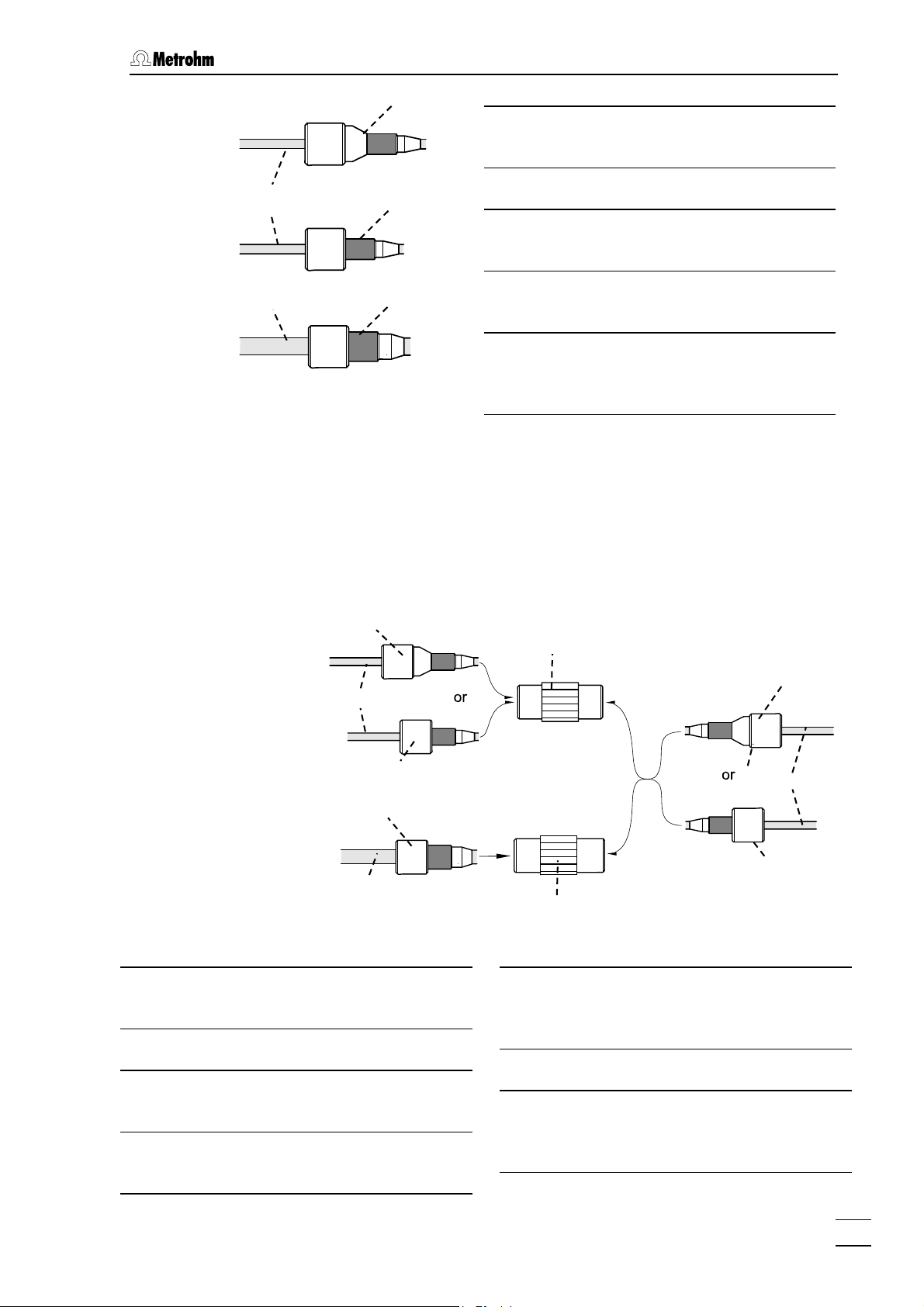
The PEEK capillaries and PTFE microcapillaries can be connected either with PEEK pressure screws 50 6.2744.010 (long) or PEEK
pressure screws 51 6.2744.070 (short, for connection to the IC
pump).
The "PTFE tubing connection to the MPak" 23 can be connected to the
PEEK pressure screw 52 4.422.4510 (wide).
The connectors must be fitted to the capillaries as follows in this case:
Capillaries provided with new connectors must feature a flawless, flat
cut edge. In order to ensure this, it is best to use the tubing cutter
6.2621.080.
1 Fit pressure screw
Slide the corresponding pressure screw (50, 51 or 52), as
shown in Figure 4 onto the capillary 53 (23 for MPak connection).
2 Insert the capillary into the connection
Slide the end of the capillary fully into the corresponding
connector (in order to avoid dead volume).
3 Tighten the pressure screw
Firmly tighten the pressure screw (50, 51 or 52) by hand (do not
use tools).
12
761 SD Compact IC / Instructions for Use 8.761.1043
Page 21
2.3 Description of the connections
50
23 Tubing connection to MPak
6.1837.000
Pressure screw 6.2744.010
50
53
51
Pressure screw 6.2744.070
51
for IC pump
Pressure screw 4.422.4510
52
23
52
for tubing connection 23 to MPak
Capillary
53
PEEK capillary 6.1831.010 or PTFE-
Figure 4: Connectors for ca-
microcapillary 6.1803.030
pillaries
2.3.2 Connection between capillaries/tubing
Capillaries and tubing can be connected together using PEEK couplings. If PEEK capillaries 6.1831.010 and/or PTFE microcapillaries
6.1803.030 are to be connected together, use the PEEK coupling
6.2744.040. If the "tubing connection to the MPak" is to be connected,
use the PEEK coupling 4.422.4500.
50
53
51
52
23
Figure 5: PEEK couplings
23 Tubing connection to MPak
6.1837.000
50 Pressure screw 6.2744.010
51 Pressure screw 6.2744.070
for IC pump
52 Pressure screw 4.422.4510
for tubing connection 23 to MPak
54
55
53 Capillary
PEEK capillary 6.1831.010 or PTFEmicrocapillary 6.1803.030
PEEK coupling 6.2744.040
54
PEEK coupling 4.455.4500
55
coupling for "tubing connection to the
MPak"
50
53
51
761 SD Compact IC / Instructions for Use 8.761.1043
13
Page 22

2 Installation
Capillaries may also be connected together via PEEK inline filters, see
Section 2.3.3.
2.3.3 Filter unit PEEK
Three PEEK filter units 6.2821.120 should be fitted in the 761 SD
Compact IC.
The first one should be fitted between IC pump head 24 and pulsation
dampener 30. It serves to avoid contamination by abrasive particles of
the piston seals.
The two other filter units are installed upstream of the suppressor module. One upstream of the inlet capillary 42 (labelled "H2O") in the return
path from the detector to the suppressor in the eluent path (see Section
2.6.6). The other one upstream of the inlet capillary 45 (labelled
"H2SO4"), between peristaltic pump and suppressor module in the regenerant path (see Section 2.7.2). They serve to protect the suppressor
module against foreign particles and bacterial growth.
For the connection of the filter unit, please note the flow direction arrow printed on the housing.
53
50
Figure 6: Connecting the filter unit PEEK
50 Pressure screw 6.2744.010
53 Capillary
PEEK capillary 6.1831.010 or PTFEmicrocapillary 6.1803.030
Filter unit PEEK 6.2821.120
56
56
50
53
14
761 SD Compact IC / Instructions for Use 8.761.1043
Page 23
2.4 Connection of the detector block
w
2.4 Connection of the detector block
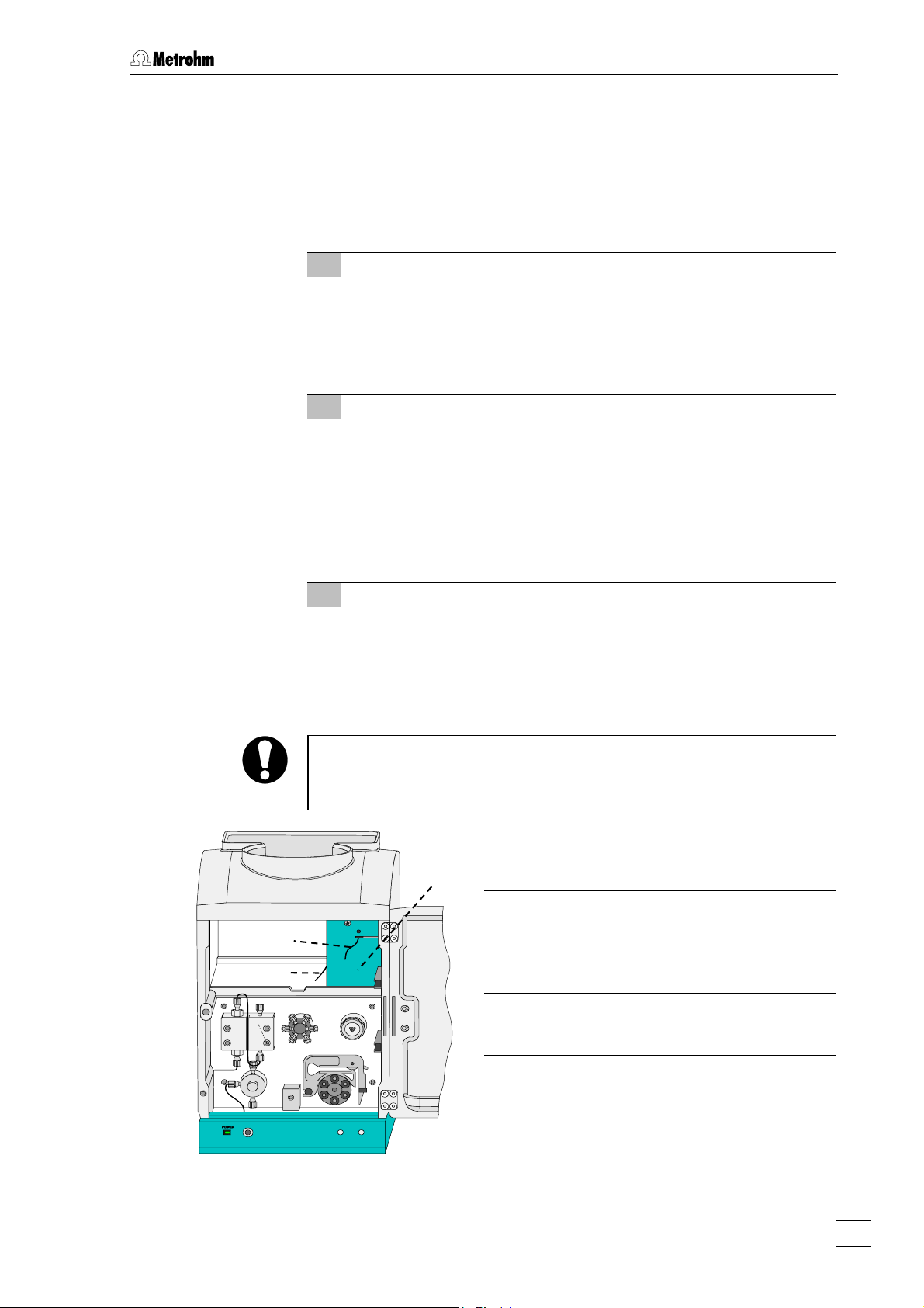
The metal-free detector block 1.732.0420 which must be fitted in the
instrument and connected belongs to the scope of delivery of the 761
SD Compact IC. Proceed as follows:
1 Note the cell constant
• The cell constant c = XX.X /cm, measured at the works, is
printed on the rear side of the detector block. Note this value;
it must subsequently be entered in the software in order to
ensure that an exact display of the conductivity is obtained
(see Section 2.12.3).
2 Install detector block
• Unscrew the two upper knurled screws 11 from the upper
rear panel 12 of the 761 SD Compact IC, slacken the t
lower knurled screws 11 a little and remove the rear panel
(see Figure 2).
• Position the detector block 40 from the rear onto the space
provided in the 761 SD Compact IC and push it fully to the
front (see Figure 7).
o
39
41
3 Connect detector block
• Pull the grey connecting cable permanently attached to the
detector block 40 out through the opening (where the upper
rear panel 12 previously was) on the rear of the 761 SD
Compact IC and plug it in to connection 20 "Detector Block"
of the 761 SD Compact IC.
Since other connections need to be routed through the rear openings
of the 761 SD Compact IC later on, you should not fit the rear panel
back on until the end of the installation procedure (see Section 2.10).
40
39 Inlet capillary to detector block
PEEK capillary, permanently attached
40 Detector block 1.732.0420
41 Outlet capillary from detector block
PEEK capillary, permanently attached
12
40
Figure 7: Position of the detector block
761 SD Compact IC / Instructions for Use 8.761.1043
15
Page 24

2 Installation
39
The inlet and outlet capillaries (
block must be fitted in the eluent path as described in Sections 2.6.5
and 2.6.6.
and 41) to and from the detector
2.5 Installation of the MPak cabinet and connection of the drain tubes
2.5.1 Installing the MPak cabinet
Install the MPak cabinet as shown on the drawing accompanying the
package. Position it next to the 761 SD Compact IC and suspend the
eluent and regenerant MPaks from the crossbars. Since eluent and regenerant are supplied from the rear to the 761 SD Compact IC, the outlets of the MPaks should point to the rear.
2.5.2 Drain tube for inner compartment
The 761 SD Compact IC features a connector (5) for escaped fluids on
the front panel. A drain tube can be fitted to the connector. Proceed as
follows:
1 Connect drain tube
• Plug the silicone tube 6.1816.020 onto the nipple.
2 Route the drain tube into an outlet
• Route the other end of the drain tube into an outlet and se-
cure it at this point.
2.5.3 Drain tube for MPak cabinet
The basin of the MPak cabinet 22 features a connection for fluids escaping from the MPaks to which a drain tube can be fitted. Proceed as
follows:
1 Connect drain tube
• Plug the silicone tubing 6.1816.020 onto the nipple.
2 Route the drain tube into an outlet
• Route the other end of the drain tube into an outlet and se-
cure it there.
16
761 SD Compact IC / Instructions for Use 8.761.1043
Page 25

2.6 Installing the eluent path
2.6 Installing the eluent path
2.6.1 High-pressure pump – Removing the transport security screws
The pump head is locked with three transport security screws 13 in order to prevent damage to the pump drive during transport (see Figure
2). These transport security screws must be removed before placing
the high-pressure pump into operation. Also remove the red sticker attached to the pump head 24.
The three transport security screws must be refitted every time before
a major transport operation of the pump in order to avoid damage to
the pump head.
2.6.2 Connection MPak → high-pressure pump
The eluent MPak must be connected to the pump head 24 via the tubing connection 23 6.1837.000.
First connect the end at the pump head and then, not before, connect
the end at the MPak output. The eluent will start to drain out if you
connect the end at the MPak output first.
Procedure when connecting the tubing connection:
1 Connect the tubing connection using the PEEK
coupling to the pump head
• Connect the tubing connection 23 6.1837.000 using the
PEEK coupling 55 (already pre-fitted to the tubing) to the
capillary inlet of the pump head 24.
23
2 Connect the tubing connection to the eluent MPak
outlet
• Connect the other end of the tubing connection 23 to the elu-
52
ent MPak outlet (pierce the connection and turn it through 90°
clockwise).
55
51 53
761 SD Compact IC / Instructions for Use 8.761.1043
17
Page 26
2 Installation
2.6.3 Connection high-pressure pump → injection valve
In order to protect the column material against hammering effects owing to injection, the supplied pulsation dampener 6.2620.150 must
be fitted between high-pressure pump and injection valve of the 761 SD
Compact IC.
Connection between pump head and injection valve (see Figure 3):
Pump head 24 → connection capillary 25 → purge valve 26 → connection capillary 28 → inline filter 56 → connection capillary 29 →
pulsation dampener 30 → connection capillary 31 → injection valve
When delivered, a PEEK coupling 54 is fitted in place of the pulsation
dampener 30 between connection capillary 29 and 31. The PEEK coupling should be removed and the pulsation dampener should be fitted
at the same position. Proceed as follows:
1 Position the pulsation dampener
Place the pulsation dampener 30 6.2620.150 in the inner compartment of the 761 SD Compact IC on the bottom.
2 Remove the PEEK coupling
Remove the PEEK coupling 54 located between connection
capillary 29 and 31.
3 Connect the pulsation dampener
Connect the connection capillary 29 and connection capillary 31
to the pulsation dampener.
29
31
56
50
50
30
The pulsation dampener is filled with isopropanol and must be rinsed
with eluent before connection of a separating column (see Section
2.13.2).
The pulsation dampener 6.2620.150 can be operated in both directions.
18
761 SD Compact IC / Instructions for Use 8.761.1043
Page 27
2.6 Installing the eluent path
2.6.4 Connection injection valve → suppressor
The precolumn and the separating column are fitted between injection
valve and suppressor in the operational system (see Figure 3). How-
ever, since the system should first be rinsed without columns (so as not
to damage them), the columns may be fitted only later (see Section
2.15). A PEEK coupling 54 is fitted as a temporary replacement.
Proceed as follows:
1 Fit the PEEK coupling 54
Connect the column connection capillary 33 to the "suppressor
inlet capillary for eluent ("Eluent")" 37 via the PEEK coupling 54
(see Section 2.3.2).
Temporary connection schematic (c.f. Figure 3):
33
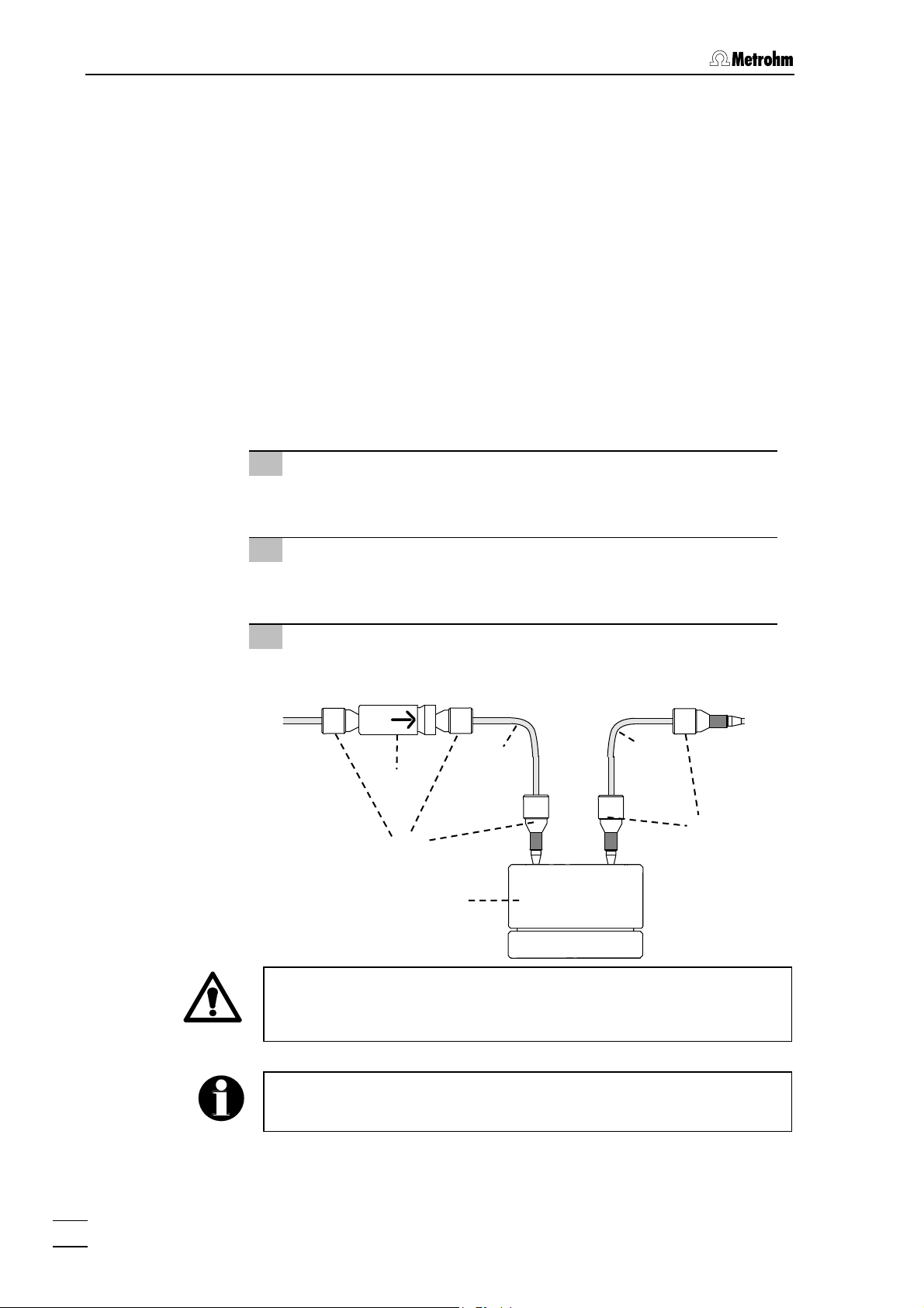
2.6.5 Connection suppressor → detector
From the suppressor, the eluent stream is routed on to the detector
(see Figure 3). The connection is made using a PEEK coupling. Proceed as follows:
1 Fit the PEEK coupling 54
Connect the "suppressor outlet capillary for eluent ("Detector")"
38 via the PEEK coupling 54 (see Section 2.3.2) to the "inlet ca-
pillary to detector block" 39.
37
54
2.6.6 Connection detector → suppressor
Downstream of the detector, the eluent flow is routed back into the
suppressor. It rinses the suppressor there after its regeneration phase.
A filter unit PEEK is fitted between detector and suppressor. Proceed as
follows:
1 Fit the filter unit PEEK
Connect the "outlet capillary from detector block" 41 via the filter
unit PEEK 54 (see Section 2.3.3) to the "suppressor inlet capillary for eluent ("H2O")" 42.
761 SD Compact IC / Instructions for Use 8.761.1043
19
Page 28

2 Installation
2.6.7 Connection suppressor → waste
Route the "suppressor outlet capillary for eluent ("Waste")" 44 at the rear
out of the 761 SD Compact IC into a waste container.
2.7 Installing the regenerant path
The regenerant (100 mmol/L H2SO4) is aspirated with the peristaltic
pump from the regenerant MPak and forced into the suppressor via the
filter unit PEEK. From the suppressor, it is then routed into a waste container (see Figure 9).
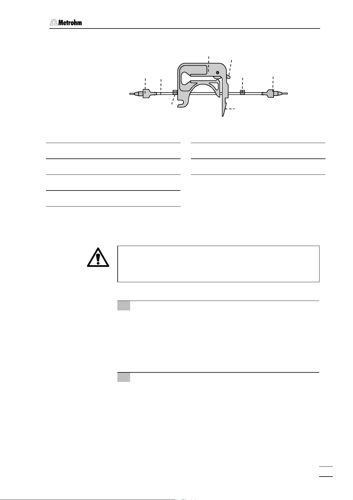
2.7.1 Fitting the pump tubing for regenerant
One channel of the two-channel peristaltic pump is used to pump the
regenerant. Fit a pump tubing 61 6.1826.110 as follows:
1 Disengage the tubing cartridges
• Detach and disengage the two tubing cartridges 57 above
the pump drive 49 by pressing in the snap-action lever 59 on
the retaining bracket.
• Press the pressure lever 58 down fully.
2 Fit the couplings 60
• Fit one coupling 60 6.2744.110 onto each end of the pump
tubing 61 6.1826.110. Moistening the tip of the coupling
lightly will make it easier to slip it on.
3 Fit the pump tubing
• Insert the fitted pump tubing 61 as shown in Figure 8 into the
tubing cartridge. The left-hand stopper 62 should latch into
the corresponding fixture on the left-hand side of the tubing
cartridge.
4 Reengage the tubing cartridge
• Reengage the tubing cartridge with pump tubing 61 in the re-
taining bracket. Engage it at the left first and then press the
right-hand side down until the snap-action lever 59 engages.
Ensure that the pump tubing is not kinked when doing this.
• Leave the other tubing cartridge outside. It is fitted with the
pump tubing for the sample path (see Section 2.8.1).
20
761 SD Compact IC / Instructions for Use 8.761.1043
Page 29
2.7 Installing the regenerant path
Tubing cartridge
57
Pressure lever
58
Snap-action lever
59
Coupling 6.2744.110
60
57
58
60
61
62
62
59
Figure 8: Pump tubing for regenerant path
Pump tubing 6.1826.110 for H
61
Stopper orange-yellow
62
60
2SO4
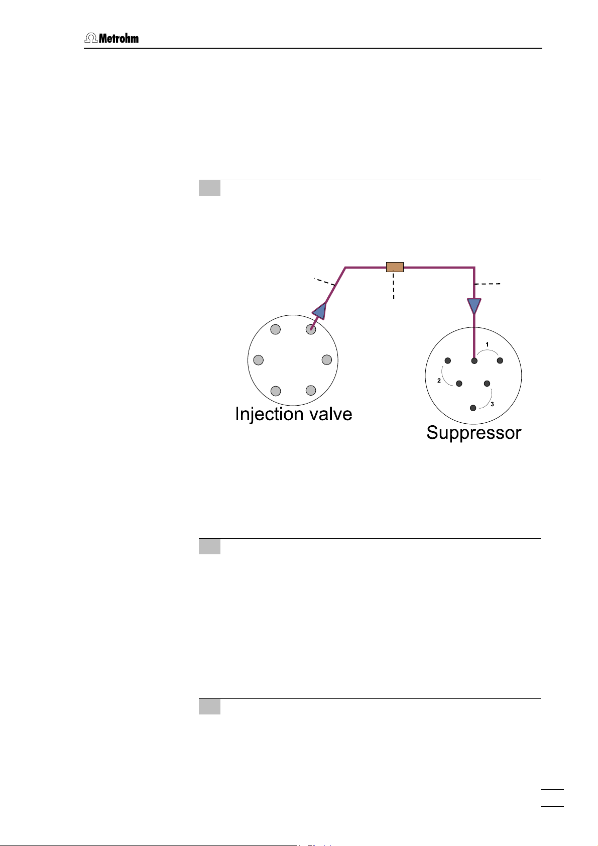
2.7.2 Connection regenerant-MPak → pump tubing → suppressor
→ waste
The connections to the pump tubing, suppressor and waste must be
connected first. Then, and not before, connect the end at the MPak
outlet. If the end at the MPak outlet is connected first, the regenerant
(H
Proceed as follows:
1 Connection Pump tubing - Suppressor
2 Connection Suppressor - Waste
) will begin to escape.
2SO4
• Screw the filter unit PEEK 56 6.2821.120 onto the coupling 60
6.2744.110 at the right-hand end (flow outlet) of the pump
tubing 61 fitted in the peristaltic pump. Note the flow direction
arrow on the filter unit.
• Firmly screw the "suppressor inlet capillary for regenerant
("H2SO4")" 45 onto the filter unit 56 with a pressure screw 50
6.2744.010 (see also Section 2.3.3).
• Route the "suppressor outlet capillary for regenerant
("Waste")" 46 at the rear out of the 761 SD Compact IC into a
waste container.
761 SD Compact IC / Instructions for Use 8.761.1043
21
Page 30

2 Installation
3 Connection MPak pump tubing
The regenerant MPak and pump tubing are connected using the
"tubing connection to MPak" 23 6.1837.000:
• First connect the end which is to be connected to the pump
tubing!
• Pressure screw 52 4.422.4510 and coupling 55 4.455.4500
are already pre-fitted on the "tubing connection to MPak" 23
6.1837.000. Screw this coupling 55 4.455.4500 onto the coupling 60 6.2744.110 plugged onto the left-hand end of the
pump tubing (flow inlet).
• Latch the other end of the "tubing connection to MPak" 23
6.1837.000 at the outlet of the regenerant MPak.
52
23
60
55
Figure 9: Flow schematic regenerant flow
23 Tubing connection to MPak
6.1837.000
45 Suppressor inlet capillary for re-
generant
PTFE capillary, permanently attached
to the suppressor, labelled "H2SO4"
46 Suppressor outlet capillary for re-
generant ("Waste")
PTFE capillary, permanently attached
to the suppressor; leads in to the
waste, labelled "Waste"
60
50
46
61
56
45
52 Pressure screw 4.422.4510
for "tubing connection to MPak" 23
55 PEEK coupling 4.455.4500
Coupling for "tubing connection to
MPak" 23
56 Filter unit PEEK 6.2821.120
60 Coupling 6.2744.110
61 Pump tubing 6.1826.110 for H2SO4
50 Pressure screw 6.2744.010
22
761 SD Compact IC / Instructions for Use 8.761.1043
Page 31

2.8 Installing the sample path
2.8 Installing the sample path
The sample is aspirated with the peristaltic pump from the sample vessel into the injection valve and finally ejected into a waste container.
See Section 2.9. for connection of the 766 IC Sample Processor
(supplied together with instrument version 2.761.0520).
2.8.1 Fitting the pump tubing for sample
The second channel of the two-channel peristaltic pump is used to
pump the sample. Fit the pump tubing 64 6.1826.110 as follows:
1 Disengage the tubing cartridges
• The tubing cartridge for the pump tubing should still be out-
side from installing the regenerant path. If not, remove it as
specified in Section 2.7.1.
2 Fit the coupling 63
• Plug a coupling 63 6.2744.030 onto the left-hand of the pump
tubing 64 6.1826.110. Lightly moistening the tip of the coupling will make it easier to slip on.
3 Fit the coupling with tubing security device 65
Fit a coupling with tubing security device 65 6.2744.160 onto the
right-hand end of the pump tubing 64 6.1826.110 (see Figure
10):
• Dismantle the tubing security device and first slide the un-
ion nut and the thrust piece onto the tubing.
• Plug the tubing onto the coupling and screw the union nut
onto the coupling in order to lock the tubing.
4 Insert the pump tubing
• Insert the fitted pump tubing 64, as shown in Figure 10, into
the tubing cartridge. The left-hand stopper 62 should engage
in the corresponding fixture on the left-hand side of the tubing
cartridge when doing this.
5 Reengage the tubing cartridge
• The tubing cartridge with the pump tubing 61 for the regener-
ant path should already be engaged (see Section 2.7.1).
Slide it to the rear.
• Engage the tubing cartridge with pump tubing 64 for the
sample path at the front into the retaining bracket. Engage it
at the left first and then push the right-hand side down until
the snap-action lever 59 engages. Ensure that the pump tubing is not kinked when doing this.
761 SD Compact IC / Instructions for Use 8.761.1043
23
Page 32

2 Installation
57
58
62
63
Figure 10: Pump tubing for sample path
57 Tubing cartridge
58 Pressure lever
59 Snap-action lever
62 Stopper orange-yellow
64
59
63
64
65
62
PEEK coupling 6.2744.030
Pump tubing 6.1826.110 for sample
PEEK coupling 6.2744.160
with tubing security device
65
2.8.2 Connection sample vessel → pump tubing → injection valve
→ waste
Proceed as follows in order to make the connections for the sample
path:
1 Connection Sample vessel - pump tubing
The sample is aspirated with the aspirating tubing 3:
• The aspirating tubing 3 is routed through the "feedthrough for
aspirating tubing" 2 out of the front door into the sample vessel. It is fixed in position on the feedthrough 2 with a rotary
nipple (see Section 2.9.2 if using the 766 IC Sample Processor).
• Detach the other end of the aspirating tubing 3 with pressure
screw 50 from the injection valve (it is fitted there only for delivery purposes) and screw it firmly onto the PEEK coupling
63 on the left-hand end of the pump tubing (flow inlet) (see
Figure 11).
24
761 SD Compact IC / Instructions for Use 8.761.1043
Page 33

2.8 Installing the sample path
2 Connection pump tubing - injection valve
• The sample is forced into the injection valve via the connec-
tion capillary 47.
• Detach the connection capillary 47 with the two pressure
screws 50 from the outlet of the injection valve and from the
opening in the door (it is fitted there only for delivery purposes).
• Screw the ends of the connection capillary 47 to the inlet of
the injection valve and to the PEEK coupling 65 on the righthand end of the pump tubing (flow outlet) using one pressure
screw 50 (see Figure 11).
3 Connection injection valve - waste container
The connection capillary 48 routes the sample from the injection
valve into the waste:
• Connect the supplied PTFE capillary 6.1803.030 with a pres-
sure screw 50 6.2744.010 to the outlet of the injection valve.
• Route the other end at the rear out of the 761 SD Compact IC
into the waste container. Wait until after the rear panel has
been fitted to cut it to size (see Section 2.10).
50
3
Figure 11: Flow schematic sample stream
3 Aspirating tubing
for sample
47 Connection capillary
PTFE capillary 6.1831.030, connection
pump tubing - injection valve
48 Connection capillary
PTFE capillary 6.1831.030, connection
injection valve - waste container
63
64
48
50
65
47
63 PEEK coupling 6.2744.030
64 Pump tubing 6.1826.110 for sample
65 PEEK coupling 6.2744.160
with tubing security device
50 Pressure screw 6.2744.010
The sample stream should be routed into a waste container downstream of the injection valve (see Section 2.8.2.).
761 SD Compact IC / Instructions for Use 8.761.1043
25
Page 34

2 Installation
2.9 Connecting the 766 IC Sample Processor
On instrument version 2.761.0520, the related 766 IC Sample Processor
should now be installed and connected.
The 766 IC Sample Processor is an automatic sampler for ion chromatography. The instrument accommodates max. 127 samples (sample
vessels: 2.5 mL or 11 mL) which are automatically transferred to the
sample loop attached to the injection valve of the 761 SD Compact IC.
Sample changing and filling of the sample loop are each started by a
signal output on the 761 SD Compact IC (761 SD Compact IC as "master").
2.9.1 Installing the 766 IC Sample Processor
Please refer to the supplied Instructions for Use 766 IC Sample Processor (8.766.1001) for installation of the 766 IC Sample Processor.
2.9.2 Connecting the 766 IC Sample Processor
Connect the 766 IC Sample Processor as follows:
1 Electrical connection 761 – 766
• Connect the remote end of cable 6.2125.110 to the RS232
connection 32
Sample Processors.
• Connect the other end to the COM2 output of the PC.
2 Tubing connection 766 – injection valve
• Undo the rotary nipple which is screwed in on the inner com-
partment side of the "feedthrough for aspirating tubing" 2.
• Pull the aspirating tubing 3 fully out of the "feedthrough for
aspirating tubing" 2 and unscrew it from the injection valve.
• Cut the PEEK capillary tubing 18
766) installed on the 766 IC Sample Processor to the required
length.
• Pull the free end of the PEEK capillary tubing 18
tions for Use 766) through the "feedthrough for aspirating tubing" 2 into the inner compartment of the 761 SD Compact IC
and screw it on to the inlet of the injection valve which is now
free (see also Figure 11) using a PEEK pressure screw
6.2744.010.
• Screw the rotary nipple on the inner compartment side of the
"feedthrough for aspirating tubing" 2 back on and thus fix the
transfer tubing 18
(see Instructions for Use 766) of the 766 IC
(see Instructions for Use 766) in position.
(see Instructions for Use
(see Instruc-
26
761 SD Compact IC / Instructions for Use 8.761.1043
Page 35

2.10 Fitting the rear panel
2.10 Fitting the rear panel
Now refit the rear panel which was removed during installation (Section
2.4). Place the incoming and outgoing cables and tubing at the rear
into the openings in the rear panel.
Figure 12: Rear panel
8 Opening for outlet capillaries
for discharge of eluent, regeneration
and sample solution
9 Opening for inlet capillaries
for supply of eluent, regeneration and
sample solution
10
Waste B
8
Waste A
9
11
10 Opening for detector cable
11 Knurled screws
for fastening the rear panel
Metrohm recommends the following distribution over the openings:
Connection Opening leads to
• Suppressor outlet capillary for eluent ("Waste") 44
• Suppressor outlet capillary for regenerant ("Waste") 46
8
• Waste container
• Connection capillary 48
• Tubing connection to eluent MPak 23
• Tubing connection to regenerant MPak 23
• Detector connection cable
9
10
• Eluent MPak
• Regenerant MPak
• Input
"Detector Block"
Then fit the rear panel, fit the upper 2 knurled screws 11 and firmly
screw all 4 knurled screws 11 tight.
761 SD Compact IC / Instructions for Use 8.761.1043
27
Page 36

2 Installation
2.11 Mains connections
Next connect the 761 SD Compact IC to the electrical mains. Separating column and precolumn will not yet have been fitted. They are fitted
only after rinsing the new equipment components (see Section 2.15).
Follow the instructions below for connecting to the power supply. If the
instrument is operated with a mains voltage set wrongly and/or wrong
mains fuse, there is a danger of fire!
2.11.1 Setting the mains voltage
Before switching on the 761 SD Compact IC for the first time, check that
the mains voltage set on the instrument (see Figure 13) matches the local mains voltage. If this is not the case, you must reset the mains voltage on the instrument as follows:
1 Disconnect mains cable
Disconnect mains cable from mains connection plug 15 of the
761 SD Compact IC.
2 Remove fuse holder
Using a screwdriver, loosen the fuse holder 16 below the mains
connection plug 15 and take it out completely.
3 Check and change the fuse
Carefully remove the fuse installed for the desired mains voltage
out of the fuse holder 16 and check its specifications (the position of the fuse in the fuse holder is marked by the white arrow
imprinted next to the mains voltage range):
100…120 V 1.0 A (slow-blow) Metrohm No. U.600.0016
220…240 V 0.5 A (slow-blow) Metrohm No. U.600.0013
4 Insert fuse
Change the fuse if necessary and reinsert it in the fuse holder
16.
5 Fit the fuse holder
Depending on the desired mains voltage, insert the fuse holder
16 in the 761 SD Compact IC so that the corresponding mains
voltage range can be read normally and the adjacent white arrow points to the white bar imprinted below the fuse holder (see
Figure 13).
28
761 SD Compact IC / Instructions for Use 8.761.1043
Page 37

2.11 Mains connections
V
220 – 240 V
14
15
16
2.11.2 Fuses
100 –120
14 Mains switch
Switch for switching the instrument on
and off:
I = ON 0 = OFF
15 Mains connection plug
Mains connection, see Section 2.11.3
16 Fuse holder
220 - 240 V
100 - 120 V
100 - 120 V
220 - 240 V
Figure 13: Setting the
mains voltage
One of the two fuses 1 A/slow-blow for 100…120 V or 0.5 A/slow-blow
for 220…240 V is installed in the fuse holder 16 of the 761 SD Compact
IC as standard.
Ensure that the instrument is never put into operation with fuses of another type; otherwise there is a danger of fire!
For checking or changing fuses, proceed as described in Section
2.11.1.
2.11.3 Mains cable and mains connection
Mains cable
The instrument is supplied with one of three mains cables
• 6.2122.020 with plug SEV 12 (Switzerland, …)
• 6.2122.040 with plug CEE(7), VII (Germany, …)
• 6.2133.070 with plug NEMA 5-15 (USA, …)
which are three-cored and fitted with a plug with an earthing pin. If a different plug has to be fitted, the yellow/green lead (IEC Standard) must
be connected to protective earth (protection class 1).
Any break in the earthing inside or outside the instrument can make it
a hazard!
Mains connection
Plug the mains cable into the mains connection plug 15 of the 761 SD
Compact IC (see Figure 13).
2.11.4 Switching the instruments on/off
The 761 SD Compact IC is switched on and off using the mains switch
14. When the instrument is switched on, the mains pilot lamp 7 lights.
761 SD Compact IC / Instructions for Use 8.761.1043
29
Page 38

2 Installation
2.12 Connection to the PC
The next step is to connect the 761 SD Compact IC to the PC.
2.12.1 Connecting cable 6.2134.100
Always switch off the 761 SD Compact IC and PC before you connect
the two instruments with cable 6.2134.100.
Connect the RS 232 interface 21 on the 761 SD Compact IC to the serial COM1 port of the PC using the connecting cable 6.2134.100 (9pin/9-pin).
2.12.2 Software installation
The CD A.705.001 with software package «SD Analyzer 1.0» is supplied
with the 761 SD Compact IC. The two programs «IC Net» (see Section
3) and «IC Cap» (see Section 4), and in addition to the «Autodatabase»,
are installed when installing «SD Analyzer 1.0». The software runs under
the Windows 2000 and Windows XP operating systems and must be installed as follows:
1 Install program
• Insert the installation CD A.705.001 into your CD-ROM drive.
• Select
stallation CD. Follow the on-screen prompts of the Setup
program.
Metrohm recommends that you install the software in the stated default destination folder C:\Metrohm\SD Analyzer. If you install it to another location, you must (if you wish to work with «IC Cap») adapt the
path for chromatogram directory (in the Processing registry tab of the
METHOD SETUP window) for all used methods (see Section 3.1.3 and
the Software Instructions for Use «IC Net 2.3» Section 7.3.4).
2 766 IC Sample Processor
During installation, you will see the prompt "Do you work with
766 IC sample processor". Your selection will determine what
configuration is loaded in «IC Cap» when you install it (see also
Section 4.2).
Run in the Start menu and open file Setup.exe on the in-
30
761 SD Compact IC / Instructions for Use 8.761.1043
Page 39

2.12 Connection to the PC
3 Files
The installation program copies the files from the installation CD
to the directory which you specify and also creates the following
subdirectories:
\Metrohm\Sd Analyzer\Ic Net\
Data Directory for data files (*.chw) and
batch reprocessing files (
Devices Directory for device drivers (*.dev)
ExcelReport Directory for the Excel reports
ICCap Directory for «IC Cap» installation files and
«IC Cap» configuration files (
Methods Directory for method files (*.mtw)
Reports Directory for report files (*.txt)
and graphic files (
Systems Directory containing system files (*.smt) and
sample table files (
*.wmf)
*.que).
*.bar)
*.cfg)
4 Registration
• Please send us your registration card 8.761.8047 as soon as
possible so that we can register you as an official purchaser.
As a registered purchaser, you will receive any revised program versions at a special price.
The installed files are generally not write-protected. To prevent these
files from being deleted by mistake, switch on the write-protection or
make a backup copy in another directory.
2.12.3 Basic settings «IC Net»
The procedure for starting and quitting the software is described in the
Software Instructions for Use «IC Net 2.3» Section 2.
Add User window (see below) opens the first time you launch the
The
program after installing the software and a user with Administrator access rights is created.
You are advised to create the other users straight after installation. See
Software Instructions for Use «IC Net 2.3», Section 3.2 for creating users.
761 SD Compact IC / Instructions for Use 8.761.1043
31
Page 40

2 Installation
Enter cell constant
Now enter the cell constant (see Section 2.4) printed on the detector
block. Proceed as follows:
1 Open and connect a system
• Click on File / Open / System in the main window. In the window
which now opens, select file
startup.smt and click on <Open>.
You will see the following system window:
• Select the
Connect to workplace menu item of the Control menu
in this window.
2 Open the window for hardware settings
• Click with the right mouse button on the 761 image in the sys-
tem window and choose menu item
Hardware. You will see the
following window for the hardware settings:
3 Enter the cell constant
• Enter the cell constant printed on detector block 1.732.0420
in field
• Click on
Cell constant.
<OK> to save the settings and close the window.
32
761 SD Compact IC / Instructions for Use 8.761.1043
Page 41

2.12 Connection to the PC
2.12.4 Basic settings «IC Cap»
Logging in
The first time you start the «IC Cap» software, you must log in without
User or Password. The particular configuration loaded the first time you
open the program depends on whether you work with or without 766 IC
Sample Processor (you must make this selection during the installation
process, see Section 2.12.2).
Without 766 IC Sample Processor:
manual.cfg (see Section 4.2.2)
With 766 IC Sample Processor: auto.cfg (see Section 4.2.3)
The first time you log in, you should define the Administrator and other
users.
Defining Administrator/Users
In order to do this, open the
mouse button (see Section 4.2). Then, in the General tab of the
FIGURATION
Level (level: Administrator) and Password. For the Administrator, enter
the same
window, define the Administrator by entering User with
user with the same password which you already defined in «IC
CONFIGURATION window with the right
CON-
Net».
Then define the other users. For the users, enter the same
same
password which you already defined in «IC Net». See the Adminis-
user with the
trator Manual «IC Cap 2.0», Section 3.2 for creating users.
The users are a part of the configuration and are saved together with
it.
Save configuration
Select the Miscellaneous tab in the
CONFIGURATION window and
click on the <Store Configuration> button. Save the configuration
under a separate name.
Close the software again (see Administrator Manual «IC Cap 2.0» Sec-
tion 3.2).
761 SD Compact IC / Instructions for Use 8.761.1043
33
Page 42

2 Installation
2.13 Deaerating the pump and rinsing the pulsation dampener
The high-pressure pump must be deaerated and the isopropanol-filled
pulsation dampener must be rinsed before placing into operation for
the first time.
2.13.1 Deaerating the pump
1 Prepare for deaeration
• Open the rotary knob on the purge valve 26 by approx. ½ a
turn counter-clockwise.
• Remove the plastic stopper from the connection 6 on the
front panel of the 761 SD Compact IC (see Figure 1).
• Push the syringe 6.2816.020 (without needle) fully into the
connection 6.
2 Open and connect the system
• Launch the «IC Net» PC program if it has not already been
launched.
• Choose
dow which now opens, select file
<Open>. You will now see the following system window:
File / Open / System in the main window. In the win-
startup.smt and click on
• Select the
this window.
34
761 SD Compact IC / Instructions for Use 8.761.1043
Connect to workplace item from the Control menu in
Page 43

2.13 Deaerating the pump and rinsing the pulsation dampener
3 Open the control window
• Double-click on the 761 image in the System window. You will
see the window for manual operation of the 761 SD Compact
IC (see below).
4 Deaerate the pump
• Ensure that the "tubing connection to the eluent MPak" 23 is
connected to the eluent MPak.
• Click on the
<On> button for IC pump to switch on the high-
pressure pump.
• Aspirate air with the syringe inserted in connection 6 until elu-
ent flows into the syringe.
• Click on the
<Off> button for IC pump, to switch the high-
pressure pump back off.
• Close the rotary knob on the purge valve 26 by turning it
clockwise.
• Remove the syringe from the connection 6.
2.13.2 Rinsing the pulsation dampener
The pulsation dampener must be rinsed before using it for the first time
so as to remove the isopropanol which is located in the flow area of the
eluent on delivery.
The isopropanol should not be rinsed through the suppressor and the
detector. Consequently, the column connection capillary
currently connected to the suppressor via the PEEK coupling) must be
detached from the PEEK coupling and routed into a beaker.
33
(which is
761 SD Compact IC / Instructions for Use 8.761.1043
35
Page 44

2 Installation
1 Detach the column connection capillary 33 from the
PEEK coupling
• Undo the pressure screw 50 with which the column connec-
tion capillary 33 is screwed to the PEEK coupling 54 (transition to the suppressor). Take this end of the capillary and
route it into a beaker.
The column connection capillary 33 should now connect the injection valve to the beaker.
2 Open and connect the system
• Open the startup.smt system, connect it and make the same
settings as described in Section 2.13.1.
3 Rinse the pulsation dampener
• Click on the <On> button for IC pump to switch on the high-
pressure pump and rinse the pulsation dampener 30 filled
with isopropanol for approx. 10 minutes with eluent.
• Click on the
<Off> button for IC pump to switch the high-
pressure pump back off again.
4 Connect the column connection capillary 33 back to
the PEEK coupling
• Take the end of the column connection capillary 33 out of the
beaker and screw it back onto the PEEK coupling 54 (as a
transition to the suppressor) with a pressure screw 50.
36
761 SD Compact IC / Instructions for Use 8.761.1043
Page 45

2.14 Rinsing before fitting the column
w
2.14 Rinsing before fitting the column
Before the column is fitted, you should rinse again for 10 minutes. During this rinsing time, the connections should be checked for leaks and
the pressure of the peristaltic pump should be set optimally.
1 Check the fluid connections
• Immerse the aspirating tubing for sample 3 into a sample
vessel filled with ultra-pure water.
• Check whether the "tubing connections to MPaks" are con-
nected to the relevant MPak (eluent or regenerant).
• Check that all waste outlet capillaries lead into a waste con-
tainer.
2 Open and connect the system
• Launch the «IC Net» PC program if it has not already been
launched and open the
System
unless it has already been opened. You should see
the following window on the screen:
startup.smt system with File / Open /
3 Connect the workplace
• Choose item Connect to workplace from the Control menu in
this window.
4 Start the pump
• Choose item Startup hardware from the Control menu in the
above window. All saved settings are restored.
5 Set the pressure for pump tubing
• Push the pressure lever 58 up on both tubing cartridges 57
until regeneration and rinsing solution is aspirated.
• Then push the pressure lever 58 one detent position up
ards
to achieve an optimum pressure.
761 SD Compact IC / Instructions for Use 8.761.1043
37
Page 46

2 Installation
6 Check for leaks
• Check all capillaries and tubing and their connections in the
761 SD Compact IC for escaping fluid. If fluid is escaping at
any point, the corresponding pressure screw must be tightened more firmly or exchanged.
Pump tubing is consumable material with a lifetime which depends on
the contact pressure. This is why the tubing cartridges should be
raised completely by loosening the snap-action lever on the righthand side if the pump is to remain switched off for a considerable
length of time (the set contact pressure remains unchanged).
38
761 SD Compact IC / Instructions for Use 8.761.1043
Page 47

2.15 Precolumn and separating column
2.15 Precolumn and separating column
2.15.1 Metrosep RP Guard
Using the precolumn (Metrosep RP Guard 34) with easily exchangeable
filters serves to protect the separating column 36 and considerably prolongs its service life.
The precolumn has two connections for PEEK capillaries and must be
fitted as follows:
1 Remove the PEEK coupling between column con-
nection capillary 33 and suppressor
• Undo the PEEK coupling 54 fitted in Section 2.6.4 between
column connection capillary 33 and suppressor and remove
it. It was fitted only for rinsing without column (Section 2.14).
2 Connect the Metrosep RP Guard 34
• Detach the screw caps from the Metrosep RP Guard.
• Attach a PEEK pressure screw 50 to the column connection
capillary 33.
• Firmly screw the precolumn to the column connection capil-
lary 33 (the arrow on the precolumn must point in the flow direction).
• Connect the connection capillary 35 belonging to the precol-
umn to the other end of the precolumn.
3 Prepare for rinsing the precolumn
• Route the free end of connection capillary 35 connected to
the precolumn 34 into a beaker.
• Open the
startup.smt system and connect it as described in
Section 2.13.1.
• Double-click on the 761 image in
the system window. You will see
the window for manual operation
of the 761 SD Compact IC (see
below):
4 Rinse the precolumn
• Switch on the high-pressure pump (IC pump) by clicking on
<On>, rinse the precolumn for approx. 10 minutes with eluent.
• Switch the high-pressure pump back off again by clicking on
<Off>.
Next connect the Metrosep A Supp 1 HS separating column 36, see
Section 2.15.2.
761 SD Compact IC / Instructions for Use 8.761.1043
39
Page 48

2 Installation
2.15.2 Metrosep A Supp 1 HS separating column
Now fit the supplied Metrosep A Supp 1 HS as the actual IC separating
column.
When fitting the column, always ensure that it is fitted correctly as
shown by the flow direction on the sticker (the arrow must point in the
flow direction). Ensure that the set flow rate is not higher than the permitted flow rate for the corresponding column (see the sheet enclosed with the column).
The separating column 36 has two connections for PEEK capillaries
and must be fitted as follows:
1 Connect the separating column 36 downstream of
the precolumn 34
• Detach the screw caps from the Metrosep A Supp 1 HS
separating column 36.
• Screw the inlet end of the separating column 36 (note the
flow direction, the arrow on the sticker must point in the flow
direction) to the free end of the connector 35 attached to the
precolumn 34.
2 Prepare for rinsing the separating column
• Position the beaker beneath the column outlet.
• Open the
startup.smt system and connect it as described in
Section 2.13.1.
• Double-click on the 761 image in
the system window. You will see
the window for manual operation
of the 761 SD Compact IC:
3 Rinse the separating column
• Switch on the high-pressure pump (IC pump) by clicking on
<On> and rinse the column for approx. 10 min with eluent.
• Switch the high-pressure pump back off again by clicking on
<Off>.
4 Connect the separating column to the suppressor
The column outlet is connected to the eluent inlet of the suppressor so as to close the eluent path:
• Fit a PEEK pressure screw 50 to the "suppressor inlet capil-
lary for eluent ("Eluent")" 37.
• Then screw this pressure screw into the column connection
of the separating column 36.
5 Fix the separating column in position
• Insert a column holder (6.2027.040) 67 into the mounting rails
66 and secure the separating column 36 in the column hol-
der.
40
761 SD Compact IC / Instructions for Use 8.761.1043
Page 49

2.15 Precolumn and separating column
34
50
35
33
67
66
36
F
L
O
W
50
37
Injection valve
Figure 14: Connection of precolumn and separating column
33 Column connection capillary
PEEK capillary 6.1831.010,
length L = 30 cm
34 Metrosep RP Guard 6.1011.020
Precolumn for protecting the separating column
35 Connector
PEEK connection between precolumn
and separating column
36 Metrosep A Supp 1 HS separating
column
IC separating column
37 Suppressor inlet capillary for elu-
ent ("Eluent")
PTFE capillary; permanently attached
to the suppressor; labelled "Eluent"
50 Pressure screw 6.2744.010
Mounting rail
66
for column holder 67
Column holder 6.2027.040
67
761 SD Compact IC / Instructions for Use 8.761.1043
41
Page 50

2 Installation
2.16 Attaching tubing to side panels
If required, the two "tubing connections to MPaks" 23 can be attached
to the required point in the inner compartment using the self-adhesive
straps Y.107.0150. The same applies to the two suppressor outlet capillaries 44 and 46 and to the connection capillaries 48 which all lead into
a waste container.
42
761 SD Compact IC / Instructions for Use 8.761.1043
Page 51

3.1 «IC Net» – User interface for the 761 SD Compact IC
3 «IC Net»
The 761 SD Compact IC can be operated via «IC Net» or «IC Cap» (see
Section 4). System and method settings can be modified only with «IC
Net». Use of «IC Cap» is advisable for day-to-day operation. «IC Cap» is
an interface with a simplified GUI which can be used to control the «IC
Net» software.
This Section discusses the most important points of operation of the
761 SD Compact IC via «IC Net». For further details, please refer to
the supplied Software Instructions for Use «IC Net 2.3» (8.110.8283)
and the Online Help in the «IC Net» program.
3.1 «IC Net» – User interface for the 761 SD Compact IC
Operation of the «IC Net» program is described in detail in the supplied
Software Instructions for Use «IC Net 2.3» (8.110.8283). Only the settings specific to the 761 SD Compact IC are described below.
3.1.1 Systems - Methods
The Systems contain all instrument settings, time programs, the data
recording parameters and a linked process method which has been
optimised for the determination process to be performed (see Software
Instructions for Use «IC Net 2.3», Section 4).
Four systems (
Section 3.2) are supplied for soft drink analysis. They are saved as sys-
tem files (
To each system a method (
with
contains all information required for data acquisition, integration, peak
evaluation and result calculation. It can be considered as an empty
chromatogram, i.e. a chromatogram without data. Methods are saved
as method files (
tions for Use «IC Net 2.3», Section 7).
*.smt) in the Systems directory.
manual.smt and auto.smt) / SD_shutdown.mtw) is linked . A method
startup.smt, manual.smt, auto.smt and shutdown.smt, see
SD_startup.mtw / SD_phosphate.mtw (linked
*.mtw) in the Methods directory (see Software Instruc-
3.1.2 Opening a system
A system window can be opened with IC Net / File / Open / System and
selecting the required system file. It contains icons for data recorders,
Watch window (screen) and all devices which have been installed in
the system. Opening displays the System window on the screen. Here,
we can see the example system window for the
761 SD Compact IC / Instructions for Use 8.761.1043
manual.smt system:
43
Page 52

3 «IC Net»
3.1.3 Opening a method
The method linked to the system can be opened by double-clicking on
the keyboard icon in the system window.
Settings
METHOD SETUP window can be opened with IC Net / Method /
The
ethod setup.
M
Please ensure that the path to which the chromatograms are saved is
correctly set. The path can be found on the Processing tab of the
METHOD SETUP window in menu item Chromatogram directory:
If you’ve installed the software in the default destination folder
C:\Metrohm\SD Analyzer, this path will be correct for the supplied
methods. You must otherwise adapt it.
3.1.4 Connect a system
The selected system must be linked to the workplace for controlling the
instrument and starting determination processes. Systems are linked by
selecting
structions for Use «IC Net 2.3», Section 4.3.1).
44
761 SD Compact IC / Instructions for Use 8.761.1043
SYSTEM / Control / Connect to workplace (see also Software In-
Page 53

3.1 «IC Net» – User interface for the 761 SD Compact IC
3.1.5 Instrument icon
System disconnected System connected
Injection valve in
"INJECT" position
The instrument icon for the 761 SD Compact IC is one of the three elements in the System window. If the system is linked (see Section 3.1.4),
the icon is provided with two buttons for manual operation of the injection valve:
<Inject> Switch over the injection valve to position "INJECT".
<Fill> Switch over the injection valve to position "FILL".
When you click with the right mouse button on the instrument icon, you
will see the following menu:
Open Opens the window for System Settings.
Hardware Opens the window for Hardware Settings.
Diagnostics Opens the Diagnosis window.
3.1.6 System parameters for linked system
Double-clicking on the instrument icon or selecting menu item Open
with the right mouse button opens the window for the system settings.
In the case of a linked system, the
the instrument functions can be manually triggered and the instrument
parameters can be set and activated. In addition, the current measured
values for conductivity and pressure are displayed on this page.
Control page is displayed on which
System connected
Injection valve in "FILL"
position
761 SD Compact IC / Instructions for Use 8.761.1043
45
Page 54

3 «IC Net»
Conductivity, µS/cm Display of the currently measured conductivity.
Pressure, MPa Display of the currently measured pressure.
The colour settings of the two display fields can
be changed by clicking on the field with the
right mouse button and choosing the corresponding menu item
Actual values Current instrument parameters
Flow, mL/min Display of the flow rate of the high-pressure
Choose color / ... .
pump.
Pressure max, MPa Display of the maximum switch-off pressure for
the high-pressure pump.
Pressure min, MPa Display of the minimum switch-off pressure for
the high-pressure pump.
Full scale, µS/cm Display of the selected full-scale range.
Remote lines Display of the current status of the remote out-
put lines.
Valve Injection valve
<Inject> Switching over to position "INJECT".
<Fill> Switching over to position "FILL".
Suppressor Suppressor module
<Step> Advancing to the next position.
The time since the last advance is displayed in
the field next to
IC pump High-pressure pump
<On> Switching on the pump drive.
<Off> Switching off the pump drive.
46
761 SD Compact IC / Instructions for Use 8.761.1043
<Step>.
Page 55

3.1 «IC Net» – User interface for the 761 SD Compact IC
Peristaltic pump Peristaltic pump
<On> Switching on the pump drive.
<Off> Switching off the pump drive.
System startup values System startup values. These parameters are
set on the 761 SD Compact IC when linking the
system, when starting a determination process
or when sending manually with
Flow, mL/min Startup value for flow rate of the high-pressure
<Send to unit>.
pump.
Entry range:
Pressure max, MPa Startup value for maximum switch-off pressure
0.20 ... 2.50 mL/min
for the high-pressure pump. (This value is
monitored once it has been set even without a
connection to the PC).
Pressure min, MPa
Entry range:
Startup value for minimum switch-off pressure
0.0 ... 25.0 MPa
for the high-pressure pump. This value is monitored even without a connection to the PC.
Full scale, µS/cm Startup value for full-scale range.
Selection:
Remote lines Startup values for status of the remote output
50, 250, 1000 µS/cm
lines 1…8.
Selection:
0, 1
Time program
A user-specific time program for instrument control can be entered on
Program page in the window for the system settings. This program is
the
automatically started either when starting the determination process
(
Start with determination) or on injection of the sample (Start with inject),
depending on the setting in window
tions for Use «IC Net 2.3», Section 4.3.3).
Start mode (see Software Instruc-
761 SD Compact IC / Instructions for Use 8.761.1043
47
Page 56

3 «IC Net»
The Program page contains the following two subpages:
Program Main program with all program steps.
Remote configuration Option for creating user-specific remote com-
mands.
Program
Program steps covering time, command and command parameters
can be entered on subpage
Time (1st column) Instant for executing the command.
Program.
Entry range: 0.0 ... 999.9 min
If no time is entered, the command is executed
simultaneously with the last command with a
time entry.
Command (2nd column) Program command (see list of program com-
mands).
In addition to the predefined commands, it is
also possible to insert user-specific remote
commands defined on subpage
.
ration
Remote configu-
Parameters (3rd column) Parameters for program command (see list of
program commands).
ENABLED Activate program for program start (a non-
activated program is not started).
<Add> Add new program command.
<Delete> Delete selected program command.
<Verify> Verify time program (error messages are dis-
played in the event of an error).
List of program instructions
The following program instructions can be added to the time program
on the
Program subpage:
Valve Inject, Fill
Switch injection valve to "INJECT" or
"FILL" position.
FullScale 50, 250, 1000
µS/cm
ICPump on, off
Set full scale range to the selected
value.
Switch on or off the high-pressure
pump.
Flow 0.2 ... 2.5
mL/min
Pmax 0.0 ... 25.0 MPa
Set flow rate of the high-pressure
pump to the desired value.
Set maximum pressure limit for the
high-pressure pump to the desired
value.
Pmin 0.0 ... 25.0 MPa
Set minimum pressure limit for the
high-pressure pump to the desired
value.
48
761 SD Compact IC / Instructions for Use 8.761.1043
Page 57

3.1 «IC Net» – User interface for the 761 SD Compact IC
Remote 0, 1, *, p
Program END, RESET
Suppressor
Peristaltic on, off
Configuration
Page
figuration settings for the 761 SD Compact IC.
Set remote output lines 1...8 to the
desired values. For entry of the first
value, enter
1, 0, p or *. For entry of the
other values, move the cursor in front of
the value to be changed and enter
p or *.
END flag can be used to end a
The
1, 0,
program, especially if the program time
should be longer than the chromatogram duration. Additional steps after
this flag are not allowed. The
RESET
flag is used to reset the parameters to
the system startup values.
Switch suppressor module to the
next position. switch to next position.
Switch on or off the peristaltic pump.
Configuration in the window for the system settings contains con-
761 unit version Selection of the instrument version:
Suppressor Suppressor module:
Autostep with Automatic advancing to the next position when
Use peristaltic pump If this option is deactivated, the peristaltic pump
761 SD Compact IC / Instructions for Use 8.761.1043
761.0020 must be set at this point.
switching over the injection valve to the
Inject position.
Fill or
is not started on Startup hardware or when starting a determination process.
49
Page 58

3 «IC Net»
Polarity Selection of the polarity for the output signal:
+ Positive polarity (for anions)
– Negative polarity (for cations)
Measure channel Display of the data source selected in the Data
source window (see Software Instructions for
Use «IC Net 2.3», Section 6.26.2).
Links
The
Links tab in the window for the system settings serves to select and
set the COM port (for details see Software Instructions for Use «IC Net
2.3», Section 5.2.4 Links).
3.1.7 Hardware settings
Selecting menu item Hardware when clicking with the right mouse button
on the 761 instrument icon opens the window for the hardware settings
consisting of the three pages
Hardware
The
Hardware tab in the window for the hardware settings contains gen-
erally valid settings which are set automatically when the instrument is
switched on.
Hardware, Outputs and Alarm stops.
50
761 SD Compact IC / Instructions for Use 8.761.1043
Page 59

3.1 «IC Net» – User interface for the 761 SD Compact IC
Remote lines after power on
The output lines 1… 8 are set to the values defined here after switching on the
instrument or after an emergency stop
Shutdown hardware.
with
Selection:
0, 1
Thermostat Operating temperature of the conductivity
measuring cell.
Selection:
25, 30, 35, 40, 45 °C, off
The Thermostat function operates only if the ambient temperature is at least 5 °C lower than the operating temperature. Normally, it takes approx. 30 to 60 minutes for the operating temperature to be reached with a temperature sta-
±
bility of
Flow correction Correction factor for allowing for the de-
0.01 °C.
viation between the displayed flow rate
and the actual flow rate of the highpressure pump.
Range:
0.9 ... 1.09
The correction factor is determined by
measuring the actual flow rate using a
measuring cylinder as follows:
Flow correction =
Displayed flow rate
Measured flow rate
Cell constant Cell constant of the conductivity measur-
761 SD Compact IC / Instructions for Use 8.761.1043
ing cell for correct display of the absolute
conductivity. Enter the value printed on
the detector block in this field.
Range: 0.1 ... 99.9 /cm
In order to determine the cell constant
yourself, you must pump a calibration so-
51
Page 60

3 «IC Net»
lution with a known conductivity through
the IC system. Observe the displayed
conductivity and change the cell constant
until the correct conductivity is displayed.
<Brake times> Option for changing the brake times for
the injection valve Valve and the suppressor module
Suppressor.
Please change these values only after
consulting Metrohm Service.
Outputs
Automatic output of remote output signals for specific events is defined
on the
Outputs tab.
Event Events for automatic remote signal output:
Inject Switch over the injection valve to position "IN-
JECT".
Fill Switch over the injection valve to position "FILL".
Suppressor step Advance of the suppressor module to the next
position.
Pump stop (P max/min)
The pump stops owing to violation of the pressure limits.
Hardware error Hardware error on 761 SD Compact IC (high-
pressure pump, injection valve or suppressor
not operating correctly).
Alarm leak detector Leak in the inner compartment.
Remote line Sets the output lines 1…8.
Selection: 0 (line off, inactive, open)
1 (line on, active, 0 V)
p (output of a pulse)
* (do not change state)
52
761 SD Compact IC / Instructions for Use 8.761.1043
Page 61

3.1 «IC Net» – User interface for the 761 SD Compact IC
PowerOn values Display of the values for the remote out-
put lines for switching on the instrument,
set on page
Pulse length Pulse length in ms.
Hardware.
Alarm stops
The
Alarm stops tab of the hardware settings window defines the events
for which the 761 SD Compact IC is stopped immediately. At an alarm
stop, high-pressure pump and peristaltic pump are stopped immediately, the running determination and the active sample queue are also
stopped.
Event Events for alarm stop:
Pump stop Pump stopped because pressure limits are ex-
ceeded.
Hardware error Hardware error detected at the 761 SD Com-
pact IC (high-pressure pump, injection valve, or
suppressor not working correctly).
Leak Leak detector has detected solvent in the in-
struments interior. This information is also
stored in the instrument itself, so that it is
stopped automatically even without connection
to the PC.
Power on Temporary power failure at the 761 SD Com-
pact IC hardware.
761 SD Compact IC / Instructions for Use 8.761.1043
53
Page 62

3 «IC Net»
3.2 Systems supplied
3.2.1 System "startup.smt"
System startup.smt is used to run the instrument in before the actual
measurements. It must be run after long interruptions in measurement
(for example overnight) at the start of the measurements and has a
program runtime of 30 minutes.
System window
System parameters
Control tab
Same settings as in the example with the
3.1.6.
Program tab
manual.smt system in Section
Time program of the
54
761 SD Compact IC / Instructions for Use 8.761.1043
startup.smt system.
Page 63

3.2 Systems supplied
Configuration tab
Same settings as in the example with system
3.1.6.
Links tab
Same settings as in the example with system
3.1.6. The 761 SD Compact IC should always be attached to COM1.
Linked method
Method
Most important settings:
• You should always ensure that the path for
• Field
• "30
manual.smt in Section
manual.smt in Section
SD_startup.mtw is linked to system startup.smt.
Chromatogram directory
exists on the Processing tab of the
METHOD SETUP window.
Otherwise, it must be adapted (see Section 3.1.3). The default
path is C:\Metrohm\SD Analyzer..
IC Cap should be activated on the Export tab of the
METHOD SETUP window.
min" should be entered for Duration on the General tab of the
METHOD SETUP window.
3.2.2 System "manual.smt"
System manual.smt is used to manually measure samples (see also
Section 5.1).
System
screenshots.
System window
See Section 3.1.2.
System parameters
See Section 3.1.6.
Linked method
Method
Most important settings:
manual.smt was used in Section 3.1 as an example for the
SD_phosphate.mtw is linked to system manual.smt.
• You should ensure that the path for
Processing tab of the
wise, it must be adapted (see Section 3.1.3). The default path is
C:\Metrohm\SD Analyzer..
Chromatogram directory on the
METHOD SETUP window exists. Other-
• Fields
the
METHOD SETUP window.
• "4
min" should be entered for Duration on the General tab of the
METHOD SETUP window.
761 SD Compact IC / Instructions for Use 8.761.1043
IC Cap and Excel should be activated on the Export tab of
55
Page 64

3 «IC Net»
3.2.3 System "auto.smt"
System auto.smt is used for automatic measurement of samples with
the 766 IC Sample Processor (see also Section 5.2).
System window
System window for
auto.smt with 761 and 766 IC Sample Processor.
System parameters for 761
Control tab
Same settings as in the example with system
3.1.6.
Program tab
Same program as in the example with system
3.1.6.
Configuration tab
Same settings as in the example with system
3.1.6.
Links tab
Same settings as in the example with system
3.1.6.
System parameters for 766 IC Sample Processor
manual.smt in Section
manual.smt in Section
manual.smt in Section
manual.smt in Section
Only a brief overview of the windows and settings is provided below. A
detailed description of controlling the 766 IC Sample Processor using
the «IC Net» software can be found in the Software Instructions for Use
«IC Net 2.3», Section 6.23, and in the Instructions for Use for the 766 IC
Sample Processor.
56
761 SD Compact IC / Instructions for Use 8.761.1043
Page 65

3.2 Systems supplied
Manual tab - Manual subwindow
For manual control of the 766 IC Sample Processor.
Manual tab - Current State subwindow
Status display of the 766 IC Sample Processor.
761 SD Compact IC / Instructions for Use 8.761.1043
57
Page 66

3 «IC Net»
Program tab
Time program of the 766 IC Sample Processor.
Configuration tab – Rack subwindow
58
761 SD Compact IC / Instructions for Use 8.761.1043
Page 67

3.2 Systems supplied
Configuration tab - Vial positions subwindow
Configuration tab - Needle positions subwindow
761 SD Compact IC / Instructions for Use 8.761.1043
59
Page 68

3 «IC Net»
Configuration tab - Control subwindow
Configuration tab - Scan subwindow
60
761 SD Compact IC / Instructions for Use 8.761.1043
Page 69

3.2 Systems supplied
Links tab
Always connect the 766 IC Sample Processor to COM2.
Linked method
Method
SD_phosphate.mtw is linked to system auto.smt.
Most important settings:
• Always ensure that the path for
Processing tab of the
wise, it must be adapted (see Section 3.1.3). The default path is
C:\Metrohm\SD Analyzer..
• Fields
the
• "4
METHOD SETUP window.
IC Cap and Excel should be activated on the Export tab of
METHOD SETUP window.
min" should be entered for Duration on the General tab of the
3.2.4 System "shutdown.smt"
System shutdown.smt is used after the actual measurements (at the end
of the working day) in order to shut down the instrument. Water is injected and the runtime of the program is 7 minutes.
Chromatogram directory on the
METHOD SETUP window exists. Other-
Always inject water as the last sample and thus rinse the tubing connections with water in order to avoid damage to the instrument.
761 SD Compact IC / Instructions for Use 8.761.1043
61
Page 70

3 «IC Net»
System window
System parameters
Control tab
Same settings as in the example with system
3.1.6.
Program tab
Time program of system
shutdown.smt.
manual.smt in Section
Configuration tab
Same settings as in the example with system
manual.smt in Section
3.1.6.
Links tab
Same settings as in the example with system
manual.smt in Section
3.1.6. The 761 SD Compact IC should always be attached to COM1.
62
761 SD Compact IC / Instructions for Use 8.761.1043
Page 71

3.2 Systems supplied
Linked method
Method
SD_shutdown.mtw is linked to system shutdown.smt.
Most important settings:
• Always ensure that the path for
Processing tab of the
METHOD SETUP window exists. Other-
Chromatogram directory on the
wise, it must be adapted (see Section 3.1.3). The default path is
C:\Metrohm\SD Analyzer..
• Field
• "7
IC Cap must be activated on the Export tab of the METHOD
SETUP
METHOD SETUP window.
window.
min" should be entered for Duration on the General tab of the
761 SD Compact IC / Instructions for Use 8.761.1043
63
Page 72

4 «IC Cap»
4 «IC Cap»
The 761 SD Compact IC can be operated via «IC Net» (see Section 3)
or «IC Cap». System and method settings can be modified only with «IC
Net». Using «IC Cap» is recommended for day-to-day operation. «IC
Cap» is an interface with a simplified GUI via which it is possible to control the «IC Net» software.
This Section discusses the most important aspects of operation of the
761 SD Compact IC using the «IC Cap» program. For further details,
please refer to the supplied Administrator Manual «IC Cap 2.0»
(8.110.8313) and the Online Help in the «IC Cap» program.
4.1 «IC Cap» introduction
Operation of program «IC Cap» is described in detailed in the supplied
Administrator Manual «IC Cap 2.0» (8.110.8313). Only fundamental aspects for working with «IC Cap» are described below.
4.1.1 Login
You must have logged in with a User name and Password which are also
listed as users in the installed «IC Net». «IC Net» is reopened with each
measurement started by «IC Cap». Login to «IC Net» is automatic in this
case with the same
ging in to «IC Cap». This is why the user data for «IC Cap» should correspond to that of «IC Net».
Installation: The first login after installation is made without
Password. The Administrator should then be defined on the General
tab of the
launched (see Section 2.12.4).
4.1.2 User interface
The main window consists of two parts, the button bar at the right and a
frame in the left-hand side of the window. The particular elements in-
cluded in the
depends on whether mode
ration of «IC Cap» (see Section 4.2).
User name and Password used by the user for log-
User or
CONFIGURATION window the first time the program is
button bar and what elements are displayed in the frame
Manual or Queue is activated in the configu-
Button bar: Determinations can be started/stopped with the buttons. In
addition, the buttons can be used to set what is displayed in the
(sample parameters, chromatogram or results). For detailed information, see Administrator Manual «IC Cap 2.0» Section 2.
64
761 SD Compact IC / Instructions for Use 8.761.1043
frame
Page 73

4.1 «IC Cap» introduction
Frame: A sample parameter window, a chromatogram window or a re-
sult window is displayed in the
frame on the left-hand side, depending
on the selection (using the buttons). The mode of representation of the
sample parameters depends on whether
Manual or Queue is activated
in the configuration (see Section 4.2).
761 SD Compact IC / Instructions for Use 8.761.1043
65
Page 74

4 «IC Cap»
4.2 «IC Cap» - Configuration
Clicking with the right mouse button (anywhere on the «IC Cap»interface) and selecting menu item
RATION
window. This is where you make the settings for measure-
ments using «IC Cap».
4.2.1 Predefined configurations
Two predefined configurations are supplied for operating the 761
SD Compact IC:
manual.cfg for manual operation
auto.cfg for automatic operation of the 766 IC Sample Processor
Loading a configuration
Configuration opens the CONFIGU-
During installation, you can select which configuration (
auto.cfg) is opened the first time the program is launched (see Section
2.12.2).
The two predefined configurations are saved in folder SD Analyzer\Ic
Net\Iccap
cellaneous tab in the
cap) and you can load a predefined configuration.
. Clicking on the <Read Configuration> button in the Mis-
CONFIGURATION window opens this folder (Ic-
The configuration settings set the last time the program was closed are
loaded when you launch the «IC Cap» software.
For a detailed description of the configuration settings, see Administra-
tor Manual «IC Cap 2.0» Section 2.
4.2.2 Configuration "manual.cfg"
You should load configuration manual.cfg for manual control of the 761
SD Compact IC using «IC Cap». If you answered the prompt "Do you
work with 766 IC Sample Processor?” (see Section 2.12.2) with <No>
during the installation process, configuration
matically. Otherwise, you must load it subsequently (see Section 4.2.1).
manual.cfg or
manual.cfg is loaded auto-
66
761 SD Compact IC / Instructions for Use 8.761.1043
Page 75

4.2 «IC Cap» - Configuration
Settings of configuration "manual.cfg"
General tab
Users defined after installation (see Section 2.12.4) are listed in the
The
User List.
Items tab
761 SD Compact IC / Instructions for Use 8.761.1043
67
Page 76

4 «IC Cap»
On the Items tab, you can select which sample parameters are to be
displayed in the main window. The parameters shown with a ’+’ at the
end are displayed.
Check the path in the system folder: activate "System" on the tab
Items (as in the screenshot example); the path to the system file
must now be specified correctly in the field
Directory. This path defines
the list box for system in the main window.
Queue tab
These settings are important only for automatic operation with a queue
(see Section 4.2.3).
Results tab
These settings define the appearance of the Results frame.
You can define the system which contains the corresponding ion
names under
68
761 SD Compact IC / Instructions for Use 8.761.1043
System File for Ion Names.
Page 77

4.2 «IC Cap» - Configuration
Limits tab
None as Action, there is only a warning entered in the report.
With
PreRun tab
761 SD Compact IC / Instructions for Use 8.761.1043
69
Page 78

4 «IC Cap»
In the case of two systems a prompt is displayed each time before
starting the determination process: "Sample ready?" for system
ual.smt
and "Water as last sample?” for system shutdown.smt. This mes-
man-
sage must be confirmed. The system does not start until after this confirmation.
Miscellaneous tab
Report Timeout must be longer than 30 minutes. Otherwise there will
The
be a timeout with system
70
761 SD Compact IC / Instructions for Use 8.761.1043
startup.smt.
Page 79

4.2 «IC Cap» - Configuration
Main page with configuration "manual.cfg"
761 SD Compact IC / Instructions for Use 8.761.1043
71
Page 80

4 «IC Cap»
4.2.3 Configuration "auto.cfg"
Configuration auto.cfg should be loaded for automatic control of the 761
SD Compact IC with 766 IC Sample Processor using «IC Cap».
Settings of configuration "auto.cfg"
General tab
Queue is activated in configuration
auto.cfg. The "Queue" is a string of
measurements. The "Queue" is shown in the main window and is processed there (see Section 4.1.2).
72
761 SD Compact IC / Instructions for Use 8.761.1043
Page 81

4.2 «IC Cap» - Configuration
Items tab
On the Items tab, you can select which sample parameters are to be
displayed in the main window. The parameters displayed with a’+’ at
the end are displayed.
Check the path in the system folder: activate "System" on the tab
Items (as in the screenshot example); the path to the system file
must now be specified correctly in the field
Directory. This path defines
the list box for system in the main window.
761 SD Compact IC / Instructions for Use 8.761.1043
73
Page 82

4 «IC Cap»
Queue tab
If Shut down system at the end is activated, no additional step is required at the end of the "Queue" with system
shutdown.smt.
Results tab
These settings define the appearance of the Results frame.
You can define the system which contains the corresponding ion
names under
74
761 SD Compact IC / Instructions for Use 8.761.1043
System File for Ion Names.
Page 83

4.2 «IC Cap» - Configuration
Limits tab
None as Action, there is only a warning entered in the report.
With
PreRun tab
No prompts which would interrupt the sequence should be defined.
761 SD Compact IC / Instructions for Use 8.761.1043
75
Page 84

4 «IC Cap»
Miscellaneous tab
Report Timeout must be longer than 30 minutes. Otherwise, there
The
will be a timeout with system
startup.smt.
Main page with configuration "auto.cfg"
76
761 SD Compact IC / Instructions for Use 8.761.1043
Page 85

5.1 Operation with manual sample change
5 Operation
This section describes day-to-day operation of the 761 SD Compact
IC. A distinction is made between operation with manual sample
change (Section 5.1, Instrument version 2.761.0420) and operation
with automatic sample change with the 766 IC Sample Processor
(Section 5.2, Instrument version 2.761.0520).
5.1 Operation with manual sample change
The instrument must have been connected and the related software
must have been installed as described in Section 2 before the instrument can be operated.
Switching the equipment on:
1 Switch on the PC
⇒ Switch on the PC.
2 Switch on the 761 SD Compact IC
⇒ Switch the 761 SD Compact IC on with the mains switch 14
on the rear panel of the instrument. The pilot lamp 7 lights after the instrument has been switched on.
5.1.1 Control with «IC Net» (manual operation)
Launch the «IC Net» software and log in (see Section 2.12.3).
5.1.1.1 Conditioning (manual operation / «IC Net»)
The instrument should be conditioned each time it is restarted:
1 Open and link system startup.smt
⇒ Open (see Section 3.1.2) system startup.smt (see Section
3.2.1) and link it (see Section 3.1.4).
761 SD Compact IC / Instructions for Use 8.761.1043
77
Page 86

5 Operation
2 Condition the instrument for 30 minutes
⇒ Insert the free end of the sample aspirating tubing 3 into a
container filled with ultra-pure water.
⇒ Start the system by selecting
(see Software Instructions for Use «IC Net 2.3», Sections
nation
SYSTEM / Control / Start determi-
4.3.3 and 4.3.4) and allow it run through to the end (30 minutes).
⇒ The baseline should now be stable.
5.1.1.2 Calibration and sample determination (manual operation / «IC
Net»)
The instrument should be calibrated after each restart.
3
The sample aspirating tubing
(6.1608.080) filled with ultra-pure water after each sample (or after an
should be immersed in the PE bottle
MCAL standard).
1 Switch to system manual.smt and link it
⇒ Switch (see Software Instructions for Use «IC Net 2.3», Section
4.2) to system
manual.smt (see Section 3.2.2).
78
761 SD Compact IC / Instructions for Use 8.761.1043
Page 87

5.1 Operation with manual sample change
2 Calibration
⇒ Dry off the free end of the sample aspirating tubing 3 with a
clean cloth.
⇒ Then immerse it in the lowest MCAL standard (mg/L H
plus basic content of nitrate and sulfate). The MCAL standard
bottles are supplied as accessories (6.2321.000).
⇒ Start the system by selecting
nation
(see Software Instructions for Use «IC Net 2.3», Sections
4.3.3 and 4.3.4). After start, you will see the
DESCRIPTION: SYSTEMS
SYSTEM / Control / Start determi-
EDIT SAMPLE
window. You should make the fol-
lowing entries:
What is important above all is to set menu option
to 1.
level
Calibration
3PO4
⇒ After completing this measurement, you should determine the
other 5 MCAL standards one after the other (250, 350, 450,
550 and 650 mg/L H
sulfate) and, when doing this, increase menu item
in window EDIT SAMPLE DESCRIPTION: SYSTEMS in-
level
plus basic content of nitrate and
3PO4
Calibration
crementally by one (this means that the measurement with
the 650 mg/L standard would then be
Calibration level 6).
⇒ In order to check calibration, you should also determine the
MCAL QC check standard with 545 mg/L H
3PO4
plus basic
content of nitrate and sulfate at the end of the series of calibration measurements.
⇒ Detailed information on calibration can be found in the Soft-
ware Instructions for Use «IC Net 2.3», Section 7.5.
761 SD Compact IC / Instructions for Use 8.761.1043
79
Page 88

5 Operation
3 Sample determination
⇒ System manual.smt (see Section 3.2.2) should still be open
and linked from calibration. If not, open it (see Section 3.1.2)
and link it (see Section 3.1.4).
⇒ Dry off the free end of the sample aspirating tubing 3 with a
clean cloth.
⇒ Then insert it into the sample vessel.
⇒ Start the system by selecting
(see Software Instructions for Use «IC Net 2.3», Sections
nation
4.3.3 and 4.3.4). Set the
SAMPLE DESCRIPTION: SYSTEMS
SYSTEM / Control / Start determi-
Calibration level in window EDIT
to 0.
⇒ Information on chromatograms and post-processing chroma-
tograms can be found in the Software Instructions for Use «IC
Net 2.3», Section 8 resp. Section 10.
5.1.1.3 Shutdown (manual operation / «IC Net»)
In order to prevent damage to the instrument, it should be rinsed with
water before shutting it down after the end of sample determination.
This rinsing operation should be performed with system
(see Section 3.2.4).
1 Switch to system shutdown.smt and link it
⇒ Switch (see Software Instructions for Use «IC Net 2.3», Section
4.2) to system
shutdown.smt (see Section 3.2.2).
shutdown.smt
80
761 SD Compact IC / Instructions for Use 8.761.1043
Page 89

5.1 Operation with manual sample change
2 Allow shutdown.smt to run
⇒ Insert the free end of the sample aspirating tubing 3 into a
vessel filled with water.
⇒ Start the system by selecting
nation
(see Software Instructions for Use «IC Net 2.3», Section
SYSTEM / Control / Start determi-
4.3.3).
⇒ Let the system run to the end (duration: 7.10 minutes). High-
pressure pump and peristaltic pump are switched off automatically at the end.
5.1.2 Control with «IC Cap» (manual operation)
Launch the «IC Cap» software and log in (see Section 2.12.4).
Configuration
(see Section 2.12.2). If not, configuration
loaded (see Section 4.2.1).
5.1.2.1 Conditioning (manual operation / «IC Cap»)
The instrument should be conditioned after each restart:
1 Settings
⇒ Click on the yellow <Sample> button at the top right so that
manual.cfg should have been installed during installation
manual.cfg should now be
it changes to the green <Start> button.
⇒ Choose System
⇒ Choose type "Sample" for item
⇒ Enter "Startup" for item
startup.smt for item System.
Run Type.
Ident.
2 Condition the instrument for 30 minutes
⇒ Insert the free end of the sample aspirating tubing 3 into a
container filled with water.
⇒ Start the system by clicking on the green <Start> button
and allow it run through to the end (30 minutes). Clicking on
the <Chrom> button displays the
CHROMATOGRAM win-
dow.
⇒ The baseline should be stable at the end.
761 SD Compact IC / Instructions for Use 8.761.1043
81
Page 90

5 Operation
5.1.2.2 Calibration and sample determination (manual operation / «IC
Cap»)
The instrument should be calibrated after each restart.
3
The sample aspirating tubing
(6.1608.080) filled with ultra-pure water after each sample (or stan-
should be immersed in the PE bottle
dard).
1 Set system manual.smt
⇒ Click on the yellow <Sample> button at the top right so that
it changes to the green <Start> button.
⇒ Choose system
manual.smt for item System.
2 Calibration
⇒ Insert the free (dry) end of the sample aspirating tubing 3 into
the MCAL standard with the lowest concentration (150 mg/L
H
plus basic content of nitrate and sulfate). The MCAL
3PO4
standard bottles are supplied as accessories (6.2321.000).
⇒ Choose type "Calib(1)" for item
Run Type.
⇒ Enter a selection, e.g. "Standard 1" for item Ident.
⇒ Start the determination by clicking on the green <Start> but-
ton and allow it to run through to the end.
⇒ After completion of this measurement, you should determine
the other 5 MCAL standards one after the other (250, 350,
450, 550 and 650 mg/L H
plus basic content of nitrate
3PO4
and sulfate). When doing this, increase the type in increments
in each case by 1 (Calib(X)) in item
entry in item
set for the
Ident in the above example for measurement with the 650
Ident (this means that type "Calib(6)" should be
Run Type and “Standard 6” should be set for item
Run Type and adjust the
mg/L standard).
⇒ In order to check calibration, you should also determine the
MCAL QC check standard with 545 mg/L H
content of nitrate and sulfate
at the end of the series of cali-
3PO4
plus basic
bration measurements. Choose type “Sample” in item
for this measurement.
Type
82
761 SD Compact IC / Instructions for Use 8.761.1043
Run
Page 91

5.1 Operation with manual sample change
3 Sample determination
⇒ Click on the yellow <Sample> button at the top right so that
it changes to the green <Start> button.
⇒ System
manual.smt should still be set in item System from cali-
bration. If not, set it.
⇒ Choose type "Sample" for item
⇒ Enter the name of the sample for item Ident.
⇒ Insert the free (dry) end of the sample aspirating tubing 3 into
the sample vessel.
⇒ Start the determination by clicking on the green <Start> but-
ton. Answer the prompt
Sample ready? and allow the determi-
nation to run through to the end.
5.1.2.3 Shutdown (manual operation / «IC Cap»)
In order to avoid damage to the instrument, it should be rinsed with
water before shutting down after the end of sample determination.
This rinsing operation should be performed with system
(see Section 3.2.4).
1 Settings
⇒ Click on the yellow <Sample> button at the top right so that
it changes to the green <Start> button.
Run Type.
shutdown.smt
⇒ Choose system
⇒ Choose type "Sample" for item
⇒ Enter “Shutdown” for item
shutdown.smt for item System.
Run Type.
Ident.
2 Allow shutdown.smt to run
⇒ Insert the free end of the sample aspirating tubing 3 into a
container filled with water.
⇒ Start the system by clicking on the green <Start> button.
Answer prompt
water as last sample? (answer should be yes!)
and allow the determination to run through to the end (7.10
minutes). High-pressure pump and peristaltic pump are
switched off automatically at the end.
761 SD Compact IC / Instructions for Use 8.761.1043
83
Page 92

5 Operation
5.2 Operation with automated sample change
The instrument must have been connected and the related software
must have been installed in accordance with Section 2 before operation can be started.
Switching on the equipment:
1 Switch on the PC
⇒ Switch on the PC
2 Switch on the 761 SD Compact IC
⇒ Switch on the 761 SD Compact IC with the mains switch 14
on the instrument rear panel. The pilot lamp 7 lights after
switching on the instrument.
3 Switch on the 766 IC Sample Processor
⇒ Switch on the 766 IC Sample Processor (see Instructions for
Use 766 IC Sample Processor, Section 2.2.4).
5.2.1 Control with «IC Net» (automated operation)
Launch the «IC Net» software and log in (see Section 2.12.3).
With automated sample change, it is possible to predefine the sequence of conditioning, calibration and sample determination with a
sample table.
5.2.1.1 Preparing sample vessels (automated operation / «IC Net»)
1 Prepare calibration standards
⇒ Fill each of 6 sample vessels with and MCAL standard (150,
250, 350, 450, 550 and 650 mg/L H
nitrate and sulfate) and position them at the required position
in the sample rack of the 766 IC Sample Processor. The
MCAL standard bottles are supplied as accessories
(6.2321.000).
plus basic content of
3PO4
2 Prepare the samples
⇒ Fill the sample vessels with the samples to be measured and
position them at the required position in the sample rack.
3 Prepare the rinsing solution
⇒ Fill the special beakers at the rinsing position of the 766 IC
Sample Processor with ultra-pure water.
84
761 SD Compact IC / Instructions for Use 8.761.1043
Page 93

5.2 Operation with automated sample change
5.2.1.2 Creating the sample table (automated operation / «IC Net»)
1 Open a new sample table
⇒ Choose IC NET / File / Open / Sample Queue... , the OPEN
SAMPLE QUEUE
window opens.
⇒ Enter a file name and choose <Open>.
2 Create the sample table
⇒ Create the sample table (see Software Instructions for Use «IC
Net 2.3», Section 9.2). You should first perform a conditioning
step with system
startup.smt. Then perform the calibration
measurements and sample determinations with system
auto.smt. Assign the number for Vial to the rack positions you
have selected. Example of a sample table:
⇒ If
Shut down system after the queue finishes is activated, you do
not need to run system
If your sample sequence corresponds to an existing sample table, you
can open it with
SYSTEMS / System / Sample Queue... .
IC NET / File / Open / Sample Queue... or via a system
5.2.1.3 Starting the sample table
Start the open sample table by clicking on <Start> (see Software Instructions for Use «IC Net 2.3», Section 9.2.2)
761 SD Compact IC / Instructions for Use 8.761.1043
shutdown.smt at the end.
85
Page 94

5 Operation
5.2.2 Control with «IC Cap» (automated operation)
Start the «IC Cap» software and log in (see Section 2.12.4).
Configuration
(see Section 2.12.2). If not, now load configuration
auto.cfg should have been installed during installation
auto.cfg (see Sec-
tion 4.2.1).
With automated sample change, it is possible to predefine the sequence of conditioning, calibration and sample determination with a
sample table (queue).
5.2.2.1 Preparing sample vessels (automated operation / «IC Cap»)
1 Prepare calibration standards
⇒ Fill each of the 6 sample vessels with an MCAL standard
(150, 250, 350, 450, 550 and 650 mg/L H
plus basic con-
3PO4
tent of nitrate and sulfate) and position them at the required
position in the sample rack of the 766 IC Sample Processor.
The MCAL standard bottles are supplied as accessories
(6.2321.000).
2 Prepare the samples
⇒ Fill sample vessels with the samples to be measured and po-
sition them at the required position in the sample rack.
3 Prepare the rinsing solution
⇒ Fill the special beakers at the rinsing position of the 766 IC
Sample Processor with ultra-pure water.
5.2.2.2 Creating a sample table (automated operation / «IC Cap»)
⇒ After opening «IC Cap», the sample table (queue) should be dis-
played at the left-hand side of the screen (if configuration
loaded).
⇒ Create the sample table (see Administrator Manual «IC Cap 2.0»,
Section 2.3). First perform a conditioning step with system
startup.smt. Then perform the calibration measurements and the
sample determinations with the system
Vial to the rack positions you have selected.
for
auto.smt. Assign the number
auto.cfg is
86
761 SD Compact IC / Instructions for Use 8.761.1043
Page 95

5.2 Operation with automated sample change
Example of a sample table:
⇒ If
Shut down system at the end is activated on the Queue tab (of the
CONFIGURATION window), you do not need to allow system shut-
down.smt
to run at the end.
5.2.2.3 Starting the sample table
The sample table (Queue) is started with the green <Start> button at
the top right (see Administrator Manual «IC Cap 2.0», Section 2.1).
761 SD Compact IC / Instructions for Use 8.761.1043
87
Page 96

6 Notes – Maintenance – Faults
6 Notes – Maintenance
– Faults
6.1 Practical notes on ion chromatography
6.1.1 Separating columns
Separation efficiency
If difficulties occur, always first check the quality of the column by recording a standard chromatogram.
You will find general tips on handling IC separating columns in
Metrohm Monography 8.732.2001 "Ion chromatography".
Protection
Using the interchangeable Metrosup RP Guard (6.1011.020) serves to
protect the actual separating column and substantially prolongs its service life.
Storage
Always store separating columns closed and filled in accordance with
the manufacturer’s instructions when not in use.
Dead volume
Dead volume in the column can be the cause of extreme peak broadening or splitting (occurrence of double peaks).
Regeneration
If the separation properties of the column have deteriorated, it can be
regenerated in accordance with the column manufacturer’s specifications. The instructions for regeneration can be found on the leaflet enclosed with the column.
6.1.2 High-pressure pump
Pulsation dampener
It serves to reduce disturbing pulsations in the case of highly sensitive
measurements and also offers protection against pressure shocks acting on the column material caused by injection (installation, see Section
2.15).
88
761 SD Compact IC / Instructions for Use 8.761.1043
Page 97

6.1 Practical notes on ion chromatography
Maintenance
An unstable baseline (pulsation and flow rate fluctuations) is attributable
to contaminated valves or defective, leaking piston seals in many
cases.
Contaminated valves are cleaned by rinsing with water, RBS solution
or acetone (see Section 6.2.5). When the cleaned valves are reinstalled,
you must ensure that the flow direction is correct.
The procedure for replacement of piston seals is described in Sec-
tion 6.2.5.
Salt crystals between the piston and the seal are the cause of abrasive
particles which can contaminate the eluent. These lead to contaminated
valves, pressure rise and, in extreme cases, to scratched pistons. It is
thus essential to ensure that no precipitates can occur.
6.1.3 Eluents
The eluent for determining soft drinks is pre-prepared and packed in
MPaks. If you wish to use your own eluents, please follow the conventional rules for eluent handling for IC.
6.1.4 Peristaltic pump
The pump tubing used by the peristaltic pump is consumable material
with a limited lifetime and should be exchanged at regular intervals
(approx. every 4 weeks under continuous use; see Section 6.2.9).
The working life of pump tubing depends to a considerable extent on
contact pressure. This is why the contact pressure must be correctly set
as described in Section 2.14 and the tubing cartridges 57 must be fully
raised by releasing the snap-action lever 59 on the right-hand side if the
pump is to remain switched off for a lengthy period of time (this means
that the optimum contact pressure, once set, remains unchanged).
6.1.5 Suppressor module
Protection
To avoid contamination of the suppressor module by foreign particles
or bacterial growth, the two filter units PEEK 56 (6.2821.120) must be
fitted upstream of the suppressor module’s inlet capillaries (see Section
2.3.3).
Operation
The Metrohm Suppressor Module MSM consists of a total of 3 suppressor units which are in turn used for suppression, regenerated with
sulphuric acid and rinsed with back-flowing eluent. In order to record
every new chromatogram under comparable conditions, work is normally carried out with freshly regenerated suppressor. Switchover occurs automatically together with valve switchover to
Fill.
761 SD Compact IC / Instructions for Use 8.761.1043
The suppressor units must never be regenerated (with H
same flow direction used for the eluent.
2SO4
) in the
89
Page 98

6 Notes – Maintenance – Faults
The suppressor module must never be switched in dry state as there
is a danger of blocking.
Maintenance
In the event of reduced capacity or high counter-pressure, the suppressor module must be regenerated (Section 6.2.6), cleaned (Section
6.2.7) or exchanged (Section 6.2.8).
6.1.6 Connections
All connections between injector, column and detector must be as short
as possible, have a low dead volume and must be absolutely tight.
90
761 SD Compact IC / Instructions for Use 8.761.1043
Page 99

6.2 Maintenance and servicing
6.2 Maintenance and servicing
6.2.1 General information
Care
The 761 SD Compact IC requires proper care and attention. Excessive
contamination of the instrument could possibly lead to malfunctions
and a shorter service life of the inherently rugged mechanical and
electronic parts.
For protection against escaping fluids, the two drain tubes for the inner
compartment and for the bottle rack must be fitted (see Section 2.5).
Spilled chemicals and solvents should be wiped up immediately. It is
especially important to protect the plug connections at the rear of the
instrument (in particular, the mains plug) against contamination.
Even though design measures virtually eliminate such a situation,
should corrosive media penetrate the interior of the instrument, the
mains plug of the 761 SD Compact IC must be immediately disconnected to prevent extensive damage to the instrument electronics. Inform Metrohm Service if your instrument(s) has or have been damaged in such a way.
The instrument may not be opened by untrained personnel. Please
comply with the safety notes in Section 1.4.
Maintenance by Metrohm service
Maintenance of the 761 SD Compact IC is best done as part of an annual service performed by specialists from the Metrohm company. If
work is frequently performed with caustic and corrosive chemicals, it
may be necessary to shorten the interval between servicing.
The Metrohm servicing department is always willing to offer expert advice on the maintenance and servicing of all Metrohm instruments.
6.2.2 Passivation
Passivation of the complete IC system (without column) by rinsing with
20...50 mL 0.2 mol/L HNO
measuring properties of the cell are observed. In this case, remove the
separating column 36 from the 761 SD Compact IC and connect the
two capillaries 35 and 37 (see Figure 3) directly together using a cou-
pling 54 (6.2744.040).
6.2.3 Shutdown
If the 761 SD Compact IC is shut down for a considerable length of
time, the entire IC system (without column and suppressor) must be
761 SD Compact IC / Instructions for Use 8.761.1043
is required only if unusual changes to the
3
91
Page 100

6 Notes – Maintenance – Faults
rinsed free of salt with methanol/water (1:4) to avoid crystallisation of
eluent salts with the corresponding subsequent damage.
The connections to the separating column and suppressor module
must be removed for rinsing. The two capillaries 35 and 37 (see Figure
3) must be directly connected together using a coupling 54
(6.2744.040). Rinse with methanol/water (1:4) until the conductivity
drops below 10 µS/cm.
6.2.4 Changing separating columns
If you wish to replace the separating column 36 by a new column, proceed as follows:
1 Remove old column
• Switch off the high-pressure pump and wait for the pressure
to drop.
• Unscrew the separating column 36 from the suppressor inlet
capillary 37.
• Unscrew the separating column 36 from the connection capil-
lary 35.
2 Connect the new column to the injector
• Remove the screw caps from the new separating column 36.
• Screw the inlet end of the separating column 36 (note flow di-
rection) to the connection capillary 35.
3 Rinse the column
• Place a beaker beneath the column outlet.
• Switch on the high-pressure pump and rinse the column with
eluent for approx. 10 minutes, then switch off the pump.
4 Connect the column to the suppressor
• Screw the outlet end of the separating column 36 to the sup-
pressor inlet capillary 37.
6.2.5 Maintenance work on the pump head
In many cases, an unstable baseline (pulsation or flow rate fluctuations)
can be traced to contaminated valves or faulty, leaking piston seals on
the high-pressure pump. Proceed as follows for cleaning contaminated
valves and/or replacement of parts subject to wear such as pistons,
piston seals and valves:
92
761 SD Compact IC / Instructions for Use 8.761.1043
 Loading...