

McIntosh MX-119 Service manual

MX119
A/V CONTROL CENTER
SERIAL NO. VS1001 And Above
CONTENTS
Performance Specifications ................................... 2 - 3
Notes ......................................................................... 3
Rear Panel.................................................................. 3
Section Location ........................................................ 4
Block Diagram ...................................................... 5 - 8
Interconnection Diagram .................................... 9 - 10
Display Schematic and PCB ............................... 11 - 18
Surround Schematic and PCB ............................ 19 - 32
Data Schematic and PCB................................... 33 - 36
S-Video Schematic and PCB.............................. 37 - 40
SERVICE MANUAL
Serial Number VS1001 And Above
Video Schematic and PCB................................. 41 - 44
Input Schematic and PCB .................................. 45 - 50
Component Video Schematic and PCB ............. 51 - 54
Tuner Schematic and PCB................................. 55 - 56
Tuner AM/FM Alignment Procedure.................. 57 - 58
RAA1 Schematic and PCB ................................. 59 - 60
Parts List............................................................ 61 - 76
Exploded Views and Parts Lists .......................... 77 - 80
Repacking Instruction .............................................. 81

PERFORMANCE SPECIFICATIONS
FM T uner
Useable Sensitivity
14dBF which is 1.4uV across 75 ohms
50dB Quieting Sensitivity
Mono: 19dBF which is 2.4uV across 75 ohms
Stereo: 35dBF which is 15uV across 75 ohms
Signal T o Noise Ratio
Mono: 75dB
Stereo: 70dB
Frequency Response
Mono: +0, -1dB from 20 to 15,000Hz
Stereo: +0, -1dB from 20 to 15,000Hz
Harmonic Distortion
Mono: 0.3% at 100Hz, 0.3% at 1,000Hz, 0.3% at 10,000Hz
Stereo: 0.45% at 100Hz, 0.45% at 1,000Hz, 0.65% at 10,000Hz
Intermodulaton Distortion
Mono: 0.25%
Stereo: 0.45%
Capture Ratio
1.2dB
Alternate Channel Selectivity
75dB
Spurious Response
100dB
Image Response
75dB
RF Intermodulation
65dB
Harmonic Distortion
0.5% maximum at 50% modulation
Frequency Response
50Hz to 6kHz NRSC
Adjacent Channel Selectivity
45dB minimum IHF
Image Rejection
65dB minimum from 540 to 1600kHz
IF Rejection
80dB minimum
Audio
Frequency Response
Stereo:
Left and Right Small speakers: 80Hz-20,000Hz
Subwoofer: 20Hz-80Hz
Left and Right Large speakers: 20Hz-20,000Hz
Subwoofer: OFF
Pro-Logic II: (Movie Processing Mode)
Left, Center, Right, Small speakers: 80Hz-20,000Hz
Surround Small speakers: 80Hz-7kHz
Subwoofer: 20Hz-80Hz
(Music Processing Mode)
Left, Center, Right, Large speakers: 20Hz-20,000Hz
Surround Large speakers: 20Hz-20,000Hz
Subwoofer: OFF
Dolby Digital and DTS:
Left, Center, Right, Small speakers: 80Hz-20,000Hz
Surround Small speakers: 80Hz-20,000Hz
Subwoofer: 20Hz-80Hz
Stereo Separation
45dB at 100Hz, 45dB at 1,000Hz, 35dB at 10,000Hz
SCA Rejection
65dB
AM T uner
Sensitivity
20uV external antenna input
Signal T o Noise Ratio
48dB at 30% modulation
58dB at 100% modulation
Left, Center, Right Large speakers: 20Hz-20,000Hz
Surround Large speakers: 20Hz-20,000Hz
Subwoofer: 20Hz-80Hz
External Input
Left, Center, Right, Left Surround, Right Surround:
20Hz-20,000Hz
Subwoofer: 20Hz-20kHz (no LP filtering)
Rated Output
All Modes: 2.0Vrms for full bit digital input
Input Impedance
High Level: 22k ohms
Phono: 47k ohms, 65pf
2

PERFORMANCE SPECIFICATIONS con’t
MX119
Output Impedance
100 ohms unbalanced
200 ohms balanced
Maximum Output V oltage
9.5 Vrms
T otal Harmonic Distortion
0.005% at all outputs
Sensitivity
Analog Input: 400mV for 2.0V output
Signal T o Noise Ratio – All Outputs
0.005% maximum from 20Hz to 20,000 Hz at rated output.
Maximum Input Signal
Analog Input: 6Vrms
V oltage Gain
Analog Input to Output: 14db
Frequency Response
+0, -0.5dB from 20Hz to 20,000Hz
General Specifications
Power Requirements
100 Volts, 50/60Hz at 65 watts
110 V olts, 50/60Hz at 65 watts
120 Volts, 50/60Hz at 65 watts
220 Volts, 50/60Hz at 65 watts
230 Volts, 50/60Hz at 65 watts
240 Volts, 50/60Hz at 65 watts
NOTE: Refer to the rear panel of the MX119 for the correct
voltage.
Overall Dimensions
Width is 17-1/2 inches (44.45cm)
Height is 7-5/8 inches (19.37cm) including feet
Depth is 18-3/4 inches (47.63cm) including the Front Panel
and Knobs
Weight
27 pounds (12.25kg) net, 46 pounds (20.87kg) shipping
weight
T one Controls
+12dB, -12dB from flat setting
NO TES
1. The heavy lines on the schematic denote the primary
signal path.
2. Unless otherwise noted, all voltages indicated on the
schematics are measured under the following conditions:
a. AC input at 120 volts, 50/60Hz.
b. All voltages are +/-10% with respect to ground. A
high impedance (10 megaohm) voltmeter must be used.
4 . On PC board drawings, Square pad indicates:
a. Polarized Capacitors - Positive
b. Diodes - Cathode
c. Others - Pin 1
5. WARNING
Parts marked with the symbol have critical
characteristics. Use only replacement parts recommended by the manufacturer.
3
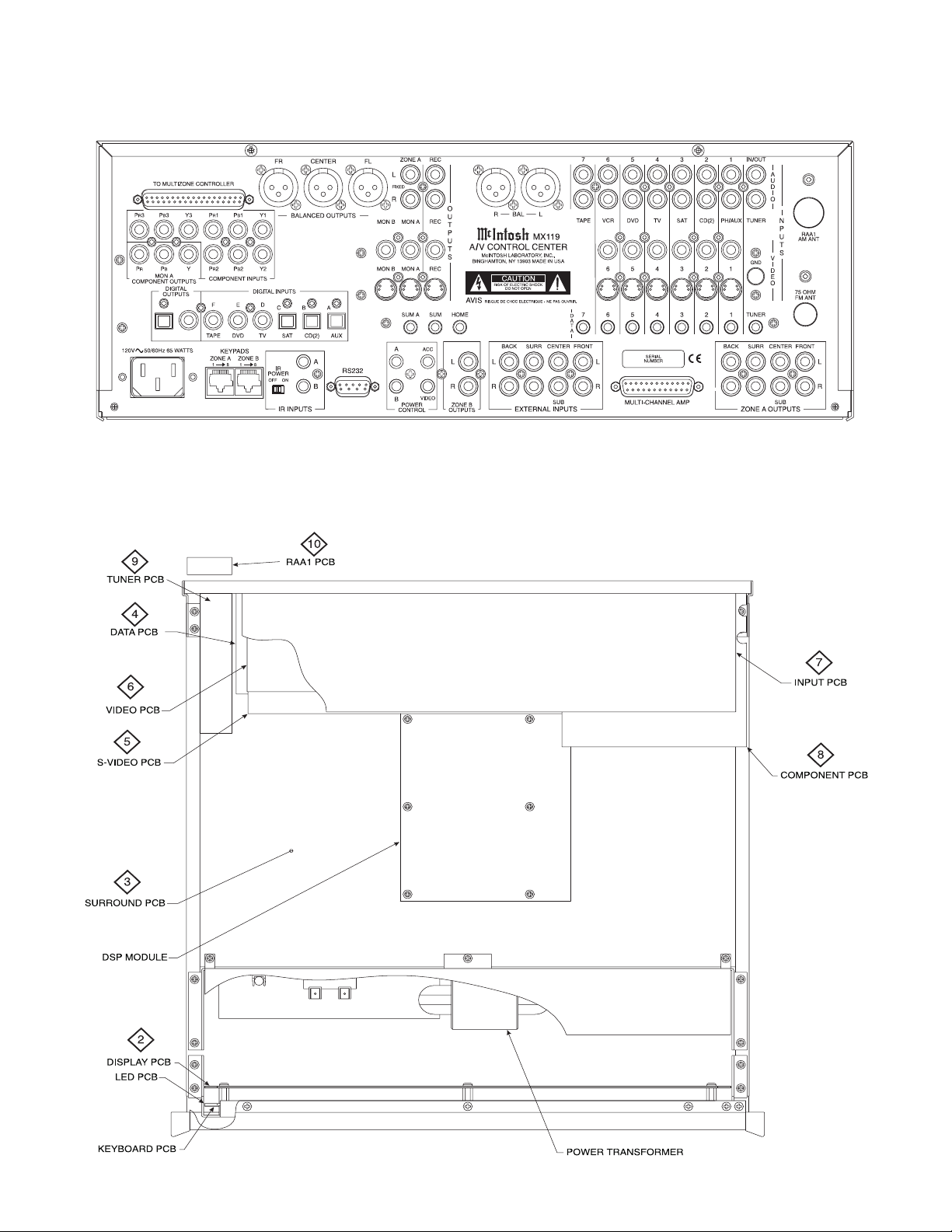
REAR PANEL
SECTION LOCATION
4
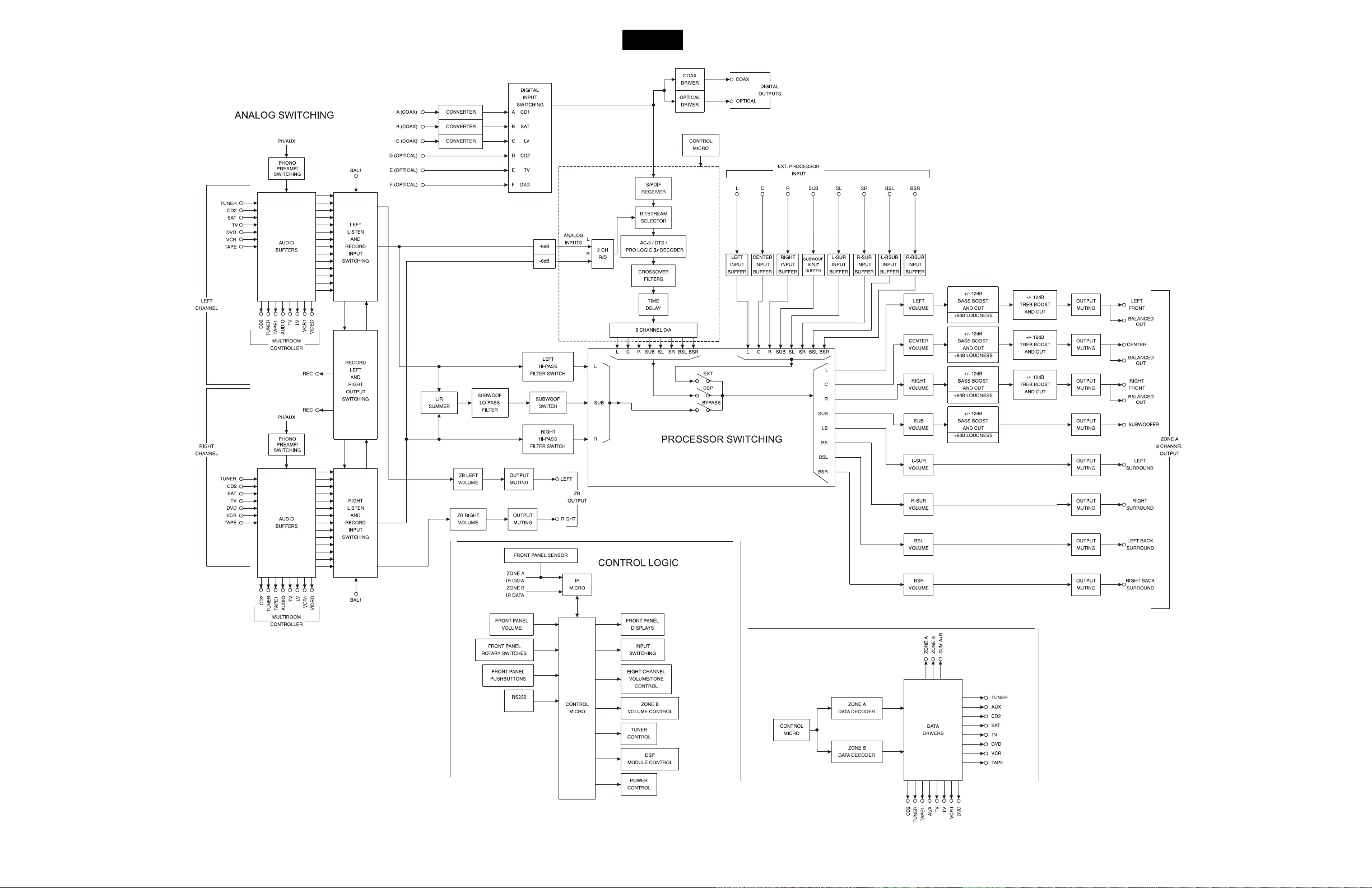
BLOCK DIAGRAM
MX119
5
6
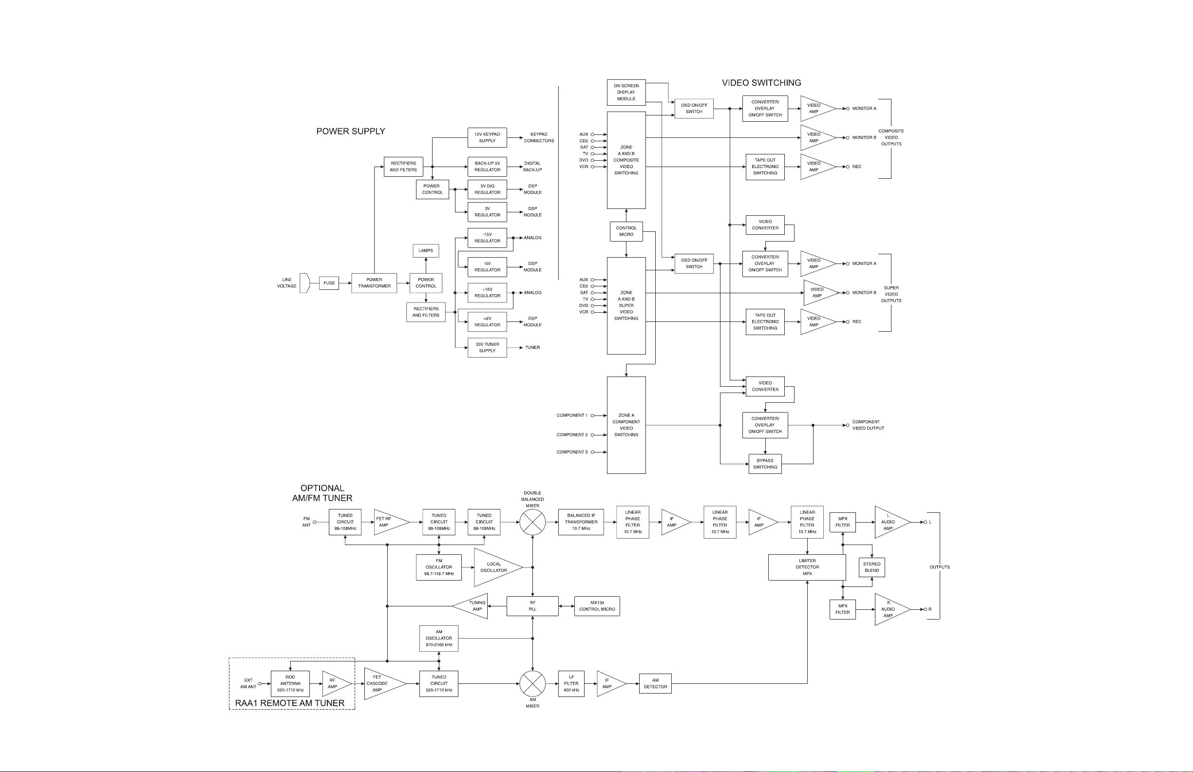
BLOCK DIAGRAM con’t
7 8
MX119
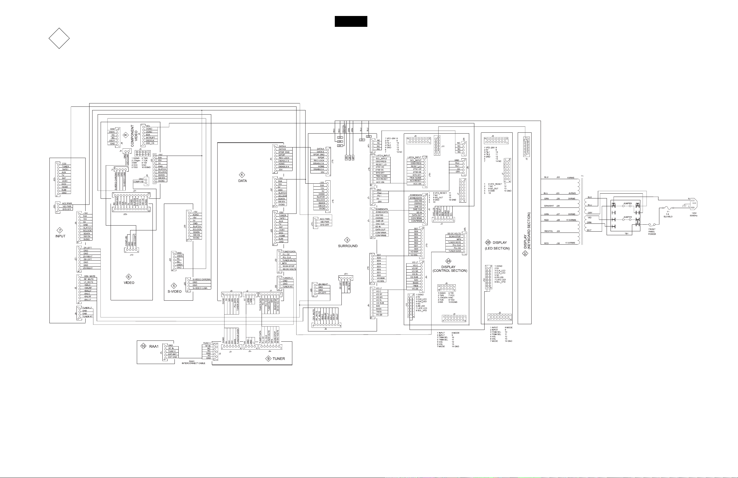
1
INTERCONNECT
9
10

2
A
C
B
DISPLAY
050167 SH 1 OF 2
11 12
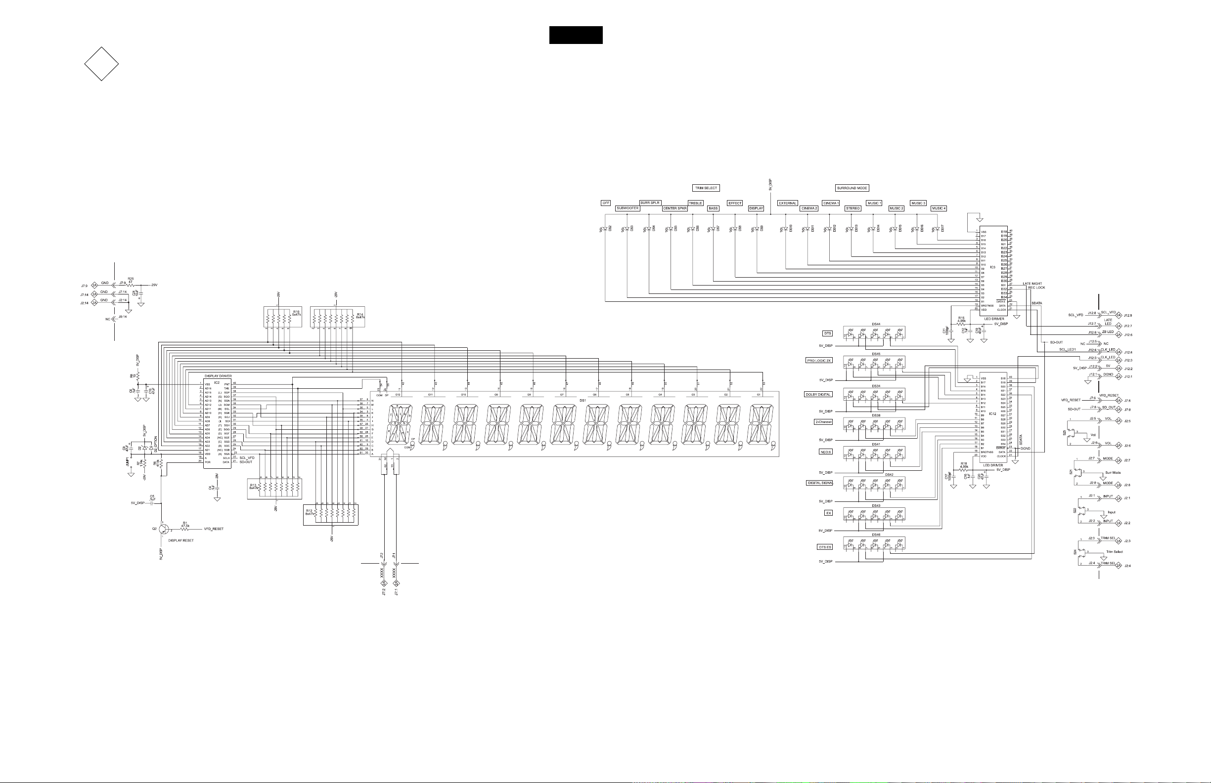
2
MX119
A
C
B
DISPLAY
050167 SH 2 0F 2
13
14
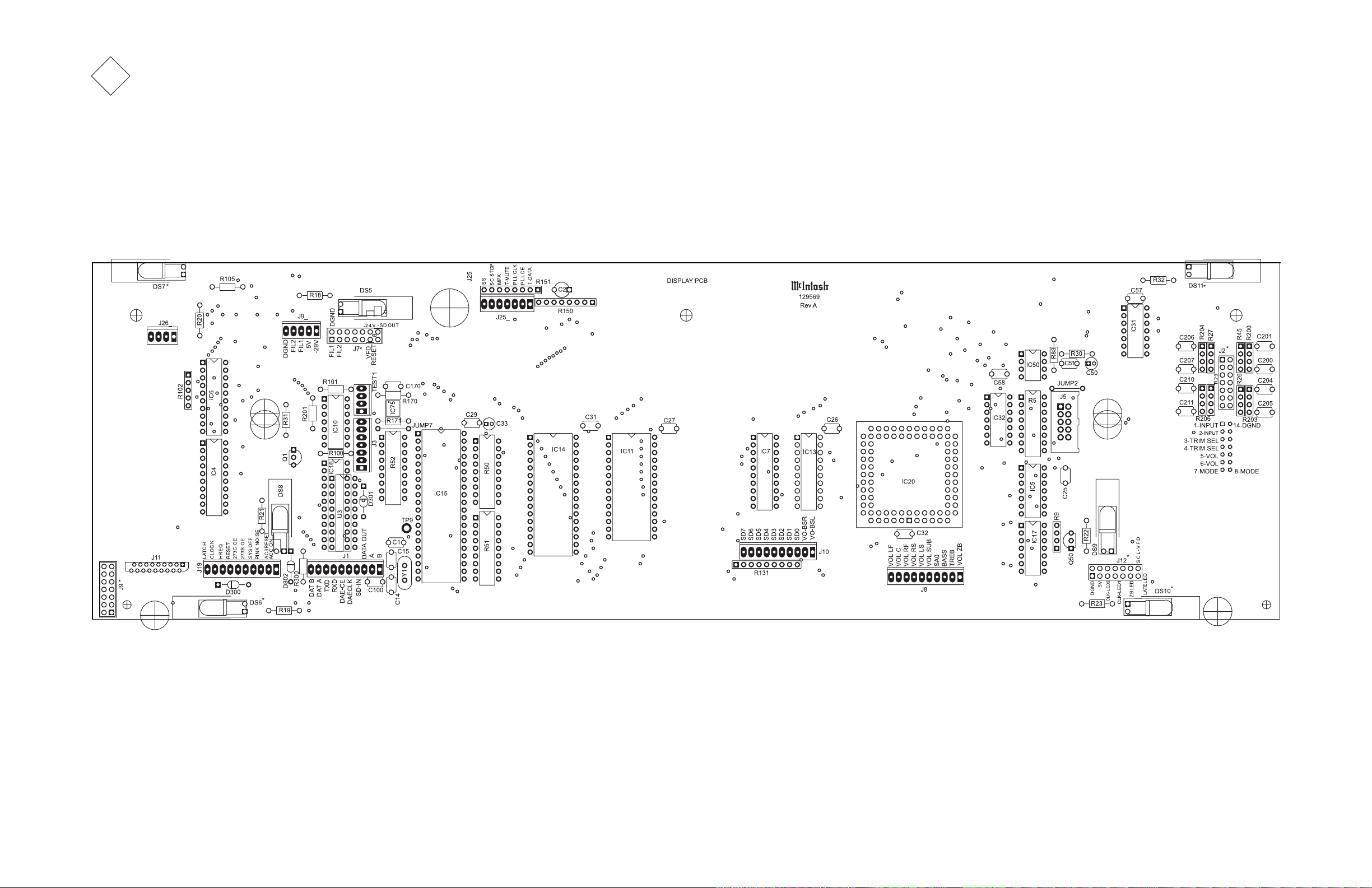
2A
DISPLAY
CONTROL SECTION
050167
15 16

MX119
2B
DISPLAY
LED SECTION 050169
2C
DISPLAY
KEYBOARD SECTION 050053
17
18
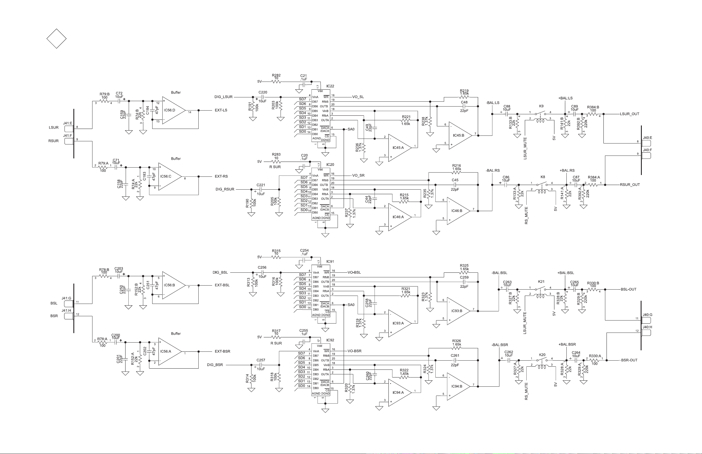
3
SURROUND
050168 SH 1 OF 6
19 20

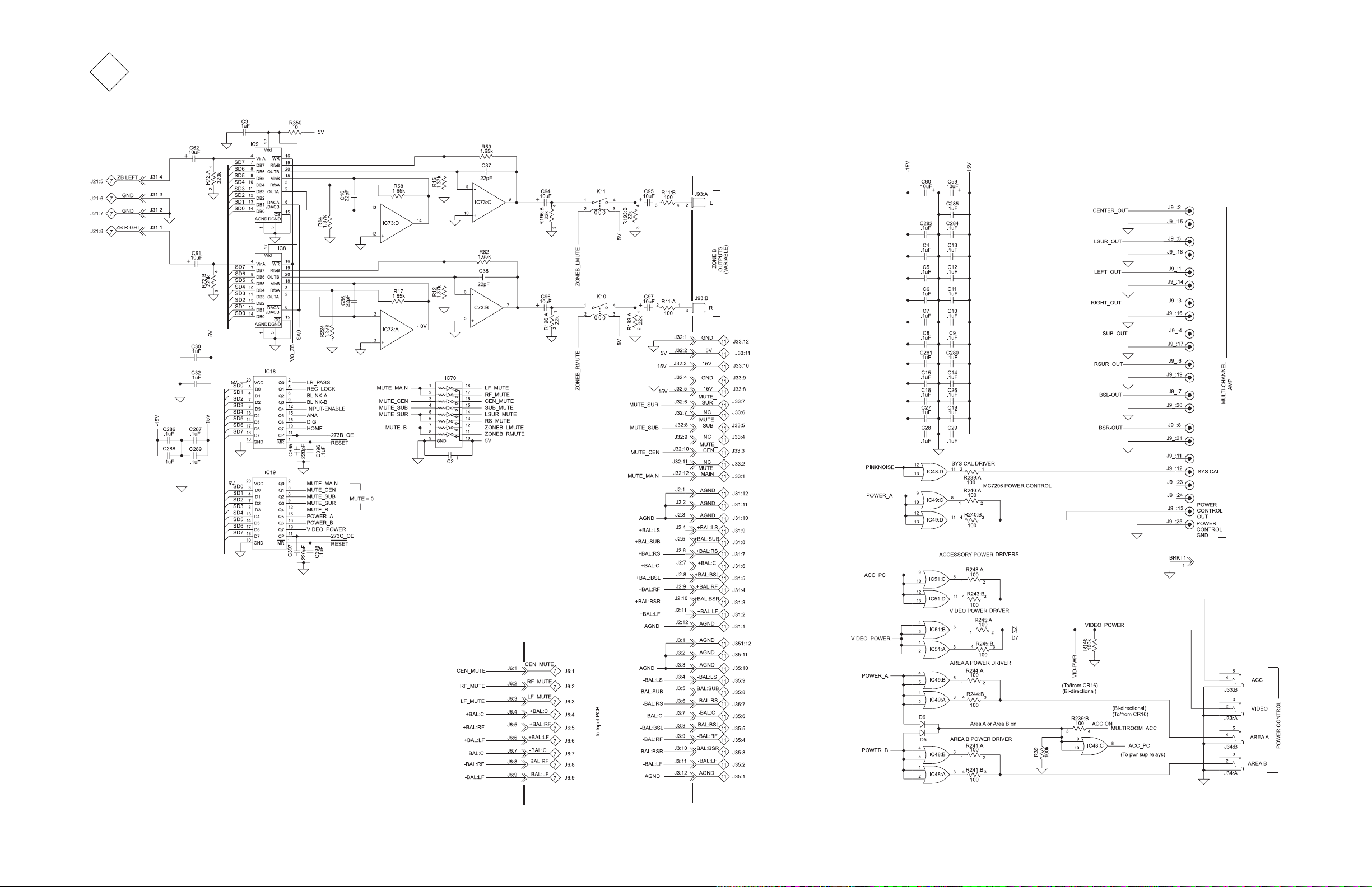
MX119
3
SURROUND
050168 SH 2 OF 6
21
22
3
SURROUND
050168 SH 3 OF 6
23 24

MX119
3
SURROUND
050168 SECTION 4 OF 6
25 26

3
SURROUND
050168 SH 5 OF 6
27 28
 Loading...