

Page 1
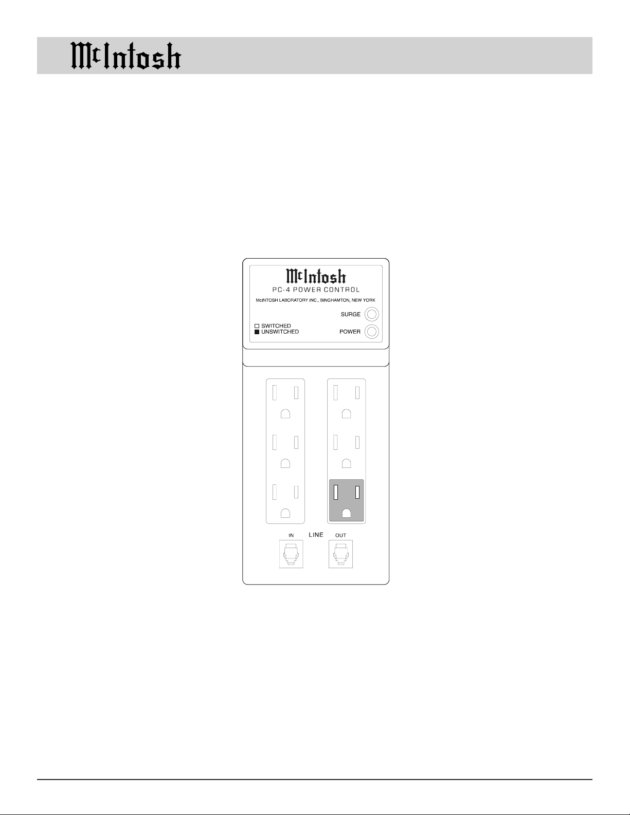
PC-4 Power Control
OWNERS
MANUAL
PC-4
McIntosh Laboratory, Inc. 2 Chambers Street Binghamton, New York 13903-2699 Phone: 607-723-3512 FAX: 607-724-0549
Page 2

Thank You, Please Take A Moment, Technical Assistance,
Customer Service, Table of Contents and Notes
Thank You Table of Contents
Your decision to own this McIntosh PC-4 Power Control
ranks you at the very top among discriminating music listeners. You now have The Best. The McIntosh dedication
to Quality, is assurance that you will receive many years
of enjoyment from this unit.
Please take a short time to read the information in this
manual. We want you to be as familiar as possible with all
the features and functions of your new McIntosh.
Please Take A Moment
The purchase date and McIntosh dealer name are important
to you for possible insurance claim or future service. The
spaces below have been provided for you to record that information:
Thank You.......................................................................... 2
Please Take a Moment ....................................................... 2
Customer Service............................................................... 2
Table of Contents ............................................................... 2
Notes .................................................................................. 2
Safety Instructions ............................................................. 3
Introduction ....................................................................... 4
Performance Features ........................................................ 4
Installation ......................................................................... 4
Front Panel Connections,
End Panel Push-Button and Connections .......................... 5
How to Connect ................................................................. 6
Important Operating Instructions ...................................... 7
Specifications .................................................................... 7
Purchase Date:
Dealer Name:
Technical Assistance
If at any time you have questions about your McIntosh
product, contact your McIntosh dealer who is familiar with
your McIntosh equipment and any other brands that may
be part of your system. If you or your dealer wish additional help concerning a suspected problem, you can receive technical assistance for all McIntosh products at:
McIntosh Sales Corporation
661 W. Redondo Beach Blvd.
Gardena, CA 90247
Phone: 888-979-3737
Fax: 310-217-9288
Customer Service
If it is determined that your McIntosh product is in need of
repair, you can return it to your dealer. You can also return
it to the McIntosh Laboratory Service Repair department.
For assistance on factory repair return procedure, contact
the McIntosh Repair Department at:
Notes
1. Connecting Cables are available from the McIntosh Parts
Department:
Power Control Cable Part No. 170-202
Six foot, shielded 2 conductor, with 1/8 inch stereo mini
phone plugs on each end.
2. For additional connection information, refer to the owners
manual(s) for any component(s) connected to the PC-4 Power
Control.
McIntosh Laboratory, Inc.
2 Chambers Street
Binghamton, New York 13903
Phone: 607-723-3515
Fax: 607-723-1917
Copyright 1998 by McIntosh Laboratory, Inc.
2
Page 3
IMPORTANT SAFETY
INSTRUCTIONS!
PLEASE READ THEM BEFORE
OPERATING THIS EQUIPMENT.
WARNING SHOCK HAZARD DO NOT OPEN.
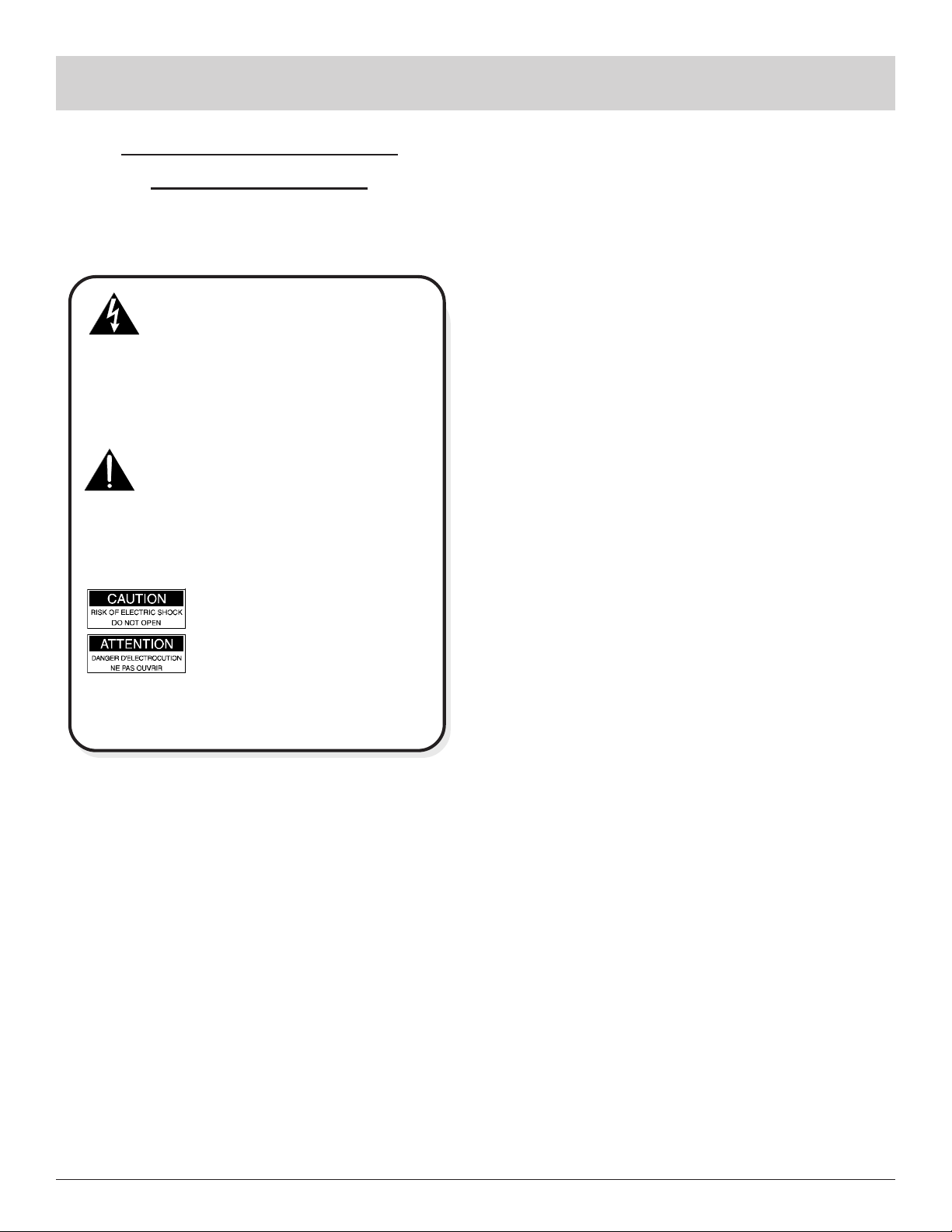
The lightning flash with arrowhead, within an equilateral
triangle, is intended to alert the user to the presence of
uninsulated dangerous voltage within the products
enclosure that may be of sufficient magnitude to consti-
tute a risk of electric shock to persons
AVIS RISQUE DE CHOC NE PAS OUVRIR.
The exclamation point within an equilateral triangle is
intended to alert the user to the presence of important
operating and maintenance (servicing) instructions in
the literature accompanying the appliance.
NO USER-SERVICEABLE
PARTS INSIDE. REFER
SERVICING TO
QUALIFIED PERSONNEL
To prevent the risk of electric shock, do not remove
cover (or back). No user serviceable parts inside. Refer
servicing to qualified personnel.
.
Safety Instructions
Installation:
7. Locate the equipment away from heat sources such as
radiators, heat registers, stoves, or other appliance that
produce heat.
8. Mount the equipment in a wall or cabinet only as de-
scribed in this owners manual
9. Do not use this equipment near water; for example, near
a bathtub, washbowl, kitchen sink, laundry tub, in a
wet basement or near a swimming pool, etc.
Connection:
10. Connect this equipment only to the type of AC power
source as marked on the unit.
11. Route AC power cords so that they are not likely to be
walked on or pinched by items placed upon or against
them, paying particular attention to cords at plugs, convenience receptacles, and the point where they exit
from the instrument.
12. Do not defeat the inherent design features of the polar-
ized plug. Non-polarized line cord adapters will defeat
the safety provided by the polarized AC plug. If the
plug should fail to fit, contact your electrician to replace your obsolete outlet. Do not defeat the safety
purpose of the grounding-type plug.
13. Do not overload wall outlets, extension cords or inte-
gral convenience receptacles as this can result in a risk
of fire or electric shock.
General:
1. Read all the safety and operating instructions, contained in this owners manual, before operating this
equipment.
2. Retain this owners manual for future reference about
safety and operating instructions.
3. Adhere to all warnings and operating instructions.
4. Follow all operating and use instructions.
5. Warning: To reduce risk of fire or electrical shock,
do not expose this equipment to rain or moisture.
6. Caution: to prevent electrical shock do not use this
(polarized) plug with an extension cord, receptacle
or other outlet unless the blades can be fully inserted to prevent blade exposure.
Attention: pour pevenir les chocs elecriques pas
utiliser cette fiche polarisee avec un prolongateur,
une prise de courant ou un autre sortie de courant,
sauf si les lames peuvent etre inserees afond ans en
laisser aucune partie a decouvert.
Care of Equipment:
14. Clean the instrument by dusting with a dry cloth. Unplug this equipment from the wall outlet and clean the
panel with a cloth moistened with a window cleaner.
Do not use liquid cleaners or aerosol cleaners.
15. Do not permit objects of any kind to be pushed and/or
fall into the equipment through enclosure openings.
Never spill liquids into the equipment through enclosure openings.
16. Unplug the power cord from the AC power outlet
when left unused for a long period of time.
Repair of Equipment:
17. Unplug this equipment from the wall outlet and refer
servicing to a qualified service personnel under the following conditions:
A. The AC power cord or the plug has been damaged.
B. Objects have fallen, or liquid has been spilled into
the equipment.
3
Page 4
Safety Instructions, Introduction
6
6
6
6
6
6
6
6
6
6
6
6
6
6
6
6
6
6
6
6
6
6
6
6
6
6
6
6
6
6
6
6
6
6
6
6
6
6
6
6
6
6
6
6
6
6
6
6
6
6
6
6
6
6
6
6
6
6
6
6
6
6
6
6
6
6
6
6
6
6
6
6
6
6
6
6
6
6
6
and Performance Features
C. The equipment has been exposed to rain or water.
D. The equipment does not operate normally by fol-
lowing the operating instructions contained within
this owners manual.
E. The equipment has been dropped or damaged in any
way.
F. The equipment exhibits a distinct change in perfor-
mance - this indicates a need for service.
18. Do not attempt to service beyond that described in the
operating instructions. All other service should be referred to qualified service personnel.
19. When replacement parts are required, be sure the service technician has used replacement parts specified by
McIntosh or have the same characteristics as the original part. Unauthorized substitutions may result in fire,
electric shock, or other hazards.
20. Upon completion of any service or repairs to this product, ask the service technician to perform safety checks
to determine that the product is in proper operating
condition.
Introduction
The McIntosh PC-4 Power Control provides automatic
heavy duty power control of McIntosh Components in a
system.
Performance Features
Switched Accessory Outlets
These outlets will turn on whenever the system turns on
and can be used to supply power to accessory audio components.
Unswitched Outlet
The unswitched outlet stays on as long as the main PC-4
power cord is plugged into a live AC outlet.
Built-in Spike Protector
Components connected to the PC-4 are protected from potentially damaging line voltage spikes.
Telephone Protection
An Input and Output are provided to connect a telephone
so it is protected from damaging voltage spikes.
LED Indicators
A Red LED indicates when the switched outlets are on, and
Green LED indicates Transient Protection Status.
4
Installation
The PC-4 can be placed on a table or shelf. Cool operation
ensures the longest possible operating life for any electronic instrument. Do not install the PC-4 directly above a
heat generating component such as a high powered amplifier. Consideration should be give to allow for easy access
of the PC-4 for connection of the AC Power Cords coming
from other components.
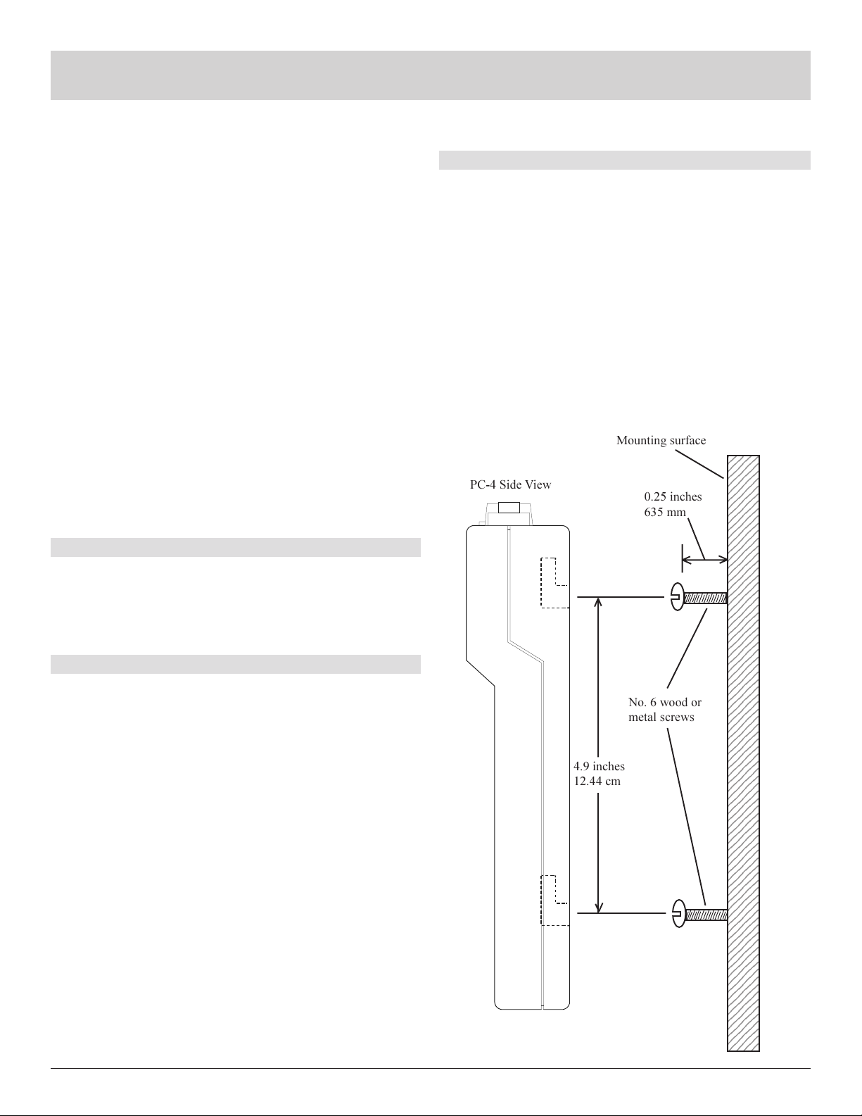
The PC-4 can be secured to a wall, shelf or cabinet by
hooking its back panel slots over the heads of two No. 6
wood screws or metal screws. The mounting centers for the
screws or bolts should correspond to the spacing of the
slots. Allow approximately 0.25 inches of the screw to extend out in order to allow the PC-4 back panel slots to fit
over the screw heads.
Mounting surface
2345
2345
2345
PC-4 Side View
0.25 inches
635 mm
No. 6 wood or
metal screws
4.9 inches
12.44 cm
2345
2345
2345
2345
2345
2345
2345
2345
2345
2345
2345
2345
2345
2345
2345
2345
2345
2345
2345
2345
2345
2345
2345
2345
2345
2345
2345
2345
2345
2345
2345
2345
2345
2345
2345
2345
2345
2345
2345
2345
2345
2345
2345
2345
2345
2345
2345
2345
2345
2345
2345
2345
2345
2345
2345
2345
2345
2345
2345
2345
2345
2345
2345
2345
2345
2345
2345
2345
2345
2345
2345
2345
2345
2345
2345
2345
Page 5
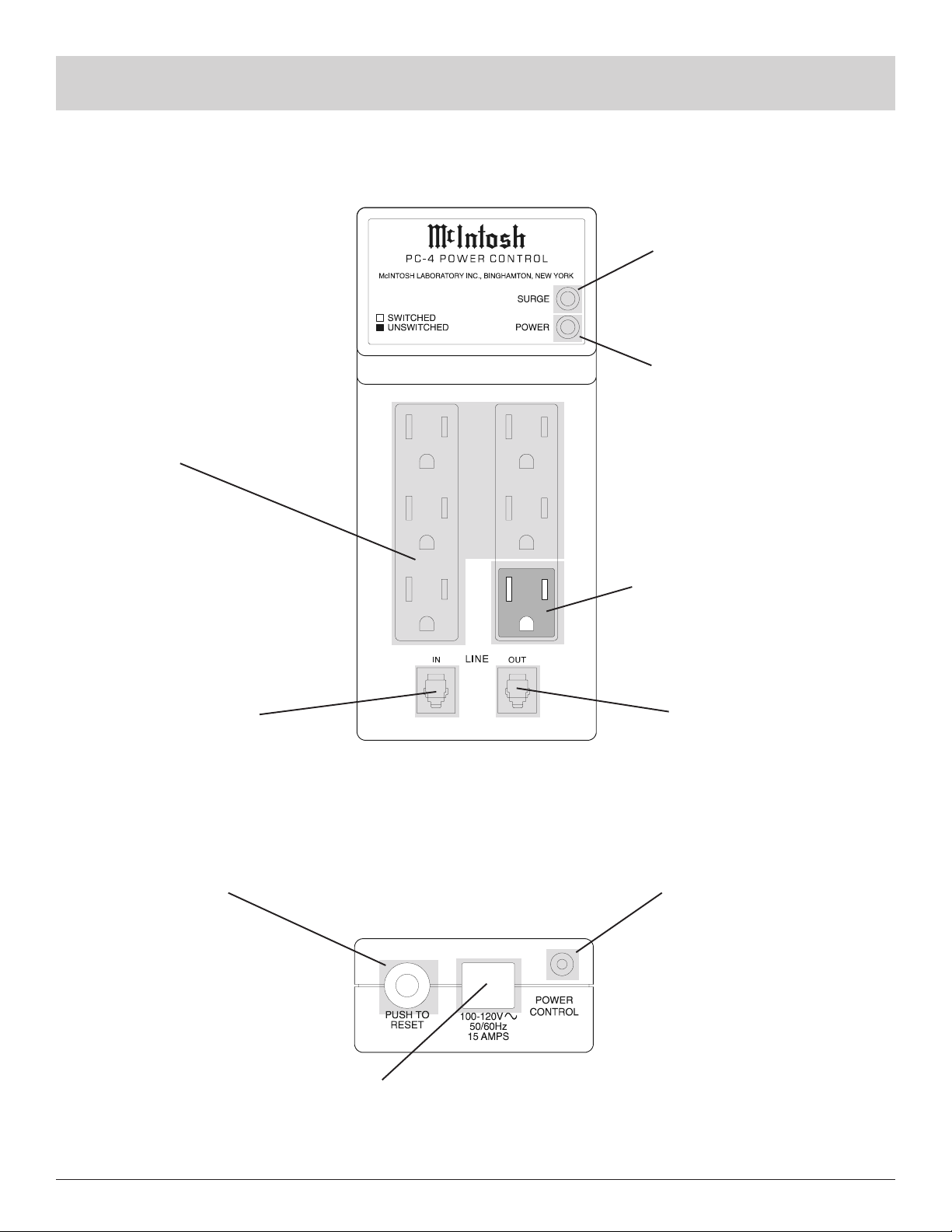
SWITCHED outlets for
system accessory components
Front Panel Connections and Display
End Panel Push-Button and Connections
LED that indicates when the
PC-4 Transient Suppression
Circuity is active
LED that indicates when the
switched outlets are on
LINE IN connection for
incoming telephone line
RESET resets the internal circuit
breaker in the event that it was
tripped by a current overload
from a connected component
UNSWITCHED outlet remains
on as long as the PC-4 power
cord is plugged into a live AC
outlet
LINE OUT connection for
telephone
POWER CONTROL connects to
a McIntosh Preamplifier, Control
Center, Integrated Amplifier or
Multizone System Controller
AC POWER CORD plugs into a live
AC outlet. Refer to information on the
end panel of your PC-4 to determine
the correct voltage for your unit
5
Page 6
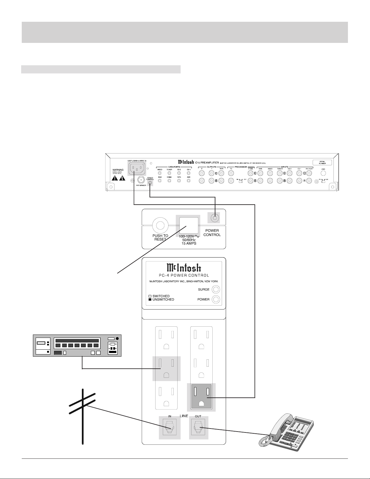
How to Connect
1. Connect the PC-4 Power Cord to a live AC outlet that is
capable of supplying 15 amperes at 100-120 volts.
2. Connect a Power Cable from a McIntosh Preamplifier,
Control Center, Integrated Amplifier or Multizone System Controller to the PC-4 unswitched AC outlet.
3. Connect accessory component power cords to the
switched PC-4 AC outlets.
How to Connect
4. Connect a Power Control cable from a McIntosh
Preamplifier, Control Center, Integrated Amplifier or
Multizone System Controller Out jack to the PC-4
POWER CONTROL jack.
5. Connect LINE IN to incoming telephone line and the
LINE OUT to the telephone.
McIntosh Preamplifier
AC POWER CORD plugs
into a live AC outlet. Refer
to information on the side
panel of your PC-4 to determine the correct voltage for
your unit
Tape Recorder
6
Page 7

Important Operation Information
Unswitched AC Outlet
The unswitched outlet stays on as long as the PC-4 main
power cord is connected to a live outlet and is to be used
for a component that needs AC power at all times such as a
McIntosh Preamplifier, Integrated Amplifier, Control Center or Multizone System Controller.
Switched AC Outlet
When a McIntosh Preamplifier, Integrated Amplifier, Control Center or Multizone System Controller turns on, the
PC-4 Switched AC outlets will also turn on.
Important Operation Information
and Specifications
Power Control
Connect a shielded control cable with 1/8 inch mini phone
plugs on each end to the Power Control Out of a McIntosh component. When the component turns on, a control
signal is sent to the PC-4 that will turn on the Switched
AC outlets.
Specifications
Power Capacity
100-120 Volts, 50/60Hz 15 Amps
Telephone Protection
When an incoming telephone line and a telephone are connected to the PC-4 Line jacks, the telephone is protected
from potentially damaging line voltage spikes.
LED Indicators
The green Surge LED will stay on continuously to indicate
that the spike protection circuits are still active. If this LED
does not light, the protection circuits may have been damaged, and you should immediately contact your McIntosh
dealer for assistance. The RED lights whenever the
Switched outlets are live. Refer to Figure one.
Power Requirements
100-120 Volts, 50/60Hz at 5 watts
Dimensions
1.6 inches (4.06cm) Wide, 1.25 inches (3.18cm) High, 7.38
inches (18.75cm) depth
Weight
1.15 pounds (522g) net, 3 pounds (1.36Kg) shipping
Figure 1
Circuit Breaker
The circuit breaker provides protection against a current
overload from a component connected to any of the PC-4
outlets. Reset by pressing in on the breaker pushbutton, located on the end panel.
7
Page 8

McIntosh Laboratory, Inc.
2 Chambers Street
Binghamton, NY 13903
McIntosh Part No. 040622
 Loading...