

Page 1
Contents
SERVICE CONTRACT INFORMATION 1
INTRODUCTION 2
INSTALLATION 3, 4
BACK PANEL CONNECTIONS
USING THE FRONT PANEL
HOW THE CIRCUITS WORK 9, 10
PERFORMANCE CHARTS. . . .12, 13
AND CONTROLS 5, 6
CONTROLS 7, 8
PERFORMANCE LIMITS 11
BLOCK DIAGRAM 14
FM STATION LOG 15
The Mclntosh compact Family
TUNER
FM
DIGITAL
MR 500
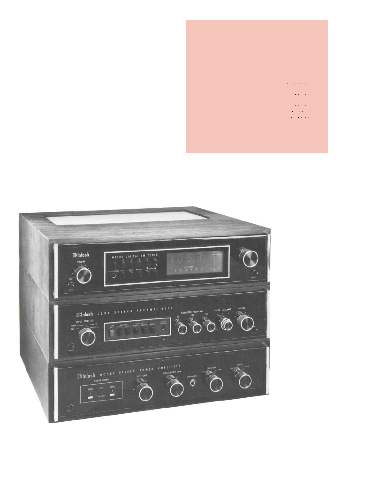
The MR 500 Digital FM Tuner complements the performance and appearance of all Mclntosh products. It
is specifically designed to match the industry's
leading compacts — the Mclntosh MC 502 Power Amplifier and the Mclntosh C 504 Preamplifier. Separate,
flexibile Mclntosh quality components that are particularly useful where space is limited.
1
Page 2

The MR 500 FM Tuner is designed to
perform to its specifications for many
years. If you have any questions, please
contact:
CUSTOMER SERVICE
Mclntosh Laboratory Inc.
2 Chambers Street
Binghamton, New York 13903-9990
Phone: 607-723-3512
Take Advantage of 3 years of
Contract Service...
Fill in the Application NOW.
MclNTOSH THREE YEAR SERVICE CONTRACT
An application for A THREE YEAR SERVICE CONTRACT is included with this manual.
The terms of the contract are:
1. Mclntosh will provide all parts, materials
and labor needed to return the measured
performance of the instrument to the
original performance limits. Because
battery life is dependent on conditions
over which Mclntosh has no control,
they are not covered under the service
contract, nor is any shipping cost to and
from the authorized service agency or
the factory.
2. Any Mclntosh authorized service agency
will repair Mclntosh instruments at nor-
mal service rates. To receive service
under the terms of the SERVICE CONTRACT, the SERVICE CONTRACT CERTIFICATE must be presented when the
instrument is taken to the service agency.
3. Always have service done by a
Mclntosh authorized service agency. If
the instrument is modified or damaged
as a result of unauthorized repair, the
SERVICE CONTRACT will be cancelled.
Damage by improper use or mishandling is not covered by the SERVICE
CONTRACT.
4. The SERVICE CONTRACT is issued to
you as the original purchaser. To pro-
tect you from misrepresentation, this
contract cannot be transferred to a second owner.
5. To receive the SERVICE CONTRACT,
your purchase must be made from a
Mclntosh franchised dealer.
6. Your completely filled in application for
the SERVICE CONTRACT must be postmarked within 30 days of the date of
purchase of the instrument.
7. To receive the SERVICE CONTRACT, all
information on the application must be
filled in. The SERVICE CONTRACT will
be issued when the completely filled in
application is received by Mclntosh
Laboratory Incorporated in Binghamton,
New York.
8. Units in operation outside the United
States and Canada are not covered by
the Mclntosh Service Contract, irrespective of the place of purchase. Nor
are units acquired outside the U.S.A.
and Canada, the purchasers of which
should consult with their dealer to
ascertain what, if any, service contract
or warranty may be available locally.
Copyright 1983 (C) by Mclntosh Laboratory Inc.
2
Page 3
Installation
any position. The recommended minimum space for
adequate ventilation is 17 inches (43.2 cm) wide, and 4
1/2inches (11.4 cm) high, 15 inches (38.1 cm) deep.
To install the instrument in a Mclntosh cabinet,
follow the instructions that are enclosed with the
cabinet. For any other type of installation follow
these instructions:
1. Unpack from carton
Open the carton and remove the PANLOC brack-
ets, hardware package, and mounting template from
the carton. Remove the MR 500 from its plastic bag
and place it upside down on the shipping pallet;
then unscrew the four plastic feet from the bottom
of the chassis.
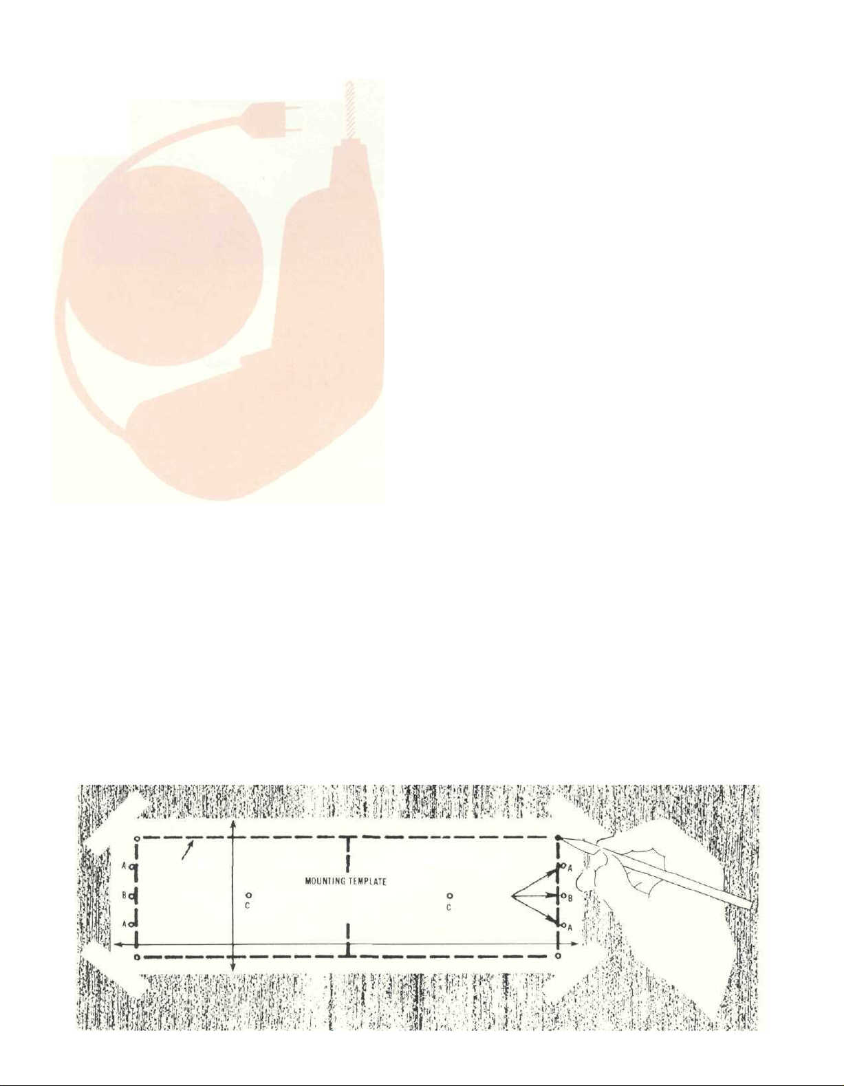
2. Mark the cabinet panel
Place the mounting template in the position on
the cabinet panel where the instrument is to be in-
stalled, and tape it in place. The broken lines that
represent the outline of the rectangular cutout also
represent the outside dimensions of the chassis.
Make sure these lines clear shelves, partitions, or
any equipment. With the template in place, first
mark the six A and B holes and the four small holes
that locate the corners of the cutout. Then, join the
four corner markings with pencil lines, using the
edge of the template as a straigtedge.
The PANLOC system of installing equipment
conveniently and securely is a product of Mclntosh
research. By depressing the two PANLOC buttons on
the front panel, the instrument can be either locked
firmly in place or it can be unlocked so that the
chassis can slide forward, giving you easy access to
the top and rear panels.
The trouble-free life of an electronic instrument is
greatly extended by providing sufficient ventilation to
prevent the build-up of high internal temperatures that
cause deterioration of component parts. You should allow enough clearance so that cool air can enter at the
bottom of the cabinet and be vented from the top. With
adequate ventilation the instrument can be mounted in
3. Drill Holes
Use a drill with a 3/16 inch (5 mm) bit held perpen-
dicular to the panel and drill the six A and B holes.
Then, using a drill bit slightly larger than the tip of
your saw blade, drill one hole at each of two
diagonally opposite corners. The holes should barely touch the inside edge of the penciled outline.
Before taking the next step, make sure that the six A
and B holes have been drilled.
4. Saw the Panel Cutout
Saw carefully on the inside of the penciled lines.
First make the two long cuts and then the two short
cuts. After the rectangular open ing has been cut out,
use a file to square the corners and smooth any
irregularities in the cut edges.
3
Page 4
5. Install the Mounting Strips
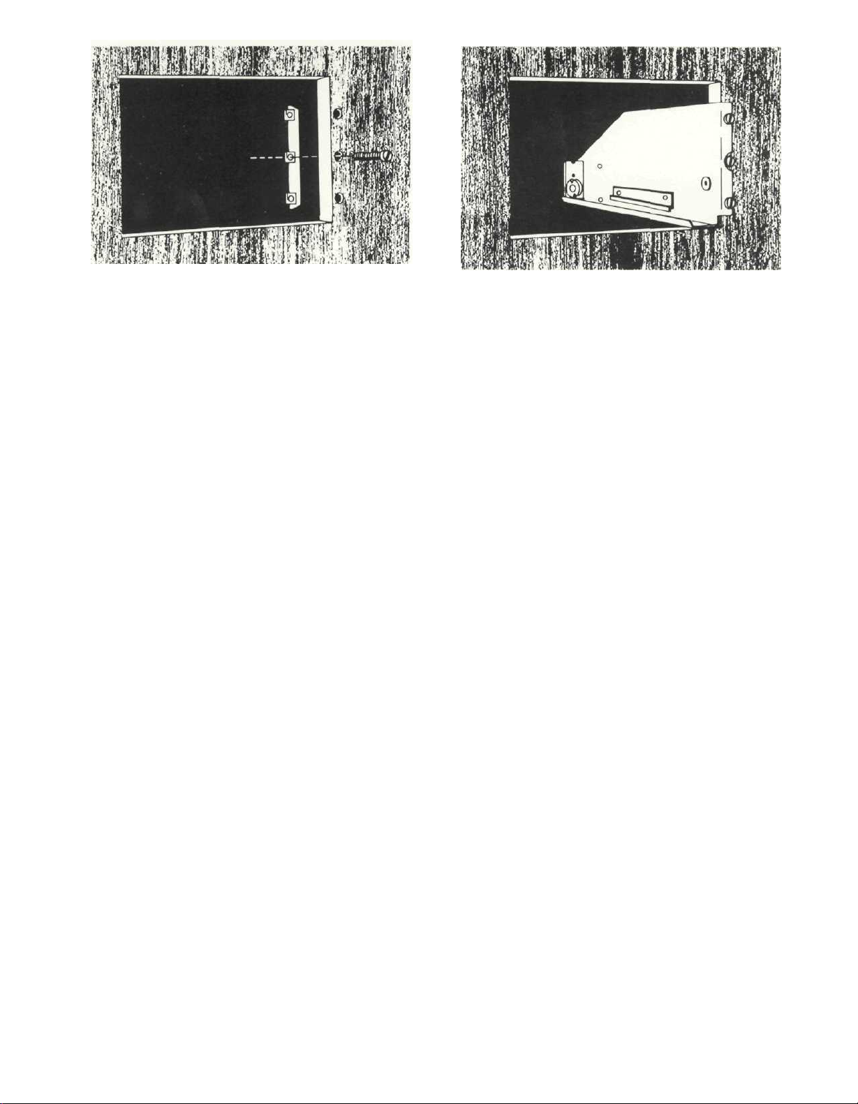
In the hardware package you will find two mount-
ing strips and two sets of machine screws. For
panels that are less than 1/2 inch (12.7 mm) thick,
use the 3/4 inch (19.1 mm) screws; for panels that are
more than 1/2 inch (12.7 mm) thick, use the 1 1/4 inch
(31,8 mm) screws.
Starting at the right-hand side of the panel, insert
a screw of proper length into the center hole in the
panel, marked B on the template. On the back of the
panel, align a mounting strip with the holes in the
panel and tighten the screw in the center hole until
the screwhead is pulled slightly into the wood.
Repeat this procedure to attach the mounting
strip to the left side of the panel.
6. Attach the PANLOC Brackets
Use two screws of the proper length in the A holes
on each side, attach the PANLOC brackets to the
cabinet panel; the short flange is mounted against
the front (face) of the cabinet panel. The screws
pass through the PANLOC bracket flange, the
cabinet panel, and then through the mounting strips
previously mounted.
7. Install the Instrument
Guide the AC power cord through the panel open-
ing to the back of the cabinet. Then, slide the instru-
ment into the opening, carefully, so that the rails on
the bottom of each side of the chassis engage the
tracks on the mounting brackets. Continue to slide
the instrument into the cabinet until it is stopped by
the adjust position latches. Press the latches inward, this permits the instrument to slide into the
cabinet until its front panel is flush with the cabinet
panel. Depress the PANLOC buttons at the lower left
and right corners of the instrument panel to lock the
unit firmly in the cabinet. Depressing the PANLOC
buttons again will unlock the instrument so that it
can slide to the adjust position; if you press inward
on the adjust position latches then you can remove
the instrument from the cabinet.
4
Page 5

Back Panel Connections and Controls
Use of the back panel connections and controls
will be described from right to left when looking at
the back panel.
MANUAL AFL
Automatic Frequency Lock (AFL) is a Mclntosh
design which assures that the station remains ideal-
ly tuned regardless of any influences that might
cause the station to drift. Because the AFL circuit
does not affect the high quality performance of the
MR 500, the switch should be used in the NORMAL
position. There may be occasions when it would be
desirable to deactivate the AFL circuit for manual
tuning. With the MANUAL AFL switch in the OUT
position, and when using the tuning knob, the AFL
circuit is disabled. The AFL circuit is always active
when the SCAN tuning and the feather touch preset
station selection push buttons are used.
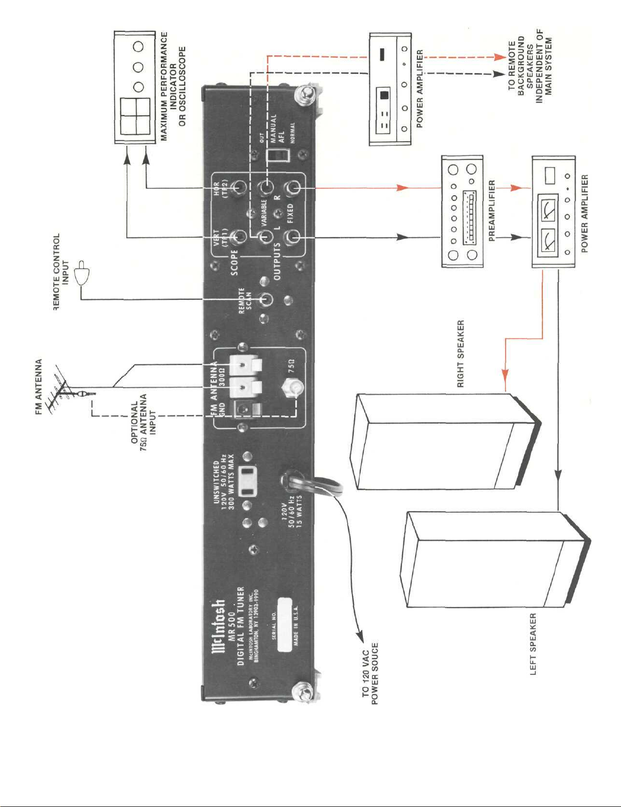
AUDIO OUTPUTS
Use the FIXED OUTPUT jacks on the rear panel to
connect the MR 500 to a stereo control preamplifier
or other equipment which has its own volume control. The position of the VOLUME control does not
affect the loudness of the tuner at the FIXED OUT-
PUT jacks. The output level is 1 volt for 100% FM
modulation.
Use the VARIABLE OUTPUT jacks to connect to
equipment such as a power amplifier or a tape
recorder where control of the volume is to be at the
tuner. With the VOLUME control turned completely
clockwise, the output at the VARIABLE OUTPUT
jacks is 2.5 volts for 100% FM modulation. There is
no difference in the signal quality at either of the
pairs of output jacks; and, both pairs may be used
simultaneously. The output impedance is very low
so that long audio cables can be used without a loss
of high frequencies due to cable capacity.
SCOPE
The vertical and horizontal SCOPE jacks are pro-
vided to connect to a maximum performance indicator or an oscilloscope which can then indicate
FM multipath and signal strength. Connect the ver-
tical jack to the vertical input of the indicator and
the horizontal jack to the horizontal input.
REMOTE SCAN
The REMOTE SCAN jack provides an input for the
cable push button assembly supplied with the
MR 500. Plug the cable into the REMOTE SCAN jack
to provide SCAN tuning at a convenient location
remote from the tuner. If REMOTE SCAN tuning is
not used, leave the jack free of any connection.
CONNECTING AN FM ANTENNA
One of three antenna systems can be used: (1) an
outdoor FM antenna, or (2) a VHF-TV antenna, or (3)
the indoor dipole supplied.
An outdoor antenna is recommended for optimum
performance in all areas. For best results in fringe
(outlying) areas, use a highly directional FM antenna
in conjunction with a rotator. If the antenna uses a
300 ohm down lead, connect it to the ANTENNA
300ohm
reception can be effective. Connect the down lead
from the VHF-TV antenna to the ANTENNA 30012 FM
push connectors.
na connects to the rear panel ANTENNA 75ohm FM
type F coaxial connector.
antenna for use in urban or high strength signal
areas. Connect it to the ANTENNA 300ohm FM push
connector. The flexibility of the twin flat wire
assembly permits it to be placed under a rug, tacked
behind the stereo or placed in any other convenient
location. In some cases, it may be necessary to
"position" the antenna for best signal reception. Do
this before it is permanently located. Avoid locating
the antenna next to other wires or metal objects. Any
indoor antenna may be ineffective in houses having
metal siding or metal foil insulation.
120V AC OUTLET
watts available for additional equipment that has its
own AC power switch. The outlet is not fused.
AC POWER CORD
Hz power line receptacle. The power used by the
MR 500 is 15 watts.
FM
push connectors.
A VHF-TV antenna designed for both FM and TV
The coaxial cable of an unbalanced 75 ohm anten-
Supplied with the tuner is a flexible folded dipole
Provides a 120 volt AC power outlet with up to 300
Connect the AC power cord to a 120 volt, 50 to 60
5
Page 6
6
Page 7
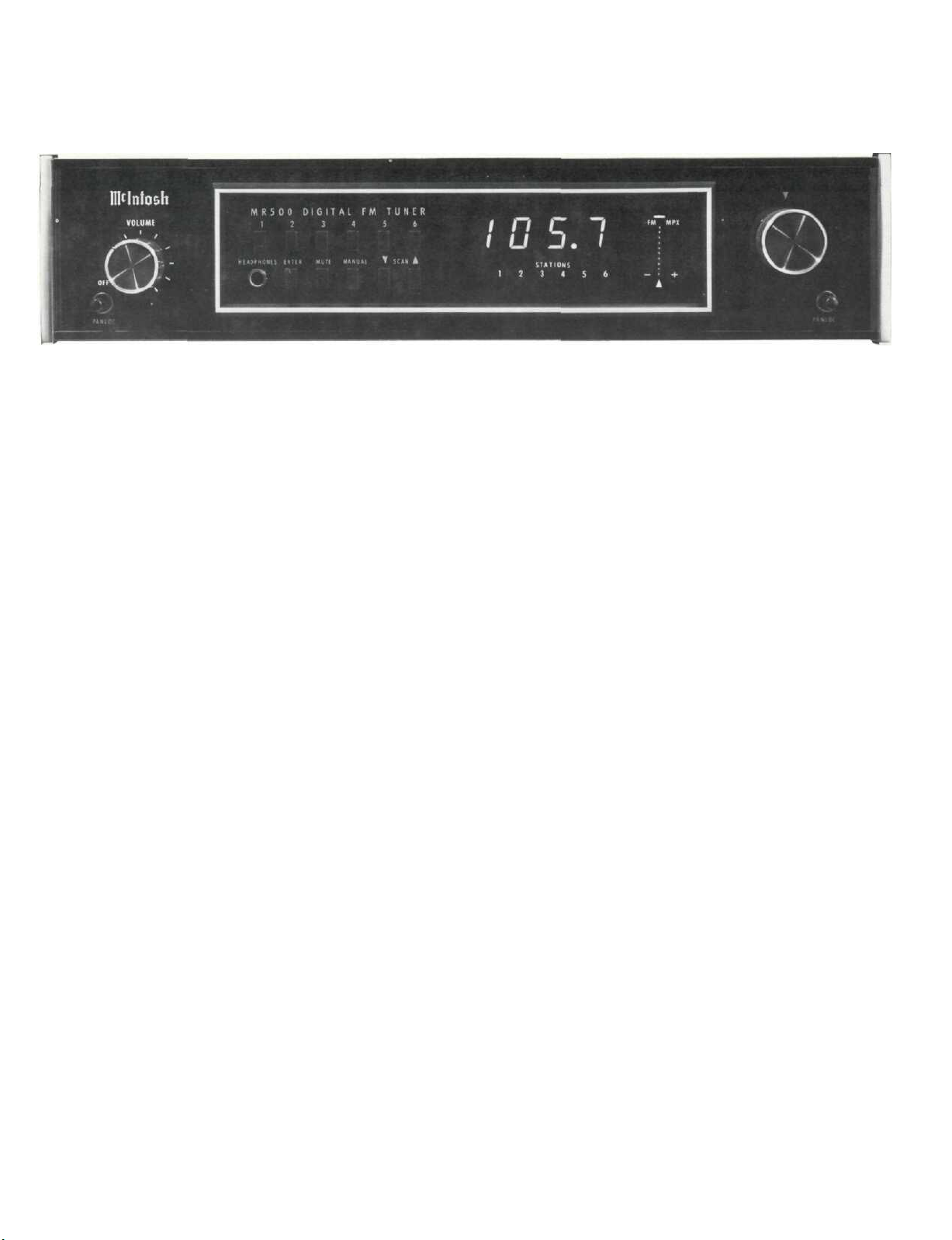
Using the Front Panel Controls
On the front panel of the MR 500 there are: volume
control with tuner on/off AC power switch, 6 momentary feather touch push buttons for selecting preset
stations, a jack for headphone listening, 1 on/off
push button for between station noise muting, 4
momentary tuning assistance feather touch push
buttons, a digital frequency display, 6 preset station
indicators, an all solid state tuning indicator and the
manual tuning knob and indicator.
VOLUME CONTROL WITH AC POWER SWITCH
The VOLUME control has been precision tracked
troughout the listening range (0 to -65 dB) for accurate stereo balance. The AC power switch is part
of the VOLUME control. The output level of the
VARIABLE OUTPUT jacks and the front panel HEADPHONE jack is controlled by the VOLUME control.
The FIXED OUTPUT jacks are not affected by the
position of the VOLUME control except when the
VOLUME control is turned fully counterclockwise
the AC power is turned off.
PRESET STATION SELECTING
'FEATHER TOUCH' PUSH BUTTONS
A momentary press on one of the push buttons
marked 1 thru 6 will recall from the electronic
memory the pre-set station assigned to that push
button, the corresponding indicator under the digital
frequency display will light and the station will be
tuned to the exact center of the channel. AFL is then
applied and precise tuning is maintained.
HEADPHONE JACK
A HEADPHONE jack is provided to drive low impedance dynamic headphones from an internal
stereo power amplifier.
ENTER
The ENTER push button and one of the six momen-
ary feather touch push buttons are used to insert into
the electronic memory the desired tuned station. Sta-
tions can be selected for insertion in the electronic
memory by use of either the manual tuning knob or
SCAN tuning. To enter a station in the memory, tune to
the desired station with the manual tuning knob, or the
SCAN tuning. Then, while pressing the ENTER push
button press one of the upper row, numbered push buttons. Release both push buttons and the station tuning
is recorded in the electronic memory for instantaneous
recall. Because the memory is retained when the
MR 500 is turned off, upon turn on it will operate in the
same mode of operation and station tuning as when
turned off.
THE ELECTRONIC MEMORY
CHARGING BATTERY POWER SUPPLY
A very long life, rechargeable battery power supply provides the energy for the electronic memory
when the tuner is turned off. When the tuner is first
connected it is wise to assume that the batteries
have not been charged. The charge rate is dictated
by the 'on' time of the tuner. To bring the batteries to
full charge, operate the tuner for twenty four continuous hours. When fully charged, the tuner will retain the programmed instructions for more than six
months with the tuner turned off. After the batteries
are fully charged, using the tuner for approximately
one hour per week, will maintain the batteries in a
fully charged state. Battery life is dependent on
usage, storage, temperature and time.
Do not attempt to remove the batteries from the
MR 500. Battery replacement should only be done at
Mclntosh authorized service agencies.
MUTE
With the MUTE push button pressed to the IN
position, weak noisy stations and between station
noises are surpressed when using the manual tuning knob. Muting circuits are not active with the
MUTE push button out. Muting is always active
when using the preset station selectors and when
SCAN tuning.
MANUAL
A momentary press of the MANUAL feather touch
push button will activate the tuning knob as in-
dicated by the lighted arrow above the knob. Rotate
Page 8

the tuning knob until the frequency of the desired
station shows on the digital frequency display.
A station is correctly tuned when the center arrow
indicator at the bottom of the tuning indicator illuminates. On each side of the center arrow are arrows marked + and -, one of which will light as a
station is approached to indicate tuning above ( + )
or below (-) the center of the station. When the
center arrow lights, the station is center channel
tuned, the FM AFL (automatic frequency lock) circuit
is activated and the tuner is locked to the FM station. Mclntosh AFL will give the best FM reception
with lowest background noise, lowest distortion and
best stereo separation.
Because of the locking action of the AFL circuit,
the tuning knob can be turned, mechanically, slight-
ly away from the frequency of the station without
detuning. This makes tuning very easy but can
cause the tuner to lose the station when power is
turned off and on again. To prevent this, stop rotation of the tuning knob as soon as the center arrow
is lighted.
A momentary press on either the SCAN or preset
station push buttons deactivates the manual tuning
knob and activates the tuning method selected.
SCAN
The tuner will automatically precisely tune the
next station up or down the spectrum depending
which SCAN push button is pressed. The arrow
above the push button indicates the direction of the
scan. When the remote scan cable is inserted in the
rear panel receptacle, a momentary press of the
push button on the end of the remote scan cable will
activate the tuner scan-up circuits.
TUNING INDICATOR
Accuracy of tuning and signal strength is indicated by the 14 LED tuning indicator. At the top is
a bar which, when illuminated, indicates that the
tuned station is transmitting in stereo (MPX). The
vertical column of 10 dots shows the relative signal
strength for the received station. The greater the
number of illuminated dots the greater the station's
signal strength.
The three arrows at the bottom of the indicator
shows above (+), below (-) or exact center channel
tuning. A correctly tuned FM station will have only
the center vertical pointing arrow lighted.
8
Page 9

How the Circuits Work
TUNING SYSTEM
Todays FM electronic tuning systems can
generally be classified as either a Phase Locked
Loop (PLL) Synthesizer System or Voltage Syn-
thesizer, Signal Locked Loop System.
Mclntosh has selected the Voltage Synthesizer, a
Signal Locked Loop (SLL) System which locks the
MR 500 to the incoming signal of the FM station.
With the tuner tuned to the station frequency and
the correction voltage being generated by the detector "zero" crossing, all parts of the tuner, mixer,
local osc., IF, etc. are inside the tuning loop and accurate tuning is assured. As long as the station
transmits within the tuning range of the MR 500,
regardless of frequency, the SLL system will lock on
to the station and remain center channel tuned.
In contrast, in the PLL system, the local oscillator
frequency is compared to a reference within the
tuner, usually a crystal controlled oscillator. A com-
parison circuit generates a correction voltage to
hold the local oscillator to an exact multiple of the
reference oscillator. The frequency of the reference
oscillator must be equal to the station channel spac-
ing (200 kHz in the United States) in order to cover all
the FM channels. Tuning is accomplished in dis-
crete steps which makes it impossible to tune to
frequencies between channels. In areas where FM
programs are distributed by cable or non-standard
frequencies, and in other parts of the world where
stations may be assigned to frequencies other than
those standard in the United States, proper reception is not possible. Another limit of the PLL system
is that the system can generate harmonics and spur-
ious responses in the divider chain and frequency/phase comparator. These unwanted signals
will add noise interference to the received station.
The superiority of the Signal Locked Loop System
made it the obvious choice for the demanding performance required of the MR 500.
On the MR 500, three modes of tuning are provid-
ed: MANUAL, SCAN and PRESET.
In the MANUAL mode a regulated temperature
compensated reference voltage is fed to the tuning
potentiometer. A portion of this voltage as selected
by the position of the potentiometer is fed to the
controller integrated circuit (IC). It is then amplified,
filtered and applied to the tuning varactors. Proper
tuning is always guaranteed since the output of the
FM detector at zero crossing is referenced to 4.75
volts and is fed to the S curve input of the controller
through a DC amplifier. If a deviation from the 4.75
volts is caused by a shift in tuning or station drift,
the controller generates a correction voltage and
combines it with the voltage being fed to the tuning
varactors to maintain proper tuning.
When a SCAN feather touch push button is pressed a DC ramp tuning voltage is generated, rising in
voltage for SCAN up, decaying for SCAN down. The
ramp continues until the zero crossing of the detector S curve is sensed at the input of the controller.
The tuning voltage ramp stops and is then maintained with any necessary correction voltage added.
The tuning voltage present at the output of the
controller may be put into any of the six memory
push button locations at any time. Pressing the
ENTER button causes an Analog to Digital conversion of the tuning voltage to take place. Then, while
still holding the ENTER button, pressing one of the
six numbered buttons stores the tuning information,
in digital form, within the control IC memory.
A momentary press of a preset station push but-
ton will instantaneously recall the station from the
digital memory. The tuning voltage retained in the
electronic memory is delivered to the output of the
controller. To insure proper tuning a search and
fetch operation takes place. The tuning voltage is
moved plus and minus its nominal value in increas-
ing steps until the correct station zero crossing
signal is received from the detector. The station frequency is captured and once again the tuning
voltage is maintained with any necessary correction
added. Each time a preset push button is pressed, a
mute pulse suppresses any noise that may occur
during the tuning process.
During the SCAN mode, an output from the controller is used to lower the tuner sensitivity to prevent weak noisy stations from being heard.
An automatically recharged long life nickel cad-
mium battery provides the necessary voltage to the
memory to retain its instructions when AC power to
the tuner is turned off. The last mode of operation
used before turn off and the station frequency are retained in the memory. When the power is turned on
the tuner will automatically return to the mode of
operation and frequency last used.
FM TUNER
Antenna connections for 300 ohm twin lead and
75 ohm coaxial cable are provided on the rear panel.
The normal input impedance of the FM-RF section is
75 ohms. A Mclntosh designed and manufactured internal balun matching transformer provides a perfect match for a 300 ohm antenna. Connections for
the twin lead are made with push type terminals and
a type F connector is provided for the coaxial con-
nection.
9
Page 10

Following the antenna matching circuit is a RF
tuner of exceptional performance. It uses a DMOSFET RF amplifier, a double balanced mixer, and circuits that are tuned by a series parallel connection
of four matched varactor diodes, all of which produce high spurious rejection and great sensitivity.
This circuitry and the high tuning voltage (5-25V)
eliminates RF intermodulation distortion caused by
diode non-linearities.
The FM IF section uses 3 transistors, 3 linear
phase piezoelectric filters, and one integrated circuit. They combine to provide over 120dB of gain and
a selectivity greater than 65 dB. Limiting, muting,
signal strength drive, and FM detection are all functions of the integrated circuit.
A phase locked loop (PLL) stereo decoder integrated circuit is the heart of the multiplex section.
It has a high signal to noise ratio, low distortion,
high channel separation, and high SCA rejection.
The PLL MPX IC eliminates inductors to minimize
drift, provides integral lamp driving capability to indicate the presence of the 19 kHz pilot, and has transient free mono/stereo switching.
Following the PLL MPX decoder is a J-FET switched filter circuit that reduces 'out of phase noise'
when the MR 500 is tuned to a weak stereo station. A
LC tuned notch filter is used to prevent tape recorder
bias interference. The LC filter is driven from the
MPX output amplifier and is terminated by the
following fixed output operational amplifier. This
provides the necessary filter input and output im-
pedances for proper phase response. A low power
amplifier with less than .01% harmonic distortion
drives headphones output and the variable output
jacks.
The MR 500 has transient free turn on/off
characteristics. A light dependent resistor, whose
light source is time controlled, connects the tuner
outputs approximately two seconds after the power
is turned on to allow all circuits to stabilize before
sound can be heard.
FREQUENCY COUNTER
The frequency counter consists of two IC's. One is
an Emitter Coupled Logic (ECL) buffer circuit and
divide by 100 prescaler. The other is a C-MOS LSI IC
that contains the reference oscillator, various
dividers, latches, and LED segment drivers for the
display. The LED display does not generate RF interference because it is static, not multiplexed. An
adjustable IF offset is provided so that the display
reads the tuned frequency accurately for the full
span of IF filter tolerances.
POWER SUPPLY
The + 15, - 15, and + 5 volt supplies use IC three
terminal regulators, while the +33 volt supply uses
a zener diode regulator. This insures proper operation of the tuner even during periods of low AC line
voltages.
10
Page 11

Performance Limits
Performance limits are the maximum deviation
from perfection permitted for a Mclntosh instrument. We promise you that when you purchase a
new MR 500 from a Mclntosh franchised dealer, it
will be capable of or can be made capable of performance at or exceeding these limits or you can return
the unit and get your money back. Mclntosh is the
only manufacturer that makes this statement.
USABLE SENSITIVITY
13 dBF, which is 2.5µV across 300ohm or 1.25µV
across
50 dB QUIETING SENSITIVITY
Mono - 16.8 dBF, which is 3.8µV across 300ohm or
1.9µV across
Stereo - 37.3 dBF, which is 40µV across 300ohm or
20µV across
FREQUENCY RESPONSE
Mono ±1 dB, 20 Hz to 15 kHz.
Stereo ± 1 dB, 20 Hz to 15 kHz.
HARMONIC DISTORTION
Mono 0.08% at 100 Hz
Stereo 0.18% at 100 Hz
SPURIOUS RESPONSE
100 dB
IMAGE RESPONSE
100 dB
AM SUPPRESSION
60 dB
STEREO SEPARATION
40 dB at 100 Hz
50 dB at 1 kHz
35 dB at 10 kHz
SIGNAL TO NOISE RATIO
Mono 80 dB
Stereo 75 dB
75ohm
75ohm
0.08%
0.1%
0.18%
0.25%
75ohm
at 1 kHz
at 10 kHz
at 1 kHz
at 10 kHz
TUNING RANGE
88 MHz to 108 MHz
TUNING METHODS
Manual tuning.
Push buttons to select any one of six stations
stored in the electronic memory.
Scan tuning up or down; scan-up can be controlled remotely.
AUDIO OUTPUT LEVELS
1V at fixed output
0 to 2.5V at variable output and headphones.
POWER REQUIREMENTS
120V, 50/60 Hz, 15W
SEMICONDUCTOR COMPLEMENT
33 Transistors
15 Integrated Circuits
8 Varactors
20 Light Emitting Diodes (LED's)
34 Diodes
MECHANICAL INFORMATION
SIZE:
16 inches wide (40.6 cm) by 3 5/8 inches high (9.2
cm) by 2 3/8 inches high (6.0 cm) by 14 1/2 inches
deep (36.8 cm), including connectors. Knob
clearance required is 1 1/4 inches (3.2 cm) in front
of mounting panel.
FINISH:
Front panel is anodized gold and black with
special gold/teal nomenclature illumination.
Chassis is black.
MOUNTING
Exclusive Mclntosh developed professional
PANLOC
WEIGHT:
18 pounds (8.2 kg) net, 30 pounds (13.6 kg) in shipping carton.
INTERMODULATION DISTORTION
Mono 0.08%
Stereo 0.18%
ALTERNATE CHANNEL SELECTIVITY
70 dB
SCA REJECTION
60 dB
GENERAL INFORMATION
ANTENNA INPUTS
30012 balanced and 75ohm unbalanced
11
Page 12
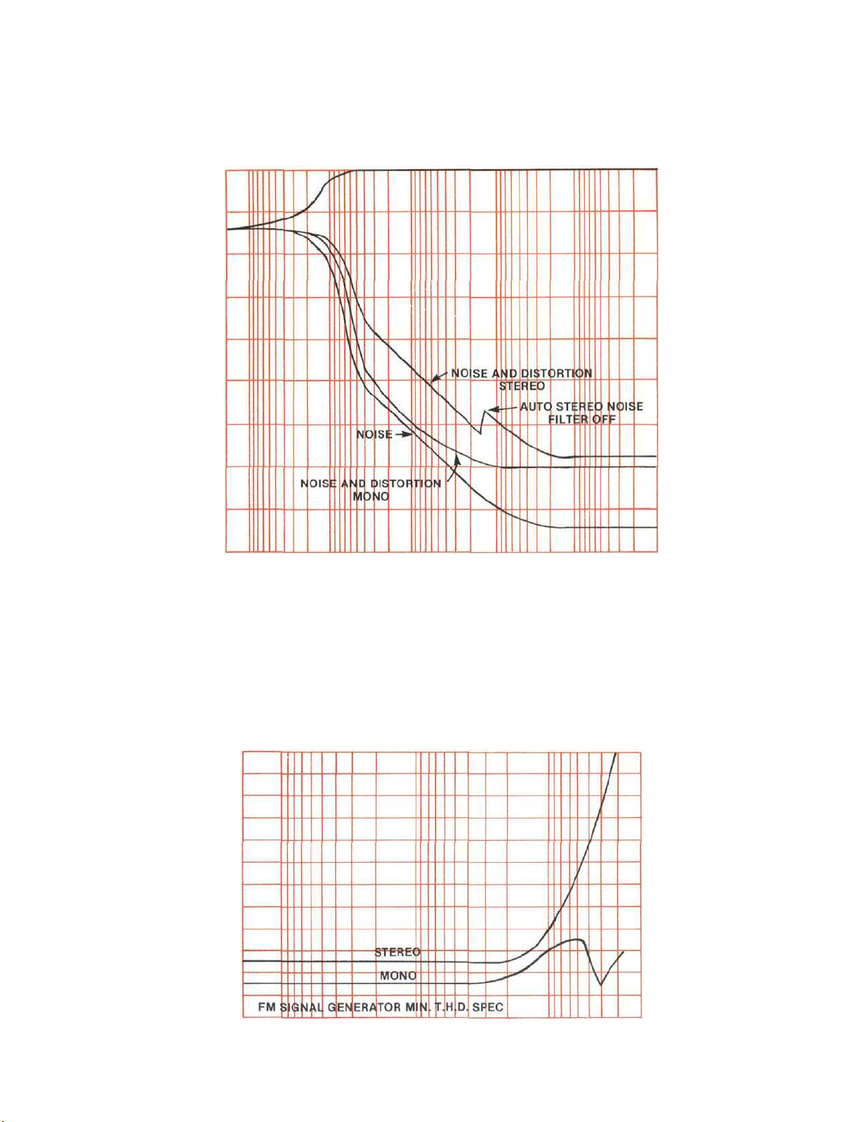
Performance Charts
MR 500 FM SIGNAL PERFORMANCE
98
MHz,
1 kHz MOD
dB
-10
-20
-30
-40
-50
-60
-70
100%
-80
-90
MR 500 T.H.D. @ 100% MODULATION
.14
.13
.12
.11
.10
.09
.08
.07
.06
.05
.04
.03
.02
20 100 1000 10000 20000
FREQUENCY IN CYCLES PER SECOND
100
1000
MICROVOLTS
98 MHz
1k 10k
12
Page 13
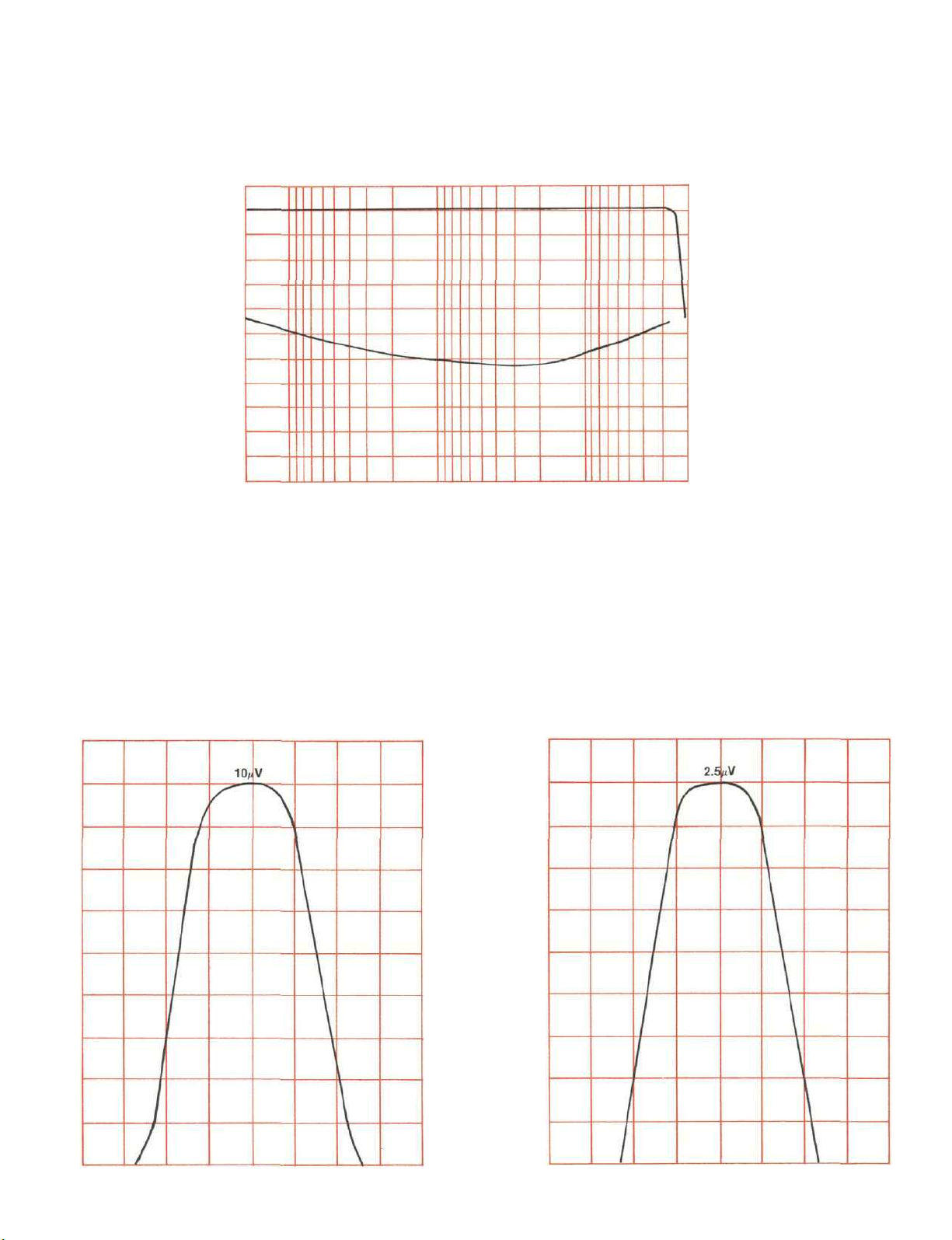
Performance Charts
MR 500 FM FREQUENCY RESPONSE
+ 10
0
-10
-20
-30
-40
-50
-60
-70
-80
-90
-100
20 100 1000 10000 20000
FREQUENCY IN CYCLE PER SECOND
AND SEPARATION
MR 500 SELECTIVITY
DEV IN kHz
-600 -400 -200 0 +200 +400 +600
MR 500 SELECTIVITY
-600 -400 -200 0 +200 +400 +600
0
-10
-20
-30
-40
-50
-60
-70
-80
13
-90
Page 14
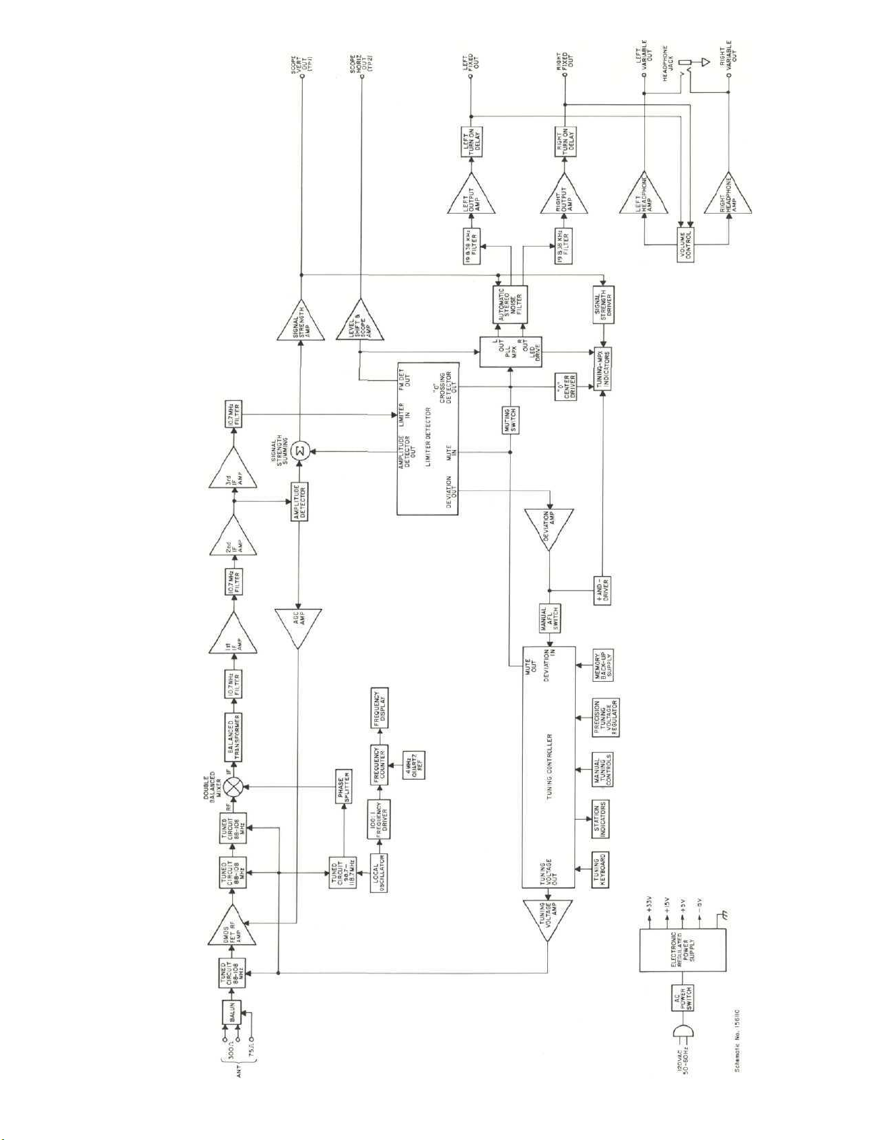
Diagram
Block
14
Page 15

FM Station Log
STATION
DIAL
FREQ.
LOCATION
CITY, STATE
ANTENNA
DIRECTION
REMARKS
TIME— DATE
15
Page 16

VARIOUS REGULATORY AGENCIES
REQUIRE THAT WE BRING THE
FOLLOWING INFORMATION TO
YOUR ATTENTION. PLEASE READ IT
CAREFULLY.
WARNING: TO PREVENT FIRE OR SHOCK
HAZARD, DO NOT EXPOSE THIS UNIT TO
RAIN OR MOISTURE.
The Mclntosh you have purchased is a Model MR
500. It has a serial number located on the rear panel of
the chassis. Record that serial number here:
Serial Number
The model, serial number and purchase date are
important to you for any future service. Record the
purchase date here:
Purchase Date
Upon application, Mclntosh Laboratory provides a
Three-Year Service Contract. Your Mclntosh authorized Service Agency can expedite repairs when you
provide the Service Contract with the instrument for
repair. To assist, record your Service Contract number
here:
Service Contract Number
16
Page 17

Page 18

MclNTOSH LABORATORY INC.
2 CHAMBERS ST., BINGHAMTON, N.Y. 13903-9990
607-723-3512
The continuous improvement of its products is the policy of
Mclntosh Laboratory Incorporated who reserve the right to
improve design without notice.
Printed in U.S.A.
BE022003
 Loading...