

McIntosh MX-114 Owners manual

PREAMPLIFIER
FM TUNER
PRICE $1.25
MX
114
STEREO

The Mclntosh "will to perfection" requires that we probe
constantly into the unknown to bring the performance of our
electronic equipment closer to perfection than ever before.
This requires a constant and relentless search for low noise,
broad band conservative design with an ever lower distortion
factor. This is not required of ordinary equipment of average
designs. It is, for us, a costly but worthwhile scientific and
engineering effort. Our continuing research benefits our customers with the almost complete lack of obsolescence and
the most reliable equipment ever made. It also means the
lowest long-range cost to you. Nearly all of the Mclntosh
equipment ever made is still useable, or in use, though it
may have been made twenty years ago.
CONTENTS
GENERAL DESCRIPTION 2
TECHNICAL DESCRIPTION 3-5
BLOCK DIAGRAM 6
SPECIFICATIONS 7
IN A HURRY 8
CABINET INSTALLATION 9
CONNECTIONS 10-11
FRONT PANEL CONTROLS 12-13
BALANCING 14
USING YOUR STEREO 15
GUARANTEE 16
Your purchase of a Mclntosh instrument
shows that you are a careful discriminat-
ing buyer. One who is interested in quality
performance, quality engineering, quality
manufacturing, and long trouble-free
equipment life. You can protect your in-
vestment by spending a few minutes read-
ing this owner's manual.
When you bought a Mclntosh, you bought
countless hours of musical pleasure and
superior performance. Enjoy it!
MX
PREAMPLIFIER
114
FM TUNER
STEREO
1
I
I
Other values added to this tuner are:
careful control of circuit constants during testing, very high sensitivity and excellent spurious response rejection.
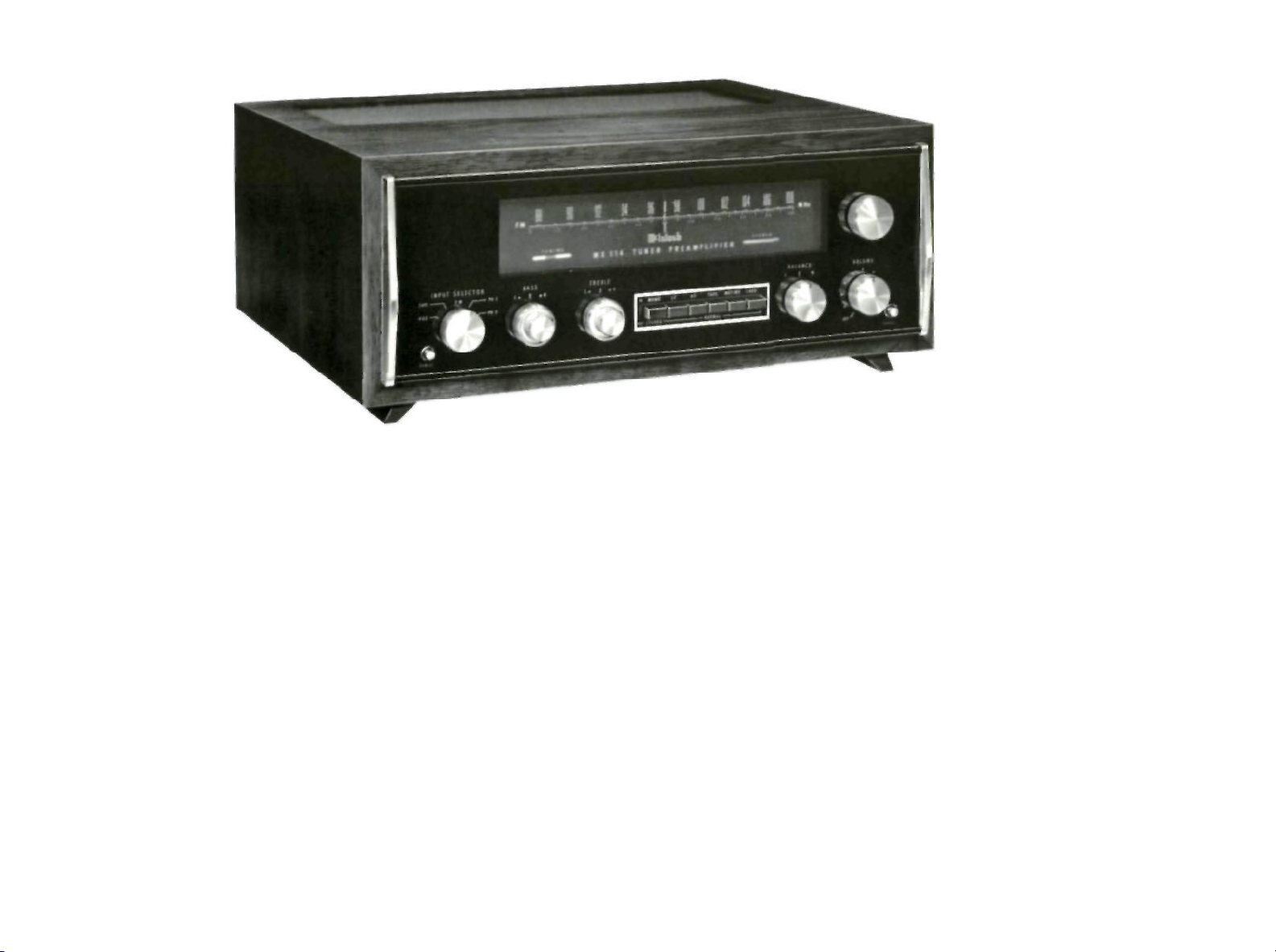
GENERAL DESCRIPTION
The MX 114 combines in one unit an extremely low-distortion preamplifier with a
highly sensitive FM multiplex tuner. The
INPUT SELECTOR gives you a choice of
five different program sources.
The Mclntosh MX 114 is a beautifully
engineered tuner/control center for the
finest stereo sound systems.
The MX 114 is completely solid state, with
the exception of the tuning indicator. The
solid state devices used in the MX 114
are products of the latest technology of
solid state physics.
The extreme care in manufacturing, in
layout design and in quality control prom-
ises the usual Mclntosh extra values of
reliability, performance, and long life.
2
Every desirable feature of a tuner and
preamplifier is included in this design.
FM interstation noise suppression (muting), tuning indicator, FM multiplex indicator, individual channel bass and treble
controls and electronic phase switch
have all been engineered into the MX 114.
The Mclntosh designed PANLOC system
is the first professional installation technique to be used on stereo instruments.
The PANLOC system gives you ease of
installation, operation and maintenance.
By releasing the PANLOC buttons on the
front panel, you can slide the MX 114 out
of its mounting until the second latch engages. The top mounted controls for
interstation noise suppression (muting),
phase switching and front panel lighting
are now available.

TECHNICAL DESCRIPTION
FM SECTION:
The FM consists of two separate modu-
lar sections:
A THE RF SECTION:
This section houses the complete FM
front-end.
The FM circuit employs three junction field effect transistors, two of
which form the very high frequency
amplifier in a series-fed "cascode"
type circuit, giving maximum gain at
minimum thermal noise.
This VHF amplifier is preceded by a
double-tuned circuit and is followed
by a mixer circuit employing the third
junction field effect transistor and a
single-tuned circuit.
The FM local oscillator is designed
for minimum response to temperature variations, making automatic frequency control unnecessary. The
drift rate is less than 10 parts per
megahertz per degree centigrade.
The RF circuits of the MX 114 are
completely shielded and exceed the
FCC requirements for suppression of
oscillator radiation.
Either a 300 ohm or 75 ohm antenna
may be used with the MX 114.
A VHF television antenna which is
suitable for FM reception can be con-
nected to the MX 114. For maximum
performance we recommend a good
FM yagi or log-periodic antenna with
rotator.
B THE FM-IF AND DETECTOR
SECTION:
This section employs two integrated
circuit devices, each capable of amplifying the intermediate frequency
signal from the mixer by a thousand
times (60 db). Lumped selectivity in
the form of two sets of quadrupletuned bandpass filters insure good
intermediate frequency skirt selectivity.
The tuned circuits that make up the
bandpass filters are designed 1or
electrical stability and for electrical
and mechanical resistance to shock
and vibration.
"Hard" limiting is accomplished by
the use of the two integrated circuits.
The limiting is complete at very low
levels of input signals.
A phase or Foster-Seeley discriminator is used as the FM detector, and
is designed for extremely low harmonic distortion in the recovered
output signal. With the "Hard" limiting properties of the preceding two
stages a low capture ratio is obtained.
FM STEREO MULTIPLEX SECTION:
The multiplex section uses a special Mc-
lntosh developed detecting circuit. A particular advantage of this circuit is the
elimination of the critical adjustments
necessary with commonly used matrixing circuits. This circuit detects the L —R
sidebands and automatically matrixes
the recovered information with the L + R
main carrier signal to yield the left and
right program output with maximum separation.
The 19KC pilot signal is filtered from the
composite stereo input signal, amplified
by a special limiting amplifier, doubled
to the 38KC carrier frequency, and then
amplified again by a limiting amplifier.
The composite signal minus the 19KC
pilot is combined with the 38KC carrier
signal and fed to the special detector circuit mentioned above. Balanced full wave
detectors are used to cancel the 38KC
components in the output.
A three section phase linear sharp cut off
filter rejects SCA interference without de-
stroying stereo separation.
FM muting, automatic FM stereo switch-
ing, and an FM stereo indicator are also
part of the multiplex section. The FM
muting operates by detecting ultra-sonic
noise which is present when tuning between stations or when receiving a weak
station. The FM muting operates equally
well, of course, when receiving mono or
stereo stations. The automatic FM stereo
switching activates the stereo multiplex
circuits when receiving FM stereo. On
mono FM stations this circuit is inactive
and therefore maximum signal to noise
ratio is assured at all times.
The FM stereo indicator is lit when the
tuning dial pointer crosses a station
broadcasting FM stereo. The light does
not indicate when tuning between the
stations.
3

TUNING MECHANISM and DIAL DRIVE:
In the MX 114, a new type of mechanical
tuning assembly gives smooth flywheel
tuning.
By controlling the relationship of mass
and mechanical resistance, and by divid-
ing the workloads in the dial drive system,
it becomes nearly impossible to detect
any backlash. Yet, the entire dial drive is
a model of mechanical stability.
For increased tuning accuracy, a section
of the dial pointer is illuminated.
PHONO PREAMPLIFIER
There are three transistors in each channel of the phono preamplifier. The output
of the third transistor is connected by
a negative feedback loop to the emitter
of the input transistor. The feedback loop
reduces noise and distortion. It also provides precision RIAA frequency compensation required for magnetic phonograph
cartridges. Feedback remains in effect
even at 20 Hz, where gain is highest. The
negative feedback also provides a low
output impedance for the tape output.
Phono input overload is virtually impossible. For example, at 1000 Hz, the phono
input can accept 150 millivolts of signal
without overload. Ten millivolts of signal
at the phono input at 1000 Hz will produce 1.2 volts at the tape output. More
than adequate for recording on tape.
4
The selector switch connects either the
output of the phono amplifier, the FM
tuner section or a high level input to the
main preamplifier.
The high level input impedance is 250,000 ohms. The high level input feeds directly to the volume control. A loudness
contour circuit is connected to a tap on
the volume control to provide loudness
compensation. Compensation can be
switched in or out. The high level signal
then feeds to a pair of transistors connected as high gain amplifiers.
In the left channel the second transistor
is connected in a balanced output arrangement allowing the left be in phase
or to be phase reversed. This circuit provides equal amplitude signals so that the
output level does not change when the

used around this pair of transistors to
reduce noise and distortion. The negative feedback provides the low impedance needed to drive the highly selective
filter networks which follow.
The filter networks can be switched in or
out. The high-frequency filter network reduces treble response above 5000 Hz.
The low-frequency filter reduces bass response below 50 Hz. The slope of the
filters is selected for maximum rejection
of commonly encountered noise. Careful
design keeps the loss of usable program
material to a minimum.
The output from the filter circuits is fed
into the balance control. The output of
the balance control drives the first stage
of the tone control section. The remaining two transistors are connected as a
high-gain amplifier stage. The high-gain
of this stage is used to advantage for the
tone control negative feedback circuits.
Negative feedback in the tone control
circuits assures low distortion and accu-
rate shape on the tone-control response
curves. Negative feedback is maintained
at all frequencies, even with the tone controls turned to full boost. Overall distortion is low at all frequencies including
frequencies where maximum boost occurs. The negative feedback also provides the low impedance output required
for the main preamplifier outputs.
CENTER CHANNEL AMPLIFIER
The L + R amplifier consists of a single
transistor connected as a voltage am-
plifier. Negative feedback is used
around the voltage amplifier to maintain low distortion and provide a low
impedance for the center channel
output.
POWER SUPPLY:
The power supply of the MX 114 has
received very special design atten-
tion.
Two separate rectifier circuits are
used. First, a full-wave rectifier supplies D.C. to all audio circuits. The
second full-wave rectifier supplies
D.C. to all tuner and multiplex-decoder circuits.
Both power supplies are very elabor-
ate in design. Specially selected transistors and their associated circuits
have been designed to form two voltage regulators. The regulators use
electronic filtering to insure the lowest possible background hum level,
maximum stability, and extremely
good regulation.
MX
114
5 5
 Loading...