

Page 1
OWNERS
MANUAL
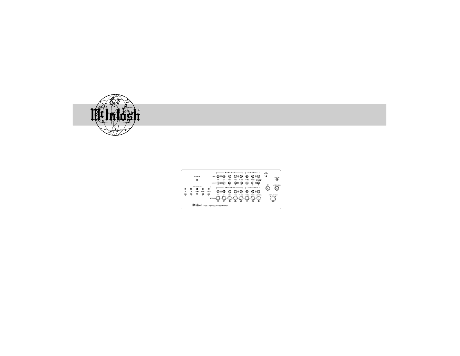
Audio/Video Source Selector
MVS-3
McIntosh Laboratory, Inc. 2 Chambers Street Binghamton, New York 13903-2699 Phone: 607-723-3512 FAX: 607-724-0549
Page 2

Thank You, Please Take A Moment
Thank You
For your decision to own this McIntosh MVS-3 Audio/
Video Source Selector ranks you at the very top among discriminating music listeners. You now have The Best. The
McIntosh dedication to Quality, is assurance that you will
receive many years of enjoyment from this unit.
Please take a short time to read the information in this
manual. We want you to be as familiar as possible with all
the features and functions of your new McIntosh MVS3.
This will ensure that you receive all the performance benefits this equipment can offer you, and that it will become a
highly valued part of your Home Entertainment System.
2
Please Take A Moment
The serial number, purchase date and McIntosh dealer name
are important to you for possible insurance claim or future
service. The serial number is located on the rear panel of the
equipment. The spaces below have been provided for you to
record that information:
Serial Number:
Page 3

Please Take A Moment cont,
Customer Service
Purchase Date:
Dealer Name:
Customer Service
If at any time you have questions about your MVS3 Audio/
Video Source Selector, please contact:
McIntosh Laboratory, Inc.
2 Chambers Street
Binghamton, New York 13903
Phone: 607-723-3512
FAX: 607-724-0549
Copyright 1997 © by McIntosh Laboratory, Inc.
3
Page 4

Table of Contents
Table of Contents
Thank You and Please Take a Moment .............................. 2
Customer Service ............................................................... 3
Table of Contents ............................................................... 4
Safety Instructions ............................................................. 5
Introduction, Performance Features and Installation ....... 10
How to Connect with a Surround Decoder ...................... 11
Front Panel Connections, Control, Display and Switch ... 14
How to Connect with a Control Center ............................ 15
How to Connect to a TV Antenna Input .......................... 18
How to Reassign Inputs ................................................... 20
How to Operate ................................................................ 21
Specifications and Packing Instruction ............................ 23
4
NOTE: The MVS3 can be operated together with a McIntosh
Control Center or Surround Decoder with a Power
Amplifier. Please refer to the following listing of
instructions as a guide:
For use with a McIntosh Surround Decoder
How to Connect ............................................................... 11
How to Reassign Inputs ................................................... 20
How to Operate ................................................................ 21
For use with a McIntosh Control Center
How to Connect ............................................................... 15
How to Operate ................................................................ 21
Page 5
IMPORTANT SAFETY
Safety Intructions
INSTRUCTIONS!
PLEASE READ THEM BEFORE
OPERATING THIS EQUIPMENT.
WARNING SHOCK HAZARD DO NOT OPEN.
AVIS RISQUE DE CHOC NE PAS OUVRIR.
NO USER-SERVICEABLE
PARTS INSIDE. REFER
SERVICING TO
QUALIFIED PERSONNEL
General:
1. Read all the safety and operating instructions, contained
in this owners manual, before operating this equipment.
2. Retain this owners manual for future reference about
safety and operating instructions.
5
Page 6

Safety Instructions cont
3. Adhere to all warnings and operating instructions.
4. Follow all operating and use instructions.
5. Warning: To reduce risk of fire or electrical shock,
do not expose this equipment to rain or moisture.
This unit is capable of producing high sound
pressure levels. Continued exposure to high sound
pressure levels can cause permanent hearing
impairment or loss. User caution is advised and ear
protection is recommended when playing at high
volumes.
6. Caution: to prevent electrical shock do not use this
(polarized) plug with an extension cord, receptacle
or other outlet unless the blades can be fully inserted
6
to prevent blade exposure.
Attention: pour pevenir les chocs elecriques pas
utiliser cette fiche polarisee avec un prolongateur,
une prise de courant ou un autre sortie de courant,
sauf si les lames peuvent etre inserees afond ans en
laisser aucune partie a decouvert.
7. For added protection for this product during a lightning
storm, or when it is left unattended and unused for long
periods of time, unplug it from the wall outlet and disconnect the antenna or cable system. This will prevent
damage to the product due to lightning or power line
surges.
8. Do not use attachments not recommended in this
Page 7

Safety Instructions cont
owners manual as they may cause hazards.
Installation:
9. Locate the equipment for proper ventilation. For example, the equipment should not be placed on a bed,
sofa, rug, or similar surface that may block ventilation
openings; or, placed in a built-in installation, such as a
bookcase or cabinet, that may impede the flow of air
through the ventilation openings.
10. Locate the equipment away from heat sources such as
radiators, heat registers, stoves, or other appliance (including amplifiers) that produce heat.
11. Mount the equipment in a wall or cabinet only as de-
scribed in this owners manual
12. Do not use this equipment near water; for example,
near a bathtub, washbowl, kitchen sink, laundry tub, in
a wet basement or near a swimming pool, etc.
13. Do not place this product on an unstable cart, stand,
tripod, bracket, or table. The equipment may fall, causing serious injury to a person, and serious damage to
the product.
Connection:
14. Connect this equipment only to the type of AC power
source as marked on the unit.
15. Route AC power cords so that they are not likely to be
7
Page 8

Safety Instructions cont
walked on or pinched by items placed upon or against
them, paying particular attention to cords at plugs, convenience receptacles, and the point where they exit from
the instrument.
16. Do not defeat the inherent design features of the polarized plug. Non-polarized line cord adapters will defeat
the safety provided by the polarized AC plug. If the
plug should fail to fit, contact your electrician to replace your obsolete outlet. Do not defeat the safety purpose of the grounding-type plug.
17. Do not overload wall outlets, extension cords or integral convenience receptacles as this can result in a risk
of fire or electric shock.
8
Care of Equipment:
18. Clean the instrument by dusting with a dry cloth. Unplug this equipment from the wall outlet and clean the
panel with a cloth moistened with a window cleaner. Do
not use liquid cleaners or aerosol cleaners.
19. Do not permit objects of any kind to be pushed and/or
fall into the equipment through enclosure openings.
Never spill liquids into the equipment through enclosure
openings.
20. Unplug the power cord from the AC power outlet when
left unused for a long period of time.
Page 9

Safety Instructions cont
Repair of Equipment:
21. Unplug this equipment from the wall outlet and refer
servicing to a qualified service personnel under the following conditions:
A. The AC power cord or the plug has been damaged,
B. Objects have fallen, or liquid has been spilled into
the equipment,
C. The equipment has been exposed to rain or water,
D. The equipment does not operate normally by follow-
ing the operating instructions contained within this
owners manual. Adjust only those controls that are
covered by the operating instructions, as an im-
proper adjustment of other controls may result in
damage and will often require extensive work by a
qualified technician to restore the product to its normal operation,
E. The equipment has been dropped or damaged in any
way,
F. The equipment exhibits a distinct change in perfor-
mance - this indicates a need for service.
22. Do not attempt to service beyond that described in the
operating instructions. All other service should be referred to qualified service personnel.
23. When replacement parts are required, be sure the service technician has used replacement parts specified by
McIntosh or have the same characteristics as the origi-
9
Page 10

Safety Instructions cont, Introduction,
Performance Features and Installation
nal part. Unauthorized substitutions may result in fire,
electric shock, or other hazards.
24. Upon completion of any service or repairs to this product, ask the service technician to perform safety checks
to determine that the product is in proper operating condition.
Introduction
The McIntosh MVS3 Audio/Video Source Selector provides
you with the capability of selecting up two five different
Audio/Video sources when used together with a McIntosh
Control Center or Surround Decoder. It will also allow you
to reassign the five inputs for specific sources.
10
Performance Features
Selection up to five different Audio/Video Sources
Data Control Connections, Remap Inputs
S-Video, Composite Video and Audio Connections
RF Modulator Output
Installation
The MVS3 can be placed upright on a table or shelf. Cool
operation ensures the longest possible operating life for any
electronic instrument. Do not install the MVS3 directly
above a heat generating component such as a high powered
amplifier.
Page 11

How to Connect with a Surround Decoder
1. Connect the MVS-3 power plug to an AC outlet.
2. Connect the MAC-3 DATA OUT to the MVS-3 DATA
IN using a Data cable.
3. Connect a cable from the MVS-3 LV DATA OUTPUT
to the LV player CONTROL (DATA) jack, from the
MVS-3 LV AUDIO INPUTS to the player LV AUDIO
OUT jacks and a Video cable (either S or Composite)
from the MVS-3 LV VIDEO INPUT to the matching
VIDEO OUT on the LV player.
4. Connect the MVS-3 VCR1 AUDIO/VIDEO INPUTS to
the Audio/Video Outputs of the VCR1.
5. Connect a Video cable from the MVS-3 TV VIDEO IN-
How to Connect with
a Surround Decoder
PUT to the Video Output of a Satellite Receiver.
6. Connect the MVS-3 CONTROL CENTER AUDIO OUTPUTS to the MAC-3 ANALOG INPUT.
7. Connect a Video cable from the MVS-3 MONITOR VIDEO OUTPUTS to the Video Input of
a TV Monitor.
NOTES:
1. A Data cable consists of shielded wire with a 1/8
11
Page 12

inch mini phone plug,
either stereo or mono, on
each end Connections are
to the tip (+) and sleeve
(-) of the plug. (McIntosh
Part No. 170-202).
2. If the source component is
non McIntosh, it can be
controlled by adding a
McIntosh RCT Translator
to the system.
12
How to Connect with a Surround
Decoder cont
McIntosh MAC-3
McIntosh MC7106
Page 13

Monitor
VCR
How to Connect with a Surround
Decoder cont
3. The Video Input and Output
connections must be either all
Composite or all S Video, and
cannot be mixed. The two video
circuits are completely separate.
4. If you wish to use a Satellite receiver
The MVS-3 TV VIDEO INPUT must be
reassigned to SAT for this operating
mode. Refer to HOW TO REASSIGN
MVS-3 INPUTS.
McIntosh MLD7020
13
Page 14

Front Panel Connections, Control,
Display and Switch
AUDIO INPUTS receive
audio signals from A/V
components.
DATA IN receives signals
from an MAC-3 DATA
OUT or Control Center
VIDEO DATA PORT.
DATA OUT LEDs light
to indicate which input
has been selected.
DATA OUTPUTS feed
data to Data inputs of
A/V components.
14
AUDIO OUTPUTS feed
signals to VCR and CONTROL CENTER inputs.
VIDEO INPUTS, Composite or S,
receive video signals from A/V
components.
The TV AUDIO volume control adjusts
the volume level of the mono modulated
audio signal sent to the TV set.
The TV CHAN, 3-4 switch
selects the RF TV channel
signal that will be sent to
the TV set.
The ANTENNA jack accepts signals from an antenna or cable system.
VIDEO OUTPUTS feed
video signals to VCR and
MONITOR inputs.
The TV jack feeds RF
signals to the antenna
input of a TV.
Page 15

How to Connect with a Control Center
How to Connect with a Control Center
1. Connect the MVS-3 power plug to an AC outlet.
2. Connect the C38 VIDEO DATA OUT to the MVS-3
DATA IN using a Data cable.
3. Connect a cable from the MVS-3 LV DATA OUTPUT
to the LV player DATA jack, from the MVS-3 LV AUDIO INPUTS to the player LV AUDIO OUT jacks and
a Video cable (either S or Composite) from the MVS-3
LV VIDEO INPUT to the matching VIDEO OUT on
the LV player.
4. Connect the MVS-3 VCR1 AUDIO/VIDEO INPUTS to
the Audio/Video Outputs of the VCR1.
5. Connect a Video cable from the MVS-3 TV VIDEO INPUT to the Video Output of a Satellite Receiver.
6. Connect the MVS-3 CONTROL CENTER AUDIO
OUTPUTS to the C38 VIDEO INPUT.
7. Connect a Video cable from the MVS-3 MONITOR
VIDEO OUTPUTS to the Video Input of a TV Monitor.
NOTES:
1. A Data cable consists of shielded wire with a 1/8 inch mini
phone plug, either stereo or mono, on each end
Connections are to the tip (+) and sleeve (-) of the plug.
(McIntosh Part No. 170-202).
15
Page 16

2. If the source component is non McIntosh, it can be
controlled by adding a McIntosh RCT Translator to the
system.
3. The Video Input and Output connections must be either all
Composite or all S Video, and cannot be mixed. The
two video circuits are completely separate.
16
How to Connect with a Control Center
cont
Monitor
Page 17

VCR
How to Connect with a Control Center
cont
McIntosh MLD7020
17
Page 18

How to Connect to a TV Antenna Input
How to Connect to a TV Antenna Input
1. Remove the antenna cable from the TV antenna connector.
2. Connect a coaxial cable from the MVS-3, TV jack to
the antenna input of the TV in place of the original antenna.
3. Reconnect the antenna lead that was on the TV to the
MVS-3 antenna jack..
4. Select TV channel 3 or channel 4, depending on which
channel of the TV set is to receive the MVS-3, RF
modulated signal.
5. When the MVS-3 is on and operating, video and mono
18
audio from the selected A/V inputs will be sent to the
TV set from the TV jack.
6. When the MVS-3 power is turned off, RF broadcast signals from the ANTENNA jack will be sent straight
through to the TV from the TV jack.
NOTE:
1. The MVS-3 must have its power cord connected to a
switched AC outlet for this mode of operation since its
power must be turned OFF for the ANTENNA - TV Straight
Through function to occur.
2. The MVS-3 RF modulator sends only mono audio signals to
the TV
Page 19

How to Connect to a TV Antenna Input
cont
TV
19
Page 20

How to Reassign Inputs
How to Reassign Inputs
To enable the MVS-3 to switch Audio/Video Signals for the
SAT input of the MAC-3, one of the MVS-3 Inputs must be
reassigned, by using the HR130 Remote Control. The reassignment changes the MVS-3 so it considers a MAC-3 SAT
selection the same as a TV (Input#1).
1. Aim the Remote Control toward the MAC-3 sensor and
press the following push-buttons within 3 seconds between any two push-button presses.
A. Press 2539.
B. Press E (Enter).
C. Press Input 1.
D. Press SAT.
20
The TV (Input 1) DATA LED will flash once, and turn ON
to indicate that the MVS-3 has accepted the reassignment.
Reassign other inputs by following the above procedure.
NOTE: To cancel the MVS-3 input reassignments and return to
the factory default settings, press the numbers 2539,
enter and then the 0 (Zero) push-button on the
HR130 Remote Control. Factory Default Inputs listed
below:
TV Input No. 1
LV Input No. 2
VCR 1 Input No. 3
VCR 2 Input No. 4
V-AUX Input No. 5 (DVD input on the MAC-3)
Page 21

How to Operate
HR130 Remote Control
Input Selections
Numeric Selection
Enter
How to Operate
How to operate in a Surround System with the MAC-3
Select the desired Input program source with the MAC-3
Input switch or with the HR130 Remote Control. After selecting the desired program source, operate the source component according to its owners manual instructions, and
then refer to the MAC-3 Owners manual for operating details.
How to operate with a Control Center
Select the desired input source with the Listen switch or the
Remote Control. Operate the Control Center and associated
21
Page 22

A/V components as directed by their respective owners
manuals.
How to use a Satellite receiver that has an analog output
The MAC-3 can be reassigned to accept Analog audio signals from a satellite receiver, when the SAT digital input is
selected. Reassignment is performed with the HR130 Remote Control.
1. Manually rotate the MAC-3 INPUT selector to ANALOG.
2. Press the MAC-3 SURROUND push-button to ON.
3. Press and HOLD the SURROUND push-button until
22
the LED above the push-button starts to blink ON and
OFF.
4. Using the HR130 Remote Control, press the SAT pushbutton. You will now hear audio from the satellite receiver being sent to the MAC-3 ANALOG input.
If you wish to temporarily go back to receiving digital PCM
audio from the satellite receiver, MANUALLY rotate the
MAC-3 INPUT selector to SAT.
Page 23

Specifications
Power Requirements
100 Volts, 50/60Hz at 20 watts.
110 Volts, 50/60Hz at 20 watts.
120 Volts, 50/60Hz at 20 watts.
220 Volts, 50/60Hz at 20 watts.
230 Volts, 50/60Hz at 20 watts.
240 Volts, 50/60Hz at 20 watts.
NOTE: Refer to the side of the MVS3 for the correct voltage
Dimensions
12 1/4 inches (31.2 cm) Wide, 4 3/4 inches (12.1 cm) High,
3 3/8 inches (8.6 cm) depth
Specifications and Packing Instructions
Weight
5.5 pounds (2.5 Kg)
Packing Instructions
In the event it is necessary to repack the equipment for shipment, use the original shipping carton and packing material
only if they are in good serviceable condition. If a shipping
carton or packing material are needed, please call or write
Customer Service Department of McIntosh Laboratory and
order the following:
Quantity Part Number Description
1 033719 Shipping carton
1 033085 Bubble Pack
23
Page 24

McIntosh Laboratory, Inc.
2 Chambers Street
Binghamton, NY 13903
McIntosh Part No. 03990001
 Loading...