


MFI2266AES
Maytag MFI2266AES, MFI2067AE Series, MFI2266AE Series, MFI2568AE Series, AFI2237AE Series Service Manual
...
Service
This manual is to be used by qualified appliance
technicians only. Maytag does not assume any
responsibility for property damage or personal
injury for improper service procedures done by
an unqualified person.
Ice and Water
This Base Manual covers general information
Refer to individual Technical Sheet
for information on specific models
This manual includes, but is
not limited to the following:
Amana
AFI2237AE*
AFI2538AE*
AFD25BCZX*
AFD25WBZX*
Bottom Mount
Refrigerators
Maytag
MFI2067AE*
MFI2266AE*
MFI2568AE*
16026312
February 2006
Important Information
Important Notices for Servicers and Consumers
Maytag will not be responsible for personal injury or property damage from improper service procedures. Pride and
workmanship go into every product to provide our customers with quality products. It is possible, however , that
during its lifetime a product may require service. Products should be serviced only by a qualified service technician
who is familiar with the safety procedures required in the repair and who is equipped with the proper tools, parts,
testing instruments and the appropriate service information. IT IS THE TECHNICIANS RESPONSIBILITY TO
REVIEW ALL APPROPRIATE SERVICE INFORMA TION BEFORE BEGINNING REPAIRS.
!
To avoid risk of severe personal injury or death, disconnect power before working/servicing on appliance to avoid
electrical shock.
To locate an authorized servicer, please consult your telephone book or the dealer from whom you purchased this
product. For further assistance, please contact:
Customer Service Support Center
CAIR Center
Web Site Telephone Number
WWW.AMANA.COM ............................................... 1-800-843-0304
WWW.JENNAIR.COM ............................................ 1-800-536-6247
WWW.MAYTAG.COM............................................. 1-800-688-9900
CAIR Center in Canada.......................................... 1-800-688-2002
Amana Canada Product .......................................... 1-866-587-2002
WARNING
Recognize Safety Symbols, Words, and Labels
DANGER
!
DANGER—Immediate hazards which WILL result in severe personal injury or death.
WARNING
!
WARNING—Hazards or unsafe practices which COULD result in severe personal injury or death.
!
CAUTION
CAUTION—Hazards or unsafe practices which COULD result in minor personal injury, product or property
damage.
2 16026312 ©2006 Maytag Services

Table of Contents
Important Information.................................................... 2
Product Design ............................................................. 4
Component T esting ....................................................... 5
Service Procedures ......................................................10
Service Equipment .......................................................10
Drier Replacement .......................................................10
Refrigerant Precautions ................................................11
Line Piercing V alves .....................................................11
Open Lines ..................................................................11
Compressor Operational T est .......................................11
Dehydrating Sealed Refrigeration System ....................12
Leak T esting.................................................................12
T esting Systems Cont aining a
Refrigerant Charge .................................................12
T esting Systems Containing
No Refrigerant Charge............................................12
Restrictions..................................................................13
Symptoms.............................................................13
T esting for Restrictions ..........................................13
Evacuation and Charging..............................................14
Evacuation .............................................................14
Charging ................................................................15
Refrigerant Charge .................................................15
HFC134a Service Information .......................................16
Health, Safety , and Handling..................................16
Comparison of CFC12 and HFC134a Properties.....16
Replacement Service Compressor................................17
Compressor T esting Procedures ............................17
Brazing ........................................................................17
Refrigerant Flow 20, 22, 25 cu. ft.................................1 8
Cabinet Air Flow 20, 22, 25 cu. ft ................................1 9
20, 22, 25 cu. ft Machine Compartment
Air Flow Diagram .........................................................20
Water Dispenser Flow..................................................21
Water Flow Schematic.................................................22
Typical External Sweat Pattern...................................23
Troubleshooting Chart................................................24
System Diagnosis........................................................27
Disassembly Procedures
Door Removal
Fresh Food Doors ..................................................30
Freezer Drawer ......................................................30
Refrigerator Compartment
Upper Light Bulb Cover ..........................................30
Light Bulb Assembly..............................................30
Light Bulb Sockets ................................................30
Light Switches .......................................................30
Fresh Food Thermistor...........................................31
Water Tank ............................................................31
Water Dispenser Facade .......................................31
Low Voltage Board.................................................31
Chute Extension / Yoke Assembly.........................31
Ice Box Compartment
Ice Bin Assembly...................................................31
Icemaker Assembly ...............................................31
Ice Box Fan ...........................................................31
Auger Motor...........................................................31
Solenoid ................................................................32
Damper.................................................................. 32
Ice Box Thermistor................................................. 32
Freezer Compartment
Freezer Thermistor.................................................32
Light Socket ..........................................................32
Light Switch...........................................................32
Freezer Back Panel ...............................................33
Evaporator Fan and Evaporator Motor ...................33
Defrost T erminator (thermostat)..............................33
Defrost Heater .......................................................33
Evaporator Removal ...............................................33
Drawer Assembly...................................................34
Drawer Rails ..........................................................34
Rack and Pinion Gear............................................34
Bottom of Cabinet
Front roller assembly .............................................34
Rear roller assembly............................................34
Machine Compartment
Condenser Fan and Fan motor...............................34
Compressor ...........................................................34
Overload/Relay/Capacitor.......................................35
Condensate Drain Pan ...........................................35
Condensate Drain Tube..........................................35
Condenser Removal ...............................................35
Cabinet Back
High Volt age Board ................................................35
Control Board (Fully Electronic)
Programming Mode ...............................................36
Defrost Operation...................................................36
Forced Defrost Mode .............................................36
Service T est Mode .................................................37
Show Room Mode .................................................40
Appendix A
Owner’s Manual........ ........................................A-1
©2006 Maytag Services 16026312 3
Product Design
!
To avoid risk of electrical shock, personal injury, or death, disconnect electrical power source to unit, unless test
procedures require power to be connected. Discharge capacitor through a resistor before attempting to service.
Ensure all ground wires are connected before certifying unit as repaired and/or operational.
Refrigeration System
Compressor forces high temperature vapor into fan
cooled tube and wire condenser where vapor is cooled
and condensed into high pressure liquid by circulation
of air across condenser coil. (See Refrigerant Flow
Diagram, page 18)
High pressure liquid passes into post-condenser loop
which helps to prevent condensation around freezer
compartment opening and through molecular sieve drier
and into capillary tube. Small inside diameter of
capillary offers resistance, decreasing pressure and
temperature of liquid discharged into evaporator.
Capillary diameter and length is carefully sized for each
system.
Capillary enters evaporator at top front. Combined liquid
and saturated gas flows through front to bottom of coil
and into suction line. Aluminium tube evaporator coil is
located in freezer compartment where circulating
evaporator fan moves air through coil and into fresh food
compartment.
Large surface of evaporator allows heat to be absorbed
from both fresh food and freezer compartments by
airflow over evaporator coil causing some of the liquid to
evaporate. Temperature of evaporator tubing near end of
running cycle may vary from -13°F to -25°F.
Saturated gas is drawn off through suction line where
superheated gas enters compressor. To raise
temperature of gas, suction line is placed in heat
exchange with capillary.
WARNING
Defrost System
Fully Electronic Defrost System
The Control Board adapts the compressor run time
between defrosts to achieve optimum defrost intervals
by monitoring the length of time the defrost heater is
on.
After initial power up, defrost interval is 4 hours
compressor run time. Defrost occurs immediately after
the 4 hours.
Note: Once unit is ready to defrost there is a 4 minute
wait time prior to the beginning of the defrost
cycle.
Temperature Controls
Freezer compartment temperature is regulated by air
sensing thermistor at top front of freezer compartment
which actuates compressor. Control should be set to
maintain freezer temperature between 0°F to -2°F.
Fresh food compartment temperature is regulated by an
air damper control governing amount of refrigerated air
entering fresh food compartment from freezer. Fresh
food compartment temperature should be between 38°F
and 40°F.
Evaporator and Ice Box Fans are multiple speed low
voltage fans that change speeds depending on
conditions changing in refrigerator.
4 16026312 ©2006 Maytag Services
Component Testing
!
WARNING
To avoid risk of electrical shock, personal injury, or death, disconnect electrical power source to unit, unless test
procedures require power to be connected. Discharge capacitor through a resistor before attempting to service.
Ensure all ground wires are connected before certifying unit as repaired and/or operational.
Component Description Test Procedures
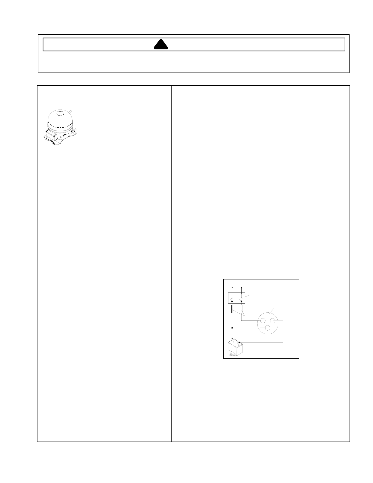
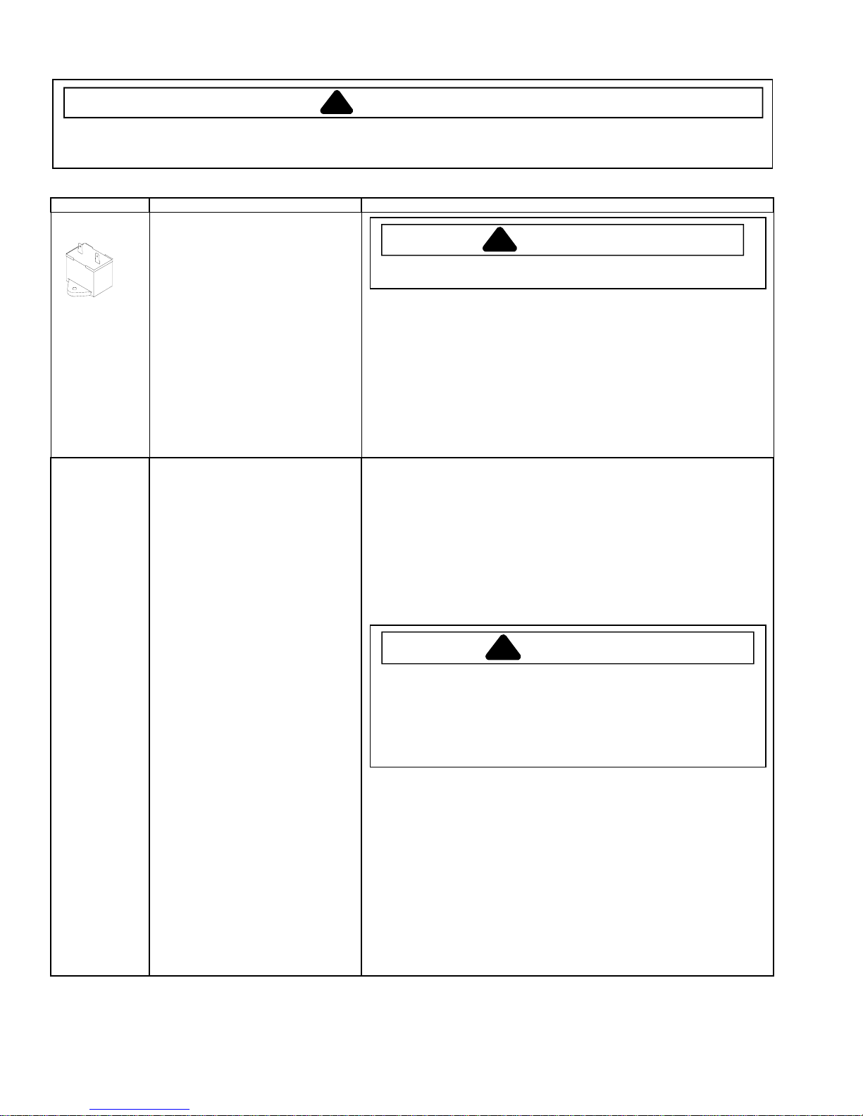
Compressor
When compressor electrical circuit is
energized, the start winding current
causes relay to heat. After an amount of
starting time, the start winding circuit
turns off. The relay will switch off the start
winding circuit even though compressor
has not started (for example, when
attempting to restart after momentary
power interruption).
With “open” relay, compressor will not
start because there is little or no current
to start windings. Overload protection will
open due to high locked rotor run winding
current.
With “shorted” relay or capacitor,
compressor will start and overload
protector will quickly open due to high
current of combined run and start
windings.
With open or weak capacitor, compressor
will start and run as normal but will
consume more energy.
Resistance test
1. Disconnect power to unit.
2. Discharge capacitor by shorting across terminals with a resistor for 1 minute.
NOTE: (Some compressors do not have a run capacitor.)
3. Remove leads from compressor terminals.
4. Set ohmmeter to lowest scale.
5. Check for resistance between
Terminals “S” and “C”, start winding
Terminals “R” and “C”, run winding
If either compressor winding reads open (infinite or very high resistance) or
dead short (0 ohms), replace compressor.
Ground test
1. Disconnect power to refrigerator.
2. Discharge capacitor, if present, by shorting terminals through a resistor.
3. Remove compressor leads and use an ohmmeter set on highest scale.
4. Touch one lead to compressor body (clean point of contact) and other probe
to each compressor terminal.
• If reading is obtained, compressor is grounded and must be replaced.
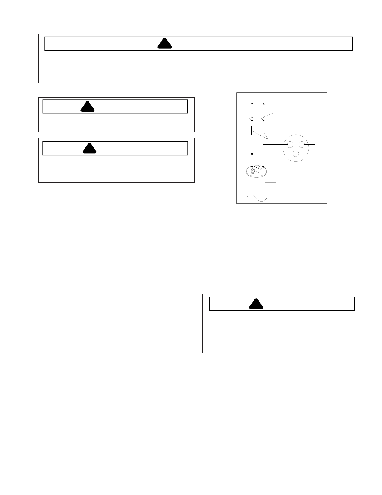
Operation test
If voltage, capacitor, overload, and motor winding tests do not show cause for
failure, perform the following test:
1. Disconnect power to refrigerator.
2. Discharge capacitor by shorting capacitor terminals through a resistor.
3. Remove leads from compressor terminals.
4. Wire a test cord to power switch.
5. Place time delayed fuse with UL rating equal to amp rating of motor in test
cord socket. (Refer to Technical Data Sheet)
6. Remove overload and relay.
7. Connect start, common and run leads of test cord on appropriate terminals of
compressor.
8. Attach capacitor leads of test cord together. If capacitor is used, attach
capacitor lead to a known good capacitor of same capacity.
To AC supply
Switch
Compressor
Fuses
CRS
Capacitor
Test configuration
9. Plug test cord into multimeter to determine start and run wattage and to check
for low voltage, which can also be a source of trouble indications.
10. With power to multimeter, press start cord switch and release.
• If compressor motor starts and draws normal wattage, compressor is okay
and trouble is in capacitor, relay/overload, freezer temperature control, or
elsewhere in system.
• If compressor does not start when direct wired, recover refrigerant at high
side. After refrigerant is recovered, repeat compressor direct wire test. If
compressor runs after recovery but would not run when direct wired before
recover, a restriction in sealed system is indicated.
• If compressor does not run when wired direct after recovery, replace faulty
compressor.
©2006 Maytag Services 16026312 5
Component Testing
!
WARNING
To avoid risk of electrical shock, personal injury, or death, disconnect electrical power source to unit, unless test
procedures require power to be connected. Discharge capacitor through a resistor before attempting to service.
Ensure all ground wires are connected before certifying unit as repaired and/or operational.
Component Description Test Procedures
Capacitor
Condenser Condenser is a tube and wire
Run capacitor connects to relay terminal
3 and L side of line.
Some compressors do not require a run
capacitor; refer to the Technical Data
Sheet for the unit being serviced.
construction located in machine
compartment.
Condenser is on high pressure discharge
side of compressor. Condenser function
is to transfer heat absorbed by refrigerant
to ambient.
Higher pressure gas is routed to
condenser where, as gas temperature is
reduced, gas condenses into a high
pressure liquid state. Heat transfer takes
place because discharged gas is at a
higher temperature than air that is
passing over condenser. It is very
important that adequate air flow over
condenser is maintained.
Condenser is air cooled by condenser fan
motor. If efficiency of heat transfer from
condenser to surrounding air is impaired,
condensing temperature becomes higher.
High liquid temperature means liquid will
not remove as much heat during boiling
in evaporator as under normal conditions.
This would be indicated by higher than
normal head pressures, long run time,
and high wattage. Remove any lint or
other accumulation, that would restrict
normal air movement through condenser.
From condenser the refrigerant flows into
a post condenser loop which helps
control exterior condensation on flange,
center mullion, and around freezer door.
Refrigerant flows through the drier to
evaporator and into compressor through
suction line.
To avoid electrical shock which can cause severe personal injury or death,
discharge capacitor through a resistor before handling.
1. Disconnect power to refrigerator.
2. Remove capacitor cover and disconnect capacitor wires.
3. Discharge capacitor by shorting across terminals with a resistor for 1 minute.
4. Check resistance across capacitor terminals with ohmmeter set on “X1K”
scale.
• Good—needle swings to 0 ohms and slowly moves back to infinity.
• Open—needle does not move. Replace capacitor.
• Shorted—needle moves to zero and stays. Replace capacitor.
• High resistance leak—needle jumps toward 0 and then moves back to
constant high resistance (not infinity).
Leaks in condenser can usually be detected by using an electronic leak detector
or soap solution. Look for signs of compressor oil when checking for leaks. A
certain amount of compressor oil is circulated with refrigerant.
Leaks in post condenser loop are rare because loop is a one-piece copper tube.
For minute leaks
1. Separate condenser from rest of refrigeration system and pressurize
condenser up to a maximum of 235 PSI with a refrigerant and dry nitrogen
combination.
2. Recheck for leaks.
To avoid severe personal injury or death from sudden eruption of high
pressures gases, observe the following:
Protect against a sudden eruption if high pressures are required for leak
checking.
Do not use high pressure compressed gases in refrigeration systems
without a reliable pressure regulator and pressure relief valve in the
lines.
WARNIN G
!
WARNIN G
!
6 16026312
©2006 Maytag Services
Component Testing
!
WARNING
To avoid risk of electrical shock, personal injury, or death, disconnect electrical power source to unit, unless test
procedures require power to be connected. Discharge capacitor through a resistor before attempting to service.
Ensure all ground wires are connected before certifying unit as repaired and/or operational.
Component Description Test Procedures
Overload / Relay
Control board See “Control Board” section for
Evaporator fan
motor
When voltage is connected and relay is
cool, current passes through relay to start
winding.
After a short time, current heats the
resistor in relay and resistance will rise
blocking current flow through relay.
Start winding remains in the circuit through
run capacitor.
Solid state relay plugs directly on
compressor start and run terminals. Relay
terminals 2 and 3 are connected within
relay. Run capacitor is connected to relay
terminal 3. L2 side of 120 VAC power is
connected to relay terminal 2.
troubleshooting information.
Evaporator fan moves air across
evaporator coil and throughout refrigerator
cabinet.
1. Disconnect power to the refrigerator.
2. Remove relay cover and disconnect leads.
3. Check resistance across terminals 2 and 3 with an ohmmeter:
Normal = 3 to 12 ohms
Shorted = 0 ohms
Open = infinite ohms
1. Use Control board testing to check operation of motor.
2. If fan motor does not operate, check for voltage at motor leads.
3. Replace motor if power is present.
4. Replace Control board if no power.
Ice Box fan motor
Right Refrigerator
& Freezer light
switch
Ice maker water
valve
Evaporator heater
(defrost)
Left Refrigerator
Light Switch
Ice Box fan moves air across Ice Maker
and throughout refrigerator cabinet.
Single pole, single throw switch completes
circuit for light when door is open.
Controls water flow to the ice maker.
Controlled by ice maker.
See “Control Board” section for further
testing information.
Activated when defrost thermostat control
board completes circuit through heater.
Single pole, double throw switch
completes circuit for light when door is
open.
1. Use Control board testing to check operation of motor.
2. If fan motor does not operate check for voltage at motor leads.
3. Replace motor if power is present.
4. Replace Control board if no power.
Check resistant across terminals.
Switch arm depressed
“C“ and ”NC” terminals Open
Switch arm up
“C“ and ”NC” terminals Closed
Check resistance across coil windings.
Check resistance across heater.
To check defrost system :
1. Use Control Board testing to check operation of defrost heater.
2. If heater does not operate, check defrost thermostat to see if closed.
3. If no power to heater, replace control board.
Check resistant across terminals.
Switch arm depressed
“C” and “NC” terminals Open
“C” and ”NO” terminals Closed
Switch arm up
“C” and “NC” terminals Closed
“C” and “NO” terminals Open
©2006 Maytag Services 16026312 7
Component Testing
!
WARNING
To avoid risk of electrical shock, personal injury, or death, disconnect electrical power source to unit, unless test
procedures require power to be connected. Discharge capacitor through a resistor before attempting to service.
Ensure all ground wires are connected before certifying unit as repaired and/or operational.
Component Description Test Procedures
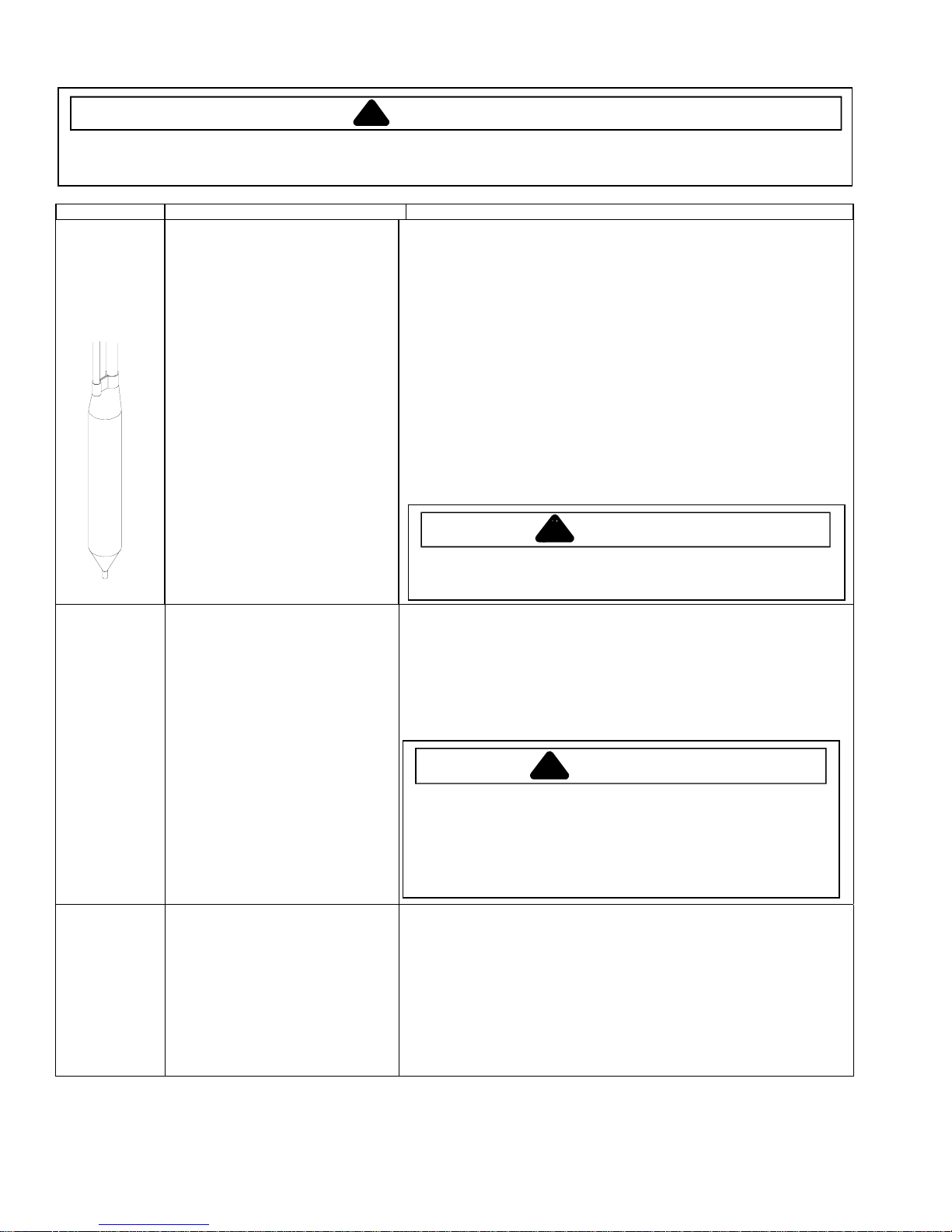
Drier
Evaporator Inner volume of evaporator allows liquid
Thermostat
(defrost)
Drier is placed at post condenser loop
outlet and passes liquified refrigerant to
capillary.
Desiccant (20) 8 x 12 4AXH - 7 M>S> Grams
refrigerant discharged from capillary to
expand into refrigerant gas.
Expansion cools evaporator tube and fin
temperature to approximately -20°F
transferring heat from freezer section to
refrigerant.
Passing through suction line to
compressor, the refrigerant picks up
superheat (a relationship between
pressure and temperature that assures
complete vaporization of liquid
refrigerant) as the result of capillary tube
soldered to suction line.
Refrigerant gas is pulled through suction
line by compressor, completing
refrigeration cycle.
Thermostat is in a series circuit with
terminal main control board and defrost
heater.
Controls the circuit from main control
board through defrost thermostat to
defrost heater. Opens and breaks circuit
when thermostat senses preset high
temperature.
Drier must be changed every time the system is opened for testing or
compressor replacement.
NOTE: Drier used in R12 sealed system is not interchangeable with
drier used in R134a sealed system. Always replace drier in R134a
system with Amana part number B2150504.
Before opening refrigeration system, recover HFC134a refrigerant for safe
disposal.
1. Cut drier out of system using the following procedure. Do not unbraze drier.
2. Applying heat to remove drier will drive moisture into the system.
3. Score capillary tube close to drier and break.
4. Reform inlet tube to drier allowing enough space for large tube cutter.
5. Cut circumference of drier 1 ¼" below condenser inlet tube joint to drier.
6. Remove drier.
7. Apply heat trap paste on post condenser tubes to protect grommets from high
heat.
8. Unbraze remaining part of drier. Remove drier from system.
9. Discard drier in safe place. Do not leave drier with customer. If refrigerator is
under warranty, old drier must accompany warranty claim.
To avoid death or severe personal injury, cut drier at correct location.
Cutting drier at incorrect location will allow desiccant beads to scatter. If
spilled, completely clean area of beads.
Test for leaks in evaporator with electronic leak detector or with soap solution.
Compressor oil is circulated with refrigerant; check for oil when checking for
leaks.
For minute leaks
1. Separate evaporator from rest of refrigeration system and pressurize
evaporator up to a maximum of 140 PSI with a refrigerant and dry nitrogen
combination.
2. Recheck for leaks.
!
To avoid severe personal injury or death from sudden eruption of high
pressures gases, observe the following:
Protect against a sudden eruption if high pressures are required for leak
checking.
Do not use high pressure compressed gases in refrigeration systems
without a reliable pressure regulator and pressure relief valve in the
lines.
Test continuity across terminals.
With power off and evaporator coil below freezing, thermostat should show “0”
ohms when checked with ohmmeter. See “Heater, evaporator (defrost)” section
for additional tests. If evaporator coil is warm, should show 56k ohms with an ohm
meter.
After defrost thermostat opens, thermostat remains open until end of defrost cycle
and refrigerator starts cooling again. Defrost thermostat senses a preset low
temperature and resets (closes).
WARNING
!
WARNIN G
8 16026312
©2006 Maytag Services
Component Testing
!
WARNING
To avoid risk of electrical shock, personal injury, or death, disconnect electrical power source to unit, unless test
procedures require power to be connected. Discharge capacitor through a resistor before attempting to service.
Ensure all ground wires are connected before certifying unit as repaired and/or operational.
Component Description Test Procedures
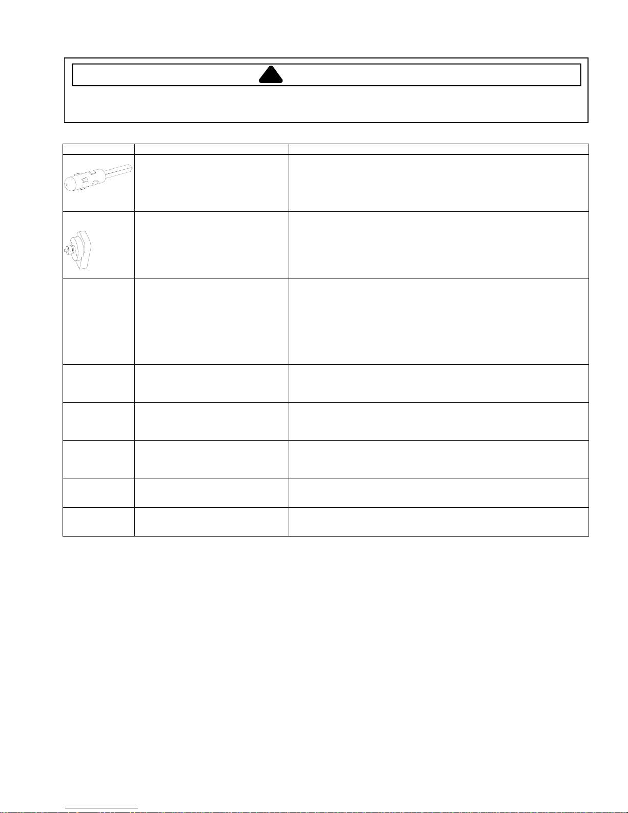
Thermistor
ECM condenser
motor
Electric damper
control
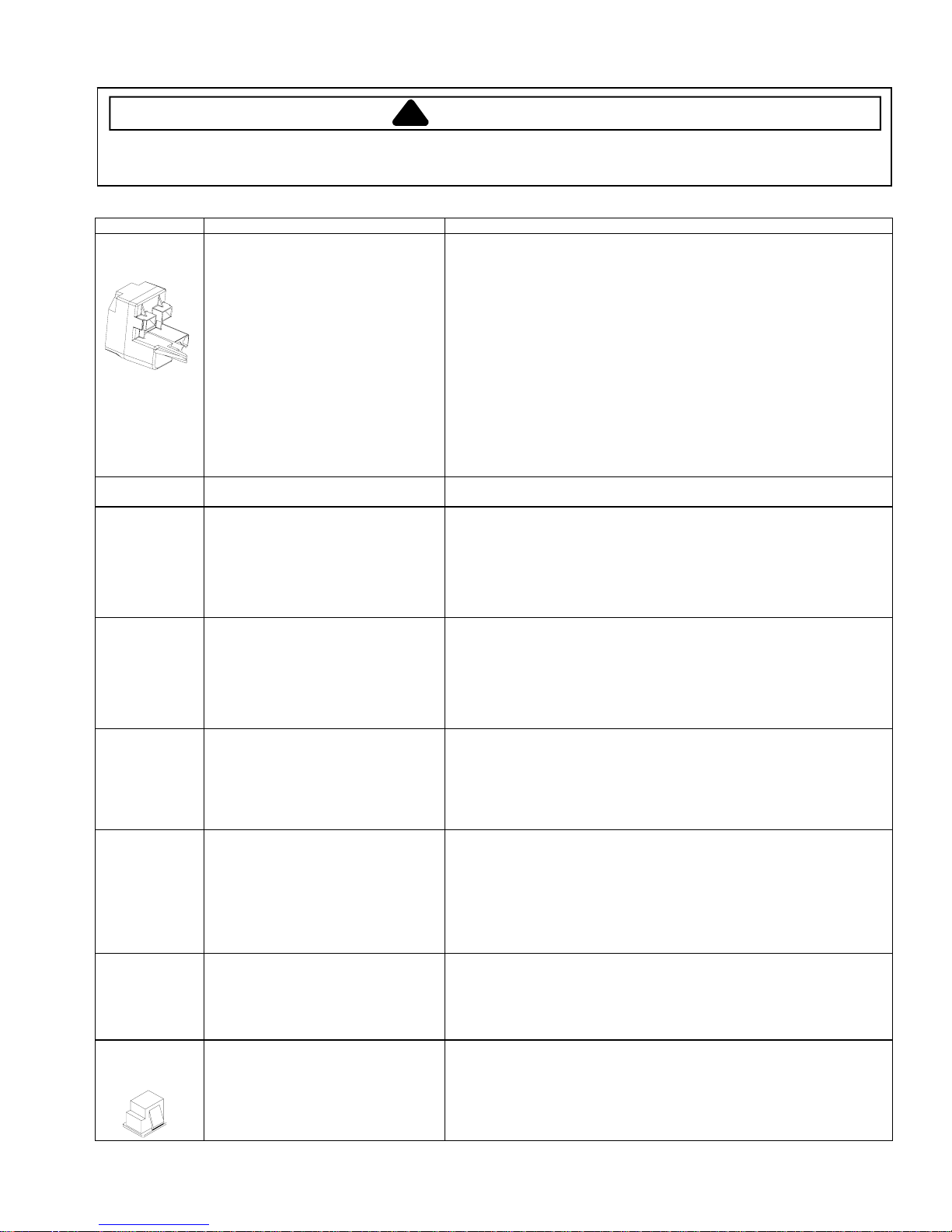
Auger Motor Auger motor is controlled by Dispenser
Ice Box Solenoid Ice Box Solenoid is controlled by
Door Chute Motor Door chute motor is controlled by
DispenserCavity
Heater
Mullion Heater Mullion Heater is controlled by Control
Temperature sensing device Check resistance across leads.
Condenser fan moves cooling air across
condenser coil and compressor body.
Condenser fan motor is in parallel circuit
with compressor.
Damper control balances the air delivery
between refrigerator and freezer
compartments providing temperature
control for refrigerator.
Electrical voltage activates damper
control and door closes restricting flow of
air from freezer/ ice box compartment to
refrigerator compartment.
switch. Depressing dispenser switch
activates Auger Motor, Ice Box Solenoid
and Door Chute Motor.
Dispenser switch. Depressing dispenser
switch activates Auger Motor, Ice Box
Solenoid and Door Chute Motor.
Dispenser switch. Depressing dispenser
switch activates Auger Motor, Ice Box
Solenoid and Door Chute Motor.
Cavity Heater is controlled by Control
Board.
Board.
Nominal
Temperature Resistance
77°F 9,820 - 10182 ohms
36°F 29,198 – 29,788 ohms
0°F 84,561 – 88,011 ohms
1. Use control board testing to check operation of motor.
2. If motor does not operate check for voltage at motor.
3. If no voltage at motor replace control board.
1. Use control board testing to check operation of damper.
2. If damper does not operate check for voltage at damper.
3. If no voltage at damper replace control board.
1. Use control board testing to check operation of motor.
2. If motor does not operate check for voltage at motor.
3. If no voltage at motor replace control board.
1. Use control board testing to check operation of solenoid.
2. If motor does not operate check for voltage at motor.
3. If no voltage at solenoid replace control board.
1. Use control board testing to check operation of motor.
2. If motor does not operate check for voltage at motor.
3. If no voltage at motor replace control board.
1. Use control board testing to check operation of heater.
2. If heater does not operate check for voltage at heater.
3. If no voltage at heater replace Control Board.
1. Use control board testing to check operation of heater.
2. If heater does not operate check for voltage at heater.
3. If no voltage at heater replace Control Board.
©2006 Maytag Services 16026312 9
Service Procedures
!
To avoid risk of electrical shock, personal injury, or death, disconnect electrical power source to unit, unless test
procedures require power to be connected. Discharge capacitor through a 10,000 ohm resistor before attempting
to service. Ensure all ground wires are connected before certifying unit as repaired and/or operational.
Service Equipment
Listed below is equipment needed for proper servicing
of HFC134a systems. Verify equipment is confirmed
by manufacturer as being compatible with HFC134a
and ester oil system.
Equipment must be exclusively used for HFC134a.
Exclusive use of equipment only applies to italic items.
• Evacuation pump
Check with vacuum pump supplier to verify equipment
is compatible for HFC134a. Robinair, Model 15600
2 stage, 6 cubic feet per minute pump is
recommended.
• Four-way manifold gauge set, with low loss hoses
• Leak detector
• Charging cylinder
• Line piercing saddle valve
(Schroeder valves). Seals must be HFC134a and
ester oil compatible. Line piercing valves may be used
for diagnosis but are not suitable for evacuation or
charging, due to minute holes pierced in tubing. Do
not leave mechanical access valves on system.
V alves eventually will leak. Molecules of HFC134a are
smaller than other refrigerants and will leak where
other refrigerants would not.
• Swaging tools
• Flaring tools
• T ubing cutter
• Flux
• Sil-Fos
• Silver solder
• Oil for swaging and flaring
Use only part # R0157532
• Copper tubing
Use only part # R0174075 and # R0174076
• Dry nitrogen
99.5% minimum purity, with -40°F or lower dew point
• Crimp tool
• Tube bender
• Micron vacuum gauge
• Process tube adaptor kit
• Heat trap paste
• ICI appliance grade HFC134a
WARNING
Drier Replacement
Before opening refrigeration system, recover
HFC134a refrigerant for safe disposal.
Every time sealed HFC134a system is repaired, drier
filter must be replaced with, part # B2150504.
Cut drier out of system by completing the following
steps. Do not unbraze drier filter. Applying heat to
remove drier will drive moisture into system.
To avoid risk of severe personal injury or death, cut
drier at correct location. Cutting drier at incorrect
location will allow desiccant beads to scatter.
Completely clean area of beads, if spilled.
1. Score capillary tube close to drier and break.
2. Reform inlet tube to drier allowing enough space
for large tube cutter.
3. Cut circumference of drier at 1-1/4", below
condenser inlet tube joint to drier.
4. Remove drier.
5. Apply heat trap paste on post condenser tubes to
protect grommets from high heat.
6. Unbraze remaining part of drier. Remove drier
from system.
7. Discard drier in safe place. Do not leave drier with
customer. If refrigerator is under warranty, old
drier must accompany warranty claim.
WARNING
!
10 16026312 ©2006 Maytag Services
Service Procedures
!
To avoid risk of electrical shock, personal injury, or death, disconnect electrical power source to unit, unless test
procedures require power to be connected. Discharge capacitor through a 10,000 ohm resistor before attempting
to service. Ensure all ground wires are connected before certifying unit as repaired and/or operational.
Refrigerant Precautions
WARNING
!
To avoid risk of personal injury, do not allow
refrigerant to contact eyes or skin.
CAUTION
!
To avoid risk of property damage, do not use
refrigerant other than that shown on unit serial
number identification plate.
NOTE: All precautionary measures recommended by
refrigerant manufacturers and suppliers apply
and should be observed.
Line Piercing Valves
Line piercing valves can be used for diagnosis, but
are not suitable for evacuating or charging due to
holes pierced in tubing by valves.
NOTE: Do not leave line piercing valves on system.
Connection between valve and tubing is not
hermetically sealed. Leaks will occur.
Open Lines
During any processing of refrigeration system, never
leave lines open to atmosphere. Open lines allow water
vapor to enter system, making proper evacuation more
difficult.
Compressor Operational Test
(short term testing only)
If compressor voltage, capacitor, overload, and motor
winding tests are successful (do not indicate a fault),
perform the following test:
1.Disconnect power to unit.
2.Discharge capacitor by shorting capacitor
terminals through a resistor.
NOTE: Not all units have run capacitor.
3.Remove leads from compressor terminals.
4.Attach test cord to compressor windings.
• Common lead on test cord attaches to C terminal
on compressor.
• Start lead on test cord attaches to S terminal on
compressor.
• Run lead on test cord attaches to R terminal on
compressor.
WARNING
Attaching Capacitor for Compressor Test
5. Connect a known good capacitor into circuit as shown
above. For proper capacitor size and rating, see
technical data sheet for unit under test.
NOTE: Ensure test cord cables and fuses meet
specifications for unit under test (see Technical
Sheet for unit under test).
6. Replace compressor protector cover securely .
7. Plug test cord into outlet, then press and release start
cord switch.
To avoid risk of damage to compressor windings,
immediately disconnect (unplug) test cord from power
source if compressor does not start. Damage to
compressor windings occurs if windings remain
energized when compressor is not running.
If compressor runs when direct wired, it is working
properly. Malfunction is elsewhere in system.
If compressor does not start when direct wired, recover
system at high side. After the system is recovered,
repeat compressor direct wire test.
If compressor runs after system is recovered (but
would not operate when wired direct before recovery) a
restriction in sealed system is indicated.
If motor does not run when wired direct after recovery,
replace faulty compressor.
To AC supply
!
Switch
Compressor
Fuses
CRS
Capacitor
CAUTION
©2006 Maytag Services 16026312 11
Service Procedures
!
To avoid risk of electrical shock, personal injury, or death, disconnect electrical power source to unit, unless test
procedures require power to be connected. Discharge capacitor through a 10,000 ohm resistor before attempting
to service. Ensure all ground wires are connected before certifying unit as repaired and/or operational.
Dehydrating Sealed Refrigeration System
Moisture in a refrigerator sealed system exposed to
heat generated by the compressor and motor reacts
chemically with refrigerant and oil in the system and
forms corrosive hydrochloric and hydrofluoric acids.
These acids contribute to breakdown of motor winding
insulation and corrosion of compressor working parts,
causing compressor failure.
In addition, sludge, a residue of the chemical reaction,
coats all surfaces of sealed system, and will eventually
restrict refrigerant flow through capillary tube.
To dehydrate sealed system, evacuate system (see
paragraph Evacuation).
Leak Testing
DANGER
!
To avoid risk of serious injury or death from violent
explosions, NEVER use oxygen or acetylene for
pressure testing or cleaning out of refrigeration
systems. Free oxygen will explode on contact with
oil. Acetylene will explode spontaneously when put
under pressure.
WARNING
Testing Systems Containing No Refrigerant Charge
1. Connect cylinder of nitrogen, through gauge
manifold, to process tube of compressor and liquid
line strainer.
2. Open valves on nitrogen cylinder and gauge manifold.
Allow pressure to build within sealed system.
3. Check for leaks using soap suds.
If a leak is detected in a joint, do not to attempt to repair
by applying additional brazing material. Joint must be
disassembled, cleaned and rebrazed. Capture refrigerant
charge (if system is charged), unbraze joint, clean all
parts, then rebraze.
If leak is detected in tubing, replace tubing. If leak is
detected in either coil, replace faulty coil.
It is important to check sealed system for refrigerant
leaks. Undetected leaks can lead to repeated service
calls and eventually result in system contamination,
restrictions, and premature compressor failure.
Refrigerant leaks are best detected with halide or
electronic leak detectors.
Testing Systems Containing a Refrigerant Charge
1. Stop unit operation (turn refrigerator of f).
2. Holding leak detector exploring tube as close to
system tubing as possible, check all piping, joints,
and fittings.
NOTE: Use soap suds on areas leak detector cannot
reach or reliably test.
12 16026312 ©2006 Maytag Services
Service Procedures
!
To avoid risk of electrical shock, personal injury, or death, disconnect electrical power source to unit, unless test
procedures require power to be connected. Discharge capacitor through a 10,000 ohm resistor before attempting
to service. Ensure all ground wires are connected before certifying unit as repaired and/or operational.
Restrictions
Symptoms
Restrictions in sealed system most often occur at
capillary tube or filter drier, but can exist anywhere on
liquid side of system.
Restrictions reduce refrigerant flow rate and heat
removal rate. Wattage drops because compressor is
not circulating normal amount of refrigerants.
Common causes of total restrictions are moisture,
poorly soldered joints, or solid contaminants. Moisture
freezes at evaporator inlet end of capillary tube. Solid
contaminants collect in filter drier.
If restriction is on low side, suction pressure will be in a
vacuum and head pressure will be near normal.
If restriction is on high side, suction pressure will be in
a vacuum and head pressure will be higher than
normal during pump out cycle.
Refrigeration occurs on low pressure side of partial
restriction. There will be a temperature difference at
the point of restriction. Frost and/or condensation will
be present in most cases at the point of restriction.
Also, system requires longer to equalize.
Slight or partial restriction can give the same
symptoms as refrigerant shortage including lower than
normal back pressure, head pressure, wattage, and
warmer temperatures.
Total restriction on the discharge side of compressor,
when restriction is between compressor and first half
of condenser, results in higher than normal head
pressure and wattage while low side is being pumped
out.
Testing for Restrictions
To determine if a restriction exists:
1. Attach gauge and manifold between suction and
discharge sides of sealed system.
2. Turn unit on and allow pressure on each side to
stabilize. Inspect condenser side of system. T ubing
on condenser should be warm and temperature
should be equal throughout (no sudden drops at any
point along tubing).
• If temperature of condenser tubing is consistent
throughout, go to step 4.
• If temperature of condenser tubing drops suddenly
at any point, tubing is restricted at point of
temperature drop (if restriction is severe, frost may
form at point of restriction and extend down in
direction of refrigerant flow in system). Go to step 5.
WARNING
3. Visually check system for kinks in refrigeration line
which is causing restriction. Correct kink and repeat
step 2.
4. Turn unit off and time how long it t akes high and low
pressure gauges to equalize:
• If pressure equalization takes longer than 10
minutes, a restriction exists in the capillary tube or
drier filter. Go to step 5.
• If pressure equalization takes less than 10 minutes,
system is not restricted. Check for other possible
causes of malfunction.
5. Recover refrigerant in sealed system.
NOTE: Before opening any refrigeration system,
capture refrigerant in system for safe disposal.
6. Remove power from unit.
To avoid risk of personal injury or property damage,
take necessary precautions against high
temperatures required for brazing.
7. Remove and replace restricted device.
8. Evacuate sealed system.
9. Charge system to specification.
NOTE: Do not use captured or recycled refrigerant in
units. Captured or recycled refrigerant voids any
compressor manufacturer's warranty .
NOTE: Charge system with exact amount of refrigerant.
Refer to unit nameplate for correct refrigerant
charge. Inaccurately charged system will cause
future problems.
CAUTION
!
©2006 Maytag Services 16026312 13
Service Procedures
!
WARNING
To avoid risk of electrical shock, personal injury, or death, disconnect electrical power source to unit, unless test
procedures require power to be connected. Discharge capacitor through a 10,000 ohm resistor before attempting
to service. Ensure all ground wires are connected before certifying unit as repaired and/or operational.
Evacuation and Charging
CAUTION
!
To avoid risk of fire, sealed refrigeration system
must be air free. To avoid risk of air contamination,
follow evacuation procedures exactly.
NOTE: Before opening any refrigeration system, EPA
regulations require refrigerant in system to be
captured for safe disposal.
Proper evacuation of sealed refrigeration system is an
important service procedure. Usable life and
operational efficiency greatly depends upon how
completely air, moisture and other non-condensables
are evacuated from sealed system.
Air in sealed system causes high condensing
temperature and pressure, resulting in increased
power requirements and reduced performance.
Moisture in sealed system chemically reacts with
refrigerant and oil to form corrosive hydrofluoric and
hydrochloric acids. These acids attack motor windings
and parts, causing premature breakdown.
Before opening system, evaporator coil must be at
ambient temperature to minimize moisture infiltration
into system.
Evacuation
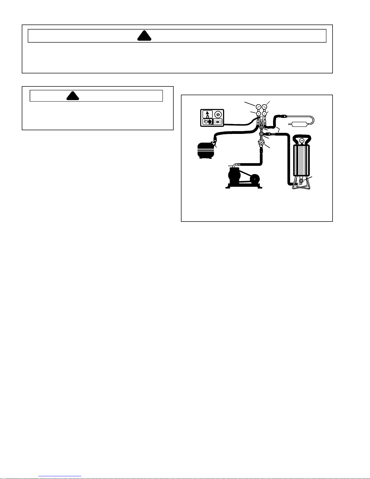
To evacuate sealed refrigeration system:
1. Connect vacuum pump, vacuum tight manifold set
with high vacuum hoses, thermocouple vacuum
gauge and charging cylinder as shown in illustration.
Evacuation should be done through I.D. opening of
tubes not through line piercing valve.
2. Connect low side line to compressor process tube.
3. Connect high side line to drier/process tube.
4. Evacuate both simultaneously. With valve “C” and “F”
closed, open all other valves and start vacuum pump.
Thermistor
Vacuum Gauge
Compressor
Low Side Gauge
Chargi ng Hose
Compressor
Process
Tube
.6 cm Copper
Tubing
Valve
Vacuum Pump
Equipment Setup For Evacuation And Charging
5. After compound gauge (low side) drops to
approximately 29 inches gauge, open valve “C” to
vacuum thermocouple gauge and take micron
reading.
NOTE: A high vacuum pump can only produce a good
vacuum if oil in pump is not contaminated.
6. Continue evacuating system until vacuum gauge
registers 600 microns.
7. At 600 microns, close valve “A” to vacuum pump and
allow micron reading in system to balance. Micron
level will rise.
• If in 2 minutes, micron level stabilizes at 1000
microns or below, system is ready to be charged.
• If micron level rises above 1000 microns and
stabilizes, open valve “A” and continue evacuating.
• If micron reading rises rapidly and does not
stabilize, a leak still exists in system.
Close valve “A” to vacuum pump and valve “C” to
vacuum gauge. Invert charging cylinder and open
charging cylinder valve “F” to add partial charge for
leak checking. With leak detector, check manifold
connections and system for leaks. Af ter locating
leak, capture refrigerant, repair leak, and begin at
step 1.
E
High S ide Gauge
D
Valve
Charging Hose
C
B
A
Drier/Process Tube
Charging
Cylinder
F
Valve
14 16026312 ©2006 Maytag Services
Service Procedures
!
To avoid risk of electrical shock, personal injury, or death, disconnect electrical power source to unit, unless test
procedures require power to be connected. Discharge capacitor through a 10,000 ohm resistor before attempting
to service. Ensure all ground wires are connected before certifying unit as repaired and/or operational.
Charging
NOTE: Do not use captured or recycled refrigerant in
units. Captured or recycled refrigerant voids any
warranty.
NOTE: Charge system with exact amount of refrigerant.
Refer to unit serial plate for correct refrigerant
charge. Inaccurately charged system will cause
future problems.
To charge system:
1. Close valves “A” to vacuum pump and “C” to vacuum
gauge and “E” to low side manifold gauge.
2. Set scale on dial-a-charge cylinder for corresponding
HFC134a pressure reading.
3. Open valve “F” to charging cylinder and let exact
amount of refrigerant flow from cylinder into system.
Close valve.
Low side gauge pressure should rise shortly after
opening charging cylinder valve as system pressure
equalizes through capillary tube.
If pressure does not equalize, a restriction typically
exists at capillary/drier braze joint.
4. If pressure equalizes, open valve “E” to low side
manifold gauge and pinch off high side drier process
tube.
5. Start compressor and draw remaining refrigerant from
charging hoses and manifold into compressor
through compressor process tube.
6. To check high side pinch-off drier process tube. Close
valve “D” to high side gauge. If high side pressure
rises, repeat high side pinch-off and open valve “D”.
Repeat until high side pinch-off does not leak.
7. Pinch-off compressor process tube and remove
charging hose. Braze stub closed while compressor is
operating.
8. Disconnect power. Remove charging hose and braze
high side drier process tube closed.
9. Recheck for refrigerant leaks.
WARNING
Refrigerant Charge
Refrigerant charge in all capillary tube systems is
critical and exact amount is required for proper
performance. Factory charges are shown on serial
plate.
NOTE: Do not use refrigerant other than shown on
serial plate.
©2006 Maytag Services 16026312 15
Service Procedures
!
WARNING
To avoid risk of electrical shock, personal injury, or death, disconnect electrical power source to unit, unless test
procedures require power to be connected. Discharge capacitor through a 10,000 ohm resistor before attempting
to service. Ensure all ground wires are connected before certifying unit as repaired and/or operational.
HFC134a Service Information
CAUTION
HFC134a is alternative refrigerant for CFC12.
HFC134a has an ozone depletion potential (ODP)
factor of 0.0 and a global warming potential (GWP)
factor of 0.27. HFC134a is not flammable and has
acceptable toxicity levels. HFC134a is not
interchangeable with CFC12. There are significant
differences between HFC134a and CFC12 which must
be considered when handling and processing
refrigeration system.
Health, Safety, and Handling
Health, safety and handling considerations for
HFC134A are virtually no different than those for
CFC12.
Health, Safety, and
Handling
Allowable overall
exposure limit
Vapor exposure to skin No effect Same
Liquid exposure to skin Can cause frostbite Same
Vapor exposure to eye Very slight eye irritant Same
Liquid exposure to eye Can cause frostbite Same
Above minimum exposure
limit
Safety and handling Wear appropriate skin
Spill management Remove or extinguish
Fire explosion hazards May decompose if
Disposal procedures Recycle or reclaim. Same
1,000 ppm Same
Can cause Asphyxiation,
Tachycardia, and Cardia
Arrhythmias
and eye protection. Use
with adequate
ventilation.
ignition or combustion
sources. Evacuate or
ventilate area.
contact with flam es and
heating elements.
Container may explode
if heated due to resulting
pressure rise.
Combustion products
are toxic.
CFC12 HFC134a
Same
Same
Same
Same
To minimize contamination, exercise extreme care
when servicing HFC134A sealed systems.
• No trace of other refrigerants is allowed in HFC134a
systems. Chlorinated molecules in other refrigerants
such as CFC12, etc. will lead to capillary tube
plugging.
• Ester oil is used in HFC134a systems. Do not use
mineral oil. HFC134a and mineral oils cannot be
mixed. If mineral oils were used in HFC134a systems,
lubricant would not return to compressor and would
cause early compressor failure. If significant amount of
oil has been lost from compressor, replace oil rather
than adding oil.
• Ester oils used in HFC134a systems are so
hydroscopic that by the time an inadequate system
performance is detected, oil will be saturated with
moisture.
• CFC12 has much higher tolerance to system
processing materials, such as drawing compounds,
rust inhibitors, and cleaning compounds, than
HFC134a. Such materials are not soluble in HFC134a
systems. If materials were to be washed from system
surfaces by ester oils, they could accumulate and
eventually plug capillary tube.
• Care must be taken to minimize moisture entering
HFC134a system. Do not leave compressor or system
open to atmosphere for more than 10 minutes.
Excessive moisture in HFC134a system will react with
compressor oil and generate acid.
• Compressor must be replaced when performing low
side leak repair.
• Drier filter must always be replaced with service drier
filter, part #B2150504.
Important: Unbrazing drier filter from tubing will drive
moisture from desiccant and into system, causing
acids to form. Do not unbraze filter drier from tubing. If
CFC12 service drier was installed in HFC134A system,
drier could overload due to excessive moisture.
• HFC134a compatible copper tubing, part #R0174075
(1/4" O.D. X 18" length) and part #R0174076 (5/16"
O.D. X 24" length) must be used when replacing
tubing.
• Avoid system contamination by using Towerdraw E610
evaporating oil, part # R0157532, when flaring,
swaging, or cutting refrigeration tubing.
!
16 16026312 ©2006 Maytag Services
Service Procedures
!
To avoid risk of electrical shock, personal injury, or death, disconnect electrical power source to unit, unless test
procedures require power to be connected. Discharge capacitor through a 10,000 ohm resistor before attempting
to service. Ensure all ground wires are connected before certifying unit as repaired and/or operational.
Replacement Service Compressor
HFC134a service compressors will be charged with
ester oil and pressurized with dry nitrogen. Before
replacement compressor is installed, pull out 1 rubber
plug. A pop from pressure release should be heard. If
a pop sound is not heard, do not use compressor.
Positive pressure in compressor is vital to keep
moisture out of ester oil. Do not leave compressor
open to atmosphere for more than 10 minutes.
Compressor Testing Procedures
WARNING
!
To avoid death or severe personal injury, never use
oxygen, air or acetylene for pressure testing or
clean out of refrigeration system. Use of oxygen,
air, or acetylene may result in violent explosion.
Oxygen may explode on contact with oil and
acetylene will spontaneously explode when under
pressure.
Refer to Technical Data Sheet “Temperature
Relationship Chart” for operating watts, test points,
and temperature relationship test for unit being tested.
• T emperature testing is accomplished by using 3 lead
thermocouple temperature tester in specific locations.
Test point T-1 is outlet on evaporator coil and T-2 is
inlet. Test point T-3 is suction tube temperature
midway between where armaflex ends and suction
port of compressor (approximately 12 inches from
compressor).
• Thermocouple tips should be attached securely to
specified locations.
• Do not test during initial pull down. Allow one off cycle
or balanced temperature condition to occur before
proceeding with testing.
• Refrigerator must operate minimum of 20 minutes
after thermocouples are installed.
• Turn control to colder to obtain required on time.
• Wattage reading must be recorded in conjunction with
temperature test to confirm proper operation.
• Suction and head pressures are listed on
“Temperature and Relationship Chart”. Normally these
are not required for diagnosis but used for confirmation
on systems which have been opened.
WARNING
Brazing
To avoid risk of personal injury or property damage,
take necessary precautions against high
temperatures required for brazing.
Satisfactory results require cleanliness, experience,
and use of proper materials and equipment.
Connections to be brazed must be properly sized, free
of rough edges, and clean.
Generally accepted brazing materials are:
• Copper to copper joints: SIL-FOS (alloy of 15
percent silver, 80 percent copper, and 5 percent
phosphorous). Use without flux. Recommended
brazing temperature is approximately 1400°F. Do not
use for copper to steel connection.
• Copper to steel joints: SIL VER SOLDER (alloy of 30
percent silver, 38 percent copper, 32 percent zinc).
Use with fluoride based flux. Recommended brazing
temperature is approximately 1200°F.
• Steel to steel joints: SILVER SOLDER (see copper
to steel joints).
• Brass to copper joints: SIL VER SOLDER (see
copper to steel joints).
• Brass to steel joints: SILVER SOLDER (see copper
to steel joints).
CAUTION
!
©2006 Maytag Services 16026312 17
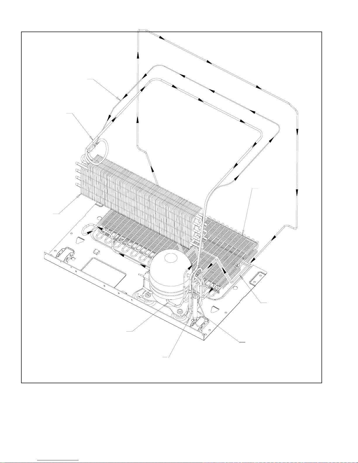
Refrigerant Flow
R
CAPILLARY
TUBE
Not e : Capillary Tub e and
Suction Tube are
located under Fresh
SUCTION
Food floor.
TUBE
CONDENSER
EVAPORATO R
COMPRESSOR
DISCHARGE
TUBE
POST CONDENSE
TUBE
DRYER
PROCESS
TUBE
18 16026312 ©2006 Maytag Services
20, 22, 25 cu. ft. Bottom Mount
Refrigerant Flow Diagram
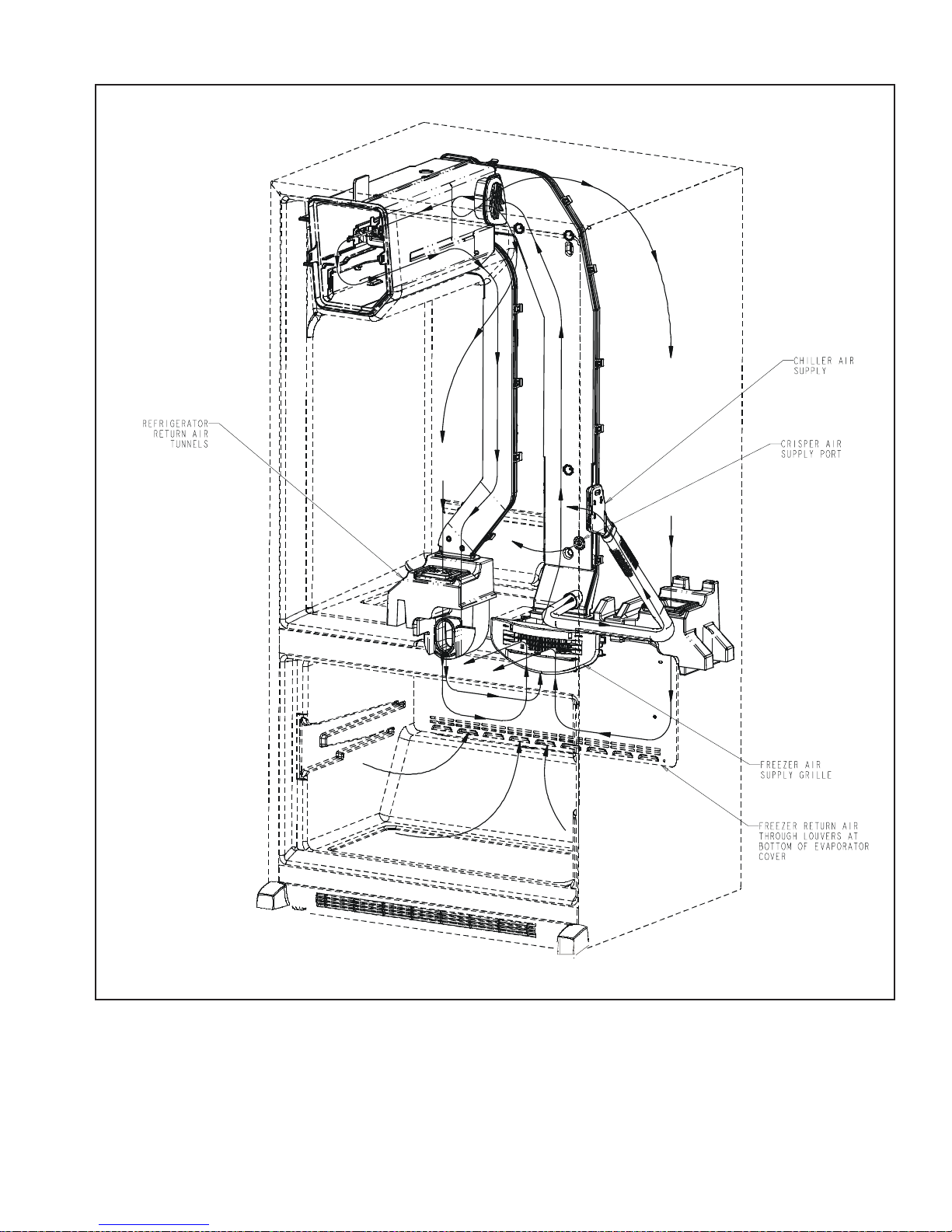
Cabinet Air Flow
©2006 Maytag Services 16026312 19
20, 22, 25 cu. ft. Bottom Mount
Cabinet Air Flow Diagram
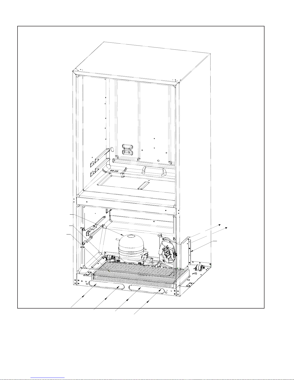
Machine Compartment Air Flow
COMPRESSOR
DRIP PAN
CONDENSER
20, 22, 25 cu. ft. Model Bottom Mount
Machine Compartment Air Flow Diagram
CONDENSER FAN
ASSEMBLY
20 16026312 ©2006 Maytag Services
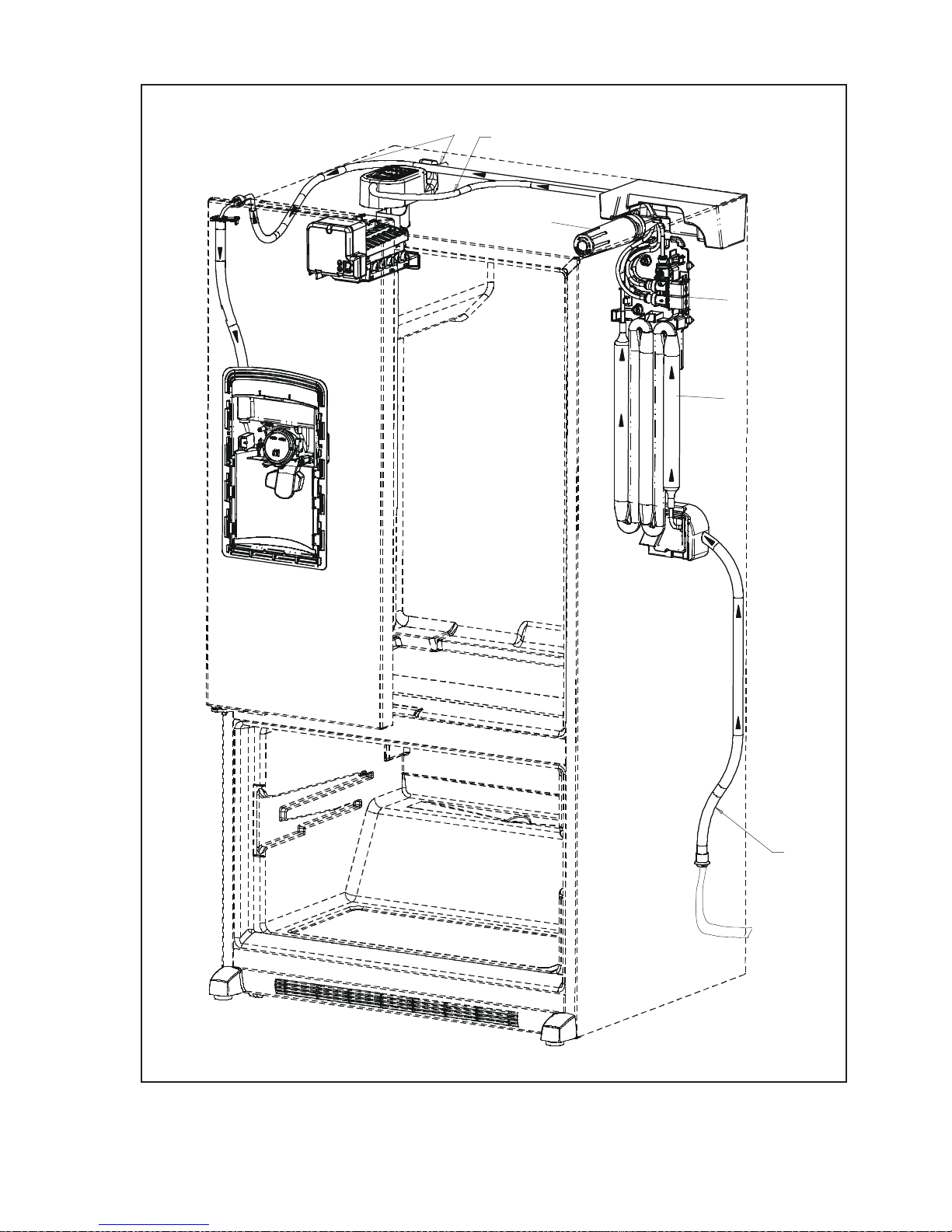
Water Dispenser
Water Inlet
to Dispenser
Water Inlet
to Ice Maker
Water Filter
Water Solenoid
Water Solenoid
to Ice Maker &
to Ice Maker &
Dispenser
Dispenser
Water T ank
to Ice Maker &
Dispenser
©2006 Maytag Services 16026312 21
Water
Line
20, 22, 25 cu. ft. Model Bottom Mount
Water Flow Diagram
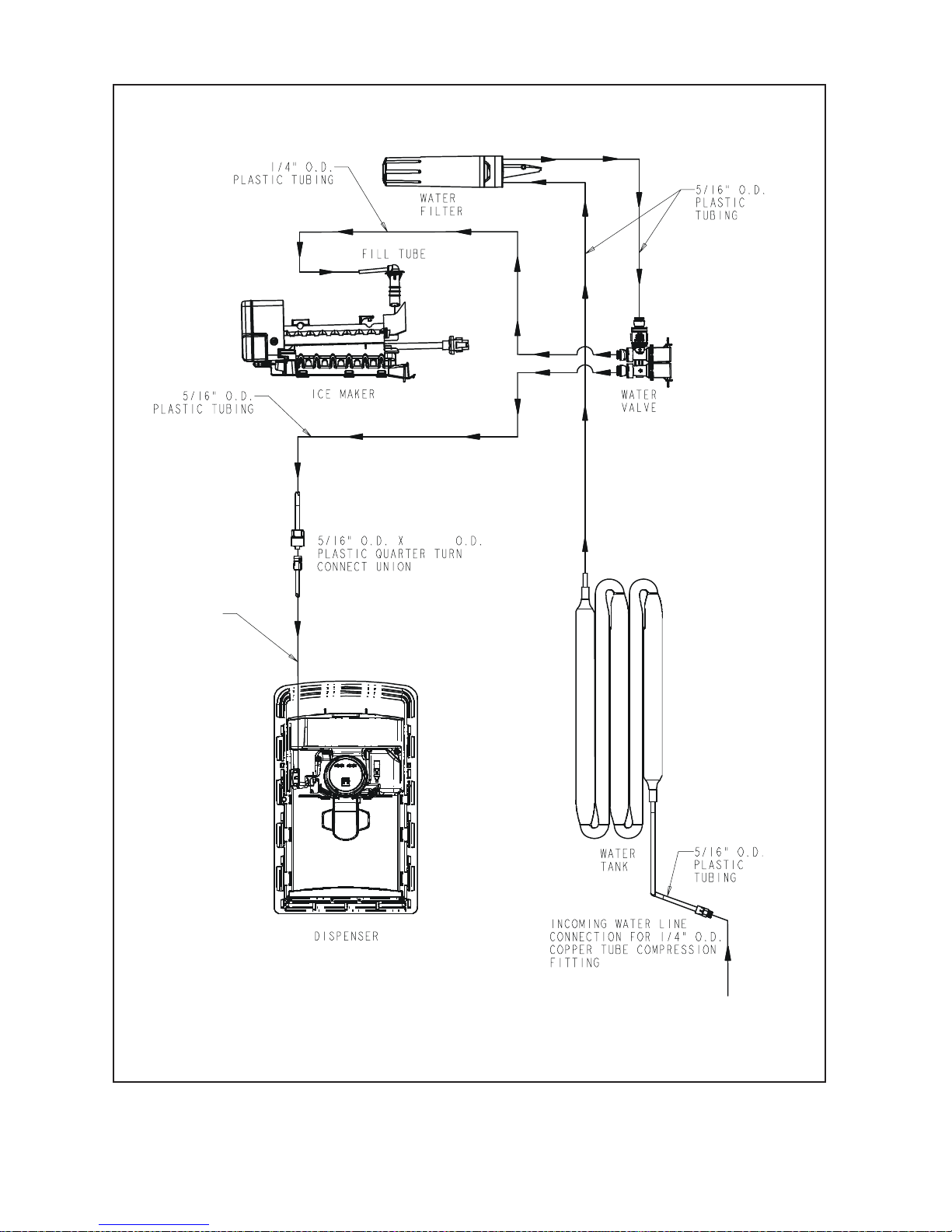
Water Flow Schematic
1/4 “ O.D.
PLASTIC TUBING
1/4 “
22 16026312 ©2006 Maytag Services
20, 22, 25 cu. ft. Model Bottom Mount
Water Flow Schematic
 Loading...