


1. TABLE OF CONTENTS |
|
Publication date: 28 Jun 2007 |
|
1. TABLE OF CONTENTS ................................................................................................ |
1 |
2. IMPORTANT SAFETY INSTRUCTIONS....................................................................... |
2 |
3. TECHNICAL SPECIFICATIONS ................................................................................... |
5 |
4. MACHINE INSTALLATION ........................................................................................... |
9 |
4.1. MACHINE INSPECTION ......................................................................................................................... |
9 |
4.2. WASHER STORAGE............................................................................................................................... |
9 |
4.3. WASHER POSITIONING......................................................................................................................... |
9 |
4.4. SHIPPING BRACKETS ......................................................................................................................... |
12 |
4.5. ELECTRICAL CONNECTION................................................................................................................ |
14 |
4.6. WATER CONNECTION......................................................................................................................... |
17 |
4.7. STEAM CONNECTION ......................................................................................................................... |
19 |
4.8. WATER DRAIN CONNECTION ............................................................................................................ |
19 |
4.9. AIR VENT CONNECTION ..................................................................................................................... |
20 |
4.10. LIQUID SOAP CONNECTION............................................................................................................. |
20 |
4.11. PREPARING THE MACHINE FOR OPERATION............................................................................... |
23 |
5. MAINTENANCE AND ADJUSTMENTS ...................................................................... |
24 |
5.1. MAINTENANCE..................................................................................................................................... |
24 |
5.2. ADJUSTMENTS AND PART´S EXCHANGES..................................................................................... |
25 |
5.2.1. ADJUSTMENT OF DOOR SEAL THRUST .................................................................................... |
25 |
5.2.2. REPLACEMENT OF DOOR RUBBER ........................................................................................... |
26 |
5.2.3. ADJUSTING OF VIBRATION SWITCH .......................................................................................... |
26 |
5.2.4. REPLACEMENT / REGULATION OF THE BELT .......................................................................... |
27 |
5.2.5. WATER FILTERS............................................................................................................................ |
28 |
5.2.6. TIGHTENING MOMENTS............................................................................................................... |
28 |
5.2.7. FUSES ............................................................................................................................................ |
28 |
6. TROUBLESHOOTING AIDS ....................................................................................... |
29 |
6.1. ERROR HANDLING .............................................................................................................................. |
29 |
6.2. PROBLEM CHECK LIST ....................................................................................................................... |
29 |
6.3. DOOR FAILS TO OPEN ........................................................................................................................ |
31 |
7. LIST OF RECOMMENDED SPARE PARTS ............................................................... |
32 |
8. PUTTING THE MACHINE OUT OF SERVICE ............................................................ |
33 |
8.1. DISCONNECTING THE MACHINE....................................................................................................... |
33 |
8.2. MACHINE LIQUIDATION ...................................................................................................................... |
33 |
8.2.1. POSSIBILITY OF THE MACHINE LIQUIDATION BY THE SPECIALIZED COMPANY ........................ |
33 |
8.2.2. POSSIBILITY OF THE MACHINE LIQUIDATION BY OWN POTENTIAL ..................................... |
33 |
100646G MAYTAG PUB DATE 28 JUN 2007.DOC |
INSTALLATION AND MAINTENANCE MANUAL |
1 |

2. IMPORTANT SAFETY INSTRUCTIONS
WARNING - SAVE THESE INSTRUCTIONS FOR LATER USE.
Failure to comply with the instructions may lead to incorrect use of the appliance, and may result in risk of fire, bodily injuries or death and/or damage to the laundry and/or the appliance.
WARNING - Read the IMPORTANT SAFETY INSTRUCTIONS in this manual carefully before operating the appliance. Improper use of the appliance may cause risk of fire, electrical shock or serious body injuries or death as well as serious damage to the appliance.
♦This English version is the original version of this manual. The instructions for the appliance are only complete with the programming, user and spare parts information.
♦Safety instructions included in manuals for personnel operating the appliance must be printed and posted on a visible place near the machine in the laundry room.
♦The washer extractor is designed for fabrics washing only, other objects can damage the washer and can cause damage or injuries.
♦The manufacturer is not responsible for the damage to the fabrics that are washed by an inappropriate washing method.
♦Always follow the instructions and/or warnings that are stated on the fabrics, washing products or cleaning products mentioned by the manufacturer.
♦The washer must be set up in accordance with the instructions. All drain, inlet, electrical connections, ventilation, groundings and other connections must be done in according to the installation manual, in compliance with the local standards done by qualified technicians with proper authorization.
♦The valid standards for connecting to the local power network (TT,TN,IT,…) must be followed.
In the standard execution, the appliance may not be suitable for connecting to an IT supply system. Contact your commercial distributor for assistance.
♦All appliances are produced according the EMC-directive (Electro-Magnetic-Compatibility). They can be used in restricted surroundings only (comply minimally with class A requirements). For safety reasons there must be kept the necessary precaution distances with sensitive electrical or electronic device(s).
♦Do not change the parameters of the frequency inverter. This can cause serious injury, fire, washer damage, etc.
♦During transportation and storage never use excessive forces on the packing because components can be damaged protruding the contour line of the appliance.
♦Use copper conductors only. This appliance must be connected to a supply circuit to which no lighting units or general-purpose receptacles are connected.
♦Any changes concerning the installation which are not described in this Installation Manual must be approved by the supplier or manufacturer. Otherwise, the supplier and manufacturer are not responsible for potential injuries to operators or for any damages. Interventions in the appliance execution or functions are not allowed, and the manufacturer refuses any responsibility in such cases.
♦The washer extractor must be installed on level. If not, the washer may become unbalanced during extraction and, although fitted with an unbalance safety, the washer may become seriously damaged what may result in bodily injuries.
♦Never put the washer in operation when the transporting braces are not removed. The washer should always be tested before use.
♦Keep the appliance top and surface and the area around clean and clear of combustible or flammable products.
♦Do not store flammable materials around the appliances. Define the dangerous areas in the laundry room and obstruct an admission to them during appliances operating.
♦Do not wash articles that have been previously cleaned in, wash in soaked in, or spotted with gasoline, dry-cleaning solvents, or other flammable or explosive substances as they give off vapors that could ignite or explode.
♦Do not add gasoline, dry-cleaning solvents, or other flammable or explosive substances to the wash water. These substances give off vapors that could ignite or explode.
♦Under certain conditions, hydrogen gas may be created in the hot water system that has not been used for two or more weeks. HYDROGEN GAS IS EXPLOSIVE. If the hot water system has not been used for such period open all hot water taps and let the water run out for few minutes. This will release any accumulated gas. As this gas is flammable, do not smoke or use open flames during this time.
♦TEMPERATURE IN WASHING MACHINE TUB: The electronic controller uses the temperature sensor in the tub to control the temperature of the washing bath. There are a lot of things that have influence on the temperature measurement. Therefore the temperature control of the washing bath is not very precise.
2 |
INSTALLATION AND MAINTENANCE MANUAL |
100646G MAYTAG PUB DATE 28 JUN 2007.DOC |
♦Always strictly comply with the instructions that are written on the laundry chemicals-, laundry aids-, dry-cleaning solventsand disinfectants packaging to avoid personal injury. Keep these agents out of the reach of children, preferably in a locked cabinet.
♦ Do not tamper the washer-extractor controls and do not bypass the safety instructions and the warnings.
♦Do not use some means on the soap dispenser lid to hold it open by filling or when the machine operates. The discharge or splashing of hazardous liquid can cause serious scalding and burning.
♦Do not operate the appliance when parts are broken or missing or when covers are open. The appliance may not be operated until the fixed guards are put correctly in place.
♦The appliance must not be stored, installed or exposed to the weather, extreme low or high temperature and humidity levels. Do not hose down the washer. NEVER allow the appliance to get wet.
♦Check the functioning of the door lock mechanism on regular base. NEVER bypass the doorlock mechanism.
♦Disconnect the power and close all water and steam supply before cleaning, servicing and at the end of each operating day.
♦Out of the venting at the back of the washer can escape warm vapor or and hot air. Do not cover the vent but protect it sufficiently. It serves air gap and as a vapor outlet to prevent pressure building in the washer.
♦Do not repair or replace any part of the appliance or attempt any servicing unless specifically recommended in the service manual or published user-repair instructions that you understand and have the skills to carry out. Only qualified service personnel may open the appliance to carry out servicing.
♦Information contained in this manual is intended for use by a qualified service technician familiar with proper and safe procedures to be followed when repairing an electrical appliance. All tests and repairs should be performed by a qualified service technician equipped with proper tools and measuring devices. All component replacements should be made by a qualified service technician using only factory approved replacement parts.
♦Improper assembly or adjustment may occur if service or repair is attempted by persons other then qualified service technicians or if parts other then approved replacement parts are used. Improper assembly or adjustment can create hazardous conditions.
♦There can be a risk of injury or electrical shock while performing services or repairs. Injury or electrical shock can be serious or even fatal. Consequently, extreme caution should be taken while performing voltage checks on individual components or a product. PLEASE NOTE: Except as necessary to perform a particular in servicing a product, the electrical power supply should ALWAYS be disconnected when servicing a product.
♦All industrial (OPL - On Premise Laundry) washers are designed for use in Laundry with professionally trained attendants.
♦Before the appliance is removed from service or discarded, remove the door.
♦Any Water or Steam Leaks Must Be Repaired Immediately. Closed supply immediately.
♦If any problems or failures should arise, immediately contact your dealer, serviceman or manufacturer. ♦The manufacturer reserves the right to change the manuals without previous notice.
!WARNING -- CAUTION
This appliance must be connected to a grounded metal, permanent wiring system, and additionally an equipment-grounding conductor must be run with the circuit conductors and connected to the equipment-grounding terminal or lead on the appliance.
!WARNING -- CAUTION
In order to minimize the risk of fire, electrical shock and injury, THIS WASHER MUST BE PROPERLY GROUNDED. Never plug in or direct-wire an appliance unless it is properly grounded in accordance with all local and national codes.
If more appliances in the same location, mutual grounding must be applied where possible.
!WARNING -- CAUTION
The washer extractor is intended to be permanently connected, it MUST be secured mounted
to a NON-COMBUSTIBLE, adequate floor structure. A concrete foundation is required. Metal reinforced wood floors are NOT allowed due to the risk of fire and excessive vibrations.
NEVER install the washer on an upper floor or over a basement without a load support designed by a structural engineer.
! WARNING - Although the appliance may be in the „off“ position, there is still electrical powerto the switch supply terminals.
! WARNING - When power supply has been switched off wait for at least 10 minutes before starting inspection or servicing the washer. Before starting inspection of frequency inverter, check for residual voltage across main circuit terminals + and -. This voltage must be below 30 VDC before you can access the inverter for inspection.
100646G MAYTAG PUB DATE 28 JUN 2007.DOC |
INSTALLATION AND MAINTENANCE MANUAL |
3 |

!WARNING - Do not allow children to play on, in or around the appliance at any time. Close supervision of children is necessary when the appliance is used near children. Never permit children to operate the appliance.
!WARNING - Do not open door until cylinder remains stopped and water has been drained completely. If the door safety lock does not work, do not use washer until the door lock mechanism is repaired.
!CAUTION! - Follow all valid basic safety rules and laws. The instructions in this manual cannot account for every possible dangerous situation. They must be generally understood. Caution and care are factors which can not included in the design of the appliance and all persons who install, operate or maintain
the appliance must be qualified and familiar with the operating instructions. It is up to the user to take proper care when operating the appliance.
!CAUTION! - Do not remove warning signs placed on the appliance. Observe signs and labels to avoid personal injuries. Safety labels appear at crucial locations on the appliance. Failure to maintain legible safety labels could result in injury to the operator or service technician.
!CAUTION! - If the installed appliance operate with coin, token or similar operation for use in self-service situations, then the owner-installer must provide a remote-located emergency stop device. This device must be placed in such a way that it is easy and safely accessible for the users. The emergency stop device takes care that at least the control circuit of the appliance is interrupted.
4 |
INSTALLATION AND MAINTENANCE MANUAL |
100646G MAYTAG PUB DATE 28 JUN 2007.DOC |

3. TECHNICAL SPECIFICATIONS
|
DRY LOAD CAPACITY (1/10) |
6 kg / 13 lb |
|
7 kg / 18 lb |
|
10 kg / 25 lb |
|
16 kg / 35 lb |
||
|
MACHINE DIMENSIONS |
* |
|
|
|
|
|
|
|
|
|
Width |
|
660 mm / 25.98“ |
|
660 mm / 25.98“ |
|
660 mm / 25.98“ |
|
835 mm / 32.87“ |
|
|
|
|
|
|
|
|||||
|
Depth |
|
|
770 mm / 30.31“ |
|
770 mm / 30.31“ |
|
865 mm / 34.05“ |
|
1040 mm / 40.94“ |
|
Height |
|
|
1070 mm / 42.12“ |
|
1070 mm / 42.12“ |
|
1130 mm / 44.48“ |
|
1295 mm / 50.98“ |
|
|
|
|
|
|
|
|
|
|
|
|
PACKING DIMENSIONS |
|
|
|
|
|
|
|
|
|
|
Width |
|
|
750 mm / 29.53“ |
|
750 mm / 29.53“ |
|
750 mm / 29.53“ |
|
930 mm / 36.61“ |
|
Depth |
|
|
850 mm / 33.46“ |
|
850 mm / 33.46“ |
|
950 mm / 37.40“ |
|
1140 mm / 44.88“ |
|
Height |
|
|
1250 mm / 49.21“ |
|
1250 mm / 49.21“ |
|
1300 mm / 51.18“ |
|
1510 mm / 59.44“ |
|
Transportation volume |
|
|
0.79 m3 / 27.89 ft3 |
|
0.79 m3 / 27.89 ft3 |
|
0.92 m3 / 32.48 ft3 |
|
1.6 m3 / 56.5 ft3 |
|
|
|
|
|
|
|
|
|
||
|
DIMENSIONS OF INNER DRUM |
|
|
|
|
|
|
|
||
|
Diameter |
|
|
530 mm / 20.86“ |
|
530 mm / 20.86“ |
|
530 mm / 20.86“ |
|
650 mm / 25.6“ |
|
Depth |
|
|
270 mm / 10,63“ |
|
330 mm / 12,99“ |
|
420 mm / 16.53“ |
|
500 mm / 19.68“ |
|
Drum Volume |
|
|
60 dm3 / 15.85 gal |
|
73dm3 / 19.28gal |
|
95 dm3 / 25.1 gal |
|
166dm³ / 43.8 gal |
|
Door opening |
|
|
285 mm / 11,22“ |
|
285 mm / 11,22“ |
|
285 mm / 11,22“ |
|
410 mm / 16,14“ |
|
|
|
|
|
|
|
|
|
|
|
|
WEIGHT |
|
|
|
|
|
|
|
|
|
|
Net |
|
|
230 kg / 508 lb |
|
235 kg / 519 lb |
|
275 kg / 607 lb |
|
465 kg / 1026 lb |
|
Gross |
|
|
240 kg / 530 lb |
|
250 kg / 552 lb |
|
300 kg / 662 lb |
|
495 kg / 1092 lb |
|
|
|
|
|
|
|
|
|
|
|
|
ELECTRICAL DATA |
|
|
|
|
|
|
|
|
|
|
|
|
|
3x380-415V+N 50/60Hz |
|
|
|
|
||
|
|
|
|
3x380-415V 50/60Hz |
|
|
|
|
||
|
|
|
|
3x440-480V 50/60Hz |
|
|
|
|
||
|
|
|
|
3x220-240V 50Hz |
|
|
|
|
||
|
|
|
|
1x220-240V 50/60Hz - not applicable for electrical heating |
||||||
|
|
|
|
1x200-208V 50/60Hz - not applicable for 7kg / 18lb, or for el. heating |
||||||
|
POWER SUPPLY -- deviations |
-6% to +10% of the voltage supply ±1 Hz |
||||||||
|
|
|
|
|
|
|
|
|
|
|
|
INPUT POWER MACHINE |
|
|
|
|
|
|
|
|
|
|
Electric heating 6kW |
|
|
6.75 kW |
|
6.75 kW |
|
7.5 kW |
- |
|
|
Electric heating 9 kW |
|
|
9.75 kW |
|
9.75 kW |
|
10.5 kW |
|
11.3 kW |
|
Electric heating 12 kW |
|
|
- |
|
12.75 kW |
|
13.5 kW |
|
14.3 kW |
|
Electric heating 18 kW |
|
|
- |
- |
- |
|
20.3 kW |
||
|
Without heating or steam |
|
|
0.75 kW |
|
0.75 kW |
|
1.5 kW |
|
2.3 kW |
|
|
|
|
|
|
|
|
|
||
|
NOMINAL MOTOR OUTPUT |
0.75 kW |
|
0.75 kW |
|
1.5 kW |
|
2.2 kW |
||
|
|
|
|
|
|
|
|
|||
|
Residual current device (RCD) |
|
|
|
100mA, class B |
|
|
|||
|
SUPPLY PROTECTION DEVICE |
Use „slow“ type Protection Devices (circuit breakers: curve D) |
||||||||
|
Steam or without electrical heating |
|
|
|
|
|
|
|
||
|
200-240V 1/3AC |
|
|
16A (15A) |
|
16A (15A) |
|
16A (15A) |
|
20A |
|
380400V + N 3AC |
|
|
|
|
|
|
|
|
|
|
|
|
|
|
|
|
|
|
||
|
Steam or without electrical heating |
10A |
|
10A |
|
10A |
|
16A (15A) |
||
|
(380480V 3AC) |
|
|
|
|
|
||||
|
|
|
|
|
|
|
|
|
|
|
|
|
|
|
|
|
|
|
|||
|
El. heating 6kW (200-240V 3AC) |
|
|
25A |
|
|
||||
|
El. heating 6kW (380-480V 3AC) |
|
|
16A |
|
|
||||
|
El. heating 9kW (200-240V 3AC) |
|
|
32A |
|
|
||||
|
|
|
|
|
|
|
||||
|
El. heating 9kW (380-480V 3AC) |
|
|
20A |
|
|
||||
|
El. heating 12kW (200-240V 3AC) |
|
|
40A |
|
|
||||
|
El. heating 12kW (380-480V 3AC) |
|
|
25A |
|
|
||||
|
El. heating 18kW (200-240V 3AC) |
|
|
60A |
|
|
||||
|
El. heating 18kW (380-480V 3AC) |
|
|
40A |
|
|
||||
|
|
|
|
|
|
|
|
|
|
|
|
|
|
|
Tab.3.A |
|
|
|
|
||
100646G MAYTAG PUB DATE 28 JUN 2007.DOC |
INSTALLATION AND MAINTENANCE MANUAL |
5 |

WASHING FUNCTIONS |
|
|
|
|
Washing |
48 RPM |
48 RPM |
48 RPM |
45 RPM |
High extracting |
1000 RPM |
1000 RPM |
1000 RPM |
980 RPM |
G-factor |
300 |
300 |
300 |
350 |
|
|
|
|
|
CONNECTION |
|
|
|
|
WATER CONNECTION |
|
|
|
|
|
|
|
|
|
|
0.1-0.8 MPa / |
0.1-0.8 MPa / |
0.1-0.8 MPa / |
0.1-0.8 MPa / |
Water pressure range |
1-8 bar / |
1-8 bar / |
1-8 bar / |
1-8 bar / |
|
14.5-116 PSI |
14.5-116 PSI |
14.5-116 PSI |
14.5-116 PSI |
|
0.3-0.5 MPa / |
0.3-0.5 MPa / |
0.3-0.5 MPa / |
0.3-0.5 MPa / |
Recommended water pressure |
3 - 5 bar / |
3 - 5 bar / |
3 - 5 bar / |
3 - 5 bar / |
|
43 - 73 PSI |
43 - 73 PSI |
43 - 73 PSI |
43 - 73 PSI |
Water inlet |
BSP 3/4“ |
BSP 3/4“ |
BSP 3/4“ |
BSP 3/4“ |
Maximal water temperature |
90°C / 194°F |
90°C / 194°F |
90°C / 194°F |
90°C / 194°F |
|
|
|
|
|
DRAIN CONNECTION |
|
|
|
|
Drain valve diameter |
76 mm/3“ |
76 mm/3“ |
76 mm/3“ |
76 mm/3“ |
Flow amount with drain valve |
3.5 l/s |
3.5 l/s |
3.5 l/s |
3.5 l/s |
|
|
|
|
|
STEAM CONNECTION |
|
|
|
|
Steam connection |
|
G1/2“ |
|
|
Steam pressure low |
|
1-3 bar / 14,5-44 PSI |
|
|
Steam pressure high |
|
3-8 bar / 44-116 PSI |
|
|
|
|
|
|
|
ELECTRICAL CONSUMPTION |
|
|
|
|
Light soiled fabrics, wash 60°C (1) |
|
|
|
|
Without electrical heating |
0.2 kWh |
0.2 kWh |
0.3 kWh |
0.5 kWh |
With electrical heating |
1.2 kWh |
1.3 kWh |
1.7 kWh |
3.5 kWh |
|
|
|
|
|
WORKING CONDITIONS |
|
|
|
|
Ambient temperature |
+5°C (41°F) to |
+5°C (41°F) to |
+5°C (41°F) to |
+5°C (41°F) to |
|
+35°C (95°F) |
+35°C (95°F) |
+35°C (95°F) |
+35°C (95°F) |
Relative humidity |
30% to 90% |
30% to 90% |
30% to 90% |
30% to 90% |
|
without |
without |
without |
without |
|
condensation |
condensation |
condensation |
condensation |
Height above sea level |
up to 1000 m / |
up to 1000 m / |
up to 1000 m / |
up to 1000 m / |
|
3280 ft |
3280 ft |
3280 ft |
3280 ft |
Storage temperature |
0°C (32°F) to |
0°C (32°F) to |
0°C (32°F) to |
0°C (32°F) to |
|
+55°C (131°F) |
+55°C (131°F) |
+55°C (131°F) |
+55°C (131°F) |
|
|
|
|
|
FLOOR DATA |
|
|
|
|
Max.static load on floor |
2413 N |
2492 N |
3002 N |
5450 N |
Max.dynamic load on floor |
650 N |
730 N |
1100 N |
1220 N |
Frequency of dynamic load |
16 Hz |
16 Hz |
16 Hz |
16Hz |
|
|
|
|
|
NOISE |
|
|
|
|
Equivalent sound power level |
< 70 dB(A) |
< 70 dB(A) |
< 70 dB(A) |
< 70 dB(A) |
Leq (dB(A)) |
|
|
|
|
|
|
|
|
|
|
Tab.3.A continuation |
|
|
|
*maximum dimensions including protruding parts
(1)Depends of cold and hot water supply temperature and wash program setup
6 |
INSTALLATION AND MAINTENANCE MANUAL |
100646G MAYTAG PUB DATE 28 JUN 2007.DOC |

6kg / 13lb, 7kg / 18lb, 10kg / 25lb |
16kg / 35lb |
|
|
Fig.3. |
|
|
|
|
|
|
|
|
|
1. |
Control panel |
8. |
Main switch |
|
|||||||
2. |
Connection liquid soap |
9. |
Electrical supply connection |
|
|||||||
3. |
Serial plate |
10. |
Drain |
|
|||||||
4. |
Soap hopper venting |
11. |
Adjustable leg |
|
|||||||
5. |
Water supply |
12. |
Steam connection |
|
|||||||
6. |
Frequency inverter |
13. |
Soap hopper |
|
|||||||
7. |
Fuses |
14. |
Liquid soap relay board box |
|
|||||||
100646G MAYTAG PUB DATE 28 JUN 2007.DOC |
INSTALLATION AND MAINTENANCE MANUAL |
7 |
|||||||||

|
6kg / 13lb |
7kg / 18lb |
10kg / 25lb |
|
16kg / 35lb |
|
|
|
|
|
|
A |
660 mm / 25.98“ |
660 mm / 25.98“ |
660 mm / 25.98“ |
835 |
mm / 32.87“ |
|
|
|
|
|
|
B |
685 mm / 26.97“ |
685 mm / 26.97“ |
785 mm / 30.91“ |
960 mm / 37.8“ |
|
|
|
|
|
|
|
C |
1070 mm / 42.13“ |
1070 mm / 42.13“ |
1130 mm / 44.49“ |
1295 mm / 50.98“ |
|
|
|
|
|
|
|
D |
560 mm / 22.05“ |
560 mm / 22.05“ |
560 mm / 22.05“ |
715 |
mm / 28.15“ |
|
|
|
|
|
|
E |
585 mm / 23.03“ |
585 mm / 23.03“ |
685 mm / 26.97“ |
815 |
mm / 32.09“ |
|
|
|
|
|
|
F |
20 mm / 0.79“ |
20 mm / 0.79“ |
20 mm / 0.79“ |
|
- |
|
|
|
|
|
|
G |
420 mm / 15.54“ |
420 mm / 15.54“ |
480 mm / 18.90“ |
430 |
mm / 16.92“ |
|
|
|
|
|
|
H |
263 mm / 10.35“ |
263 mm / 10.35“ |
263 mm / 10.35“ |
300 |
mm / 11.81“ |
|
|
|
|
|
|
I |
910 mm / 35.83“ |
910 mm / 35.83“ |
970 mm / 38.19“ |
113 5 mm / 44.68“ |
|
|
|
|
|
|
|
J |
103 mm / 4.06“ |
103 mm / 4.06“ |
103 mm / 4.06“ |
120 mm / 4.72“ |
|
|
|
|
|
|
|
K |
980 mm / 38.58“ |
980 mm / 38.58“ |
1040 mm / 40.94“ |
11 95 mm / 47“ |
|
|
|
|
|
|
|
L |
44 mm / 1.73“ |
44 mm / 1.73“ |
44 mm / 1.73“ |
44 mm / 1 .73“ |
|
|
|
|
|
|
|
M |
835 mm / 32.87“ |
835 mm / 32.87“ |
895 mm / 35.24“ |
101 5 mm / 39.96“ |
|
|
|
|
|
|
|
N |
78 mm / 3.07“ |
78 mm / 3.07“ |
78 mm / 3.07“ |
55 mm / 2 .16“ |
|
|
|
|
|
|
|
O |
375 mm / 14.76“ |
375 mm / 14.76“ |
375 mm / 14.76“ |
415 |
mm / 16.33“ |
|
|
|
|
|
|
P |
15 mm / 0.6“ |
15 mm / 0.6“ |
15 mm / 0.6“ |
20 mm / 0.79 “ |
|
|
|
|
|
|
|
Q |
445 mm / 17.52“ |
445 mm / 17.52“ |
445 mm / 17.52“ |
530 |
mm / 20.86“ |
|
|
|
|
|
|
R |
700 mm / 27.56“ |
700 mm / 27.56“ |
700 mm / 27.56“ |
700 |
mm / 27.55“ |
|
|
|
|
|
|
S |
600 mm / 23.6“ |
600 mm / 23.6“ |
600 mm / 23.6“ |
600 mm / 23.62“ |
|
|
|
|
|
|
|
T |
68 mm / 2.67“ |
68 mm / 2.67“ |
68 mm / 2.67“ |
200 mm / 7.87“ |
|
|
|
|
|
|
|
U |
850 mm / 33.46“ |
850 mm / 33.46“ |
850 mm / 33.46“ |
106 0 mm / 41.73“ |
|
|
|
|
|
|
|
V |
- |
- |
339 mm / 13,34“ |
470 mm / 18.5“ |
|
|
|
|
|
|
|
W |
- |
- |
874 mm / 34.40“ |
1052 mm / 41.41“ |
|
|
|
|
|
|
|
|
|
Tab.3.B |
|
|
|
8 |
INSTALLATION AND MAINTENANCE MANUAL |
100646G MAYTAG PUB DATE 28 JUN 2007.DOC |
4.MACHINE INSTALLATION
4.1.MACHINE INSPECTION
When the machine is delivered, it is necessary to do a visual inspection for any damage that may have occurred during transit. If the package or pallet are damaged or signs of possible damage are evident, let the carrier note the condition on the shipping papers before the shipping receipt is signed.
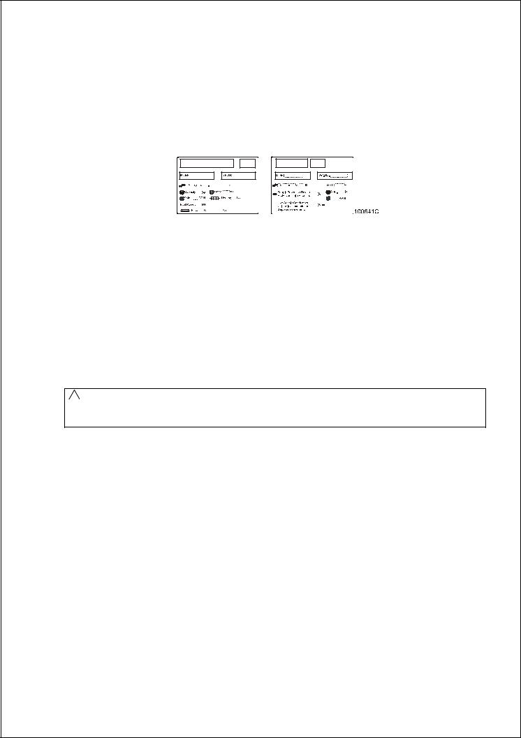
Remove the package as soon as possible and check if the information on the serial plate correspond with your order. The serial plate is located on the rear of the machine, fig.4.1. This determines the type of model you have bought, the voltage and the serial number.
Fig.4.1. Serial plate
Check if the machine is not damaged and if all the accessories are included according to your order. The accessories and manuals are located inside the machine.
4.2. WASHER STORAGE
When the machine will be stored after delivery, be sure this is followed:
-Use the delivered package to protect the machine against moisture and dirt.
-The machine may not be installed within the reach of spraying water.
-Avoid severe climatic storage conditions and excessive humidity. When the temperature changes and this causes damp, you must avoid water under and around the machine and also on his covers.
-If possible, leave the machine in the transporting package or at least let it set on the transporting wooden id until the time of final installation on the foundation according the chapter 4.3. of this manual.
4.3. WASHER POSITIONING
!WARNING!
IF THE MACHINE IS LOCATED ON AN ELEVATED BASE FOR EASIER OPERATION. THE MACHINE SHOULD BE SECURED FOR SAFETY REASONS.
-Before placing the machine on its place, remove the packaging, loosen the rear panel (see fig.4.4., pos.4) and the service panel (pos.3). Remove the four bolts, which holds the machine on the wooden pallet.
Lift up the machine carefully, take care not to damage the machine components.
-Leave at least a 0.6m / 23,6“ free space between the rear panel of machine and the wall. Leave at least a 15 mm / 0.6“ free space between the side panel of the machine and the wall or other machine. Above the machine must be minimum 0.7m / 27.56“ of free space for the maintenance access.
-All passages and spaces the machine has to be transported through at installation should be reasonably dimensioned to meet the height and width of the machine including the package.
-Never push, pull or press the components protruding from the contour line of machine(control panel, door, control elements, water inlet and outlet pipes, etc.).
-Make sure that the loading door is closed during handling.
-Take care that the floor where the machines will be placed is underneath supported. The washer should not be installed on an upper floor or over a basement without approval of structural engineer about the requirements of permissible loading, vibrations and noise level in the building.
-Take care that the floor where the machines will be placed is not combustible.
100646G MAYTAG PUB DATE 28 JUN 2007.DOC |
INSTALLATION AND MAINTENANCE MANUAL |
9 |
FREELY ON THE FLOOR
The machine is to be located on a not elevated leveled concrete floor that comply with static and dynamic stress of the machine.
The friction coefficient must be higher then 0,5 between the rubber feet and the floor material. Do not place the machine on a smooth surface but on a rough floor material like concrete. If the friction coefficient is less, then the machine can move while spinning. If this should happens fasten the machine, see „Fasten withanchoring bolts“.
MACHINES 6kg / 13lb, 7kg / 18lb, 10kg / 25lb
Position the machine only on his 4 adjustable rubber feet.
MACHINES 16kg / 35lb
Place between the four corners of the frame and the floor a thin rubber sheet of 10 x 10 cm / 3.93“ x 3.93“ with thickness between 1-2 mm / 0.04“ - 0.08“ maximum. We advice to fasten this machines always,
see „Fasten with anchoring bolts“.
FREELY ON AN ELEVATION
MACHINES 6kg / 13lb, 7kg / 18lb, 10kg / 25lb
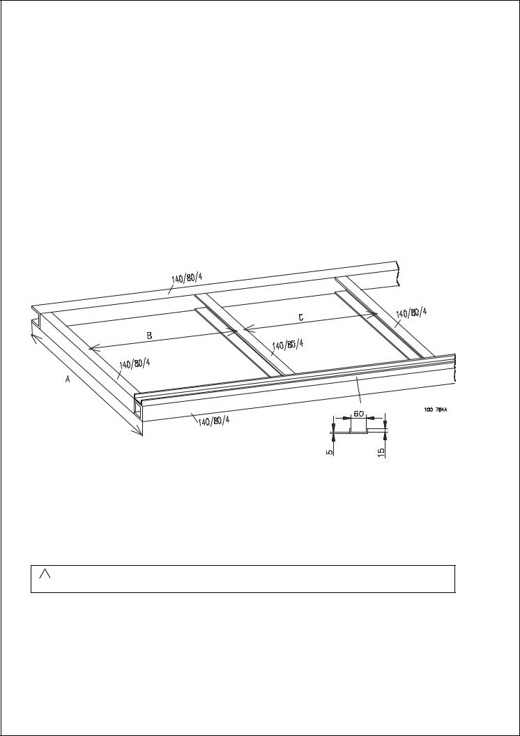
If you choose to place the machine on a metal base or pad, use a U-profile to secure the machine position. Fix the U-profile to the iron frame by welding or fix it to the floor by anchoring bolts. This is necessary to prevent that the machine moves from the base. Make a base according, fig.4.3.A.
Place the machines front rubber feet in the U-profile.
Fig.4.3.A Design of metal base
|
6kg / 13lb |
7kg / 18lb |
|
10kg / 25lb |
Distance A |
660 |
660 |
|
760 |
Distance B |
480 |
480 |
|
480 |
Distance C |
590 |
590 |
|
590 |
|
Tab.4.3.A Frame dimensions |
|
||
! WARNING!
NEVER APPLY THIS FOR A 16 kg / 35 lb MACHINE.
10 |
INSTALLATION AND MAINTENANCE MANUAL |
100646G MAYTAG PUB DATE 28 JUN 2007.DOC |
SECURE ON AN ELEVATION
The machine can also be secured to a mounting base or foundation by means of bolts and anchoring bolts to assure the safety. When a concrete pad or a frame is used then is the maximum height 305 mm / 12“. The pad or frame must be designed so that it can carry the static and dynamic forces. The thickness of iron profiles is minimum 4 mm / 0.158“.
For 6kg / 13lb, 7kg / 18lb, 10kg / 25lb machines, remove the four rubber feeds from the machine frame. Do not tighten anchoring bolts before the concrete base around the bolts is completely secured. Tighten the anchoring bolts with the prescribed torque of the bolts.
1. Bolt M8
2. Securing nut
3. Nut M8
4. Machine frame
5. Washer
6. Elevation frame
7. Concrete floor
8. Anchoring bolt
Fig.4.3.B On an elevation
Fig.4.3.C Frame fixation dimensions
100646G MAYTAG PUB DATE 28 JUN 2007.DOC |
INSTALLATION AND MAINTENANCE MANUAL |
11 |

|
6kg / 13lb |
7kg / 18lb |
10kg / 25lb |
16kg / 35lb |
|
|
|
|
|
|
|
X1 |
660 mm / 25.98“ |
660 mm / 25.98“ |
660 mm / 25.98“ |
830 |
mm / 32.7“ |
X2 |
560 mm / 22.05“ |
560 mm / 22.05“ |
560 mm / 22.05“ |
715 |
mm / 28.1“ |
X3 |
50 mm / 1.97“ |
50 mm / 1.97“ |
50 mm / 1.97“ |
57.5 mm / 2.26“ |
|
X4 |
685 mm / 26.97“ |
685 mm / 26.97“ |
785 mm / 30.91“ |
960 |
mm / 37.8“ |
X5 |
455 mm / 17.91“ |
455 mm / 17.91“ |
565 mm / 22.24“ |
815 mm / 32.09“ |
|
X6 |
130 mm / 5.12“ |
130 mm / 5.12“ |
130 mm / 5.12“ |
80 mm / 3.15“ |
|
X7 |
115 mm / 4.53“ |
115 mm / 4.53“ |
115 mm / 4.53“ |
135 mm / 5.32“ |
|
|
|
Tab.4.3.B Distances anchoring bolts |
|
|
|
LEVELING THE MACHINE
! WARNING!
THE MACHINE MUST RELIABLY REST IN ALL FOUR CORNERS OF THE MACHINE! THE MACHINE MAY NOT ROCK.
THE MACHINE MUST BE IN WATER LEVELLED POSITION.
MACHINES 6kg / 13lb, 7kg / 18lb, 10kg / 25lb
The rubber feet are screwed on the bottom of the machine frame and are adjustable with a wrench size 13 mm / 0.5“ and 17 mm / 0.7“. Check the position of the top of the machine by a water level and adjust machine legs, fig.3., pos.11. Adjust the four rubber feet until the machine is leveled and tighten the nuts M10 back to the bottom of the frame as counter nut.
MACHINES 16kg / 35lb
The 16kg / 36lb machines don’t have rubber feet for adjustment to water level. When it is necessary use thin hard plates of 10 x 10 cm / 3.93“ x 3.93“ with thickness of 1 mm / 0.04“ and place them under the frame corner of the lowest position. Use more of them until the machines stands water level. It is always advisable to bolt down this machine after leveling. Take care that the machine is in the lowest possible position.
If the machine with his cabinet rocks can it damage the machine cabinet. The manufacturer is not responsible for consequences caused by a wrong installation.
4.4. SHIPPING BRACKETS
! WARNING!
DO NOT TRY TO OPERATE THE MACHINE WITHOUT REMOVING THE SHIPPING BRACKETS OTHERWISE THIS CAN LEAD TO INJURY TO PEOPLE AND CAN DAMAGE THE MACHINE. DO NOT TRANSPORT THE MACHINE WITHOUT SHIPPING BRACKETS MOUNTED.
The machine is blocked for transport. This eliminates all possible movement of the tub assembly during transportation. There are 3 striking shipping bars which must be removed before putting the machine into operation.
On each machine is an instruction sheet that shows the location of the shipping brackets.
IMPORTANT: UNSCREW ONLY THE BOLTS-NUTS WHERE INDICATED!
1.Remove shipping bracket front, fig.4.4. pos.1.
2.Remove shipping bracket rear right, fig.4.4. pos.2.
3.Remove shipping bracket rear left, fig.4.4. pos.2.
12 |
INSTALLATION AND MAINTENANCE MANUAL |
100646G MAYTAG PUB DATE 28 JUN 2007.DOC |
 Loading...