


Maytag MFS275PTVS, MFS180PARS, MFS230PTRS, MFS230PAVS, MFS230PARS Installation Instructions
...INSTALLATION INSTRUCTIONS
MFS80, MFS100, MFS125, MFS180, MFS230, MFS275
COMMERCIAL WASHER
TABLE OF CONTENTS
WASHER SAFETY ................................................................... |
2 |
INSTALLATION REQUIREMENTS.......................................... |
3 |
Tools, Parts, and Equipment.................................................. |
3 |
Location Requirements ......................................................... |
3 |
Electrical Requirements......................................................... |
6 |
Water Supply Requirements ................................................. |
7 |
Drain Requirements .............................................................. |
7 |
INSTALLATION INSTRUCTIONS ........................................... |
8 |
Transport, Handling, Inspection, and Storage ...................... |
8 |
Moving to Final Location ....................................................... |
8 |
Water, Drain, and Venting Connections ................................ |
9 |
Electrical Connection .......................................................... |
10 |
Remove Shipping Brackets ................................................ |
13 |
Complete Installation .......................................................... |
15 |
Break-In Period ................................................................... |
15 |
Controls Troubleshooting .................................................... |
15 |
WASHER MAINTENANCE .................................................... |
16 |
Maintenance Schedule........................................................ |
16 |
Vibration Switch Adjustment and Function Test.................. |
17 |
Belt Inspection, Adjustment, and Replacement.................. |
18 |
Tightening Moments............................................................ |
19 |
Lubrication.......................................................................... |
20 |
Water and Steam Filters...................................................... |
20 |
Thrust of Door Seal.............................................................. |
21 |
Spring Unit........................................................................... |
22 |
Fuse Capacities..................................................................... |
22 |
Earth Leakage Trips............................................................... |
22 |
TROUBLESHOOTING.............................................................. |
23 |
REMOVING THE WASHER FROM SERVICE......................... |
24 |
DIMENSIONS AND TECHNICAL SPECIFICATIONS............. |
25 |
Models MFS80, MFS100, and MFS125............................... |
25 |
Dimensions and Connections............................................ |
26 |
Torque Specifications......................................................... |
26 |
Technical Specifications..................................................... |
27 |
Model MFS180...................................................................... |
29 |
Dimensions and Connections............................................ |
30 |
Torque Specifications......................................................... |
30 |
Models MFS230 and MFS275.............................................. |
31 |
Dimensions and Connections............................................ |
32 |
Torque Specifications......................................................... |
32 |
Technical Specifications |
|
(Models MFS180, MFS230, and MFS275)......................... |
33 |
Models MFS230 and MFS275 |
|
with Tilting Feature.............................................................. |
35 |
Dimensions and Connections............................................ |
35 |
Technical Specifications .................................................... |
35 |
W10214569B1
www.maytagcommerciallaundry.com

WASHER SAFETY
IMPORTANT:
■■ This washer must be directly wired to the electrical system and may not be attached with a plug.
■■ The circuit must be a dedicated circuit and may not be combined with any lighting circuit.
■■ Adequate grounding is essential to washer operation.
2
INSTALLATION REQUIREMENTS
Tools, Parts, and Equipment
Read and follow the instructions provided with any tools listed here.
Tools Needed
Washers must be installed by professional installers, who should have a full compliment of standard SAE and metric hand tools, and specialized tools as required. Gather the required tools and parts before starting installation.
Additional Materials
Additional materials may be required for this type of installation and the customer is responsible for supplying additional hardware and adapters as necessary.
Parts Supplied
Remove parts bag from washer drum. Check that all parts were included. The number of parts supplied varies with model.
■■ Molded rubber drain hose and band clamp (2 each) ■■ Rubber washers for the hoses (4)
■■ Water supply hoses (2)
Equipment for Handling, Transport, and Storage
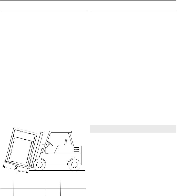
Use a lift truck or a manual skid cart for handling the washer when it still is in the packaging material.
■■ The lift truck forks must be at least 4" (100 mm) longer than the length of the washer frame.
X -
Required Fork Length Chart
X |
80 lbs/100 lbs/125 lbs |
180 lbs |
230 lbs/275 lbs |
|
(33 kg/40 kg/55 kg) |
(80 kg) |
(104 kg/125 kg) |
||
|
||||
Fork |
59" |
71" |
79" |
|
Length |
1500 mm |
1800 mm |
2000 mm |
|
|
|
|
|
■■ If possible, leave the washer in the packaging or on wooden skid until foundation is prepared for installation. Washer is attached to skid by four (4) M-16 bolts.
■■ See “Moving to Final Location” for more information on moving washer to its final location.
Location Requirements
Washers must be installed on a level concrete floor on the ground level of a building. Washers should not be installed on a floor other than the ground floor, or in a room with a basement or on a floor with rooms below without approval of a structural engineer.
Proper installation is your responsibility and must meet all governing codes and ordinances.
Working Conditions
■■ Washers should not be installed within reach of spraying water.
■■ Do not install washer where it will be exposed to weather or excessive humidity. Do not allow water or condensation to run over walls or floor under washer. Ambient temperature for storage or transportation must be between -13 and 131°F (-25 and 55°C).
Floor
Space requirements for installations are determined by the number of washers being installed. See “Technical
Specifications” and “Installation Instructions” for more detailed information.
■■ Installation must be on a solid concrete floor or slab capable of withstanding the weight and vibration produced by the washer. The maximum slope of the floor is 1° under the washer. A rough, uncovered concrete surface is preferable to a smooth or covered surface.
Weight of Washers
Weight on |
80 lbs |
100 lbs |
125 lbs |
180 lbs |
230 lbs |
275 lbs |
floor |
33 kg |
40 kg |
55 kg |
80 kg |
104 kg |
125 kg |
|
|
|
|
|
|
|
Maximum |
3239 lbs |
4083 lbs |
4400 lbs |
7144 lbs |
– |
– |
static load |
1469 kg |
1852 kg |
1996 kg |
3241 kg |
|
|
(with linen and |
|
|
|
|
|
|
water) |
|
|
|
|
|
|
|
|
|
|
|
|
|
Maximum |
2855 lbs |
3615 lbs |
3835 lbs |
6176 lbs |
– |
– |
dynamic |
1295 kg |
1640 kg |
1740 kg |
2801 kg |
|
|
load (alt. |
+616 lbs |
+661 lbs |
+704 lbs |
+1511 lbs |
|
|
stress when |
+279 kg |
+300 kg |
+319 kg |
+685 kg |
|
|
extracting) |
|
|
||||
|
|
|
|
|
|
|
|
|
|
|
|
|
|
Dynamic |
14.0 Hz |
14.0 Hz |
14.0 Hz |
12.5 Hz |
– |
– |
load |
|
|
|
|
|
|
frequency |
|
|
|
|
|
|
■■ Washer must be secured with four (4) M16 x 160 mm anchoring bolts. Install all four anchors before final installation of the washer. Apply a torque of 210 Nm/ 155 ft. lbs.
■■ Washer will be firmly secured to the floor and all four (4) footings must touch the floor.
■■ Allow for adequate sanitary sewer drainage, located behind the washers.
Water and Electric
■■ A hot water heater set at 158°F (70°C).
■■ 1" (25 mm) inlet valves for hot and cold water. Determine water hardness levels. Hard or medium levels may require a water softener.
■■ A dedicated, GFCI-equipped circuit for each washer (see “Electrical Requirements”).
3

Spacing
■■ Washers require 2.4 ft (0.7 m) above the top for maintenance.
■■ Washers require 2.4 ft (0.7 m) (Models MFS80/MFS100/ MFS125) and 2.6 ft (0.8 m) (Models MFS180/MFS230/ MFS275) between the sides for maintenance and maximum door clearance.
■■ Allow 3.3 ft (1 m) behind washer and the wall for maintenance.
Models MFS80, MFS100, MFS125
28".3 ft
(711(0.mm)7 m)
|
|
|
|
|
|
|
|
|
|
|
|
|
|
|
|
|
|
|
|
|
|
|
|
|
|
|
|
|
|
|
|
|
|
|
|
|
|
|
|
|
|
|
|
|
|
|
|
|
|
|
|
|
|
|
|
|
|
|
|
|
|
|
|
|
|
|
|
|
|
|
|
|
|
|
|
|
|
|
|
|
|
|
|
|
|
|
|
|
|
|
|
|
|
|
|
|
|
|
|
|
|
|
|
|
|
|
|
|
|
|
|
|
|
|
|
|
|
|
|
|
|
|
|
|
|
|
|
|
|
|
|
|
|
|
|
|
|
|
|
|
|
|
|
|
|
|
|
|
|
|
|
|
|
|
|
|
|
|
|
|
|
|
|
|
|
|
|
|
|
|
|
|
2.3 ft |
2.3 ftP |
|
|
|
|
|
|
|
|
|
|
|
|
|
|
|
|
|
|
|
|
|
|
|
|
|
|
||
|
|
|
|
|
|
|
|
|
|
|
|
|
|
|
|
|
|
|
|
|
|
|
|
|
|
(0P.7 m) |
||
|
|
|
|
|
|
|
|
|
|
|
|
|
|
|
|
|
|
|
|
|
|
|||||||
(0.7 m) |
|
|
|
|
|
|
|
|
|
|
|
|
|
|
|
|
|
|
|
|
|
|
|
|
|
|
||
|
|
|
|
|
|
|
|
|
|
|
|
|
|
|
|
|
|
|
|
|
|
|
|
|
|
|
|
|
Front View
<![if ! IE]><![endif]>700 mm 28"
40"
1000 mm
X3 1
2
Side View |
X11 |
|
|
X10 |
3 |
1. |
Drain with elbow |
X9 |
|
2. |
Cover of waste pump |
|
|
3. |
Waste sump |
|
|
|
|
Dimensions |
|
|
|
|
X3 |
46.25" (1175 mm) |
|
X9 |
14" (350 mm) |
|
X10 |
12" (300 mm) |
|
X11 |
9" (250 mm) |
4
Spacing Between Multiple Washers and Feet Placement
Models MFS80, MFS100, MFS125
1 |
<![if ! IE]> <![endif]>X4 |
|
3 |
|
2 |
X12 |
|||
|
||||
|
|
|
||
|
|
|
<![if ! IE]> <![endif]>X13 |
|
| <![if ! IE]> <![endif]>mm 28" |
|
|
4 |
|
X1 |
|
X15 |
||
X6 |
|
|||
| <![if ! IE]> <![endif]>X5 700 |
|
|
|
|
|
|
|
<![if ! IE]> <![endif]>X14 |
|
| <![if ! IE]> <![endif]>X2 |
|
|
|
|
|
|
|
X16 |
|
|
|
|
X17 |
1.Washer contour line
2.Washer foot
3.Waste sump
4.Drain with elbow
Feet Placement
Distance |
MS80 |
|
MS100 |
|
MS125 |
X1 |
38.19" |
|
42.13" |
|
49.21" |
|
(970 mm) |
|
(1070 mm) |
(1250 mm) |
|
Distance |
|
|
All Models |
|
|
X2 |
36.61" (930 mm) |
||||
X4 |
|
32.7" (830 mm) |
|
||
X5 |
|
5.12" (130 mm) |
|
||
X6 |
|
3.03" (77 mm) |
|
||
X12 |
|
|
8" (200 mm) |
|
|
X13 |
|
|
9" (250 mm) |
|
|
X14 |
|
29.5" (750 mm) |
|
||
|
|
|
|
|
|
X15 |
|
|
6" (150 mm) |
|
|
X16 |
|
|
7" (180 mm) |
|
|
|
|
|
|
|
|
X17 |
|
|
8" (200 mm) |
|
|
|
|
|
|
|
|
Models MFS180, MFS230, MFS275 |
|
Spacing Between Multiple Washers and Feet Placement |
||||||||||||||
|
|
|
|
|
|
|
|
|
|
|
|
|
|
|
Models MFS180, MFS230, MFS275 |
|
|
|
|
|
|
|
|
|
|
|
|
28".3 ft |
|
|
|||
|
|
|
|
|
|
|
|
|
|
|
|
|
||||
|
|
|
|
|
|
|
|
|
|
(711(0.mm)7 m) |
|
|
|
|
||
|
|
|
|
|
|
|
|
|
|
|
|
|||||
|
|
|
|
|
|
|
|
|
|
|
|
|
|
|
|
|
|
|
|
|
|
|
|
|
|
|
|
|
|
|
|
|
|
|
|
|
|
|
|
|
|
|
|
|
|
|
|
|
|
|
|
|
|
|
|
|
|
|
|
|
|
|
|
|
|
|
|
|
|
|
|
|
|
|
|
|
|
|
|
|
|
|
|
|
|
|
|
|
|
|
|
|
|
|
|
|
|
|
|
|
|
|
|
|
|
|
|
|
|
|
|
|
|
|
|
|
|
|
|
|
|
|
|
|
|
|
|
|
|
|
|
|
|
|
|
|
|
|
|
|
|
|
|
|
|
|
|
|
|
|
|
|
|
|
|
|
|
|
|
|
|
|
|
|
|
|
|
|
|
|
|
|
|
|
|
|
|
|
2.6 ft |
2.6 ftP |
|
|
|
|
|
|
|
|
|
|
|
|
|
|
|
|
|
|
|
|
|
|
|
|
|
|
|
|
|
|
|
|
|
|
|
|
|
|
|
|
|
(0P.8 m) |
|
|
|
|
|
|
|
|
|
|
|
|
|
|
|
|
|
||||||
(0.8 m) |
|
|
|
|
|
|
|
|
|
|
|
|
|
|
|
|
|
|
|
|
|
|
|
|
|
|
|
|
|
|
|
|
|
|
|
|
|
|
|
|
|
|
|
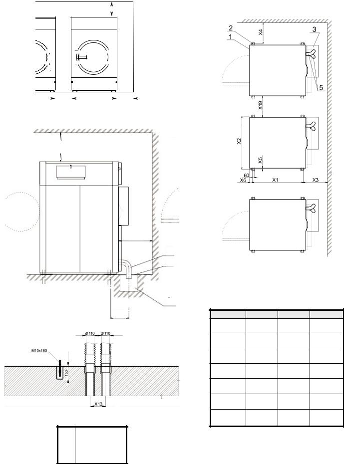
Front View
X1
X2
1
2
1. Washer contour line
2. Washer foot
3. Waste sump
Side View 4. Drain hose
Side View
1. Drain hose |
|
3 |
Feet Placement |
|
|
|
|
|
|||
|
|
|
|
|
|
2. Waste sump cover |
X3 |
Distance |
MS180 |
MS230 |
MS275 |
3. Waste sump |
|
X1 |
49.99" |
54.64" |
55.11" |
|
|
||||
|
|
|
(1270 mm) (1388 mm) (1400 mm) |
||
|
|
X2 |
56.29" |
67.51" |
70.07" |
|
|
|
(1430 mm) (1715 mm) (1780 mm) |
||
|
|
X3 |
41.92" |
52.44" |
52.44"" |
|
|
|
(1065 mm) (1332 mm) (1332 mm) |
||
|
|
X4 |
30.70" |
30.70" |
30.70" |
|
|
|
(780 mm) |
(780 mm) |
(780 mm) |
|
|
X5 |
0.78" |
0.53" |
0.59" |
|
|
|
(20 mm) |
(13.50 mm) |
(15 mm) |
|
|
X6 |
5.9" |
5.11" |
5.19" |
|
|
|
(150 mm) |
(130 mm) |
(132 mm) |
|
|
X19 |
27.55" |
31.49" |
31.49" |
Dimensions |
|
|
(700 mm) |
(800 mm) |
(800 mm) |
X1 |
27.55" (700 mm) |
|
|
|
X2 |
39.36" (1000 mm) |
|
|
|
Product Dimensions |
||||
X3 |
16.33" (415 mm) |
|
||
See “Technical Specifications” for specific measurements on |
||||
|
|
|
||
X13 |
9.84" (250 mm) |
|||
each washer size. |
||||
|
|
|
||
5

Electrical Requirements
It Is Your Responsibility:
■■ To contact a qualified electrical installer.
■■ To be sure that the electrical connection is adequate and in conformance with the National Electrical Code, ANSI/NFPA 70-latest edition, or Canadian Electrical Code CSA C22.1, and all local codes and ordinances.
A copy of the above code standards can be obtained from:
National Fire Protection Association, One Batterymarch Park,Quincy, MA 02269.
■■ To supply the required 3 or 4 wire, three-phase, 208–240 volt, 50/60 Hz., AC electrical supply on a separate circuit. Circuit capacity is dependent on washer size and connection type and is shown in the table below. A time-delay fuse
or circuit breaker is recommended. Installation of a GFCI (Ground Fault Circuit Interrupter) is also recommended. Connect to an individual branch circuit. Do not fuse the neutral or grounding circuit.
Electrical Connection
 WARNING
The electrical connections were designed per the specifications provided during the ordering process. Before connecting, verify the voltage and frequency on the washer label. See the Back View in “Dimensions and Technical Specifications” to ensure that the voltage and frequency correspond to your power network. The connection is described in the illustration below. If the washer is not equipped with a main switch, power disconnects are needed for all electrical supplies connected to the washer,
in accordance with item 5.3 in standard EN 60204-1.
Washer Connection to Electrical Network (With an Earth Leakage Trip)
1.Earth leakage trip
2.Laundry electrical
|
main switch |
|
3. |
Power supply protection |
1 |
4. |
Washer |
|
5. |
Phase conductors |
|
6. |
Protective conductor |
2 |
7. |
Main switch inlet terminal |
|
|
switchboard |
3 |
8. |
Neutral conductor |
|
|
|
4 |
|
|
5 |
|
|
6 |
|
|
7 |
|
|
8 |
Inlet Conductors and Power Supply Protection
Inlet conductors of the washer connection to the electrical network must have copper cores. The cross section of the inlet conductors depends on the voltage and the unit heating type, i.e. total electrical input. Circuit breakers or fuses in the laundry switchboard keep the inlet cable from short-circuiting and overloading.
Manufacturer’s Recommended Minimal Conductor Section
Power supply |
Min. phase |
Min. protective |
|
protection device |
conductor |
conductor |
|
nominal |
section in mm2 |
section in mm2 |
|
current (US) |
(AWG) |
(AWG) |
|
Automatic |
|
|
|
circuit |
|
|
|
breakers |
Fuses |
|
|
16A (15A) |
10A (10A) |
1.5 mm2 (AWG 15) |
1.5 mm2 (AWG 15) |
20A (20A) |
16A (15A) |
2.5 mm2 (AWG 13) |
2.5 mm2 (AWG 13) |
25A (–) |
20A (20A) |
4 mm2 (AWG 11) |
4 mm2 (AWG 11) |
40A (40A) |
32A (30A) |
6 mm2 (AWG 9) |
6 mm2 (AWG 9) |
63A (–) |
50A (50A) |
10 mm2 (AWG 7) |
10 mm2 (AWG 7) |
80A |
63A |
16 mm2 |
16 mm2 |
100A |
80A |
25 mm2 |
16 mm2 |
125A |
100A |
35 mm2 |
25 mm2 |
See “Technical Specifications” for the corresponding current.
■■ A separate grounding wire is recommended if codes permit. It is recommended that a qualified electrician determine the grounding path is adequate.
NOTE: Connecting these washers to an IT power supply requires special consideration.
6

Connection of the Main Power Inlet
1
2
3
1.Main switch
2.Strain relief
3.Sag of inlet cable
Connection to Washer
These washers were designed for direct wiring into the power supply. The washer must be electrically grounded in accordance with all local codes or, in the absence of local codes, with the National Electrical Code, ANSI/NFPA 70, latest edition,
or Canadian Electrical Code, CSA C22.1.
Direct Wire Installation:
Power supply cable must match power supply (4-wire or 3-wire) and be:
■■ Flexible armored cable or nonmetallic sheathed copper cable (with grounding wire), in a flexible metallic conduit, to avoid conductor breakage due to vibration. All current-carrying wires must be insulated.
■■ Copper wire of appropriate gauge for amperage requirement (see “Manufacturer’s Recommended Minimal Conductor Section”). Stranded wire is recommended. Do not use aluminum wire.
Equipotential bonding:
In addition to an equipment-grounding conductor that must be run with the circuit conductor and be connected to the equipment grounding terminal, all washers or appliances in the vicinity must be permanently interconnected with a connector.
The external connection points serve for this purpose. See illustration below.
The cross-sectional area of the conductor must be at least electrically equivalent to the cross-sectional area of the copper conductor.
3 |
3 |
4 |
3 |
2 |
|
3
1
1.Protective grounding structure
2.External protective conductor connection point
3.Protective conductor
4.Grounding identification
Water Supply Requirements
Water supply requirements are as follows:
■■ Valved hot and cold water supply with a water pressure between 14.5 and 116 PSI (100–800 kPa). Water pressure between 43 and 73 PSI (300–500 kPa) is recommended.
■■ A hot water heater or boiler supplying an adequate amount of water between 120–160°F (49–80°C). The water temperature within the washer is controlled to a maximum temperature that is set in the program. The amount of hot water required to wash a load of laundry is dependent on many factors, including the hot and cold water temperature and the wash program selected. Average amounts of hot water required to wash one load of laundry are shown in the table below.
Hot Water Requirement Per Load |
|
|
|
Washer Model |
Hot water per load* |
|
|
MFS80 |
60 gal. (227 L) |
MFS100 |
70 gal. (265 L) |
MFS125 |
80 gal. (303 L) |
|
|
MFS180 |
– |
|
|
MFS230 |
– |
|
|
MFS275 |
– |
|
|
*Approximate values. Assumes 140°F (60°C) hot water supply and 70°F (21°C) cold water supply.
Drain Requirements
The washers have two 3" (76 mm) water drains on their rear side. To connect the drains to a drain hose, use the 3" (76 mm) elbow which is supplied with the washer. Secure the elbow with a clamp. To maintain washer performance, do not reduce the diameter of the drain pipe.
The washer may drain into a waste channel or directly to a drain.
■■ The waste channel cannot be located under the washer. There should be at least 4" (102 mm) between the back of the washer and the middle of the waste channel (see illustration below).
■■ The waste channel must be lower than the drain pipe. There should be at least a 3/4" (19 mm) air gap between the bottom of the drain and the water level in the channel.
X
|
4" |
|
|
|
|
|
|
|
|
|
|
|
|
|
|
|
|
|
|
|
|
|
|
|
|
|
|
|
|
|
|
|
|
|
|
|
|
|
|
|
|
|
|
|
|
|
|
|
|
|
|
|
|
|
|
|
|
|
|
|
|
|
|
|
|
|
|
|
|
|
|
|
|
|
|
|
|
|
|
|
|
|
|
|
|
|
|
|
|
|
|
|
|
|
|
|
|
|
|
|
|
|
|
|
|
|
|
|
|
|
|
|
|
|
|
|
|
|
|
|
|
|
|
|
|
|
|
|
|
|
|
|
|
|
|
|
|
|
|
|
|
|
|
|
|
|
|
3/4" |
|
|
|||
|
|
|
|
|
|||||||||
|
|
|
|
|
|
|
|
||||||
|
(102 mm) |
|
|
|
|
|
(19 mm) |
||||||
|
Minimum Waste Channel Measurements |
||||||||||||
|
|
|
|
|
|
|
|
|
|
|
|
|
|
|
MFS80/100/125 |
MFS180/230/275 |
|||||||||||
|
|
|
|
|
|
|
|
|
|
|
|
|
|
X |
4" |
|
|
4" |
|
|
|
|
|||||
|
(102 mm) |
|
|
(102 mm) |
|||||||||
7

INSTALLATION INSTRUCTIONS
Transport, Handling, Inspection, and Storage Models MFS80, MFS100, MFS125
NOTE: Refer to "Equipment for Handling, Transport, and Storage" under "Tools, Parts, and Equipment" for proper handling of washer.
1.Inspect carton for damage. Inspect washer if carton shows signs of damage. Do not remove washer from pallet.
2.Verify model number and serial number on the data plate with your order.
Remove accessories and manuals from inside washer drum.
3. Store inside in a temperature controlled |
|
environment -13° and 131°F (-25° and |
|
55°C). Do not expose washer to the |
|
weather. Humidity levels must be |
Data Plate |
between 30 to 90% without condensation. |
IMPORTANT: Make sure that all components are secured during transportation and installation.
Moving to Final Location
IMPORTANT:
■■ Make sure all passages and spaces through which the washer will be moved to its installation location are high enough and wide enough for the washer and its packaging.
■■ Do not push, pull, or press the parts protruding from the washer (front section, door, control panel, belt cover, water inlet, outlet pipes, etc.).
■■ To avoid damage during handling and installation, make sure all protruding parts are secured.
1.Move the washer near the point of installation with a lift truck and remove packing material.
2.Loosen the 4 - M16 x 160 mm bolts attaching the washer to the pallet and gently lift washer.
IMPORTANT: Washer is very heavy. Consider equipment and manpower required to move this washer prior to installation and be sure that all necessary preparations are made.
Fastening Washer to Concrete Floor
1.Washer is to be attached to the concrete floor with anchor bolts. All four footings must come into firm contact with the floor.
2.Level washer’s base frame with a level.
3.Do not tighten nuts of the anchor bolts until the concrete floor or base has completely cured.
4.Tighten the nuts of the anchoring bolts to a maximum
155 lbf.ft/210 Nm for the bolts on Models MFS80, MFS100, and MFS125. For Models MFS180, MFS230, and MFS275 tighten the nuts of the anchoring bolts to a maximum of
36 lbf.ft/49 Nm.
5.See “Dimensions and Technical Specifications” section for installation measurements.
4
2
|
|
|
|
|
|
|
|
|
|
|
|
|
|
|
|
|
|
|
2 - Washer foot |
||
|
|
|
|
|
|
|
|
4- Anchoring bolt |
||
|
|
|
|
|
|
|
|
|
|
|
|
|
Bolt Dimensions |
||||||||
|
|
|
|
|
|
|||||
X7 |
|
|
|
1.57" (40 mm) |
|
|
||||
X8 |
|
|
|
5.9" (150 mm) |
|
|
||||
|
|
|
|
|
|
|
|
|
|
|
Models MFS180, MFS230, MFS275
1
2
X8
1- Anchoring bolt
2 - Washer foot
|
|
X7 |
|
|
|
|
|
||
|
|
|
||
|
Bolt Dimensions |
|||
|
|
|
|
|
X7 |
|
2.36" (60 mm) |
||
X8 |
|
6.3" (160 mm) |
||
|
|
|
|
|
8

Water, Drain, and Venting Connections
Water Hardness
Determine the water hardness level in water supply. Good wash results are dependent on water hardness. In areas that have medium and very hard water levels, a water softener may be required. Contact your water or soap distributor for determining the proper soap and detergents to be used with your hardness levels for the best wash results.
Water Supply Connections
Washers have 2 water inlets. For connection dimensions, see “Dimensions and Technical Specifications.”
1.Always use the flexible hoses delivered with the washer. Do not use a fixed connection to the water supply.
2.Keep proper water pressure within range. See “Dimensions and Technical Specifications.”
3.Connect all water inlets to a water supply. Contact your dealer if there is no hot water supply available.
4.1" (25 mm) or 1.5" (38 mm) Inlet valves for hot and cold water use inlet pressure hoses with gaskets. Mount shut-off valves to the water supply pipes for cleaning filters and performing maintenance.
5.To connect the washer to the water inlet shut-off valves, use the provided flexible hoses.
Steam Connections
Washer with steam heating is equipped with an outer thread
in the back of the washer for connection with the washer steam line. See “Dimensions and Technical Specifications” for more details.
IMPORTANT:
■■ Install a steam supply disconnecting device near each washer.
■■ Inlet value of steam pressure must be within range. Any other pressure may result in washer not functioning properly.
■■ To avoid possible injuries, shut off the main steam inlet and let the parts cool down after connection.
■■ Insert a filter with permeability up to 300 micrometers in front of every steam valve. Dirt particles larger than 300 micrometers can damage the steam valve and cause leakage.
■■ Attach steam filter to the washer at the connection point. The supply piping must be clean without dirt and rust particles. Impurities in the supply line can cause steam valves to fail.
■■ Do not twist the filter gasket when connecting the pipes. To shut off the assembly, clamp the filter at the side of the connecting pipe.
Drain Connections
MFS80, MFS100, and MFS125 washers are equipped with two 3" (75 mm) diameter drain pipes. MFS180, MFS230, and MFS275 washers are equipped with two 4" (100 mm) diameter drain pipes. See “Dimensions and Technical Specifications” for location. Both pipes must be connected to the waste sump.
The sump must be positioned lower than the drain, because the washer uses gravity to discharge water. Use the provided drain hose to connect drain pipes to sump. Secure with a clamp and properly cover sump. The capacity of discharged water for each washer model is 300.00 dm3/min and 80.00 gal/min for the 3" drain. For the 4" drains, the capacity of discharged water for each washer model is 540.00 dm3/min and 142.00 gal/min.
Recycled Water Drain Connection (some models)
Attach connecting hoses to the discharging valve located on the right side (from rear view). The hoses go to your recycling tank located below the drainage valve. The tank must be large enough for the total weight and volume of water and made up of
materials which withstand 176°F (80°C) and the effects of laundry soap. The quantity of water will vary by washer size and cycle.
Venting
IMPORTANT: To maintain proper venting, do not cover the washer vent.
Although not recommended, it is possible to connect vent to the laundry central exhaust ducts. Venting materials must withstand a temperature of 176°F (80°C). Always use flexible vent material if a connection is made. The central vent for multiple washers must be dimensioned for the total cross section of all vents and washers. Calibrate washer’s “zero” level after vent has been attached.
9
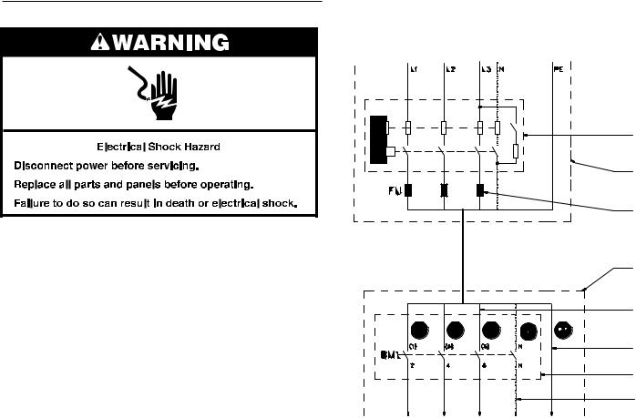
Electrical Connection
Washer Connection to Electrical Network (with a residual current device)
Check the data plate to determine electrical requirements. Before making the electrical connection, make sure the voltage and frequency listed on the data plate matches your electrical network. Each washer must be on an individual branch circuit. To ensure uninterrupted electrical current, a residual current device
(RCD) and a circuit breaker must be installed in the building’s electrical system for each washer. The proper connection is
described in the illustration on the right.
IMPORTANT:
■■ If the washer is not equipped with a main switch, supply
disconnecting devices need to be installed in accordance with EN 60204-1 standard 5.3.
■■ Make sure the supply voltage is always within the limits specified in “Technical Specifications.” If the electrical installation requires long distances to travel, it may be
necessary to use larger cables to reduce the voltage drop. 1. Residual current device (RCD) 2. Laundry electrical main switch 3. Power supply protection
4. Washer
5. Phase conductors
6. Protective conductor
7. Main switch inlet terminal
8. Neutral conductor
1
2
3
4
5
6
7
8
10
Residual Current Device (RCD)
In some countries an RCD is known as an “earth leakage trip,” “Ground Fault Circuit Interrupter” (GFCI), “Appliance Leakage Current Interrupter” (ALCI), or “earth (ground) leakage current breaker.”
Specifications:
■■ Tripping current: 100mA (if locally not available/allowed use a 30mA trip current, preferably selective type with small time delay set).
■■ Install a maximum of two (2) washers on each RCD (for 30mA, only one (1) washer)
■■ Type B. There are components inside the washer which use DC-voltages, making a “Type B” RCD necessary.
NOTE: Type B performs better than Type A, and Type A is better than Type AC.
When locally allowed, an RCD must always be installed. In some electrical network earthing systems (IT, TN-C,…), an RCD might not be allowed (see also IEC 60364).
The washer control circuits are mostly supplied by a separating transformer. Therefore, the RCD may not detect faults in the control circuits (but the fuse(s) of the separating transformer will).
Supply Protection Device
A supply protection device keeps the washer and wiring from experiencing overloads and short circuits. As a supply protection device, you can use either glow-wire fuses or automatic circuit breakers. See “Technical Specifications” for the rating of the nominal current and other specifications of the supply protection device. This table specifies that protection must be the “slow” type, curve D for circuit breakers. Although not recommended,
if you cannot use a “slow” type, select the protection device with one (1) step higher nominal current rating to avoid disconnecting during start-up.
Supply Cable
The supply cable is not delivered with the washer.
Specifications:
■■ Use conductors with copper cores.
■■ Stranded conductors (flexible wiring) are strongly recommended to avoid conductor breaking due to vibration.
■■ The cross section depends on the used supply protection device. See “Manufacturer’s Recommended Minimal Conductor Section” in “Electrical Requirements” for the minimal cross section.
■■ The cable should be as short as possible, directly across from the supply protection device to the washer without branching off.
■■ Do not use a plug or extension cords; the washer is intended to be permanently connected to the electrical network.
Connection:
■■ Insert the cable through the hole on the rear panel. Use a strain relief to secure the supply cable.
■■ Strip the conductor ends according to “Adaptation of Conductor Ends of Supply Cable” illustration on the right.
■■ The protective conductor must be longer to ensure it is the last one disconnected if the cable is pulled out unintentionally.
■■ With stranded conductors, it is recommended to use “wire-end tubes” with an insulated sleeve (6) for L1/U, (L2/V), (L3/W), (N) conductors. Make sure there cannot be unintentional contact, since the supply cable stays under voltage even when the main switch is off.
■■ Crimp a ring terminal (eyelet) to the protective conductor for good connection to the PE terminal.
■■ Connect the supply cable conductors to the terminals (main switch [1]) marked with L1/U, (L2/V), (L3/W), (N), and the terminal (copper screw) marked with PE.
See “Main Power Inlet Connection” illustration below.
■■ Provide a sag in the cable, in front of the cable strain relief. This will stop condensed water from entering the washer. See “Main Power Inlet Connection” illustration below.
Adaptation of Conductor Ends of Supply Cable
1. |
Protective conductor |
5. |
Neutral conductor |
2. |
Phase conductor |
6. |
Wire-end tube |
3. |
Phase conductor |
7. |
The stripped length of |
4. |
Phase conductor |
|
conductors |
Main Power Inlet Connection
1. Main switch
2. Strain relief
3. Sag of inlet cable
1
2
3
11
 Loading...