


ATB2130AR series
Maytag ATB2130AR series, ATB1836AR series, ATB1838AE series, ATB1830AR series, ATB2136AR series Service Manual
...
Service
This manual is to be used by qualified appliance
technicians only. Maytag does not assume any
responsibility for property damage or personal
injury for improper service procedures done by
an unqualified person.
18 & 21
Cubic Foot
Top Mount
Refrigerators
This Base Manual covers general information
Refer to individual Technical Sheet
for information on specific models
This manual includes, but is
not limited to the following:
ATB1821AR*
ATB1830AR*
ATB1836AR*
ATB1838AE*
ATB1832AR*
ATB2130AR*
ATB2132AR*
ATB2136AR*
ATB2138AR*
ATF2136AR*
ATF2138AR*
CTB1821AR*
CTN1821AE*
CTL1821AE*
CTB2121AR*
CTF2126AR*
MTB1891AR*
MTB1893AR*
MTB1895AE*
MTB2193AR*
MTB2195AR*
MTF2193AR*
MTF2195AE*
16025860
Replaces 16023446
January 2005

!
!
!
!
Important Information
Important Notices for Servicers and Consumers
Maytag will not be responsible for personal injury or property damage from improper service procedures. Pride and
workmanship go into every product to provide our customers with quality products. It is possible, however , that
during its lifetime a product may require service. Products should be serviced only by a qualified service technician
who is familiar with the safety procedures required in the repair and who is equipped with the proper tools, parts,
testing instruments and the appropriate service information. IT IS THE TECHNICIANS RESPONSIBILITY TO
REVIEW ALL APPROPRIATE SERVICE INFORMATION BEFORE BEGINNING REPAIRS.
WARNING
To avoid risk of severe personal injury or death, disconnect power before working/servicing on appliance to avoid
electrical shock.
To locate an authorized servicer, please consult your telephone book or the dealer from whom you purchased this
product. For further assistance, please contact:
Customer Service Support Center
CAIR Center
Web Site Telephone Number
WWW.AMANA.COM ............................................... 1-800-843-0304
WWW.JENNAIR.COM ............................................ 1-800-536-6247
WWW.MAYTAG.COM............................................. 1-800-688-9900
CAIR Center in Canada..........................................1-800-688-2002
Amana Canada Product .... ....... ....... ........................ 1-866-587-2002
Recognize Safety Symbols, Words, and Labels
DANGER
DANGER—Immediate hazards which WILL result in severe personal injury or death.
WARNING
WARNING—Hazards or unsafe practices which COULD result in severe personal injury or death.
CAUTION
CAUTION—Hazards or unsafe practices which COULD result in minor personal injury, product or property
damage.
16025860 2 ©2005 Maytag Services

Table of Contents
Important Information ................................................. 2
Model Identification.................................................... 4
Component Testing
Compressor ............................................................ 5
Resistance Test .......................................................5
Ground Test............................................................. 5
Operation T est......................................................... 5
Capacitor................................................................. 6
Condenser...............................................................6
Overload / Relay...................................................... 7
Temperature Control ............................................... 7
Ice Maker ................................................................ 7
Condenser Motor.....................................................7
Evaporator Fan Motor ............................................. 7
Upper Freezer Light Switch .....................................8
Drier ........................................................................ 8
Defrost Timer .......................................................... 8
Evaporator............................................................... 9
Defrost Heater......................................................... 9
Defrost Thermostat ................................................. 9
Service Procedures
Service Equipment ................................................ 10
Drier Replacement ................................................ 10
Refrigerant Precautions............................................ 11
Line Piercing V alves .............................................. 11
Open Lines............................................................ 11
Compressor Operational Test................................ 11
Dehydrating Sealed Refrigeration System ............. 12
Leak Testing .......................................................... 12
Restrictions ...........................................................13
Evacuation and Charging ......................................... 14
Evacuation ............................................................ 14
Charging................................................................ 15
Refrigerant Charge ...................................................15
HFC134a Service Information .................................. 16
Health, Safety , and Handling ................................. 16
Comparison of CFC12 and HFC134a Properties .. 16
Replacement Service Compressor ..........................17
Compressor Testing Procedures ........................... 17
Refrigerant Flow ....................................................... 18
Cabinet Air Flow ....................................................... 19
Troubleshooting Chart .........................................20-22
System Diagnosis
Symptoms of an Overcharge................................. 23
Symptoms of Refrigeration Shortage.....................23
Symptoms of a Restriction .................................... 24
Symptoms of Air in System ................................... 24
Symptoms of Low or High Ambient ....................... 25
T emperature Installation........................................ 25
Heat Load..............................................................25
Disassembly Procedures
Door Removal
Freezer Door .........................................................26
Fresh Food Door ................................................... 26
Refrigerator Compartment
Light Bulb .............................................................. 27
Light Bulb Assembly.............................................. 27
Defrost Timer ........................................................ 27
Light Switch ...........................................................27
Cold Control .......................................................... 27
Freezer Compartment
Evaporator Cover .................................................. 27
Freezer T emperature Control ................................ 27
Evaporator Fan, Evaporator Motor ........................ 27
Defrost Terminator (Thermostat) ........................... 27
Defrost Heater....................................................... 27
Evaporator Removal.............................................. 28
Bottom of Cabinet
Front Roller Assembly ........................................... 28
Rear Roller Assembly............................................ 28
Condensate Drain Pan .......................................... 28
Machine Compartment
Condenser Fan & Fan Motor .................................28
Compressor .......................................................... 28
Overload/Relay/Capacitor......................................28
Condensate Drain Tube ........................................ 28
Condenser Removal.............................................. 28
Appendix A
Ice Maker Service Instructions ............................ A-2
Appendix B
Owners Manual ................................................... B-2
©2005 Maytag Services 3 16025860
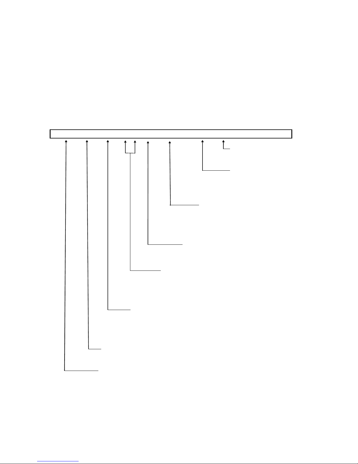
Model Identification
Top Mount Refrigerator models vary in trim and
accessories, but all models have the same basic
construction. "Operating Instructions" and "Service
Instructions" apply to all cabinets unless stated
otherwise.
A T B 1 8 0 4 A R W
R = Regular
E = Energy Model
Brand
A = Amana
M = Maytag
` C = Magic Chef
Product
T ⎯ Top M ount
16025860 4 ©2005 Maytag Services
For positive identifications of individual units, state
complete serial number, model, and type. This
information is found on the serial plate located on front
upper right hand corner of foodliner or on some
models, exterior back of the outer casing.
An explanation of coding contained in Type position is
shown below.
Model Identification
Color
W ⎯ White
Q ⎯ B isque
Energy
Feature Package
1 - 3 ⎯ Good
4 - 6 ⎯ Better
7 ⎯ Best
Special Features
0 ⎯ Brand Base
Capacity
18 or 21 ⎯ C ubic Foot
Configuration
B ⎯ P rovisional
L ⎯ Left H and (Non P rovisional)
N ⎯ Right Hand(N on Provisional)
Component Testing
!
WARNING
To avoid risk of electrical shock, personal injury, or death, disconnect electrical power source to unit, unless test
procedures require power to be connected. Discharge capacitor through a resistor before attempting to service.
Ensure all ground wires are connected before certifying unit as repaired and/or operational.
Component Description Test Procedures
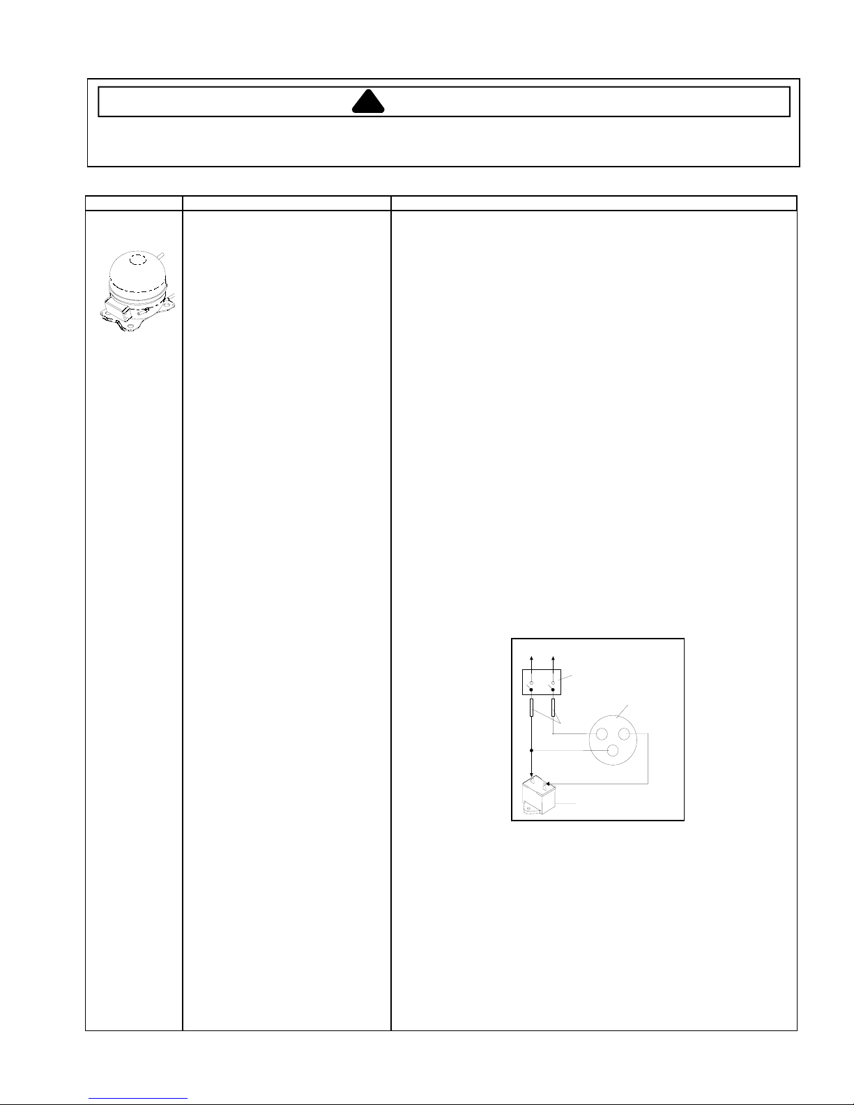
Compressor
When compressor electrical circuit is
energized, the start winding current
causes relay to heat. After an amount of
starting time, the start winding circuit
turns off. The relay will switch off the start
winding circuit even though compressor
has not started (for example, when
attempting to restart after momentary
power interruption).
With “open” relay, compressor will not
start because there is little or no current
to start windings. Overload protection will
open due to high locked rotor run winding
current.
With “shorted” relay or capacitor,
compressor will start and overload
protector will quickly open due to high
current of combined run and start
windings.
With open or weak capacitor,
compressor will start and run as normal
but will consume more energy.
Resistance test
1. Disconnect power to unit.
2. Discharge capacitor by shorting across terminals with a resistor for 1 minute.
NOTE: (Some compressors do not use a run capacitor.)
3. Remove leads from compressor terminals.
4. Set ohmmeter to lowest scale.
5. Check for resistance between
Terminals “S” and “C”, start winding
Terminals “R” and “C”, run winding
If either compressor winding reads open (infinite or very high resistance) or
dead short (0 ohms), replace compressor.
Ground test
1. Disconnect power to refrigerator.
2. Discharge capacitor, if present, by shorting terminals through a resistor.
3. Remove compressor leads and use an ohmmeter set on highest scale.
4. Touch one lead to compressor body (clean point of contact) and other probe
to each compressor terminal.
• If reading is obtained, compressor is grounded and must be replaced.
Operation test
If voltage, capacitor, overload, and motor winding tests do not show cause for
failure, perform the following test:
1. Disconnect power to refrigerator.
2. Discharge capacitor, if present, by shorting terminals through a resistor.
3. Remove leads from compressor terminals.
4. Wire a test cord to power switch.
5. Place time delayed fuse with UL rating equal to amp rating of motor in test
cord socket. (Refer to Technical Data Sheet)
6. Remove overload and relay.
7. Connect start, common and run leads of test cord on appropriate terminals of
compressor.
8. Attach capacitor leads of test cord together. If capacitor is used, attach
capacitor lead to a known good capacitor of same capacity.
To AC supply
Switch
Compressor
Fuses
CRS
Capacitor
Test configuration
9. Plug test cord into wattmeter to determine start and run wattage and use a
multimeter to check for low voltage, which can also be a cause of a
compressor not starting.
10. With power to multimeter, press start cord switch and release.
• If compressor motor starts and draws normal wattage, compressor is okay
and trouble is with either the capacitor, relay/overload, temperature
control, or elsewhere in system.
• If compressor does not start when direct wired, recover refrigerant at high
side. After refrigerant is recovered, repeat compressor direct wire test. If
compressor runs after recovery but would not run when direct wired
before recover, a restriction in sealed system is indicated.
• If compressor does not run when wired direct after recovery, replace faulty
compressor.
©2005 Maytag Services 16025860
5
Component Testing
!
WARNING
To avoid risk of electrical shock, personal injury, or death, disconnect electrical power source to unit, unless test
procedures require power to be connected. Discharge capacitor through a resistor before attempting to service.
Ensure all ground wires are connected before certifying unit as repaired and/or operational.
Component Description Test Procedures
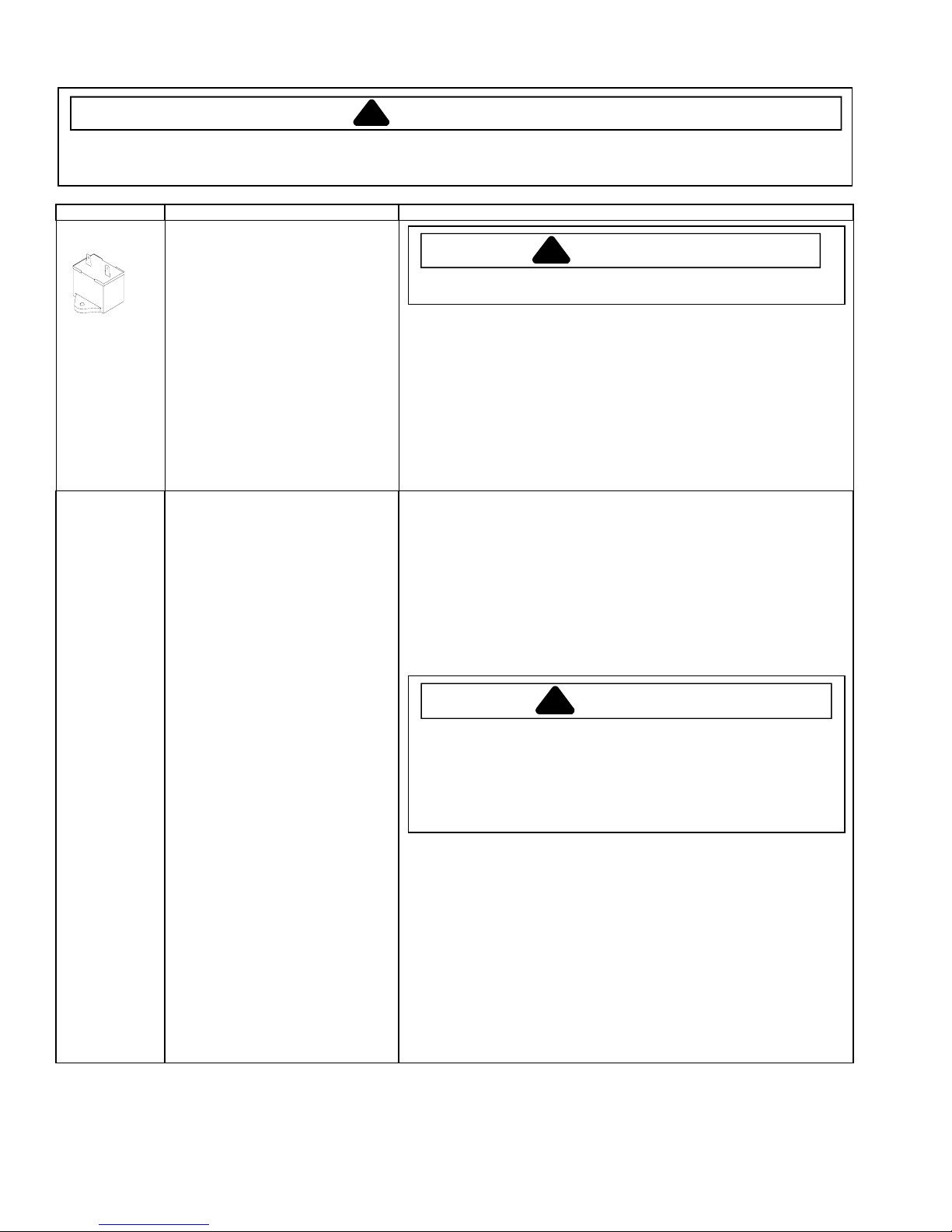
Capacitor
Condenser Condenser is a long folded tube
Run capacitor connects to relay terminal
3 and L side of line.
Some compressors do not require a run
capacitor; refer to the Technical Data
Sheet for the unit being serviced.
construction located in machine
compartment.
Condenser is on high pressure discharge
side of compressor. Condenser function
is to transfer heat absorbed by refrigerant
to ambient.
Higher pressure gas is circulated through
condenser where, as gas temperature is
reduced, It condenses into a high
pressure liquid state. Heat transfer takes
place because discharged gas is at a
higher temperature than air that is
passing over condenser. It is very
important that adequate air flow over
condenser is maintained.
Condenser is air cooled by condenser fan
motor. If efficiency of heat transfer from
condenser to surrounding air is impaired,
condensing temperature will increase.
High liquid temperature means liquid will
not remove as much heat during boiling
in evaporator as under normal conditions.
This would be indicated by high than
normal head pressures, long run time,
and high wattage. Remove any lint or
other accumulation, that would restrict
normal air movement through condenser.
From the condenser the refrigerant flows
into a post condenser loop which helps
control exterior condensation on flange,
center mullion, and around freezer door.
Refrigerant flows through the drier to the
capillary tube to the evaporator and back
to the compressor through suction line.
To avoid electrical shock which can cause severe personal injury or death,
discharge capacitor through a resistor before handling.
1. Disconnect power to refrigerator.
2. Disconnect the capacitor wires if present.
3. Discharge capacitor by shorting across terminals with a resistor for 1 minute.
4. Check resistance across capacitor terminals with ohmmeter set on “X1K”
scale.
• Good—needle swings to 0 ohms and slowly moves back to infinity.
• Open—needle does not move. Replace capacitor.
• Shorted—needle moves to zero and stays. Replace capacitor.
• High resistance leak—needle jumps toward 0 and then moves back to
constant high resistance (not infinity).
Leaks in condenser can usually be detected by using an electronic leak detector
or soap solution. Look for signs of compressor oil when checking for leaks that
may indicate the location of the leak. A certain amount of compressor oil is
circulated with refrigerant.
Leaks in post condenser loop are rare because loop is a one-piece steel tube.
“For small leaks”
1. Separate condenser from rest of refrigeration system and pressurize
condenser up to a maximum of 235 PSI with a refrigerant and dry nitrogen
combination.
2. Recheck for leaks.
To avoid severe personal injury or death from sudden eruption of high
pressures gases, observe the following:
Protect against a sudden eruption if high pressures are required for leak
checking.
Do not use high pressure compressed gases in refrigeration systems
without a reliable pressure regulator and pressure relief valve in the
lines.
WARNING
!
WARNING
!
16025860
6
©2005 Maytag Services

Component Testing
!
WARNING
To avoid risk of electrical shock, personal injury, or death, disconnect electrical power source to unit, unless test
procedures require power to be connected. Discharge capacitor through a resistor before attempting to service.
Ensure all ground wires are connected before certifying unit as repaired and/or operational.
Component Description Test Procedures
Overload / Relay
Temperature
control
Ice maker Optional on some models.
Condenser motor
Evaporator fan
motor
When voltage is connected and relay is
cool, current passes through relay to start
winding.
After a short time, current heats the
resistor in relay and resistance will raise
blocking current flow through relay.
Start winding remains in the circuit through
run capacitor.
Solid state relay plugs directly on
compressor start and run terminals. Relay
terminals 2 and 3 are connected within
relay. Run capacitor is connected to relay
terminal 3. L2 side of 120 VAC power is
connected to relay terminal 2.
Temperature control uses a capillary tube
to sense the temperature in the
compartment. Depending upon the
temperature it senses it will open or close
a single pole, single throw switch.
Temperature control controls run cycle
through defrost timer.
Altitude Adjustment
When altitude adjustment is required on a
G.E. control, turn altitude adjustment
screw 1/7 turn counter clockwise for each
1,000 feet increase in altitude up to 10,000
feet. One full turn equals 10,000 feet
maximum.
In most cases the need for altitude
adjustments can be avoided by simply
turning temperature control knob to colder
setting.
See “Ice Maker” section for service
information.
Condenser fan moves cooling air across
condenser coil and compressor body.
Condenser fan motor is in parallel circuit
with compressor.
Evaporator fan moves air across
evaporator coil and through the refrigerator
and freezer compartment.
1. Disconnect power to the refrigerator.
2. Remove relay cover and disconnect leads.
3. Check resistance across terminals 2 and 3 with an ohmmeter:
Normal = 3 to 12 ohms
Shorted = 0 ohms
Open = infinite ohms
Check for proper calibration with thermocouple capillary in air supply well by
recording cut-in and cut-out temperatures at middle setting. Refer to tech sheet
for model being serviced for expected temperatures.
Check control contacts are opening by disconnecting electrical leads to control
and turning control knob to coldest setting. Check for continuity across
terminals.
Altitude Counter in Feet
Feet Above
Sea Level
2,000
4,000
6,000
8,000
10,000
Check resistance across windings If open replace motor.
1. Disconnect power to unit.
2. Disconnect fan motor leads.
3. Check resistance from ground connection solder. Trace to motor frame must
not exceed .05 ohms.
4. Check for the proper operating voltage at the connector to motor with unit in
refrigeration mode and compressor operating.
Turn Screw
Clockwise (Angular
Degrees)
30
81
129
174
216
©2005 Maytag Services 16025860
7
Component Testing
!
WARNING
To avoid risk of electrical shock, personal injury, or death, disconnect electrical power source to unit, unless test
procedures require power to be connected. Discharge capacitor through a resistor before attempting to service.
Ensure all ground wires are connected before certifying unit as repaired and/or operational.
Component Description Test Procedures
Switch, upper
freezer light
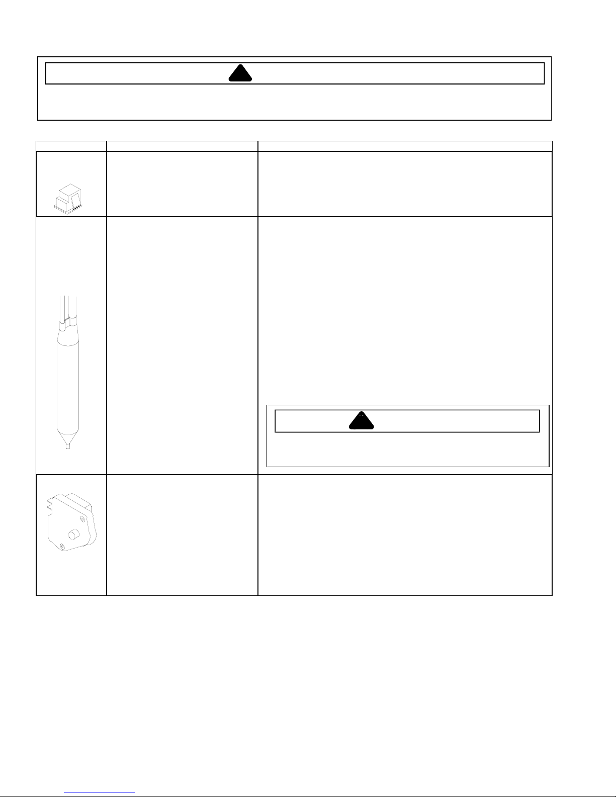
Drier
Defrost timer Timer motor operates only when fresh
Single pole, single throw switch
completes circuit for light when door is
open.
Drier is placed at post condenser loop
outlet and passes liquefied refrigerant to
capillary.
Desiccant (20) 8 x 12 4AXH - 7 M>S> Grams
food control is closed.
After specified amount of actual
operating time, inner cam in timer throws
the contacts from terminal 4, compressor
circuit, to terminal 2, defrost
thermostat/defrost heater circuit.
After specified defrost cycle time, timer
cam resets the circuitry through terminal
4 to compressor.
Check resistant across terminals.
Switch arm depressed
“NO” terminals Open
Switch arm up
“NO” terminals Closed
Drier must be changed every time the system is opened for testing or
compressor replacement.
NOTE: Drier used in R12 sealed system is not interchangeable with
drier used in R134a sealed system.
Before opening refrigeration system, recover HFC134a refrigerant for safe
disposal.
1. Cut drier out of system using the following procedure. Do not unbraze
drier since this will drive moisture into the system.
2. Score capillary tube close to drier and break. Reform inlet tube to drier
allowing enough space for large tube cutter.
3. Cut circumference of drier 1 ¼" below condenser inlet tube joint to
drier.
4. Remove drier.
5. Apply heat trap paste on post condenser tubes to protect grommets
from high heat.
6. Unbraze remaining part of drier. Remove drier from system.
7. Discard drier in safe place. Do not leave drier with customer. If
refrigerator is under warranty, old drier must accompany warranty
1. To check timer motor winding, check for continuity between terminals 1 and 3
2. Depending on rotating position of the cam, terminal 1 of timer is common to
3. With continuity between terminals 1 and 4, rotate timer knob clockwise until
4. Continuing to rotate time knob until a second click is heard should restore
claim.
WARNING
!
To avoid death or severe personal injury, cut drier at correct location.
Cutting drier at incorrect location will allow desiccant beads to scatter. If
spilled, completely clean area of beads.
of timer.
both terminal 2, the defrost mode, and terminal 4, the compressor mode.
There should never be continuity between terminals 2 and 4.
audible click is heard. When the click is heard, reading between terminals 1
and 4 should be infinite and there should be continuity between terminals 1
and 2.
circuit between terminals 1 and 4.
16025860
8
©2005 Maytag Services
Component Testing
•
•
!
WARNING
To avoid risk of electrical shock, personal injury, or death, disconnect electrical power source to unit, unless test
procedures require power to be connected. Discharge capacitor through a resistor before attempting to service.
Ensure all ground wires are connected before certifying unit as repaired and/or operational.
Component Description Test Procedures
Evaporator The low pressure in the evaporator
Evaporator heater
(defrost)
Thermostat
(defrost)
allows liquid refrigerant exiting the
capillary to expand into a gas.
Expansion cools evaporator coil
temperature to approximately -20°F
transferring heat from freezer section to
refrigerant.
Passing through suction line back to the
compressor, the refrigerant picks up
superheat (a relationship between
pressure and temperature that assures
complete vaporization of liquid
refrigerant) as the result of capillary tube
soldered to suction line.
Refrigerant gas is circulated through the
suction line by compressor, completing
refrigeration cycle.
Activated when defrost thermostat,
defrost timer, and freezer control
complete circuit through heater.
Thermostat is in a series circuit with
terminal 2 of defrost timer, and defrost
heater.
Controls the circuit from freezer
thermostat through defrost terminator to
defrost heater. Opens and breaks circuit
when thermostat senses preset high
temperature.
Test for leaks in evaporator with electronic leak detector or with soap solution.
Compressor oil is circulated with refrigerant; check for the presence of oil when
checking for leaks.
For minute leaks
1. Separate evaporator from rest of refrigeration system and pressurize
evaporator up to a maximum of 140 PSI with a refrigerant and dry nitrogen
combination.
2. Recheck for leaks.
WARNING
!
To avoid severe personal injury or death from sudden erruption of
high pressurres gases, observe the following:
Protect against a sudden eruption if high pressures are required
for leak checking.
Do not use high pressure compressed gases in refrigeration
systems without a reliable pressure regulator and pressure relief
valve in the lines.
Check resistance across heater.
To check defrost system :
1. Thermocouple defrost thermostat and plug refrigerator into wattmeter.
2. Turn into defrost mode. Wattmeter should read specified watts (according to
Technical Data Sheet).
3. When defrost thermostat reaches specified temperature ±5°F (see Technical
Data Sheet), thermostat should interrupt power to heater.
Test continuity across terminals.
With power off and evaporator coil below freezing, thermostat should show
continuity when checked with ohmmeter. See “Heater, evaporator (defrost)”
section for additional tests.
After defrost thermostat opens, thermostat remains open until end of defrost timer
cycles and refrigerator starts cooling again. Defrost thermostat senses a preset
low temperature and resets (closes).
©2005 Maytag Services 16025860
9


 Loading...