


Amana PTH Series
Maytag Amana PTH Series, Amana PTH Z Series, Amana PTH M Series, Amana PTC073A AA Series, Amana PTH R Series Service Instructions Manual
...
Service Instructions
Package Terminal
AirConditioners & Heat Pumps
This manual is to be used by qualified, professionally trained HVAC technicians only.
Goodman does not assume any responsibility for property damage or personal injury
due to improper service procedures or services performed by an unqualified person.
®
is a registered trademark of Maytag Corporation or its related companies and is used under license to Goodman Company, L.P., Houston, TX. All rights reserved.
© 2000 - 2009 Goodman Company, L.P.
RS4200003 Rev. 5
April 2009

INDEX
PRODUCT IDENTIFICATION ........................................................................................................ 4
SPECIFICATIONS ......................................................................................................................... 6
PROPER INSTALLATION ........................................................................................................... 17
WALL SLEEVE INSTALLATION ........................................................................................................................... 16
FRONT REMOVAL ................................................................................................................................................ 18
CHASSIS INSTALLATION .................................................................................................................................... 19
WIRING ................................................................................................................................................................. 19
OPERATING CONTROLS ..................................................................................................................................... 20
SCHEMATICS BASED ON 1 STAGE COOL,
2 STAGE HEAT MECHANICAL THERMOSTATS.................................................................................21
WIRELESS COMMUNICATIONS.............................................................................................................26
CONFIGURATION SETTINGS.............................................................................................................................. 32
MAINTENANCE........................................................................................................................... 33
OPERATIONS .............................................................................................................................. 36
SEQUENCE OF OPERATION ............................................................................................................................... 36
SERVICING ................................................................................................................................. 41
DIGITAL BOARD DIAGNOSTICS ........................................................................................................................ 49
DISASSEMBLY ........................................................................................................................... 59
SCHEMATICS ............................................................................................................................. 62
IMPORTANT INFORMATION
Pride and workmanship go into every product to provide our customers with quality products. It is possible, however, that
during its lifetime a product may require service. Products should be serviced only by a qualified service technician who
is familiar with the safety procedures required in the repair and who is equipped with the proper tools, parts, testing
instruments and the appropriate service manual. REVIEW ALL SERVICE INFORMATION IN THE APPROPRIATE
SERVICE MANUAL BEFORE BEGINNING REPAIRS.
IMPORTANT NOTICES FOR CONSUMERS AND SERVICERS
RECOGNIZE SAFETY SYMBOLS, WORDS AND LABELS
WARNING
WARNING
GOODMAN WILL NOT BE RESPONSIBLE FOR ANY INJURY OR PROPERTY DAMAGE ARISING FROM
IMPROPER SERVICE OR SERVICE PROCEDURES. IF YOU INSTALL OR PERFORM SERVICE ON THIS UNIT,
YOU ASSUME RESPONSIBILITY FOR ANY PERSONAL INJURY OR PROPERTY DAMAGE WHICH MAY
RESULT. MANY JURISDICTIONS REQUIRE A LICENSE TO INSTALL OR SERVICE HEATING AND AIR
CONDITIONING EQUIPMENT.
2

WARNING
THIS AIR CONDITIONER IS NOT MEANT TO PROVIDE
UNATTENDED COOLING OR LIFE SUPPORT FOR
PERSONS OR ANIMALS WHO ARE UNABLE TO
REACT TO THE FAILURE OF THIS PRODUCT.
THE FAILURE OF AN UNATTENDED AIR CONDITIONER MAY RESULT IN EXTREME HEAT IN THE CONDITIONED SPACE CAUSING OVERHEATING OR
DEATH OF PERSONS OR ANIMALS.
PRECAUTIONS MUST BE TAKEN TO WARN OF OR
GUARD AGAINST SUCH AN OCCURENCE.
WARNING
WARNING
INSTALLATION AND REPAIR OF THIS UNIT SHOULD BE PERFORMED ONLY BY INDIVIDUALS MEETING THE
REQUIREMENTS OF AN “ENTRY LEVEL TECHNICIAN” AS SPECIFIED BY THE AIR-CONDITIONING, HEATING
AND REFRIGERATION INSTITUTE (AHRI). ATTEMPTING TO INSTALL OR REPAIR THIS UNIT WITHOUT SUCH
BACKGROUND MAY RESULT IN PRODUCT DAMAGE, PERSONAL INJURY OR DEATH.
To locate an authorized servicer, please consult your telephone book or the dealer
from whom you purchased this product. For further assistance, please contact:
CONSUMER INFORMATION LINE -
AMANA® BRAND PRODUCTS TOLL FREE
1-877-254-4729 (U.S. only)
email us at: hac.consumer.affairs@amanahvac.com
fax us at: (931) 438- 4362
(Not a technical assistance line for dealers.)
Outside the U.S., call 1-931-433-6101.
(Not a technical assistance line for dealers.)
Your telephone company will bill you for the call.
3

PRODUCT IDENTIFICATION
n
PT C 07 3 B 35 A M
BASIC MODEL TYPE MAJOR/MINOR DESIGN REV.
PT = Stand ard PTAC
GM = Go odman PTAC
DRY = Dehumid PTAC
REFRIGERAT ION CY CLE
C = Cooler Only
H = Heat Pump
COOLING CAPACITY
07 = 7000 BTUH
09 = 9000 BTUH
10 = 10000 BTUH
12 = 12000 BTUH
15 = 15000 BTUH
RATE D V OLTAGE
2 = 115V 60Hz 1Ph
3 = 230/208V 60Hz 1Ph
4 = 265V 60Hz 1Ph
5 = 240/220V 50Hz 1Ph SPEACIAL FEATURE CO DE CONTROL FEATUR E
A = Standard Mod el ENGINEERING DESIGN REV
DESIGN STYLE B = Power Vent A = PAC-10
Old MAJ OR DESIGN SER IES C = Seacoast Protection B =
A = 3/ 8" Slab C ond. Coil Unit D = Conens ated Dis posal Pump C = PAC-20
B = Bent Con de nser Coil Unit F = H & B D = +EER, PAC-20
C = Sound Re duction G = H & J E = w/ " B" Design Series
D = 5/1 6" S lab Co nd . Coil Un it H = Hydronic F = +EE R w/ "B" Des i gn Series
J = Power Door G = M60
K = D & B H = +EER, M60 (o ld)
L = D & J H = M61S , Rech i
HEATE R SIZE M = STC J = PAC -20, LCDI
0 0 = no el ec t r ic heat N = C & J K = M60, LCDI
15 = 1.5 kW P = C & H & B L = +EER, M60, LCDI
2 5 = 2. 5 kW R = Added Drain V alve (PTC) M = M61
35 = 3.5 kw (230/2 08V) T = Aux Transformer N = +EER, M61
= 3.7kW (265 V) X = H ard Wire d Only P = M6 1S
5 0 = 5.0 kW Y = 230V F use Holder Kit Q = Mechanical Contr ol
U = open R = M61, Rech i
V = open S = op e n
W = open T = M61, 7-Button
Z = C & D U = M61, Alt Pana sonic
V = open
W = M61
Out of Pro duction
X = ope
Y = M61, 7-Button, & DT01A
Z = M61, DT01A , Rechi
BM
Wireless Ready
DT 01A
4

PRODUCT IDENTIFICATION
NT E 12 A 35 A 3 A
Package
T e r mina l Units
Model Type Voltage
E - Cooler 3 = 230/208-1-60
P - Heat Pump 4 = 265-1-60
Nominal Cooling Capacity
07: 7,000 Btuh A = Standard Model
09: 9,000 Btuh C = Seacoast Model
12 : 1 2 ,0 00 Btuh
15 : 1 5 ,0 00 Btuh
Electric Heat
25 = 2.5 kW
Option Code
Engineering
Revision
Design Series
5

SPECIFICATIONS
PTC073A**AA PTC074A**AA PTC093A**AA PTC094A**AA PTC123A**AA PTC124A**AA PTC153A**AA PTC154A**AA
1&3
Voltage
Capacity (BUTH)
Amps
Watts
EER
UNIT WITHOUT
ELECTRIC HEATER
Minimum Circuit Ampacity
CFM
HIGH 220/215 220 220/215 220 290/270 290 325/315 325
HIGH 235/230 235 235/230 235 310/290 310 345/335 345
Dehumidification
(pints/hr)
Net Weight
Shipping Weight (approx.
lbs.)
2&4
LOW 175/155 175 175/155 175 220/190 220 250/220 250
LOW 185/165 185 185/165 185 235/205 235 265/235 265
230/208 265 230/208 265 230/208 265 230/208 265
7,500/7,400 7,500 9,000/8,800 9,000 12,200/12,000 12,200 14,200/14,000 14,200
2.5/2.6 2.0 3.5/3.8 3.0 4.6/5.0 3.7 7.4/7.9 6.5
625/610 625 810/790 810 1,145/1,125 1,145 1,510/1,490 1,510
11.6 11.6 11.1 11.1 10.8 10.8 9.4 9.4
4.0 3.3 4.8 4.1 7.3 5.7 8.4 7.7
35 35 35 35 45 45 50 50
1.9 1.9 2.7 2.7 3.8 3.8 4.4 4.4
110 110 120 120 130 130 140 140
130 130 140 140 150 150 160 160
COOLING DATA (COOLING with ELECTRIC HEAT)
Cool, Wet Coil
Dry Coil
Ventilated Air
1&3
Voltage
Capacity (BUTH)
Amps
Watts
EER
UNIT WITHOUT
ELECTRIC HEATER
Minimum Circuit Am pacity
CFM
HIGH 220/215 220 220/215 220 290/270 290 325/315 325
LOW 175/155 175 175/155 175 220/190 220 250/220 250
HIGH 235/230 235 235/230 235 310/290 310 345/335 345
LOW 185/165 185 185/165 185 235/205 235 265/235 265
Dehumidification
(pints/hr)
Net Weight
Shipping Weight (approx.
lbs.)
COOLING DATA (HEAT PUMP)
PTH073A**AA PTH074A**AA PTH093A**AA PTH094A**AA PTH123A**AA PTH124A**AA PTH153A**AA PTH154A**AA
230/208 265 230/208 265 230/208 265 230/208 265
7,400/7,200 7,400 9,000/8,800 9,000 12,000/11,600 12,000 14,000/13,800 14,000
2.5/2.6 2.0 3.5/3.8 3.0 4.6/5.0 3.7 7.4/7.9 6.5
625/610 625 810/790 810 1,145/1,125 1,145 1,490/1,470 1490
11.5 11.5 11.1 11.1 10.6 10.6 9.4 9.4
2&4
4.0 3.3 4.8 4.1 7.3 5.7 8.4 7.7
Cool, Wet Coil
Dry Coil
Ventilated Air
35 35 35 35 45 45 50 50
1.9 1.9 2.7 2.7 3.8 3.8 4.4 4.4
110 110 120 120 130 130 140 140
130 130 140 140 150 150 160 160
NOTES:
1. All 265V models must use Amana® brand’s subbase (PTSB4**C) or Amana® brand’s hard wire kit (PTPWHWK4).
2. Minimum branch circuit ampacity rating conform to the National Electric Code. However, local codes should apply .
3. Minimum voltage on 230/208 volt models is 197 volts; maximum is 253 volts. Minimum voltage on 265 volt models is 238.5 volts; maximum is 291.5
volts.
4. Overcurrent protection for all units without electric heaters is 15 amps. Overcurrent protection on 265 volt models must be cartridge-style time
delay fuses (included and factory installed on Amana® brand chassis).
5. Heating capacity and efficiency are based on unit operation without condensate pump. Unit automatically switches to electric heat at 25°F
outdoor coil temperature.
6. Tot al watts for 15,000 Btuh models; subtract 30 watts for PT12*A**AA and 70 watts for PT07/09*A**AA.
7. Please specify 2-digit heater kW size to complete model number.
8. Total amp s for 12,000 and 15,000 Btuh models; subtract 0.2 amps for PT07/09*A*AA.
6
EER - Energy Efficiency Ratio per The Air-Conditioning,
Heating, and Refrigeration Institute (AHRI) Test
Procedures and Canadian Standards Association
(CSA) Test Procedures
COP - Coefficient of Performance per AHRI T est
Procedures
SPECIFICATIONS
Heating Capacity
Reverse Cycle
CFM (Dry)
Ra ting
Point
1&7
Amp s
Watts
5
BTUH
5
COP
Out doo r A mbi entºFHeating BTUH
62 8,500/8,400 8,500 10,6 00/10,500 10,600 13,200/13,000 16,500/16,200 16,500
57 7,900/7,800 7,900 10,000/9,900 10,000 12,400/12,200 15,500/15,200 15,500
52 7,200/7,100 7,200 9,300/9,200 9,300 11,600/11,400 14,400/14,100 14,400
47 6,500/6,400 6,500 8,400/8,300 8,400 10,800/10,600 13,400/13,100 13,400
(COP) 3.3/3.3 3.3 32./3.2 3.2 3.1/3.1 2.9/2.9 2.9
452 5,800/5,700 5,800 7,600/7,500 7,600 10,000/9,800 12,300/12,100 12,300
37 5,200/5,100 5,200 6,800/6,700 6,800 9,200/9,000 11,400/11,200 11,400
32 4,600/4,500 4,600 6,000/5,900 6,000 8,400/8,200 10,300/10,100 10,300
Out doo r A mbi ent
ºF
62 600/650 660 860 860 1,120/1,100 1,500/1,470 1,500
57 635/625 635 830 830 1,090/1,070 1,450/1,420 1,450
52 600/590 600 800 800 1,050/1,030 1,400/1,380 1,400
47 575/565 575 770 770 1,020/1,000 1,350/1,320 1,350
42 550/540 550 840 740 990/970 1,290/1,265 1,290
37 525/515 525 710 710 950/930 1,225/1,200 1,225
32 500/490 500 680 680 920/900 1,170/1,140 1,170
PTH073A**AA PTH074A**AA PTH094A**AA PTH123A**AA PTH124A**AA PTH153**AA PTH154A**AA
2.6/3.0 2.2 2.6 4.5/5.1 3.9 5.0/5.6 4.1
575/565 575 770 1,020/1,000 1,020 1,350/1,320 1,350
6,800/6,700 6,800 8,500 11,200/11,100 11,200 13,400/13,100 13,400
3.3 3.3 3.2 3.1 3.1 2.9 2.9
235/230 235 234 310/290 310 345/335 345
Note 5
Watts Watts Watts Watts Watts Watts Watts
HEATING PERFORMANCE - REVERSE CYCLE
Heating BTUH
Note 5
Heating BTUH
Note 5
Heating B TUH
Note 5
Heating BTUH
Note 5
H eating BT UH
No te 5
Heating BTUH
Note 5
COOLIN G DATA (COOLIN G with ELEC TRIC HEAT)
PTC073A**AB
1&3
Voltage
Capacity (BUTH)
Amps
Watts
EER
UNIT WITHOUT
ELEC TR IC HEATER
Min imum Circuit Ampacity
CFM
HI GH 245/240 245 245/ 240 245 325/315 325 325/315 325
L OW 220/205 220 220/205 220 250 /229 250 250/220 250
HI GH 265/260 265 265/ 260 265 345/335 345 345/335 345
L OW 230/215 230 230/215 230 265 /235 265 265/235 265
FAN ONLY* 65* 65* 65* 65* 70* 70* 70* 70*
COM PRESSOR & FAN* 65* 65* 65* 65* 70* 70* 70* 70*
Deh umidification
(pints/h r)
Net Weight
Shipping Weight (approx.
lbs.)
PTC073A**AC
230/208 265 230/ 208 265 230/208 265 230/208 265
7,100/7,000 7,100 9,100/8,900 9,100 12,000/11,900 12,000 14,2 00/14,000 14,200
2.8/3.0 2 3.7/3.8 3 4.6/5.0 4.3 6.3/6.9 5.9
610/600 610 805/ 785 805 1,120 /1,110 1,130 1,5 45/1,520 1,525
11.6 11.6 11.3 11.3 10. 7 10.7 9.2 9.3
2&4
4.0 3. 6 5.1 4.4 6.4 5.7 8.4 7.4
1.6 1. 6 2.6 2.6 3.5 3.5 4.4 4.4
90 90 95 95 105 105 110 110
105 105 110 110 120 120 125 125
NOTES:
1. All 265V models must use Amana® brand’s subbase (PTSB4**C) or Amana® brand’s hard wire kit (PTPWHWK4).
2. Minimum branch circuit ampacity rating conform to the National Electric Code. However, local codes should apply .
3. Minimum voltage on 230/208 volt models is 197 volts; maximum is 253 volts. Minimum voltage on 265 volt models is 238.5 volts; maximum is 291.5
volts.
4. Overcurrent protection for all units without electric heaters is 15 amps. Overcurrent protection on 265 volt models must be cartridge-style time
delay fuses (included and factory installed on Amana® brand chassis).
5. Heating capacity and efficiency are based on unit operation without condensate pump. Unit automatically switches to electric heat at 25°F
outdoor coil temperature.
6. Tot al watts for 15,000 Btuh models; subtract 30 watts for PT12*A**AA and 70 watts for PT07/09*A**AA.
7. Please specify 2-digit heater kW size to complete model number.
8. Total amp s for 12,000 and 15,000 Btuh models; subtract 0.2 amps for PT07/09*A*AA.
PTC074A**AB
PTC074A**AC
PTC093A**AB
PTC093A**AC
PTC094A** AB
PTC094A** AC
Cool, Wet Coil
Dr y Co il
Ventilated Air
PTC123A**AB
PTC123A**AC
PTC124A**AB
PTC124A**AC
EER - Energy Efficiency Ratio per The Air-Conditioning,
COP - Coefficient of Performance per AHRI T est
PTC153A**AB
PTC153A**AC
Heating, and Refrigeration Institute (AHRI) Test
Procedures and Canadian Standards Association
(CSA) Test Procedures
Procedures
PTC154A**AB
PTC154A**AC
7

SPECIFICATIONS
y
Outd
Outd
Heating Capacity
Reverse Cycle
Amp s
Watts
5
BTUH
5
COP
CFM (Dry )
Ambient
Ra ting
Point
(COP) 3.3/3. 3 3.3 32./3.2 3.2 3.1/3 .1 2. 9/2.9 2.9 * * *
452 5,700/5,500 5,700 7,300/7,200 7,300 10,000/ 9, 800 10,000 12, 300/12,200 12,300
Ambient
1& 7
PTH 073A* *AB
PTH 073A* *AC
PT H074A **AB
PT H074A **AC
2.6/3.0 2.2 3.2/3.6 2.6 4.5/5 .1 3.9 5.7/6.3 5.4
570/550 570 740/73 0 740 1,020/1 ,000 1,020 1,390/1,380 1,390
6,400/6,200 6,400 8,100/8,000 8,100 10,800/10,600 10,800 13,300/13,200 1 3,300
3.3 3.3 3.2 3.2 3.1 3.1 2.8 2.8
235/230 235 235/23 0 230 310/290 310 345/335 345
oor
º
Heatin g BTUH
No te 5
Heating BTUH
62 8,400/8,200 8,400 10,300/10 ,200 10,300 13,200/13,000 13,200 16,400/16,300 16,400
57 7,800/7,600 7,800 9,700/9,600 9,700 12,400/1 2,200 12,400 15,400/15,300 1 5,400
52 7,100/6,900 7,100 9,000/8,900 9,000 11,600/1 1,400 11,600 14,300/14,200 1 4,300
47 6,400/6,200 6,400 8,100/8,000 8,100 10,800/1 0,600 10,800 13,300/13,200 1 3,300
37 5,100/4,900 5,100 6,500/6,400 6,500 9,200/9,000 9200 11,300/11,200 11,300
32 4,500/4,300 4,500 5,700/5,600 5,700 8,400/8,200 8400 10,200/10,100 10,200
oor
Watts Wat ts Wa tts W atts Watts W atts W atts Watts
ºF
62 645/625 645 835/825 835 1,151/1,095 1,115 1,540/1,530 1,540
57 630/610 630 805/795 805 1,085/1,065 1,085 1,500/1,490 1,500
52 595/575 595 780/770 780 1,055/1,035 1,055 1,450/1,440 1,450
47 570/550 570 740/730 740 1,020/1,000 1,020 1,390/1,380 1,390
42 540/520 540 710/700 710 985/965 985 1,335/1,325 1,335
37 515/505 515 675/665 675 945/925 945 1,250/1,240 1,250
32 495/485 495 630/620 630 915/895 915 1,170/1,160 1,170
27 460/450 460 590/580 590 885/865 885 1,110/1,090 1,100
HEAT IN G PE RFORM ANC E - REV ERSE CYC L E
Note 5
PTH093A**AB
PTH093A**AC
Heating BTU H
Note 5
PTH094A**AB
PTH094A**AC
Heating BTU H
Note 5
PTH123A**AB
PTH123A**AC
Heating BTUH
Note 5
PTH124A**AB
PTH124A**AC
Hea ting BTUH
Note 5
PTH153A**AB
PTH153A**AC
Heat in g BTUH
Note 5
PTH154A* *A B
PTH154A* *A C
Heatin g BTUH
Note 5
COOLING DATA (HEAT PUMP)
PTH073A**AB
1&3
Voltage
Capacity (BUTH)
Amps
Watts
EER
UNIT WITHOUT
ELECTRIC HEATER
Minimum Circuit Ampacit
CFM
FAN ONLY* 65* 65* 65* 65* 70* 70* 70* 70*
COMPRESSOR & FAN* 65* 65* 65* 65* 70* 70* 70* 70*
Dehumidification
(pints/hr)
Net Weight
Shipping Weight
(approx. lbs.)
PTH073A**AC
230/208 265 230/208 265 230/208 265 230/208 265
7,100/7,000 7,100 9,000/8,800 9,000 12,000/11,800 12,000 14,000/13,800 14,000
2.8/3.0 2.3 3.5/3.8 3.0 4.6/5.0 4.3 6.3/6.9 5.9
651/610 615 805/785 805 1,120/1,110 1,120 1,505/1,485 1,505
11.5 11.5 11.2 11.2 10.7 10.7 9.3 9.3
2&4
HIGH 245/240 245 245/240 245 325/315 325 325/315 325
LOW 220/205 220 220/205 220 250/229 250 250/220 250
HIGH 265/260 265 265/260 265 345/335 345 345/335 345
LOW 230/215 230 230/215 230 265/235 265 265/235 265
4.0 3.6 5.1 4.4 6.4 5.7 8.4 7.4
1.6 1.6 2.6 2.6 3.5 3.5 4.4 4.4
95 90 100 100 110 110 115 115
110 110 115 115 125 125 130 130
NOTES:
1. All 265V models must use Amana® brand’s subbase (PTSB4**C) or an Amana® brand hard wire kit (PTPWHWK4).
2. Minimum branch circuit ampacity ratings conform to the National Electric Code. However, local codes should apply .
3. Minimum voltage on 230/208 volt models is 197 volts; maximum is 253 volts. Minimum voltage on 265 volt models is 238.5 volts; maximum is 291.5 volts.
4. Overcurrent protection for all units without electric heaters is 15 amps. Overcurrent protection on 265 volt models must be cartridge-style time delay fuses (included
and factory installed on Amana® brand all 265 volt chassis).
5. Heating capacity and efficiency are based on unit operation without condensate pump. Unit automatically switches to electric heat at approximately 24°F outdoor ambient.
6. Total watt s for 12,000 and 15,000 Btuh models. Subtract 70 watts for PT07/09*B*AE.
7. Please specify 2-digit heater kW size to complete model number.
9. Refrigerant used in all systems is R-22.
8. Total amp s for 12,000 and 15,000 Btuh models; subtract 0.2 amps for PT07/09*B*AE.
10. All units meet or exceed ASHRAE 90.1 standards..
PTH74A**AB
PTH074A**AC
PTH093A**AB
PTH093A**AC
PTH094A**AB
PTH094A**AC
Cool, Wet Coil
Dry Coil
Ventilated Air
PTH123A**AB
PTH123A**AC
PTH124A**AB
PTH124A**AC
PTH153A**AB
PTH153A**AC
8
PTH154A**AB
PTH154A**AC

SPECIFICATIONS
COO LING DATA (COOLING with ELECTRIC HEAT )
PTC073B***
E - Y
1&3
Voltage
Capacity (BUTH) 7,100/6,900 7,100 9,100/8,900 9,100 12,000/11,900 12,000 14,000/13,900 14,000
Amps 2.8/3.0 2 3.7/3.8 3 4.6/5.0 4.3 6.3/6.9 5.9
Watts 610/595 610 790/775 790 1,110/1,100 1,130 1,470/1,450 1,470
EER 11.6 11.6 11.5 11.5 10.8 10.8 9.5 9.5
UNIT WITHOUT
ELEC TR IC HEATER
Min i mu m C ircuit Ampa city
CFM
HIGH 245/240 245 245/240 245 325/315 325 325/315 325
LOW 220/205 220 220/205 220 250/229 250 250/220 250
HIGH 265/260 265 265/260 265 345/335 345 345/335 345
LOW 230/215 230 230/215 230 265/235 265 265/235 265
COMPR ESSOR & FAN* 65 65 65 65 70 70 70 70
Deh umidific ation
(pints/hr)
Net Weight 90 90 95 95 105 105 110 110
Shipping Weight
(approx. lbs.)
*Approximately 95 CFM with optional power vent kit. Actual vent CFM performance will vary due to application and installation conditions.
230/208 265 230/208 265 230/208 265 230/208 265
2&4
4.0 3.6 5.1 4.4 6.4 5.7 8.8 7.7
1.6 1.6 2.6 2.6 3 .5 3.5 4.4 4.4
105 105 110 110 120 120 125 125
PTC 074B* **
E - Y
PTC093B***
E - Y
PTC094B***
E - Y
Cool, Wet Coil
Ventilated Air
Dr y Co il
PTC123B***
E - Y
PTC124B***
E - Y
PTC 153B* **
E - Y
PTC154B***
E - Y
COO LING DATA (COOLING with ELECTRIC HEAT)
PTH073B***
E - Y
1&3
Voltage
Capacity (BUTH) 7,000/6,800 7,000 9,100/8,900 9,100 12,000/11,800 12 ,000 14,000/13,900 14,000
Amps 2.8/3.0 2 3.5/3.8 3 4.6/5.0 4.3 6.3/6.9 5.9
Watts 605/585 605 790/775 790 1,110/1,090 1,110 1,505/1,495 1,505
EER 11.6 11.6 11.5 11.5 10.8 10.8 9.3 9.3
UNIT WITHOUT
ELEC TR IC HEATER
Min i mu m C i r cuit Am pa city
CFM
HIGH 245/240 245 245/240 245 325/315 325 325/315 325
LOW 220/205 220 220/205 220 250/229 250 250/220 250
HIGH 265/260 265 265/260 265 345/335 345 345/335 345
LOW 230/215 230 230/215 230 265/235 265 265/235 265
COMPR ESSOR & FAN* 65 65 65 65 70 70 70 70
Deh umidific ation
(pints/hr)
Net Weight 95 95 100 100 110 110 115 115
Shipping Weight
(approx. lbs.)
230/208 265 230/208 265 230/208 265 230/208 265
2&4
4.0 3.6 5.1 4.4 6.4 5.7 8.8 7.7
1.6 1.6 2.6 2.6 3.5 3.5 4.4 4.4
110 110 115 115 125 125 130 130
PTH 074B* **
E - Y
PTH093B***
E - Y
PTH094B***
E - Y
Cool, Wet Coil
Ventilated Air
Dr y Co il
PTH123B***
E - Y
PTH124B***
E - Y
PTH 153B* **
E - Y
PTH154B***
E - Y
NOTES:
1. All 265V models must use Amana® brand’s subbase (PTSB4**E) or an Amana® brand hard wire kit (PTPWHWK4).
2. Minimum branch circuit ampacity ratings conform to the National Electric Code. However, local codes should apply .
3. Minimum voltage on 230/208 volt models is 197 volts; maximum is 253 volts. Minimum voltage on 265 volt models is 238.5 volts; maximum is 291.5 volts.
4. Overcurrent protection for all units without electric heaters is 15 amps. Overcurrent protection on 265 volt models must be cartridge-style time delay fuses (included
and factory installed on Amana® brand all 265 volt chassis).
5. Heating capacity and efficiency are based on unit operation without condensate pump. Unit automatically switches to electric heat at approximately 24°F outdoor ambient.
6. Total watt s for 12,000 and 15,000 Btuh models. Subtract 70 watts for PT07/09*B*AE.
7. Please specify 2-digit heater kW size to complete model number.
9. Refrigerant used in all systems is R-22.
8. Total amp s for 12,000 and 15,000 Btuh models; subtract 0.2 amps for PT07/09*B*AE.
10. All units meet or exceed ASHRAE 90.1 standards..
9

SPECIFICATIONS
HEAT IN G PERF ORMANCE - R EVERSE CYC LE
Heating Capacity
Reverse Cycle
12
Amps
Watts
5
BTUH
5
COP
CFM (Dry )
Outdoor
Ambient
ºF
62 7,200/7,000 7,200 9,800/9,600 9,800 13,000/12,800 13,000 15,800/15,700 15,800
57 6,900/6,700 6,900 9,300/9,100 9,300 12,300/12,100 12,300 15,000/14,900 15,000
52 6,500/6,300 6,500 8,700/8,500 8,700 11,600/11,400 11,600 14,200/14,100 14,200
47 6,200/6,000 6,200 8200/8,000 8,200 10,800/10,600 10,800 13,300/13,200 13,300
Ra ting
Point
(COP) 3.3/3.3 3.3 3.2/3.2 3.2 3.1/3.1 3.1 2.9/2.9 2.9
452 5,900/5,700 5,900 7,700/7,500 7,700 10,100/9,900 10,100 12,500/12,400 12,500
37 5,600/5,400 5,500 7,200/7,00 7,200 9,400/9,200 9,400 11,700/11,600 11,700
32 5,300/5,100 5,200 6,700/6,500 6,700 7,900/7 ,700 7,900 10,000/9,900 10,000
Outdoor
Ambient
ºF
62 580/560 580 810/790 810 1,120/1,100 1,120 1,465/1,455 1,465
57 575/555 575 800/780 800 1,090/1,075 1,090 1,440/1,430 1,440
52 555/535 555 775/755 775 1,060/1,045 1,060 1,405/1,395 1,405
47 550/530 550 750/730 750 1,020/1,005 1,020 1,340/1,330 1,340
42 540/525 560 730/710 730 985/9 70 985 1,325/1,315 1, 325
37 530/515 545 705/685 705 950/9 35 950 1,285/1,275 1, 285
32 515/500 535 690/670 690 900/8 85 900 1,240/1,230 1, 190
PTH073B***
1& 7
E - Y
6,200/6,00 6200 8,200/8,000 8200 10,800/1 0,600 10800 13,300/13,200 13,300
2.6/3.0 2.2 3.2/3.6 2.6 4.5/5.1 3.9 5.7/6.3 5.4
550/530 550 750/730 750 1020/1,000 1020 1,340/1,330 1,340
3.3 3.3 3.2 3.2 3.1 3.1 2.9 2.9
235/230 235 235/230 230 310/290 310 345/335 345
Heatin g BT UH
No te 5
Watts Watts Watts Watts Watts W atts Watts Watts
PTH074B***
E - Y
Heating BTUH
Note 5
PTH093B***
E - Y
Heating BTUH
Note 5
PTH094B***
E - Y
Heating BTUH
Note 5
PTH123B***
E - Y
Heating BT UH
Note 5
PTH124B***
E - Y
Hea ting BT UH
Note 5
PTH153B***
E - Y
Heatin g BT UH
Note 5
PTH154B***
E - Y
Heatin g BT UH
Note 5
HEAT PER FORMANCE (EL ECT RIC HEAT) EL ECT RIC DATA
(A LL BTUH SI ZES, ALL MODEL S)
Voltage
230/208
230/208
230/208
265
265
265
* PTH/PTC09*B50*G/K have the same airflow as a PTC/PT H12*B***G (not available on 7,000 BTU/h models).
NOTES:
1. All 265V models must use Amana® brand’s subbase (PTSB4**E) or an Amana® brand hard wire kit (PTPWHWK4).
2. Minimum branch circuit ampacity ratings conform to the National Electric Code. However, local codes should apply .
3. Minimum voltage on 230/208 volt models is 197 volts; maximum is 253 volts. Minimum voltage on 265 volt models is 238.5 volts; maximum is 291.5 volts.
4. Overcurrent protection for all units without electric heaters is 15 amps. Overcurrent protection on 265 volt models must be cartridge-style time delay fuses (included
and factory installed on Amana® brand all 265 volt chassis).
5. Heating capacity and efficiency are based on unit operation without condensate pump. Unit automatically switches to electric heat at approximately 24°F outdoor ambient.
6. Total watt s for 12,000 and 15,000 Btuh models. Subtract 70 watts for PT07/09*B*AE.
7. Please specify 2-digit heater kW size to complete model number.
9. Refrigerant used in all systems is R-22.
8. Total amp s for 12,000 and 15,000 Btuh models; subtract 0.2 amps for PT07/09*B*AE.
10. All units meet or exceed ASHRAE 90.1 standards.
11. Some units less than 250 volts have a Leak Current Detector Interrupter (LCDI) power cord and meeat UL 484 standards.
12. Refer to electric heat performance data for total MCA and recommended overcurrent protection. Amp s and Watts notation refers to compressor only .
Electric Heater S ize
(kW)
2 .5/ 2.0 1 8 ,500 6,800 - -- 2,650/2, 140 11.6/10. 5 14.5 15 6 - 15 P
3 .5/2.9 1 12,000 9,900 --- 3, 650/3,040 15.9/14.5 19.9 20 6 - 20 P
5. 0/4.1 1* 17,100 14,000 --- 5,150/ 4,240 22.4/20.4 28.1 30 6 -30 P
2.5 1 --- --- 8,500 2,650 10. 1 12.7 15 7 - 20 P
3.7 1 --- --- 12,600 3,850 14.7 18.3 20 7 - 20 P
5.0 1* --- --- 17 ,100 5,150 19.6 24. 5 25 7 - 30 P
Number
of
Stages
Nomina l Heating
(BTUH)
230V 208V 265V
Total
Watts
Total
Amps
Minimum
Ampacity
Overcurrent
1
Protection
Power
5
Co rd
1
10

SPECIFICATIONS
COOLING DATA (ELECTRIC HEAT)
NTE07A**A3A NTE07A**A4A NTE09A**A3A NTE09A**A4A NTE12A**A3A NTE12A**A4A NTE15A**A3A NTE15A**A4A
1&3
Voltage
Capacity (BUTH)
Amps
Watts
EER
UNIT WITHOUT
ELECTRIC HEATER
Minimum Circuit Ampacity
CFM
HIGH 245/240 245 245/240 245 325/315 325 325/315 325
LOW 220/205 220 220/205 220 250/229 250 250/220 250
HIGH 265/260 265 265/260 265 345/335 345 345/335 345
LOW 230/215 230 230/215 230 265/235 265 265/235 265
FAN ONLY* 65* 65* 65* 65* 70* 70* 70* 70*
COMPRESSOR & FAN* 65* 65* 65* 65* 70* 70* 70* 70*
Dehumidification
(pints/hr)
Net Weight
Shipping Weight (approx.
lbs.)
*Approximately 95 CFM with optional power vent kit. Actual vent CFM performance will vary due to application and installation conditions.
230/208 265 230/208 265 230/208 265 230/208 265
7,100/6,900 7,100 9,100/8,900 9,100 11,900/11,700 11,900 13,700/13,500 13,700
2.8/3.0 2.3 3.7/3.8 3.0 4.9/5.3 4.3 6.3/6.9 5.9
655/640 655 830/810 830 1,165/1,145 1,165 1,540/1,515 1,540
10.8 10.8 11 11 10.2 10.2 8.9 8.9
2&4
4.0 3.6 5.1 4.4 6.4 5.7 8.4 7.4
Cool, Wet Coil
Dry Coil
Ventilated Air
1.6 1.6 2.6 2.6 3.5 3.5 4.4 4.4
90 90 95 95 105 105 110 110
105 105 110 110 120 120 125 125
COOLING DATA (HEAT PUMP)
NTP07A**A3A NTP07A**A4A NTP09A**A3A NTP09A**A4A NTP12A**A3A NTP12A**A4A NTP15A**A3A NTP15A**A4A
1&3
Voltage
Capacity (BUTH)
Amps
Watts
EER
UNIT WITHOUT
ELECTRIC HEATER
Minimum Circuit Ampacity
CFM
HIGH 245/240 245 245/240 245 325/315 325 325/315 325
LOW 220/205 220 220/205 220 250/229 250 250/220 250
HIGH 265/260 265 265/260 265 345/335 345 345/335 345
LOW 230/215 230 230/215 230 265/235 265 265/235 265
FAN ONLY* 65* 65* 65* 65* 70* 70* 70* 70*
COMPRESSOR & FAN* 65* 65* 65* 65* 70* 70* 70* 70*
Dehumidification
(pints/hr)
Net Weight
Shipping Weight (approx.
lbs.)
230/208 265 230/208 265 230/208 265 230/208 265
7,000/6,800 7,000 8,900/8,700 8,900 11,600/11,400 11,600 13,700/13,500 13,700
2.8/3.0 2.3 3.5/3.8 3.0 4.6/5.0 4.3 6.3/6.9 5.9
655/635 655 825/805 825 1,160/1,140 1,160 1,540/1,515 1,540
10.7 10.7 10.8 10.8 10.0 11.0 8.9 8.9
2&4
4.0 3.6 5.1 4.4 6.4 5.7 8.4 7.4
Cool, Wet Coil
Dry Coil
Ventilated Air
1.6 1.6 2.6 2.6 3.5 3.5 4.4 4.4
95 95 100 100 110 110 115 115
110 110 115 115 125 125 130 130
NOTES:
1. All 265V models must use Amana® brand’s subbase (PTSB4**D) or an Amana® brand hard wire kit (PTPWHWK4).
2. Minimum branch circuit ampacity ratings conform to the National Electric Code. However, local codes should apply .
3. Minimum voltage on 230/208 volt models is 197 volts; maximum is 253 volts. Minimum voltage on 265 volt models is 238.5 volts; maximum is 291.5 volts.
4. Overcurrent protection for all units without electric heaters is 15 amps. Overcurrent protection on 265 volt models must be cartridge-style time delay fuses (included
and factory installed on Amana® brand all 265 volt chassis).
5. Heating capacity and efficiency are based on unit operation without condensate pump. Unit automatically switches to electric heat at approximately 24°F outdoor ambient.
6. Total watt s for 12,000 and 15,000 Btuh models. Subtract 70 watts for PT07/09*B*AE.
7. Please specify 2-digit heater kW size to complete model number.
9. Refrigerant used in all systems is R-22.
8. Total amp s for 12,000 and 15,000 Btuh models; subtract 0.2 amps for PT07/09*B*AE.
10. All units meet or exceed ASHRAE 90.1 standards..
11

SPECIFICATIONS
COOLING DATA (COOLING with ELECTRIC HEAT)
PTC****A*
1, 7 , 9, 10, 12
Model
1, 3, 11
Vol tage
Capacity (BUTH)
Am ps
Watts
EER
PTC
073D** AR
230 / 208 23 0 / 208 230 / 2 08 2 30 / 2 08 230 / 208 230 / 208
7,200/7,00 0 9,100 / 8,900 11,700 / 11,60 0 12,000 / 11,800 13,3 00 / 13,200 14,000/13,8 00
3.5/3.5 4.4/4.4 4.8/5.2 5.4/5.4
625/600 7 9 0 / 775 1,070,/,1,040 1,120 ,/,1,100
11.5/11.7 11.5 11.0/11.2 10.7 10.5/10.7 9.7
PTC
093D**AR
PTC
123C** AM
PTC
123D**AR
PTC
133D** AR
5.9/6.4
1265/1235
UNIT WITHOUT
ELECTRIC HEATE R
Minimum Circui t Ampa city
CFM
2, 4, 12
4.2 5.4 6.4 6.6 7.8 8.2
Cool, Wet Coil
HIGH 220/215 220/215 220/215 310/300 310/300 310/300
LOW 195/190 195/190 195/190 240/230 240/230 240/230
Dry Coil
HIGH 240/235 240/235 240/235 335/325 335/325 335/325
LOW 210/205 210/205 210/205 260/250 260/250 260/250
Ventilated Air
FAN ONLY* 65* 65* 65* 70* 70* 70*
COMPRESSOR & FAN* 65* 65* 65* 70* 70* 70*
Dehumidi ficat ion
(pints/hr)
Net Weight
Shipping Weight
(approx. lbs.)
1.6 2.6 3.3 3.3 3.3 4.4
90 95 105 105 105 110
105 110 120 120 120 125
PTC
153D** AR
6.7/6.7
1445/1420
COO LING DATA (COOL ING with ELECT RIC HEAT)
1, 7 , 9, 10, 12
Model
1, 3, 11
Vol tage
Capacity (BUTH)
Am ps
Watts
EER
PTC
094D****
265 265 265
9100 11,600 14000
3.6
790
11.5 11.0 9.6
UNIT WITHOUT
ELECTRIC HEATE R
Minimum Circui t Ampaci ty
2, 4, 12
4.4 5.8 7.5
CFM
HIGH 220 225 210
LOW 195 200 240
HIGH 240 230 335
LOW 210 200 260
FAN ONLY* 65* 65* 70
COMPRESS OR & FAN* 6 5* 65* 70
Dehumidification
(pints/hr)
Net Weight
Shipping Weight
(approx. lbs .)
2.6 3.3 4.4
95 105 110
110 120 125
PTC
124C**AM
4.7
1,055
Cool, Wet Coil
Dry Coil
Ventilated Air
PTC
154D** **
6.1
1458
* Approximately 95 CFM with optional power vent kit. Actual vent
CFM performance will vary due to application and installation
conditions.
NOTES:
1. All 265V models must use Amana® brand’s subbase (PTSB4**E) or an Amana
brand hard wire kit (PTPWHWK4).
2. Minimum circuit ampacity ratings conform to the National Electric Code.
However, local codes should apply . Minimum voltage on 230/208 volt models is
197 volts; maximum is 253 volts.
3. Minimum voltage on 265 volt models is 238.5 volts; maximum is 291.5 volts.
4. Overcurrent protection for all units without electric heaters is 15 amps.
Overcurrent protection on 265 volt models must be cartridge-style time delay
fuses (included and factory installed on Amana® brand all 265 volt chassis).
See heater performance for total MCA.
5. Heating capacity and efficiency are based on unit operation without condensate
pump. Unit automatically switches to electric heat at approximately 24°F
outdoor ambient.
6. Total watts for 12,000 and 15,000 Btuh models. Subtract 70 watts for PT07/09
7. Please specify 2-digit heater kW size to complete model serial number.
8. Total amps for 12,000 and 15,000 Btuh models; subtract 0.2 amps for PT07/09
9. Refrigerant used in all systems is R-22.
10. All units meet or exceed ASHRAE 90.1 standards..
1 1 . All units less than 250 volts have a Leak Current Detector Interrupter (LCDI)
power cord and meeat UL 484 standards.
12. Refer to electric heat performance data for total MCA and recommended
overcurrent protection. Amps and Watts notation refers to compressor models
only.
®
12
SPECIFICATIONS
(p
)
1, 7, 9 , 10 , 12
Model
1, 3, 12
Vol tage
Capacity (BUTH)
Am ps
Wat ts
EER
UNIT WI THOUT
ELECTRIC HEATER
Minimum Cir c uit Ampaci ty
2, 4, 12
PTH
073D***[R/Z]
23 0 / 208 230 / 208 230 / 208 230 / 208 265 230 / 208
7,000/6,800 9,000/8 ,800 11,500/11,200 11,700/11,500 9,100 11,300
3.5/3.5 4.4/4.4 4.8/5.2 5.4/5.4 3.6 4.7
605/585 795/775 1,085/1,060 1,115/1,095 805 1,070
11.3/11.8 11.3 10.6 10.5 11.3 10.6
4.2 5.4 6.4 6.6 4.4 5.8
COOL ING DAT A (HEAT PUMP)
PTH
093 D**AR
PTH
123C**AM
PTH
123D**AR
PTH********[M/R/Z]
PTH
094D****
PTH
124 C**AM
CFM
Co ol, Wet Coil
HIGH 220/215 220/215 220/215 310/300 210 225
LOW 195/190 195/190 195/190 240/230 195 200
Dry Coil
HIGH 240/235 240/235 240/235 335/325 240 230
LOW 210/205 210/205 210/205 260/250 210 200
Ventilated Air
FAN ONLY * 65* 65* 65* 70* 65* 65*
COMPRESSOR & FAN* 65* 65* 65* 70* 65* 6 5 *
Dehumidification
int s/ hr
Net Weight
Shipping Weight
(approx. lbs.)
- Denotes M or N Models
*Approximately 95 CFM with optional power vent kit.
Actual vent CFM performance will vary due to application and installation conditions.
NOTES:
1. All 265V models must use Amana® brand’s subbase (PTSB4**E) or an Amana® brand hard wire kit (PTPWHWK4).
2. Minimum circuit ampacity ratings conform to the National Electric Code. However, local codes should apply.
Minimum voltage on 230/208 volt models is 197 volts; maximum is 253 volts.
3. Minimum voltage on 265 volt models is 238.5 volts; maximum is 291.5 volts.
4. Overcurrent protection for all units without electric heaters is 15 amps. Overcurrent protection on 265 volt models must be cartridge-style time delay fuses
(included and factory installed on Amana® brand all 265 volt chassis). See heater performance for total MCA.
5. Heating capacity and efficiency are based on unit operation without condensate pump. Unit automatically switches to electric heat at approximately 24°F outdoor ambient.
6. Total watts for 12,000 and 15,000 Btuh models. Subtract 70 watts for PT07/09
7. Please specify 2-digit heater kW size to complete model serial number.
8. Total amps for 12,000 and 15,000 Btuh models; subtract 0.2 amps for PT07/09
9. Refrigerant used in all systems is R-22.
10. All units meet or exceed ASHRAE 90.1 standards..
1 1 . All units less than 250 volts have a Leak Current Detector Interrupter (LCDI) power cord and meet UL 484 standards.
12. Refer to electric heat performance data for total MCA and recommended overcurrent protection. Amp s and Watts notation refers to compressor models only .
1.6 2.6 3.3 3.3 2.6 3.3
95 100 110 110 100 110
110 115 125 125 115 125
13

SPECIFICATIONS
HEATING PERFORMANCE - REVERSE CYCLE
Heating Capacity
Reverse Cyc le
Amps
Watts
BTUH
5
COP
N Models
1
12
12
5
M Models
CFM (Dry)
Outd oor
Ambient
ºF
62 7,200/7,000 9,900/9,700 12,200/11,700 12,800/12,600 9,800 12,200
57 6,900/6,700 9,400/9,200 11,500/11,000 12,100/11,900 9,300 11,500
52 6,500/6,300 8,800/8,600 10,800/10,300 11,400/11,200 8,700 10,800
47 6,200/6,000 8,300/8,100 10,000/9,500 10,600/10,400 8,200 10,000
Rating
Point
(COP)*
ºF
42 5,900/5,700 7,800/7,600 9,300/8,800 9,900/9,700 7,700 9,300
37 5,600/5,400 7,300/7,100 8,600/8,100 9,200/9,000 7,200 8,600
32 5,300/5,100 6,800/6,600 7,800/7,300 8,400/8,200 6,700 7,800
27 5,000/4,800 6,300/6,100 7,100/6,600 7,700/7,500 6,200 7,100
24 4,800/4,600 6,000/5,800 6,700/6,200 7,300/7,100 5,700 6,700
Outd oor
Ambient
ºF
62 °F 585/570 820/800 1,110/1,065 1,135/1,110 810 1,110
57 °F 575/555 810/790 1,080/1,030 1,105/1,085 800 1,080
52 °F 560/545 785/765 1,050/1,000 1,075/1,055 775 1,050
47 °F 550/530 760/740 1,010/960 1,035/1,015 750 1,010
42 °F 540/525 740/720 975/925 1,000/980 730 975
37 °F 530/515 715/695 940/890 965/945 705 940
32 °F 515/500 700/680 890/840 915/895 690 890
27 °F 505/490 670/650 945/795 870/850 670 945
24 °F 500/485 650/630 900/770 845/825 650 900
*C OP = Coeffic ienc y of Perf orma nce; p er AHRI Test Proc edures, units are rated for capacities an d efficiencies.
PTH
073D***[R/Z]
PTH
093D**AR
PTH
123C** AM
3.5/3.5 4.4/4.4 4.8/5.2 5.4/5.4 3.6 4.7
550/530 760/740 1,010/960 1,035/1,015 750 1,010
6,200/6,000 8,300/8,100 10,000/9,500 10,600/10,400 8,200 10,000
3.2/3.3 3.2 2.9 3.0 3.2 2.9
--- --- --- --- --- ---
240/235 240/235 240/ 235 335/325 240 230
Heating BTUH
Note 5
Heati ng BTUH
Note 5
Heating BTUH
Note 5
3.2/3.3 3 2 .9 3 3.2 2. 9
Watts W atts Watts Watts W atts Watt s
PTH
123D**AR
Heating BTUH
Note 5
PTH********[M/R/Z]
PTH
094D****
Heating BTUH
Note 5
PTH
124C**AM
Heating BTUH
Note 5
HEAT P ERF ORMANCE ( ELE CTR IC HEAT ) ELE CTR IC DATA
(ALL BTUH SIZES, ALL MODELS)
Voltage
230/208 2.5/2.0 1 8,500 6,800 --- 2,650/ 2,14 0 11.6 / 10.5 14.5 15 6 - 15 P
230/208 3.5/2.9 1 12,000 9,900 --- 3,650/3,040 15.9/14.5 19.9 20 6 - 20 P
230/208 5.0/4.1 1* 17,100 14,000 --- 5,150/4,240 22.4/20.4 28.1 30 6 -30 P
* PTH/PTC09*B50*G/K have the same a irflow as a PTC/PTH12*B***G (not available on 7,000 BTU/h models).
Electric Heater Size
(kW)
265
265 3.7 1 --- --- 12,600 3,850 14.7 18. 3 20 7 - 20 P
265 5.0 1* --- --- 17,100 5,150 19.6 24. 5 25 7 - 30 P
2.5 1 --- --- 8,500 2,650 10.1 12. 7 15 7 - 20 P
Num ber
Stages
Nom ina l Heat in g
of
230V 2 08V 265V
(BTUH)
To tal
Watts
To tal
Amps
Minimum
Ampa city
Overcurrent
1
Protection
NOTES:
1. All 265V models must use Amana® brand’s subbase (PTSB4**E) or an Amana® brand hard wire kit (PTPWHWK4).
2. Minimum circuit ampacity ratings conform to the National Electric Code. However, local codes should apply.
Minimum voltage on 230/208 volt models is 197 volts; maximum is 253 volts.
3. Minimum voltage on 265 volt models is 238.5 volts; maximum is 291.5 volts.
4. Overcurrent protection for all units without electric heaters is 15 amps. Overcurrent protection on 265 volt models must be cartridge-style time delay fuses
(included and factory installed on Amana® brand all 265 volt chassis). See heater performance for total MCA.
5. Heating capacity and efficiency are based on unit operation without condensate pump. Unit automatically switches to electric heat at approximately 24°F outdoor ambient.
6. Total watts for 12,000 and 15,000 Btuh models. Subtract 70 watts for PT07/09
7. Please specify 2-digit heater kW size to complete model serial number.
8. Total amps for 12,000 and 15,000 Btuh models; subtract 0.2 amps for PT07/09
9. Refrigerant used in all systems is R-22.
10. All units meet or exceed ASHRAE 90.1 standards..
1 1 . All units less than 250 volts have a Leak Current Detector Interrupter (LCDI) power cord and meeat UL 484 standards.
12. Refer to electric heat performance data for total MCA and recommended overcurrent protection. Amps and Watts not ation refers to compressor only.
14
Power
5
1
Cor d

SPECIFICATIONS
OPERATING VOLTAGES
WARNING
USE EXTREME CAUTION WHEN CHECKING HIGH VOLTAGE.
Use a voltmeter, check the voltage at the outlet.
The reading must be within the minimums and maximums shown below for the operating voltage.
Operating Voltages
Operating Voltage Minimum Voltage Maximum Voltage
230/208 197 253
265 238 291
NOTE:
1. All 265 volt models must use subbase or hard wire kit.
2. Minimum branch circuit ampacity ratings conform to the National Electric Code. However, local codes should apply if in
conflict.
3. Minimum voltage on 230/208 volt models is 197 volts; maximum is 253 volts. Minimum on 265 volts is 238 volts; maximum
is 291 volts.
4. Overcurrent protection for all units without electric heaters is 15 amps. Overcurrent protection on 265 volt models must be
cartridge-style time delay fuses (included and factory installed on chassis).
5. Heating capacity and efficiency is based on unit operation without condensate pump. Unit automatically switches to
electric heat at 25° F outdoor coil temperature.
6. Total watts for 15,000 BTUH models; subtract 30 watts for PT*12*A**AA and 70 watts for PT*07/09*A**AA.
7. Please specify 2-digit heater kW size to compete model number.
8. Total amps for 12,000 and 15,000 BTUH models; subtract 0.2 amps for PT*07/09*A**AA
• LCDI or AFCI Power Cords - Underwrites Laboratories and the National Electric Code (NEC) now require power cords that
sense current leakage and can open the electrical circuit to the unit on units rated at 250 volts or less. In the event that unit
does not operate, check the reset button located on or near the head of the power cord as part of the normal troubleshooting
procedure.
LCDI Power Cord
15
A
PROPER INSTALLATION
WALL SLEEVE INSTALLATION
The wall sleeve must be installed before the air conditioner or
heat pump chassis can be set in place. Read the instructions
thoroughly before proceeding.
Pre-installation Considerations
Before proceeding with the sleeve installation, ensure the following guidelines for locating the wall opening and sleeve are
met:
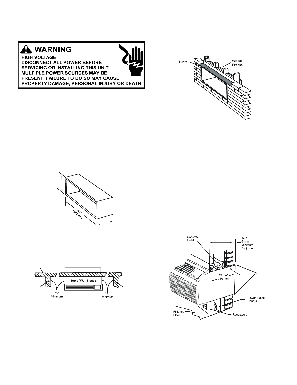
• The wall opening must be the correct size. See the figures
below for wall sleeve Dimensions and minimum wall opening size.
1
1
6
6
1
/
"
4
m
0
1
m
"
4
/
3
3
1
m
m
0
5
Wall Receptacle Within 58" From
Bottom R ight Side C orner on
208/230 VAC Units Only
3
• If installed in a concrete or masonry wall, a lintel must be
provided in the wall opening for support. Do not use the
wall sleeve as a lintel. See Framing with Lintel Figure
for a typical lintel construction.
Framing with Lintel
• When installed in the opening, the wall sleeve must be
horizontally level from side to side and pitched (one quarter bubble in the sight glass) to the outside. DO NOT INSTALL LEVEL (FRONT TO BACK) OR SLOPE THE WALL
SLEEVE TOWARD THE ROOM.
• The installer must determine and supply the mounting bolts
and/or screws to attach the wall sleeve to the sides of the
wall opening. Make sure the wall opening is adequate for
strong support.
• The installer must provide adequate sealing and insulation
around the sleeve after it is installed (air and water tight).
See Block and Brick Veneer Installation Figure for one of
many types of constructions.
13 1/2" (340 mm)
Maximum
(No Accessories)
Wall Sleeve Dimensions
Outside
Wall
Caulk Top,
Bottom, and
Both Sides
Internal
Adjacent
Wall
Allow Front Clearance (See Table 1)
Internal
djacent
Wall
Steel
Lintel
Minimum Unit Clearances
• The wall sleeve will need to be installed with minimum
clearances to the floor and adjacent walls. Minimum projections of the sleeve into and out of the room will also
have to be met. See Minimum Unit Clearances and Minimum Interior and Exterior Projections Figures as well as
Minimum Clearances and Projections table for details.
16
Block and Brick Veneer Installation

PROPER INSTALLATION
Minimum Interior and Exterior Projections
4
2
1
1
0
/
4
7
"
M
5
i
m
n
i
m
m
u
m
m
"
m
4
u
/
m
1
m
i
5
6
n
1
i
1
4
M
Dimension "B"
in Table 1
MINIMUM CLEARANCES AND PROJECTIONS
Minimum
Option
in. mm in. mm in. mm
Wall Sleeve Only 3 75 0 0 0 0
Subbase Kit 3 75 3 1/4 85 2 3/4 70
Leveling Legs Kit 3 75 3 75 2 50
Duct Kit 3 75 0 0 1 3/8 35
Drain Kit 3 75
Hard Wire Kit 3 75 1 1/4 30 0 0
Hydronic Heat Kit
"A" Series
Hydronic Heat Kit
"J" Series
1
If inside mounted then B = 1 1/2 inches (40 mm).
2
To achieve a flush fit between the hydronic front and the finished wall,
9 230
6 150 0 0 2 1/2 65
Clearances
ABC
1
0
0 to 3 1/4
3
1
0
0 to 85
Dimension “C” must be between 3” and 3 1/8”. If this dimension is more
than 3 1/8” there will be a gap between the front and the wall. This gap
could permit occupant access to hydronic lines or other dangerous parts.
3
This dimension can be from 0” to 3-1/4”, but cannot exceed 3-1/4”. If this
dimension exceeds 3-1/4”, the skirt around the front will not reach the
floor.
Minimum
Projection
00
3
32 752
• For installations in walls deeper than 13-1/2 inches, special care is necessary to prevent problems with rain water,
condensate drainage and intake/discharge air. Under these
circumstances, careful job site analysis and precautions
are required. You must consult with your Sales Representative and receive approval before attempting such installations.
• If used, a 230/208 volt wall receptacle must be located
within 58 inches of the lower right sleeve corner. Extension cords must not be used with the unit. See the note on
Wall Sleeve Dimensions Figure.
Minimum Wall Opening Dimensions
When 230/208 volt units are to be installed, the power supply
may be either cord connected or permanent wiring. Permanent
wiring may be done through the accessory hard wire junction
box, or the accessory subbase.
When 265 volt units are to be installed, the power supply must
be permanent wiring. Permanent wiring may be done through
the accessory hard wire junction box, or the accessory subbase. An exposed cord connection on 265 volt units is not
permitted.
The subbase accessory includes leveling legs. If added wall
sleeve support is required and the subbase is not to be used
as an accessory, leveling leg kit may be installed.
Drain Kit
An indoor/outdoor drain kit is available as an accessory item.
When a drain kit is to be installed, do so before installing the
wall sleeve in the wall. See the drain kit for actual installation
instructions.
Subbase, Leveling Legs, Main Duct, and Hydronic Heat
Kits
Installation of these kits requires drilling of mounting holes on
both sides of the wall sleeve. The minimum required clearance
distance between the wall sleeve and wall is shown in Minimum Clearances and Projections Table. If the distance between wall sleeve and wall will be at or near the minimum clearance distance, mount these kits on the sleeve before installing
the sleeve in the wall. The kit installation instructions are included with the accessory kits.
17
PROPER INSTALLATION
Wall Receptacle Within 58" From
Bottom R ight Side C orner on
208/230 VAC Units Only
Wall Sleeve Dimensions
Outside Enclosure Panel Removal
The sleeve stiffener must be taken out before the enclosure
panel can be removed from the sleeve.
The enclosure panel can be removed by folding the four flaps
up and downward and manipulating the front ends of the top
plus bottom towards the center. The entire panel can be pulled
out diagonally from one side.
Install the wall sleeve condenser air grille by using the screws
and holes provided.
Installation (WS900B or WS900D)
After the wall opening is checked and approved for location,
size, and clearances, complete the following to install the wall
sleeve.
NOTE: Check with Amana® Technical Service when a chassis
is installed in any wall sleeve not supplied by Goodman.
1. Remove the outside enclosure panel from the wall sleeve.
2. Slide the wall sleeve into the wall opening. Do not distort
the cabinet shape to fit the wall opening. The unit chassis
must fit snugly and uniformly into the wall sleeve.
3. Locate the sleeve within the range of minimum projections,
as shown in Minimum Wall Opening Dimensions and Minimum Interior and Exterior Projections Figures, so both
sides are at least the minimum projection from the wall.
4. Check the level of the wall sleeve. For proper drainage, the
sleeve should be level from side to side and one-quarter
bubble in the sight glass sloping to the outside.
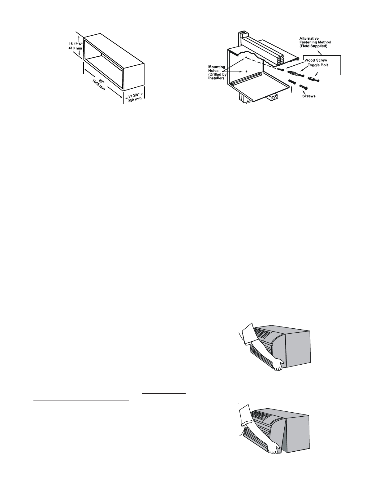
5. Two holes will need to be drilled in both sides of the wall
sleeve for mounting into the wall. Drill holes of proper size
and in the proper location so the screws will engage into
strong supporting members of the wall. DO NOT DRILL
THROUGH BOTTOM OF SLEEVE. The following figure
shows possible fastening methods.
Expansi on
Anchor Bolt
Plastic
Anchor
Attaching Wall Sleeve to Opening
6. Check the level of the wall sleeve and adjust if necessary.
7. Caulk or seal around the outside of the entire sleeve.
8. If the unit chassis will not be installed immediately, replace the enclosure panel on the outside opening of the
sleeve. This will prevent weather damage to the building
interior.
9. Recycle or dispose of packaging materials per local codes.
OUTDOOR GRILLE
An outside grille must be installed to direct air flow for proper
unit operation and also protect the outdoor coil. The grille must
be installed before installing the chassis. Refer to the Installation Instructions supplied with the outdoor grille kit for a complete description of the installation procedure.
This model requires either a Stamped Grille Kit (Model SGK-B) or an Architectural Grille Kit (Model AGK--B). When replacing an old chassis with an existing grille, please check with
your sales representative to determine if the new chassis should
be used with the old outdoor grille. An improper outdoor grille
can decrease cooling or heating capacity, increase energy
usage and shorten compressor life.
FRONT REMOVAL
1. Grasp the cabinet front as shown.
2. Pull the bottom of the cabinet front away from the chassis
until the retaining clips disengage.
18

PROPER INSTALLATION
3. Lift the cabinet front off the chassis. Reverse this procedure to reinstall the cabinet front.
CHASSIS INSTALLATION
1. Remove the cabinet front from the chassis as described in
Front Removal.
2. Insert the chassis into the wall sleeve.
Wall Sleeve
Chassis
Slide Chassis In
3. Slide the chassis into the wall sleeve until the chassis
flanges contact the front edge of the wall sleeve.
Outside
Wall
Wall Sleeve
Front Mounting Holes - Two mounting holes are provided to
give the owner the option of securing the front to the chassis.
The mounting holes are located behind the intake grille. The
owner must supply two 1/2 inch long #8 sheet metal screws
per unit. The two screws must be removed before the front can
be removed.
Mounting Screws
Location
Front Mounting Screws
WIRING
CAUTION
TO AVOID PROPERTY DAMAGE, PERSONAL INJURY
OR DEATH DUE TO ELECTRICAL SHOCK:
• DO NOT USE AN EXTENSION CORD WITH THIS UNIT.
• USE ONLY COPPER CONDUCTORS.
• WIRING TO THE UNIT MUST BE PROPERLY POLAR-
IZED AND GROUNDED.
Chassis
4. Secure the chassis to the wall sleeve using three screws
on each side of the chassis to ensure a proper seal between the chassis and the wall sleeve. The screws are
supplied in a plastic bag which is attached to the power
cord.
IMPORTANT NOTES:
1. The unit is equipped with a rubber grommet mounted compressor. These grommets are factory set and require no
adjustment.
2. If a standard subbase is used, be sure the right hand subbase cover is removed before the chassis is installed in
the sleeve.
3. Check the indoor and outdoor grilles for obstructions to air
flow. The unit must be located where curtains, furniture,
trees, shrubs or other objects do not block the air flow to
and from the unit. If air is obstructed and/or deflected back
into the unit, the air conditioner’s compressor may cycle
on and off rapidly. This could damage the compressor and
void the warranty.
Outside
Wall
Cord connection to a wall socket is not permitted for 265-volt
units. All 265-volt units must be hard wired using the hard wire
kit or make use of the plug-in receptacle in the standard subbase.
Heaterless Units
If a heaterless unit is ordered, field provisions must be made
for supplemental heat if desired. Refer to the Installation Instructions supplied with the heater kit for a complete description of the installation procedures. All 208/230 volt heaterless
units are shipped with a 15 Amp power cord and all heaterless
265 volt units are shipped with a 20 Amp power cord.
When adding a heater kit to a unit, the power cord supplied
with the heater kit must be used in place of the power cord
supplied with the unit. The following table specifies power cord
rating requirements for the various heater kits.
19
A
PROPER INSTALLATION
POWER CORD REQUIREMENTS
Heater Size
(kW)
1.5 15 20
2.5 15 20
3.5 20 Not Applicable
3.7 Not Applicable 20
530 30
230/208 Volt Units 265 Volt Units
Power Cord Rating
(amp)
Power Cord Rating
(amp)
NOTE: Heaterless units are shipped with an auxiliary data label
on the front side of the mid-partition panel. If an electric heater
kit is field installed, the installer must mark the appropriate
box on the label to indicate the electric heater capacity. If no
heater is installed, the box labeled “None” must be marked.
Refer to the unit nameplate for over current protection data.
CAUTION
DO NOT INSTALL A 5kW HEATER KIT IN ANY 7,000
OR 9,000 BTU CHASSIS.
Switch
Position
OFF
FAN ONLY Unit operates on low fan speed to circulate room air.
LOW COOL
HIGH COOL
LOW HEAT
HIGH HEAT
Unit is completely off. However, before servicing, open all
disconnects and/or remove plug.
Unit operates on the low fan speed to circulate air
for cooling.
Unit operates on high fan speed to circulate air
for cooling.
Unit operates on the low fan speed to circulate air
for heating.
Unit operates on the high fan speed to circulate air
for heating.
Unit Function
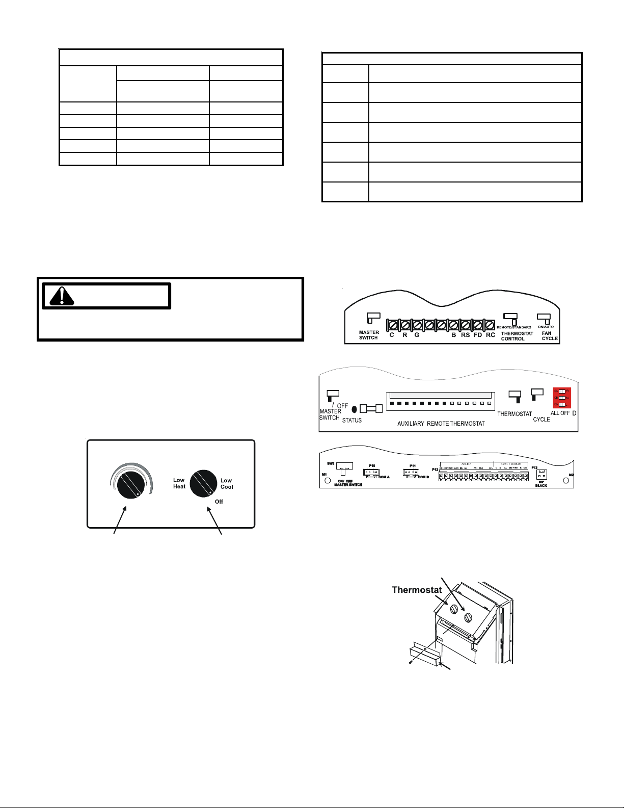
Additional Control Inputs (Not used on NTE or NTP Models)
The control inputs shown below provide addition unit control
and features. To access these control inputs, the cabinet front
must be removed (see Front Removal).
MODE SWITCH SETTINGS
ON/OFF
W2 Y\W1
OPERATING CONTROLS
Users Controls
Two rotary knobs controlling temperature and operational mode
are located behind the control door located to the top-right of
the cabinet front.
High
Heat
Warm Coo l
Thermostat
Thermostat Setting
Turning the thermostat control clockwise will provide a cooler
room temperature; turning it counterclockwise will provide a
warmer room temperature. Adjusting the thermostat to the mid
setting (vertical) will set the room temperature at approximately
75° F.
Mode Switch
The table below describes the unit function corresponding to
the various mode switch settings.
Fan
Only
Mode Switch
High
Cool
C
ON
LED1
EH
IN LS FD1
FD2 TF1 TF2 C R GL W2 Y/W1B GH
ON/AUTO
RMT/STD
CONTROL
TF-
LS
FAN
B
Furthermore, to access the 24V accessory input connections,
the terminal strip cover must be removed as shown (A and B
Series units only).
Mode Switch
Terminal Strip
Cover
Master Switch (Not used on NTE or NTP Models)
The master switch disconnects power to all of the system components. When this switch is in the off position, the compressor, fan motor, reversing valve, and electric resistance heater
will all be de-energized.
20

PROPER INSTALLATION
s
X1
B
Y
Y/W1
W2
Control Board
Connections
Y/W1
W2
W1
W2
Thermostat
Connections
W1
W2
14 Pin
Connector
EH LS
Control Board
Connections
Thermostat
Connections
R
C
Control Board
Connections
14 Pin
Connector
LS
EH
Control B oard
Connection
Thermostat
Connections
B
Y
Thermostat
Connections
18 Pin Connector
R*
18 Pin Connector
21

PROPER INSTALLATION
A
REMOTE/STANDARD SWITCH (NOT USED ON NTE OR
NTP MODELS)
The remote/standard switch is used to change the control of
the unit from the standard on board controls in the standard
mode, to a remote wall mounted thermostat in the remote mode.
For remote control operation refer to Remote Operation section. To set remote switch on the "G & K" board, see
Configuration Settings.
Fan Cycle Switch
The fan cycle switch sets the operational mode of the fan. In
the ON position, the fan will run continuously whenever the
unit is in the heat or cool mode. In the AUTO position, the fan
will cycle on and off with the compressor or electric heater
when the unit is in the cool or heat mode.
Remote Control Inputs (Not used on NTE or NTP Models)
The C, R, G,(GL for low fan speed or GH for high speed fan on
"C Models and later") W2, Y/W1 and B terminals provide control inputs for a remote wall mounted thermostat. See sche-
matics page 20.
IMPORTANT NOTE: Disconnect power to the unit and/or turn
the Master Switch on the control board to OFF when connecting or altering wiring to any terminal. Failure to do so may
result in shorting the fuse or damaging the control board.
Front Desk Control (Not used on NTE or NTP Models)
The FD and RC terminals or FD1 and FD2 provide control inputs for a front desk switch. Shorting across these two terminals will disable unit operation. The only control function which
will remain active when these terminals are shorted is freeze
protection. Any switch which will produce a short circuit across
these two terminals can be used as a front desk switch. The
contact resistance of the switch, when closed, must be less
than 200 ohms for the front desk feature to operate properly.
The following table shows the maximum wire length and corresponding gage size for installation of a front desk switch.
MAXIMUM WIRE LENGTH
FOR FRONT DESK SWITCH
Wire Size
(AWG)
#24 400
Maximum
Length Allowed
(ft)
ON/OFF
W2 Y\W1
Front Desk
Switch
ON / AUTO
B
1 1 1 + 1
RMT/STD
THERMOSTA T
Front Desk Switch Wiring Schematic
IMPORTANT NOTE: Do not apply 24VAC across these ter-
minals. Applying 24VAC to these terminals will result in failure
of the control board. Shorting these terminals to any other terminals may also result in control board failure.
Remote Temperature Sensing (Not used on NTE or NTP Models)
The RS and RC terminals provide control inputs for a remote
temperature sensor.
Remote
Sensor
23
#22 600
#20 900
#18 1500
#16 2000
CRGW2 BRSFD
The figures below shows a wiring schematic for connecting the
front desk switch to the unit.
“C” Models or Later
1. Remove indoor ambient thermistor from plastic holder on
indoor coil.
22

PROPER INSTALLATION
A
Indoor Ambient
Thermistor
Plastic
Holder
Indoor Coil
2. Cut off end of thermistor, separate leads 1” back from cut
and strip 1/2” of insulation from each lead.
3. Wire nut the stripped leads to the two sensor wires running from terminals 2 and 3 on the remote temperature
sensor base .
68° F71° F
75° F
82° F
85° F 87° F
Low End
Cooling Limits
64° F
87° F
69° F
76° F
Heating Limits
63° F66° F
63° F
86° F
79° F 83° F
High End
Temperature Limiter Settings
The temperature limits are set by selecting the proper holes to
use for the limiter screws. The figure above shows the high
and low end temperatures corresponding to the various limiter
holes. Since these temperatures correspond to the unit's thermistor sensor, actual room temperatures will vary depending
on the room heating/cooling load. For example, if the limiter
screws are put in the shaded holes, the coolest setting in the
cooling mode will be 68° F and the warmest setting in the
heating mode will be 83° F."A & B model units only, C mod-
els and later have DIP Switches to set the limits"
Temperature Limiter
4.Place the mode switch in the “OFF” position. Reestablish
power to the unit. The remote temperature will automatically activate.
NOTE: Ensure the mode switch is in the OFF position before
electrical power is applied to the unit. If the mode switch is not
in the OFF position when electrical power is applied to the unit,
the random restart feature will activate causing a two to four
minute start-up delay.
NOTE: Freeze protection temperatures will be sensed by the
remote temperature sensing device and not at the PTAC unit
(sensed at the PTAC unit when a remote thermostat is used).
Temperature Limiter
The temperature limiting feature can reduce energy costs by
controlling the maximum temperature available in heating and
the minimum temperature available in cooling. While approximate temperature settings are shown below, actual room temperature will vary slightly.
C
ON
LED1
EH
IN LS FD1
FD2 TF1 TF2 C R GL W2 Y/W1B GH
RMT/STD
CONTROL
ON/AUTO
FAN
B
POSITION COOL HEAT
A 70-78 65-73
B 68-81 63-76
C 66-83 61-78
D 63-88 58-83
Temperature Settings
NOTE: Select only on pin position.
After determining the temperature limits desired, set the limiter as follows:
1. Remove the front cabinet (see Front Removal) to allow access to the control panel.
2. Remove the unit control knobs by pulling the knobs off the
control shafts.
3. Remove the escutcheon plate by lifting it off the control
panel cover to expose the temperature limiter as shown.
23

PROPER INSTALLATION
Tem perat ure
Limiting Screws
Temperature Limiter
4. Remove the two screws supplied in the top of the control
panel cover, and drive them into the desired limiter holes.
5. Replace the escutcheon plate, control knobs and front.
NOTE: To achieve maximum efficiency, it may be necessary
to change the temperature limiter screws seasonally.
Users Controls "Digital Touch Pad"
A six button touch key pad located behind the control door
controls both temperature and operation mode. The key pads
can be used alone or in combination.
Diagnostic Light
The green diagnostic light located in the lower left hand corner
of the touchpad and indicates operation warnings. This light
usually indicates that either the filter or coils need cleaning.
Please refer to the Maintenance and Cleaning section for the
proper cleaning procedure. If this light is still on after cleaning,
please refer to the Diagnostic & Status Report section for assistance.
Additional Control Inputs
The control inputs provide additional unit control and features.
To access these control inputs, the cabinet front must be removed (see Front Removal).
Master Switch
The master switch disconnects power to all of the system components. When this switch is in the off position, the compressor, fan motor, reversing valve, and electric resistance heater
will all be de-energized.
WARNING
Status LED
User Controls
Thermostat Setting
Pressing the COOL thermostat control and the up or down
arrows will provide a cooler room temperature, respectively.
Pressing the HEAT thermostat control and the up or down arrow keys will provide a warmer room temperature.
Fan Speed
The fan speed touch key will deliver high, low or auto fan speed
to circulate room air. NOTE: The AUTO selection will not be
available if a fan speed is selected without COOL or Heat selection.
Fan Operation HIGH or LOW with HEAT or COOL mode selected - The selected fan speed shall run in the selected speed.
Fan Operation AUTO with HEAT or COOL mode selected - The
fan will run in low and high speed. The changes in fan speed
are automatic. See "Configuration Settings" section for further
details.
Remote Control Inputs
The C, R, GL, W2, Y/W1, B/O, and GH terminals provide control inputs for a “manufacturer-approved” remote wall mounted
thermostat. The “B” terminal can be configured to become “O”
if needed see Configuration Settings For remote control thermostat operation, refer to the Remote Thermostat Operation
section.
Vent Control
NOTE: Vent control is only used on units with the power vent
or power vent door kit not installed.
The vent control allows fresh air to be drawn into the conditioned area. This fresh air can provide ventilation when the blower
is operating, but it will increase the heating or cooling load and
operating costs.
To obtain access to the vent control, remove the cabinet front
(see Front Removal). Remove the shipping screw (if installed)
from the vent door. Then remove the label (if present) from over
the vent control lever on the left side of the chassis.
24
 Loading...