


111990"" Automatic Dryers
Maytag 111990"" Automatic Dryers, D9900, D9800, D9700, D8600 Service Manual
...
Maytag
111990"
Automatic
Dryers
Service
Manual
16000132
Issued
1990
Revised
2/98

Contents
SECTION 1. ELECTRICAL TEST EQUIPMENT "
1-1
APPLIANCE TEST METER
1-1
CLAMP-ON AMMETER
'.
. . . . . . . . . . . . . . . . . . . . . . .
..
1-3
MOTOR TEST CORD 1-4
VOLTAGE CHECKS 1-5
TEMPERATURE READINGS RANGE (50°F.
to
300°F.) 1-6
SECTION 2. ELECTRICAL - MECHANICAL TROUBLESHOOTING
2-1
WILL NOT RUN
2-1
WILL NOT DRY ' 2-2
WILL NOT SHUT OFF
,...............................
2-2
MISCELLANEOUS
,...................................
2-6
MICROPROCESSOR
BOARD
CONTROL MODELS 2-7
DRYER (MICROPROCESSOR BOARD CONTROL)
2-11
FAULT CODE 2-15
SECTION 3. SERVICE PROCEDURES
3-1
ACCESS
TO
CONTROL PANEL COMPONENTS
3-1
CONTROL PANEL ASSEMBLY COMPONENTS
3-1
MICROPROCESSOR
BOARD
CONTROL 3-10
FRONT PANEL AND COMPONENTS 3-13
TUMBLER AND RELATED COMPONENTS 3-17
THERMOSTATS 3-24
BLOWER
3··27
DRIVE MOTOR
AND
IDLER ASSEMBLY
,........................
3-28
HEATING ELEMENT
AND
RELATED COMPONENTS -- ELECTRIC MODELS
3-31
GAS VALVE AND RELATED COMPONENTS 3-34
CABINET AND TOP COVER
3-41
SECTION 4. PRE-INSTALLATION CONSIDERATIONS
4-1
LOCATING DRYER
4-1
EXHAUSTING 4-2
ADJUSTING
MAIN
BURNER 4-6
ELECTRICAL REQUIREMENTS 4-8
ELECTRICAL CONNECTIONS 4-10
A!?DITIONAL INFORMATION 4-12
PERSONAL SAFETY PRECAUTIONS
'.'
. .
..
4-12
SECTION 5. GENERAL INFORMATION
5-1
HEAT SOURCE
5-1
MODEL CHART 5-2
SCHEMATICS 5-3
ED/GD401 1090 Contents

ED/GD401 1090
Contents
ii
INTRODUCTION
This service manual is
intended
to assist
youindiagnosing
conditions
which
may
develop. Electrical
component
testingisfor
the
most part,
made
with
an
appliance
test
meter
and consists of checking
for
open
or
closed circuits. Mechanical checks
are
made
through
sight
and sound,
along
with
the
use of a clamp-on ammeter.
This
manualisdesigned
for
the
technician
whoisfamiliar
with
the
operation
and
construction
of
May
tag
products.
Information
containedinthis
manualisintended
for
use
byaqualified
service
technician,
familiar
with
proper
and
safe
procedures
to
be
followed
when
repairing
an
electrical
appliance.
All
tests
and
repairs
should
be
performed
byaqualified
service
technician
equipped
with
proper
tools
and
measuring
devices.
All
component
replacements
should
be
made
byaqualified
service
technician,
using
only
MA
yeOR
replacement
parts.
Improper
assembly
or
adjustment
may
occurifservice
or
repairisattempted
by
persons
other
than
qualified
service
technicians
orifparts
other
than
MA
yeOR
replacement
parts
are
used.
Improper
assembly
or
adjustment
can
cause
haz-
ardous
conditions.
There can
be
riskofinjury
or
electrical
shock
while
performing
services
or
repairs.
Injury
or
electrical
shock
can
be
serious
or
even
fatal.
The
first
and
most
important
stepofany
service
call istoaccurately
determine
what
the
complaint
is. This is best
accomplished
by
questioning
the
customer,
finding
out what
the
prodUct isorisn't
doing
and why
they
feel a
problem
exists.
Section 1 covers Electrical Test Equipment. This sections also
covers
general use
of
the
equipment;
an
Appliance
Test Meter, Clamp-On
Ammeter
and
Motor
Test
Cord.
Section 2
covers
Electrical-Mechanical
Troubleshooting
and a
listofpossible
com-
plaints. Find
the
complaint
which
you
feel best matches that
provided
by
the
cus-
tomer
and
turntothe
appropriate
page(s). You
will
find a
listofpossible
electrical
and mechanical
problems
for
the
complaint,
which
have been listedinthere
order
\
of:
1.
Easeinchecking.
2.
Probability.
ED/GD401 1090 INTRODUCTION Iii
Systematically
eliminating
these
possibilities
will
allow
youtofind
and
correct
the
problem.
Section 3
covers
Service
Procedures.
This
section
will
provide
information
on
locationofcomponents,
disassembly
and/or
reassembly
procedures,
the
purpos,e
and/or
functionofthe
part
andinsome
instances
specific
checkstobe
made.
Section 4
covers
Pre-Installation
Considerations.
This
provides
information
on
location
and
exhaustingofdryer,
main
burner
adjustment,
electrical
requirements
and
connections.
Section 5
covers
General
Information.
This
section
covers
brief
specifications,
cycle
descriptions
and
schematics.
\
....
ED/GD401 1090
INTRODUCTION iv
SECTION 1. ELECTRICAL TEST EQUIPMENT
The
equipment
required
to
service
May
tag
products
depends
largely
upon
the
condition
encountered.
Locating
a
malfunction
will
often
require
the
use
of
electrical
testing
equipment
such as:
•
Appliance
Test
Meter
•
Clamp-on
Ammeter
•
Motor
Test
Cord
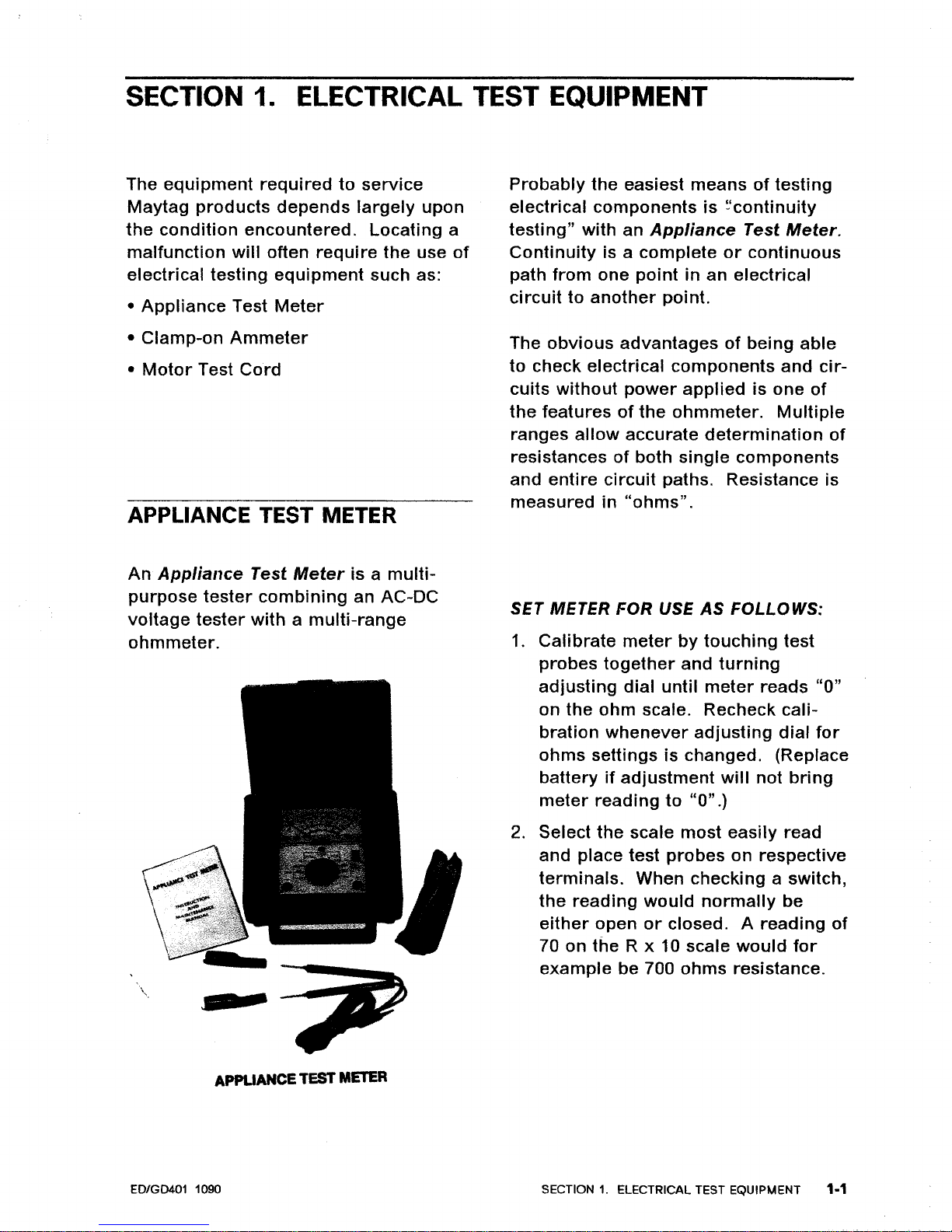
APPLIANCE TEST METER
Probably
the
easiest
meansoftesting
electrical
components
is
~'continuity
testing"
with an
Appliance
Test
Meter.
Continuity
is a
complete
or
continuous
path
from
one
point
in an
electrical
circuittoanother
point.
The
obvious
advantagesofbeing
able
to
check electrical
components
and
cir-
cuits
without
power
applied
is one
of
the
featuresofthe
ohmmeter.
Multiple
ranges
allow
accurate
determination
of
resistancesofboth
single
components
and
entire
circuit
paths. Resistance is
measuredin"ohms".
An
Appliance
Test
Meter
is a
multi-
purpose
tester
combining
an AC-DC
voltage
tester
withamulti-range
ohmmeter.
\
SF
2
APPLIANCE
TEST
METER
SET METER FOR USE
AS
FOLLOWS:
1.
Calibrate
meter
by
touching
test
probes
together
and
turning
adjusting
dial
until
meter
reads
"0"
on
the
ohm
scale. Recheck
cali-
bration
whenever
adjusting
dial
for
ohms
settingsischanged. (Replace
battery
if
adjustment
will
not
bring
meter
reading
to
"0".)
2.
Select
the
scale
most
easily
read
and place test
probes
on respective
terminals.
When checking a switch,
the
reading
would
normally
be
either
open
or
closed. A
reading
of
70 on
the
R x 10 scale
would
for
example
be 700
ohms
resistance.
ED/GD401 1090
SECTION1.ELECTRICAL TEST EQUIPMENT 1-1
~f~
~.,~"]
Q
CAUTION
---------------,
Always
be
sure
the
power
has been
disconnected
before
making
resist-
ance
measurements.
Failuretodo
so
will
resultindamagetoyour
meter! Internal
batteries
provide
all
the
power
needed to make resist-
ance checks. They
should
be
checked at least once a
year
and
replaced as needed.
For
the
most
part, we
will
only
be
con-
cerned
with
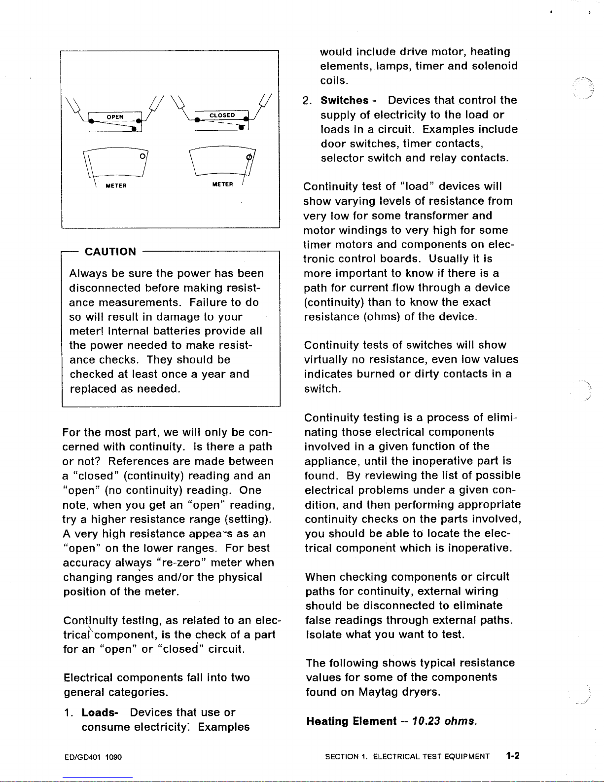
continuity.
Is
there
a path
or
not? References
are
made
between
a
"closed"
(continuity)
reading
and an
"open"
(no
continuity)
reading.
One
note,
when
you
get an
"open"
reading,
tryahigher
resistance
range
(setting).
A
very
high
resistance
appea~s
as an
"open"
on
the
lower
ranges.
For
best
accuracy
alw~ys
"re-zero"
meter
when
changing
ranges
and/or
the
physical
positionofthe
meter.
Continuity
testing,
as
related
to an elec-
\
tricarcomponent,
is
the
checkofa
part
for
an
"open"
or
"closed"
circuit.
Electrical
components
fall into
two
general
categories.
1.
Loads-
Devices
that
use
or
consume
electricity:
Examples
ED/GD401 1090
would
include
drive
motor,
heating
elements, lamps,
timer
and
solenoid
coils.
2.
Switches
- Devices
that
control
the
supplyofelectricity
to the load
or
loads
in a
circuit.
Examples
include
door
switches,
timer
contacts,
selector
switch and
relay
contacts.
Continuity
testof"load"
devices
will
show
varying
levelsofresistance
from
very
low
for
some
transformer
and
motor
windingstovery
high
for
some
timer
motors
and
components
on elec-
tronic
control
boards.
Usually
it is
more
importanttoknowifthere
is a
path
for
current
.flow
throughadevice
(continuity)
thantoknow
the
exact
resistance (ohms)
of
the
device.
Continuity
testsofswitches
will
show
virtually
no resistance, even
low
values
indicates
burned
or
dirty
contacts in a
switch.
Continuity
testingisa
processofelimi-
nating
those
electrical
components
involved
in a
given
functionofthe
appliance,
until
the
inoperative
part
is
found.
By
reviewing
the
listofpossible
electrical
problems
underagiven
con-
dition,
and
then
performing
appropriate
continuity
checks
on
the
parts
involved,
you
should
be
able
to locate
the
elec-
trical
component
whichisinoperative.
When checking
components
or
circuit
paths
for
continuity,
external
wiring
should
be
disconnectedtoeliminate
false
readings
through
external
paths.
Isolate what
you
wanttotest.
The
following
shows
typical
resistance
values
for
someofthe
components
found
on
May
tag
dryers.
Heating
Element
-- 10.23
ohms.
SECTION1.ELECTRICAL TEST EQUIPMENT 1-2
Gas
Valve
Disconnect
radiant
sensor
and
igniter
wires.
Measure
across
igniter
wires
or
igniter
plug
from
valvetoget a
resist-
ance
valueof-- 425-450
ohms.
Measure
across
sensor
wires
to get a
resistance
of
-- 450-475
ohms.
Drive
Motor
Red
terminal
to
Gray
terminal
-- 1.5
ohms.
In
order
to
measure
the
individual
windings
the
red
and
gray
wires
will
havetobe
pulled
offofthe
start switch.
Run
winding
only
-- 2.25
ohms.
Start Winding
only
-- 3
ohms.
Glow
Bar
Igniter
Becauseofthe
make-upofthe
igniter,
the resistance
will
vary
overarather
wide
range. Values
from
180
ohms
to
400
ohms
would
be
typical
with
an
igniteratroom
temperature.
These
values
are
provided
so
that
you
may
have
an
ideaofthe
resistance
that
you
can see in
testing.
These resist-
ances
are
not
meanttobe used as the
exact
valuestodetermine
whether
a
t;omponent
should
be replaced. They
\
are
provided
so
that
you
may
have
an
ideaofthe
resistance
that
you
can see
in
testing
components.
EDIGD401 1090
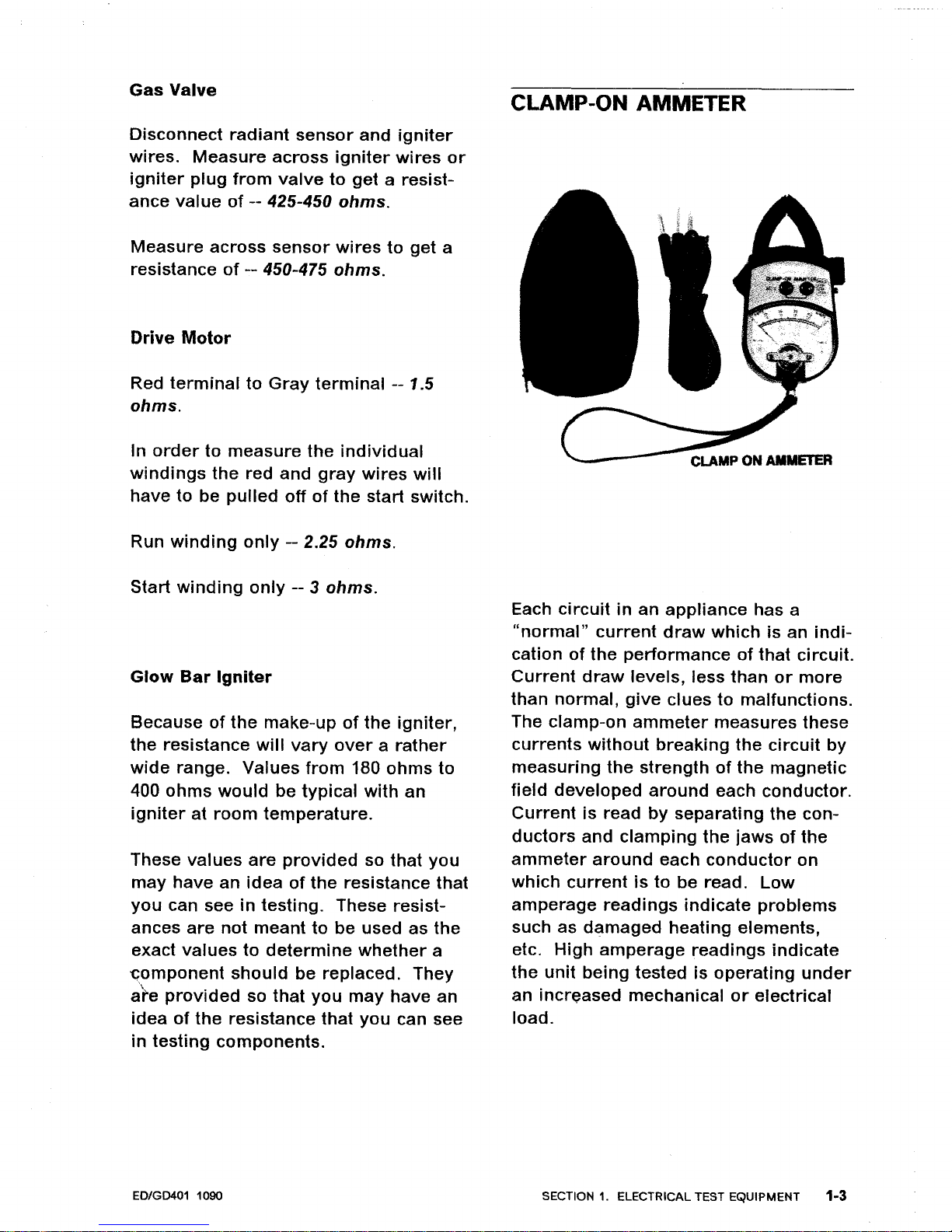
CLAMP-ON
AMMETER
Each
circuitinan
appliance
has a
"normal"
current
draw
which
is an
indi-
cationofthe
performanceofthat
circuit.
Current
draw
levels, less
than
or
more
than
normal,
give
cluestomalfunctions.
The clamp-on
ammeter
measures
these
currents
without
breaking
the
circuit
by
measuring
the
strengthofthe
magnetic
field
developed
around
each
conductor.
Current
is read
by
separating
the
con-
ductors
and
clamping
the
jawsofthe
ammeter
around
each
conductor
on
which
currentisto
be read.
Low
amperage
readings
indicate
problems
such as
damaged
heating
elements,
etc.
High
amperage
readings
indicate
the
unit
being
tested is
operating
under
an
increased
mechanicalorelectrical
load.
SECTION1.ELECTRICAL TEST EQUIPMENT
1·3
Note:
Overloads
onacircuit
breaker
or
fuse can be
tracedtothe
product
being
tested
or
the
circuit
breaker
(or
fuse) by
checking
the
product's
current
draw.Ifthe
amperage
reading
is less
than
the
breaker
reading,
the
breaker
or
fuse
box
is at fault.
USE
OF
AMMETER
ON
DRYER
There
are
two
currentsofconcern
to
us
in an
electric
dryer;
the
heating
element
current
and
the
drive
motor
current.
These
currents
can be meas-
ured
by useofa
"split
line
cord"
exten-
sion
for
the
dryer
cord
or
by
attaching
the
ammetertothe
respective
power
line
wiresatthe
dryer
terminal
block.
Current
measured
should
be
21
amps
on
the
heating
element
sideofthe
line,
24
amps
on
the
drive
motor
sideofthe
line
and4amps
on
the
center
or
neutral
line.
A
\".
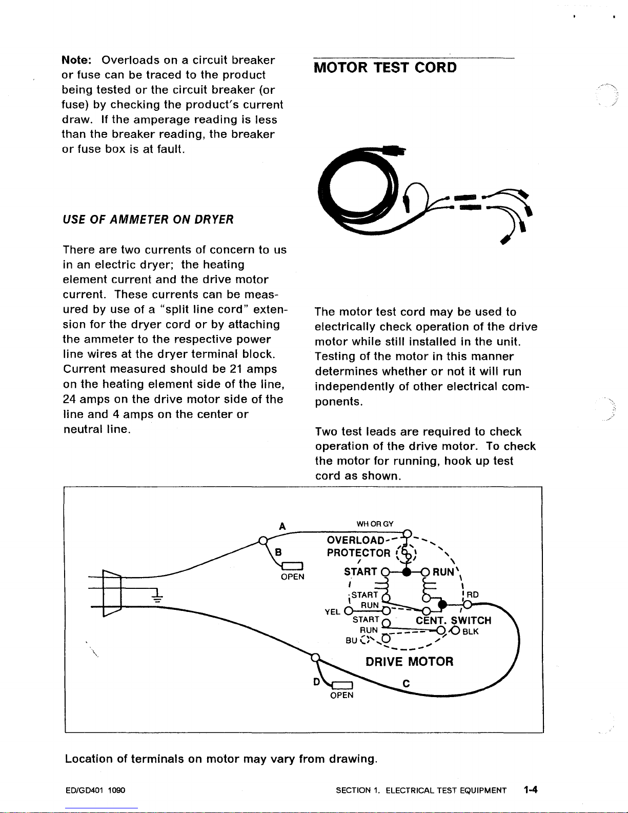
MOTOR TEST CORD
The
motor
test
cord
may
be used.
to
electrically
check
operationofthe
drive
motor
while
still
installedinthe
unit.
Testing
of
the
motorinthis
manner
determines
whether
or
notitwill
run
independently
of
other
electrical
com-
ponents.
Two test
leads
are
required
to
check
operationofthe
drive
motor.
To
check
the
motor
for
running,
hook
up
test
cord
as
shown.
WHORGY
OVERLOAD'-
,
PROTECTOR ( "
, \
START
RUN'
\
I \
,START
: AD
YEL
0 RUN
0---
I
START Q . CENT. SWITCH
~~N
0-----
-q-oBLK
BU
....
,',
...
/
..........
__
....
DRIVE MOTOR
Locationofterminals
on
motor
may
vary
from
drawing.
ED/GD401 1090 SECTION
1.
ELECTRICAL TEST EQUIPMENT 1-4
CHECKING
HEAT
CONTACTS,
MOTOR
CENTRIFUGAL
SWITCH
1.
Disconnect
dryer
power
source.
2.
Gain accesstomotor
and
remove
blue
and
black
leads
from
motor
switch.
3. Use
eitherofthe
following
test
methods
using
appropriate
caution.
A.
Live
test
-- USE
CAUTION
1.
Usingadouble
insulated
spade
con-
nector,
connect
blue
and
black
wires
removed
from
motor
switch.
2. Reconnect
dryer
to
power
and
set
for
heat cycle.
3. Start
dryer,ifheat is
produced,
replace
motor
switch
on
motor.
If
no heat,
continue
additional
circuit
checks.
B.
Continuity
Check
(Insulate
wires
removed
from
motor
sWitch.)
1.
Using
clip
adapters,
attach
meter
probestothe
blue
and
black
motor
switch
terminals.
2.
Arrange
probe
leads
away
from
any
moving
parts
and
set
meter
on
RX1
range.
3.
Reconnect
dryer
to
power
source
and
start
dryer,
continuity
on
meter
indicates
good
switch. No
conti-
nuity,
replace
motor
switch
or
motor.
4.
Open
door
to
stop
dryer.
When
\
motor
stops,
motor
switch
contacts
must
open,ifnot
replace
switch
or
motor.
ED/GD401 1090
VOLTAGE CHECKS
For
the
most part
these
checks
will
consistoftaking
readingsatthe
wall
receptacleinorder
to
delermine
the
availability
of
voltagetothe
product.
Voltage checks on
individual
compo-
nentsofa
product
are
not
recom-
mended
duetothe
possibility
of
electrical
shock.
Component
part
testing
is best
accomplished
through
continuity
checks
with
an
Appliance
Test
Meter.
Note:
Useofthe
meter
on
voltage
higher
than
the
indicated
range
may
cause
permanent
damagetothe
meter.
To
prevent
damage,
first
select
highest
range
for
readings
which
fall
within
the
lower
scale.
SET UP METER FOR USE
AS
FOLLOWS:
1.
Turn
selector
knobtodesired
meter
function
and
appropriate
range.
2.
Plug
black
lead
into
socket
marked
-
(negative).
3. Plug red
lead
into
socket
marked
+
(positive).
4.
Place test
leads
into
receptacle
in
order
to
determine
voltage
avail-
able.
SECTION1.ELECTRICAL TEST EQUIPMENT 1-5
TEMPERATURE READINGS
RANGE
(50°F. to 300°F.)
Air
temperature
readings
can be taken
at
the
lint
filter
by
removing
the
filter
and
placing
the
accessory
temperature
probe
(Part NO. 38562)
directlyinthe
lint
filter
opening.
Cyclingofthe
ther-
mostats can
actually
be
observed
as
can the
temperatureofthe
exhausted
air.
SET UP METER FOR USE
AS
FOLLOWS:
1.
Turn
selector
knob
to TEMP.
2.
Insert
black
negative
leadoftemper-
ature
probe
into
socket
marked
-
(negative).
3.
Insert red
positive
leadoftemper-
ature
probe
into
socket
marked
+
(positive).
4.
To
calibrate
meter,
touch
black
plug
from
red
positive
leadtoblack
nega-
tive
lead
and
turn
calibration
dial
until
needle
aligns
with
CAL.
5.
Probeisreadytouse -- read
blue
scale
on
meter
face
marked
TEMP.
ED/GD401 1090
SECTION
1.
ELECTRICAL TEST EQUIPMENT 1-6
SECTION
2.
ELECTRICAL - MECHANICAL
TROUBLESHOOTING
WILL NOT RUN
Dryer
won't
start
or
run.
•
All
wires
are
hooked
uptotheir
corre-
sponding
terminals.
•
Dryerisplugged
in.
•
Blown
fuseorcircuit
breaker.
•
Door
switch.
•
Push-to-start
switch.
•
Timer.
•
Drive
motor.
•
Thermal
fuse.
Drive
motor
runs--drum
won't
turn.
•
Belt
offorbroken.
•
Motor
pulley
loose
or
off.
•
Idler
tension
spring.
•
Idler
pulley.
Dryer
runsafew
minutes
and
then
stops
--Motor
overload
protector
opens.
•
Lint
build-up
around
drive
motor.
•
Low
voltage.
•
Blower
impeller
blocked.
e,
Drive
motor.
\\.
Dryer
blows
fuses
or
trips
circuit
breaker.
Electric
Models
• The
amperage
readings
areat240
volts.
One
line
will
be
24
amps
and
the
other
line
will
be
21
amps.
The
neutral
line
will
beat4
amps.
If
you
have
the
above
amperage
readings,
the
problemisnot
the
dryer.
Check
the
fuse
box,
circuit
breaker
or
house
wiring.
•
Shorted
heating
element.
•
Incorrect
wiring
orawire
shorting
to
ground.
•
Drive
motor.
Gas
Models
•
During
ignition
the
dryer
will
draw
7
amps.
With
the
burner
on,
the
dryer
will
draw
4.5
amps.
If
the
dryer
is
drawing
the
above
amperage
and
the
fuse
blows,
the
problemisnot
the
dryer.
Check
the
fuse
box,
circuit
breaker
or
house
wiring.
•
Igniter.
•
Incorrect
wiring
orawire
shorting
to
ground.
•
Drive
motor.
CAUTION
---------------------------,
Always
disconnect
power
supply
before
making
any
continuity
checks
or
resist-
ance
readings.
ED/GD401 1090
SECTION2.ELECTRICAL - MECHANICAL TROUBLESHOOTING
2.,.1
WILL NOT DRY
Dryer
won't
heat
(motor
runs).
ELECTRIC MODELS
•
Blown
fuseortripped
circuit
breaker.
• Open
heating
element.
•
Hi-limit
thermostat.
•
Regulating
thermostat.
•
Temperature
selector
switch.
• Timer.
• Cycle
selector
switch (where used).
•
Drive
motor
start
switch.
Improper
Drying--Clothes
Wrinkled
--
Harsh
-- Taking
too
long
•
Lint
filter
is clean.
• Restriction in exhaust.
• Exhaust
hood
door
stuck.
• Exhaust
too
long.
•
Poor
make-up
air.
•
Incorrect
drum
speed.
Adjust
motor
pulley
or
wrong
motor
pulley.
•
Blower
impeller
bound.
•
Be
sure
elementorgas
valve
cycles
on and off.
•
Shorted
heating
element-electric
dryers
only.
•
Customer
ove'tloading
dryer.
• Check
clothing
labels
for
fabric
content.
WILL NOT SHUT OFF
Time
Dry
Models
•
Timer
motor.
• Timer.
AUTO DRY MODELS
• Set
timer
for
time
dry.
Check
voltage
across
timer
motor.Iftimer
will
not
advance, replace
timer.
• When
valve
or
element
cycles off,
should
have
powertotimer
motor,
if
not,
proceed
with
next
check.
•
Dryer
cycling
on
hi-limit
thermostat.
Check
following.
•
Lint
filter
clean.
•
Restriction
in exhaust.
• Exhaust
hood
door
stuck.
• Exhaust
too
long.
•
Regulating
thermostat.
•
Customerisoverloading
dryer.
ELECTRONIC CONTROL MODELS
The
electronic
control
and
timer
are
usedtocomplete
the
drying
cycle
and
cool-down
period
for
these
dryer
models.
The
dryer
starts
out
with
the
drive
motor
running,
the
timer
motor
running,
the
heat
cycling
and
the
elec-
tronic
control
disabled.
As
the
timer
advancestoa
certain
pointinthe
cycle,
CAUTION
-------------------------,
Always
disconnect
power
supply
before
making
any
continuity
checks
or
resist-
ance
readings.
ED/GD401 1090
SECTION
2.
ELECTRICAL - MECHANICAL TROUBLESHOOTING 2-2
the
electronic
control
becomes
opera-
tional
as cam
number
two
opens. A
short
time
later,
the
timer
motorisde-
energized
when
cam
number
one
for
the
timer
motor
opens.
It is
during
this
stall
period
that
the
electronic
control
system uses
the
wet
clothes
falling
across
the
sensorinthe
drum
to
dis-
charge
the
capacitor
and
keep
the
dryer
running.
There
are
three
dryness
levels;
More
Dry,
Normal
Dry
and
Less Dry. These
dryness
levels
have been
accomplished
by
placing
resistors
on
the
electronic
control
(printed
circuit
board)
and
routing
the
bypass
wiring
accordingly.
The levelofresistanceinthe
circuit
,
determined
by
the
dryness
level
selected, affects
the
charge-up
rate
of
the
capacitor
and
accomplishes
the
desired
dryness
level.
As
the
clothes
get
dry,
the
capacitorisabletobuild
up a
chargetoa
point
where
the
neon
bulb
fires,
thus
triggering
the
gate on a
SCR. When
this
happens,acircuit
is
made
through
the
SCR,
energizing
the
coilinthe
relay. This
takes
onlyasplit
second
and
the
relay's
coilisthen
held
energized
through
a setofcontacts
in
the
relay.
Also,
when
the
coilinthe
relayisener-
gized,
the
timer
motorisactivated
through
another
setofcontactsinthe
relay. The
timer
advances
and
opens
cam
number
three
for
the
heater
and
the
dryer
beginsatimer
controlled
CAUTION
cool-down
period.
The
amountofcool-
down
time
will
depend
upon
the
cycle
selected:
Regular
- 6
minutes,
Permanent-Press
- 13
minutes
and
Permanent-Press
with
Press
Care
- 33
minutes.
NOTE:
These
times
are
approximate.
The
timer
then
advances
to
where
cam
number
1A opens,
de-
energizing
the
drive
motor
and
the
cycle
ends.
TROUBLESHOOTING
When
the
dryer
does
not
go
into
cool-
down
and
shut
off with
dry
clothes,
you
needtoknow
whether
you
have a
control
problem
orasensor
problem.
Troubleshooting
the
electronic
control
is
made
easierifwe
break
the
circuit
down
into
parts. We can
separate
the
two
parts
by
disconnecting
the
W-BU
wireinthe
control
panel at
the
plastic
coupler.
The
upper
part
contains
the
electronic
control
assembly
which
con-
sistsofthe
edgeboard
connector
assembly,
printed
circuit
board
assembly
and
relay. The
lower
part
consistsofthe
sensor
assembly
located
on
the
tumbler
front
bulkhead.
Separating
the
two
areas
by
pulling
the
wires
apartatthe
coupler
will
show
where
the
problemislocated.Ifthe
dryerisstarted
without
any
clothes
in
the
drum
and
shuts
offinabout
20
minutes
without
the
sensor
circuit
hooked
up,
then
the
sensor
must
be
keeping
the
dryer
from
shutting
off.
Always
disconnect
power
supply
before
making
any
continuity
checks
or
resist-
ance
readings.
ED/GD401 1090 SECTION
2.
ELECTRICAL - MECHANICAL TROUBLESHOOTING
2-3

NOTE:
This
amountoftimeisfor
Regular
Fabrics
onaLess
Dry
setting.
A
settingofNormal
Dry
or
More
Dry
will
add
more
time
before
the
dryer
shuts
off. If
the
dryer
does
not
shut
off,
then
the
problem
is in
the
electronic
control
assembly.
Sensor
Assembly
1.
Disconnect
power
supply.
2.
Remove
front
panel.
3.
Remove
wires
goingtothe
sensor
bars.
4.
Check
with
ohmmeter
to
make
sure
there
is NO
continuity
across
the
sensor
bars. If
you
have
continuity
across
the
sensor
bars
the
capacitor
cannot
buildacharge,itwill
contin-
ually
bleed
off.
CAUTION
Always
disconnect
power
supply
before
making
continuity
or
resistance
checks.
5.
Checktomake
sure
the
sensor
bar
(the
one
not
connected
to
cabinet
ground)isnot
shorted
to
cabinet
ground.Ifthis
sensor
bar
has
a
leakage
pathtocabinet
ground,
the
capacitor
cannot
buildacllarge
and
will
continually
bleed
off. Use
ohmmeter
to
~heck
from
sensor
bar
to
cabinet
ground.
Electronic
Control
Assembly
If
dryer
does
not
go
into
cool-down
and
shut
off
with
the
sensor
disconnected
the
problem
isinthe
electronic
control
assembly.
While
the
dryerisrunning,
observe
the
neon
bulb
on
the
electronic
control
(printed
circuit
board).
When
the
capacitor
reaches
approximately
72
volts,
the
neon
bulb
"fires"
(flashes),
the
SCR
conducts,
the
relay
coil
is
energized
and
the
contactsinthe
relay
close.
If
neon
bulb
"FIRES"
but
timer
does
not
advance
(timer
motorisnot
ener-
gized):
1.
Check
relay
coil
for
continuity
or
resistance.
A.
Disconnect
power
supply.
B.
Remove
BK
and
BR
wires
from
relay
(refertoelectrical
wiring
diagram).
C.
Attach
meter
leads
across
these
terminals
and
complete
check.
If
checking
resistance,
you
should
see
about
2200
ohmsofresistance.
No
continuity,
replace
relay.
2.
Check
continuity
across
contacts
O-BKtoRDinrelay.
When
closed,
this
setofcontacts
is usedtokeep
the
coil
energized.
A.
Disconnect
power
supply.
B.
Remove
wires
O-BK
and
RD
from
relay.
CAUTION
--------------------------,
Always
disconnect
po~er
supply
before
making
any
continuity
checks
or
resistance
readings.
ED/GD401 1090
SECTION2.ELECTRICAL - MECHANICAL TROUBLESHOOTING 2-4
C.
Remove
BK
wire
from
buzzer.
D.
Attach
motor
test
cordtothe
BK
wire
(removed
from
buzzer)
and
to
the
O-BK
wire
(removed
from
relay).
E.
Plug
motor
test
cord
into
outlet
(coilinrelay
should
now
be
ener-
gized).
F.
Check
for
continuity
from
ter-
minal
RD on
relaytoterminal
O-BK
on relay. No
continuity,
replace
relay.
CAUTION SHOULD
BE
EXERCISED
WHENEVER WORKING AROUND
LIVE VOLTAGE.
3.
Check
continuity
across
contacts
W-BKtoRDinrelay. When
closed,
this
setofcontactsisusedtoener-
gize
the
timer
motor
by
bringing
the
neutral
sideofthe
power
supply
through
the
relay,tothe
timer
motor.
A.
Disconnect
power
supply.
B.
Remove
wires
W-BK,
O-BK
and
RD
from
relay.
C.
Remove
BK
wire
from
buzzer.
D.
Attach
motor
test
cord
to
the
BK
wire
(removed
from
buzzer)
and
to
the
O-BK
wire
(removed
from
relay).
E.
Plug
motor
test
cord
into
outlet
(coilinrelay
should
now
be
ener-
gized).
\"-
CAUTION
F.
Check
for
continuity
from
ter-
minal
RD on
relaytoterminal
W-BK
on relay. No
continuity,
replace
relay.
4.
Replace
electronic
control
(printed
circuit
board).
If
neon
bulb
does
not
"FIRE":
1.
Check
capacitor.
A.
Disconnect
power
supply.
B.
Remove
electronic
control
(printed
circuit
board).
C. Set
ohmmetertoan
ohm
scale,
such as Rx100.
D.
Place
meter
leads
into
openings
in
the
edgeboard
connector
where
capacitor
leads
terminate.
First,
make
sure
you
have
discharged
the
capacitor
by
shorting
the
leads. Use
a
pieceofinsulated
wire
with
the
ends
stripped.
E.
Needle
should
deflecttoone
side
and
then
slowly
drop
backtozero.
F.
Failuretodeflect
the
needle
would
indicate
an
open
capacitor.
Failureofthe
needletodrop
back
would
indicateashorted
capacitor.
Replace
edgeboard
connector
assembly.
2. Replace
electronic
control
(printed
circuit
board).
Always
disconnect
power
supply
before
making
any
continuity
checks
or
resist-
ance
readings.
ED/GD401 1090 SECTION2.ELECTRICAL - MECHANICAL TROUBLESHOOTING 2-5
MISCELLANEOUS
Dryer
noisy.
•
Thumping
sound.
Check
for
loose
drum
baffle.
•
Thumping
sound.
Rear
drum
roller(s)
worn
or
misaligned.
•
Thumping
sound.
Check
drum
for
rough
spots.
• Ticking
sound.
Loose
wire
hitting
cabinet
or
other
component.
• Ticking
sound.
Check
for
an
object
caught in
the
blower.
•
Scraping
sound.
Frontorrear
bulkhead felt seal
outofposition.
•
Scraping
sound.
Teflon
bearings
mountedtothe
front
bulkhead
worn.
• Popping
or
squealing
sound.
Check
for
a sticky
beltorfrayed
belt.
Buzzer
will
not
buzzatendofcycle.
(Auto
Dry
Models)
•
Be
sure
all
wires
are
connected
and
wired
correctly
on
the
timer,
buzzer
and
drive
motor.
• Buzzer.
•
Motor
centrifugal
switch
sticking
in
run
position.
Buzzer
stays
on
too
longorgoes
off
too
quickly.
(Auto
Dry
Models)
•
Lengthoftime
the
buzzer
stays on is
dependent
upon
the
timeittakes
the
motor
to
slow
down,
allowing
the
motor
switch to reset. The
normal
time
incrementisbetween 2
and
3
seconds.
Buzzer
will
not
buzz
during
Press
Care
Setting.
• With
dial
set on
auto
dry
permanent
press and
the
press
care
"on"
button
depressed,
the
buzzer
will
sound
at
the
endofthe
normal
14
minute
cool-
down.
After
this,
the
dryer
will
con-
tinuetotumble
clothes in cool
air
for
24
minutes.Ifbuzzer
does
not
sound,
proceed
on.
•
Buzzer
signal
on.
•
Miswired
press
care
switchortimer.
• Buzzer.
•
Timer.
Buzzer
will
not
periodically
buzz
during
permanent
press
cool
down.
• Timer.
CAUTION
---------------~---------,
Always
disconnect
power
supply
before
making
any
continuity
checksorresist-
ance
readings.
ED/GD401 1090
SECTION 2. ELECTRICAL -
MECHANICAL
TROUBLESHOOTING 2-6
MICROPROCESSOR BOARD
CONTROL MODELS
The
microprocessor
board
receives
input
information
from
the
various
com-
ponents
involved
with
the
operation
of
the
dryer;
such as
the
dryness
sensor
and
the
thermistor.
It uses
this
infor-
mationtodetermine
the
necessary
control
for
the
completion
of
the
cycle.
One
of
the
waysitaccomplishes
this
is
through
the
useofcontrol
relays.
A
control
relay
(S.P.S.T.) is placedinthe
motor
circuit
for
both
the
gas
and
elec-
tric
dryer.
Another
relay
(S.P.S.T.) is
placed
in
the
heat
circuit
for
the
electric
dryer
only.
With
these
relays
the
microprocessor
board
is capable of
usingalow
voltage
circuittocontrol
a
high
voltage
circuit.
We can call
these
two
circuits
the
control
circuit
and
the
controlled
circuit.
NOTE: The
control
for
the
gas
dryer's
gas
valve
circuit
is
different
andiscovered
later.
The
control
circuit
for
the
drive
motor
consistsofthe
microprocessor
board
and
the
Motor
Relay's
coil. The
con-
trolled
circuit
for
the
drive
motor
con-
sists
of
the
Motor
Relay's
switch
contacts,
thermal
fuse
and
cut-off
drive
,
motor
and
door
switch. The
micro-
processor
board
starts
the
drive
motor
by
sending
24 VDCtothe
Motor
Relay's
coil. When
energized,
the
coil
creates a
magnetic
field
that
closes
the
CAUTION
switch
contactsinthe
relay
and
pro-
vides
a path
for
voltage
to
the
motor.
When
the
microprocessor
board
deter-
minesitneedstostop
the
motor,
it
removes
the
24 VDCtothe
relay's
coil.
The
switch
returnstoits
normally
open
position
and
the
path
for
voltagetothe
motorisopened.
The
control
circuit
and
controlled
circuit
for
the
heating
element
on
the
electric
dryer
operate
on
the
same
principle
as
the
motor
relay's
circuits.
When
the
microprocessor
board
wantstoener-
gize
the
heating
elementitsends
24
VDC to
the
coilinthe
Heater
Relay
and
a path
for
voltageiscompleted
through
the
switch contactstothe
heating
element.
When
the
24 VDC
are
removed
from
the
coil
the
switch
con-
tacts
open
and
the
path
for
voltage
to
the
heating
elementisopened.
TROUBLESHOOTING
When
trying
to
determine
what
is
causing
the
problem
(drive
motor
will
not
run
or
heating
element
will
not
come
on),
separate
the
two
circuits
to
isolate
the
problem
area. Start
with
the
control
circuit
(it hastofunction
before
the
controlled
circuit
will
work).
Deter-
mine
what is
involvedinthis
circuit
and
proceedtocheck
the
components.
If
these
components
are
foundtobe
func-
tioning
correctly,
focus
on
the
con-
trolled
circuit.
Determine
what
is
involved
and
proceedinchecking
the
components.
Always
disconnect
power
supply
before
making
any
continuity
checksorresist-
ance
readings.
ED/GD401 1090
SECTION
2.
ELECTRICAL -
MECHANICAL
TROUBLESHOOTING 2-7
CONTROL
CIRCUIT
Drive
motor
will
not
run
(gas
and
elec-
tric):
1.
Disconnect
the
power
supply.
CAUTION
Always
disconnect
power
supply
before
making
continuity
or
resistance checks.
2.
Make
continuity
check
or
resistance
check on
Motor
Relay's
coil.
A.
Remove
wire
connectors
O-BK
and W-BU on
the
Motor
Relay.
B. Attach
meter
leads
across
termi-
nals
O-BK
and W-BU. You
should
see
about
470
ohmsofresistance
if
checking resistance.
C.
No
continuity,
replace
the
relay.
CAUTION:
Use
extreme
care
when
checking
voltage.
3.
Check
for
24 VDC
across
the coil on
the
Motor
Relay. To check
for
this
voltage
the
dryer
hastobe in a
program.
A. Place
meter
leads
across
wire
connectors
O-BK
and W-8U on
the
Motor
Relay (the
relay
has
two
sizes
of
terminals;
the
smaller
terminals
for
DC
and the
larger
terminals
for
AC).
\.
CAUTION
Note:
You
are
checking
DC
voltage,
set and use
meter
accordingly.
B. No voltage, suspect
the
micro-
processor,
transformer,
edgeboard
connector
AA
or
power
supply.
CONTROLLED
CIRCUIT
1.
Check
for
continuity
across
the
Motor
Relay's
switch
contacts
with
the
coil
energized.
A. Disconnect
power
supply.
B.
Remove
wire
connectors
R-BK
and
GY.
C. Attach
the
meter's
leads
across
terminals
R-BK
and
GY.
D. Connect
power
supply_
CAUTION SHOULD BE EXERCISED
WHENEVER WORKING AROUND
LIVE VOLTAGE.
E.
No
continuity
across
switch
con-
tacts
with
coil
energized,
replace
the
relay.
2.
Another
methodofchecking.
A.
Disconnect
the
power
supply.
B. Remove
and
connect
wires
R-BK
and
GY
together
(the
wires
connec-
tors
are
insulated,ajumper
will
have to be used).
_
......
,~
Always
disconnect
power
supply
before
making
any
continuity
checks
or
resistance
readings.
ED/GD401 1090
SECTION2.ELECTRICAL - MECHANICAL TROUBLESHOOTING 2-8
C.
Connect
power
supply.
D.
If
motor
runs,
the
switchinthe
relay
has failed,
replace
relay.
3.
Check
drive
motor.
Refer
to Elec-
trical
Test
Equipment
section
for
drive
motor
test.
,-
CAUTION
----------,
I
Always
disconnect
power
supply
before
making
continuity
or
resistance checks.
4.
Make
continuity
checks on
thermal
fuse
and
cut-off. No
continuity,
replace.
5.
Make
continuity
check on
door
switch
with
door
closed. No
conti-
nuity, replace.
CONTROL CIRCUIT
No
heat
(electric
dryer):
1.
Check
for
continuity
or
resistance
across
the coil on the
Heater
Relay.
A.
Disconnect
power
supply.
B. Place
meter
leads
across
YL
and
W-BU.
C.
Should
see
about
310
ohms
if
reading
resistance. No
continuity,
replace relay.
\ CAUTION
CAUTION:
Use
extreme
care
when
checking
voltage.
2.
Check 24
DC
voltage
to relay.
A. Place
meter
leads
across
wire
connectors
YL
and
W-BU.
NOTE: Checking DC
voltage,
set
and use
meter
accordingly.
B. Make
voltage
check. No
voltage,
suspect
microprocessor
board,
transformer,
edgeboard
connector
AA
or
power
supply.
CONTROLLED CIRCUIT
1.
Check
for
continuity
across
switch
contacts in
Heater
Relay.
A. Disconnect
power
supply.
B.
Remove
wire
connectors
BK
and
BK
from
relay.
C.
Place
meter
leads
across
termi-
nals
BK
and
BK
on relay.
D.
Connect
power
supply.
CAUTION SHOULD
BE
EXERCISED
WHEN WORKING AROUND LIVE
VOLTAGE.
E.
Make
continuity
check. No
conti-
nuity, replace relay.
Always
disconnect
power
supply
before
making
any
continuity
checks
or
resistance readings.
EDIG
D401
1090
SECTION
2.
ELECTRICAL - MECHANICAL TROUBLESHOOTING 2-9
2.
Another
method
for
testingisto
bypass
the
Heater
Relay.
A.
Disconnect
power
supply.
B.
Remove
wire
connectors
BK
and
BK
(wire
connectors
are
insulated,
jumper
wire
will
havetobe used).
C. Connect
power
supply.
If
heating
elementisenergized,
relay
has failed,
replace
relay.
CAUTION
Always
disconnect
power
supply
before
making
continuity
or
resistance checks.
3. Check
for
continuity
across
160
0
Limit
Thermostat
(when cool). No
continUity, replace
thermostat.
4. Check
for
continuity
across
Hi-Limit
Thermostat. No
continuity,
replace
thermostat.
Note: When checking
continuity
or
resistance
always
isolate
what
you
wanttocheck.
5.
Check
for
continuity
or
resistance
across
the
Heater
(heating element).
Should
see
about
11
ohms
(240
volt
element),
about8ohms
(208
volt
element)
when
checking resistance.
No
continuity,
replace heating
element.
6. Check
continuity
across
centrifugal
$witch
on
motor
switch.
A. Remove
wire
connectors
BU
and
BK
from
motor
switch.
B. Attach
meter
leads
across
termi-
nals SU and
BK
on switch.
C.
Use
small
screwdriver
to
move
centrifugal
lever
on
the
drive
motor
to the
"run"
position.
D.
Check
for
continuity
across
ter-
minals
BU
and
BK, no
continuity,
replace
motor
switch.
HEAT
CIRCUIT
FOR THE
GAS
DRYER
No
heater
control
relay
is placed
in
series
with
the
gas
valve
on
the
gas
dryer.
The
control
for
this
circuit
is
done
on
the
microprocessor
board
itself. The L1
sideofthe
power
supply
is
routedtothe
microprocessor
board
through
edgeboard
connector
SB
(refer
to schematic). The
microprocessor
board
determines
when
the
gas
valve
should
be
energized
and
relays
L1
back
through
edgeboard
connector
BB
and
completes
the
circuit
for
the
gas
valve.
Will
not
heat
(gas
dryer):
CAUTION
-----------,
Always
disconnect
power
supply
before
making
continuity
or
resist-
ance checks.
1.
Check
continuity
across
1600Limit
Thermostat
(when cool). No
conti-
nuity,
replace.
CAUTION
-----------------------.,
Always
disconnect
power
supply
before
making
any
continuity
checks
or
resistance
readings.
ED/GD401 1090 SECTION
2.
ELECTRICAL - MECHANICAL TROUBLESHOOTING 2·10
2.
Check
continuity
across
Hi-Limit
Thermostat. No
continuity,
replace.
3.
Check
continuity
across
centrifugal
switch on
motor
switch.
A. Remove
wire
connectors
BU
and
BK
from
motor
switch.
B. Attach
meter
leads
across
BU
and
BK
terminals
on the switch.
C.
Use
small
screwdriver
to
move
the
centrifugal
lever
on
the
drive
motorto"run"
position.
D.
Check
for
continuity
across
BU
and
BK, no
continuity,
replace
motor
switch.
4.
Check
gas
valve.
Refer to section
covering
gas valve.
5. Check
for
the
L1
sideofthe
voltage
to the gas
valve.
The L1
side
is con-
trolled
by
the
microprocessor
board.
Wiringiscompleted
through
edgeboard
connector
B (pin 3 and
pin 1).
CAUTION:
Use
extreme
care
when
checking
voltage.
A.
Dryer
must
be in a
program
that
is
calling
for
heat.
B. Use
voltmeter
to
check
from
ter-
minal
BK
on 1600Limit
Thermostat
to cabinet
ground
(be
sure
polarity
is correct)
with
dryer
calling
for
heat.
C.
No
voltage
(120 VAC), suspect
microprocessor,
edgeboard
con-
\
nector
BB,
transformer
or
power
supply.
DRYER (MICROPROCESSOR
BOARD CONTROL)
A
microprocessor
board
provides
the
control
for
this
dryer.Itaccomplishes
this
control
with
several
components.
The
components
involved
are
the
trans-
former,
thermistor,
control
relays,
dryness
sensor
and
lint
filter
switch.
To
start
the
dryer
the
user
selects the
desired
program
by
pressing
the
indi-
cated pad on
the
menu. There
are
17
of
these pads
from
which
the
user
can
select the
programs
and
options
for
the
dryer.
Behind
the
pads
are
actuators
(push rods)
that
activate
switches
on
the
microprocessor
boardtoinitiate
the
program
and
options.
NOTE:
An
option
can be selected
only
after
a
program
has been selected.
No test
boardisavailabletocheck
microprocessors.
Therefore,
all
other
componentsinthis
section
should
be
checked first. If no
problemisfound,
replace
microprocessor.
TRANSFORMER
A
step-down
transformer,
consisting
of
a
primary
winding
and
three
secondary
windings,isused to
provide
the
neces-
sary
voltagestothe
microprocessor
board.
The
primary
sideofthe
trans-
former
receives
the
voltage
(120
volts
measure
across
L1 and Neutral). The
transformer
then
steps
this
voltage
down
through
the
secondary
windings
into the
voltages
neededtopower
the
CAUTION
-------------------------,
Always
disconnect
power
supply
before
making
any
continuity
checks
or
resist-
ance
readings.
EDIGD401
1090
SECTION 2.
ELECTRICAL-MECHANICAL
TROUBLESHOOTING
2-11
microprocessor
board
and
provide
the
voltages
that
the
microprocessor
board
usestocontrol
or
operate
the
various
functionsofthe
dryer.
The
output
volt-
ages on
the
secondary
side
are
20.7
VAC, 22.6 VAC and 3.8 VAC (this
winding
has a
center
tap
that
provides
1.9 VAC
when
measured
from
the
center
taptoeitherofthe
outside
leads).
VARISTOR
The
varistor
is a
semiconductor
device
(solid state) connected
across
the
primary
input
terminals
on
the
trans-
former.
Its
function
is to
protect
the
microprocessor
board
against
voltage
surgesorspikes. The resistanceofthe
varistor
decreases
as
the
voltage
across it increases. If
the
voltage
exceeds
the
"threshold"
of
the
varistor,
its resistance
will
decrease
rapidly
to
the
pointofprovidingashort
circuit
across
the
primary
terminals.
This
may
trip
circuit
breaker
or
open fuse
or
destroy
varistor.
If
varistor
is
damaged,
replace
transformer.
TROUBLESHOOTING
Because
the
transformer
provides
the
powertothe
microprocessor
board
it
should
be checked
firstifit
appears
the
microprocessor
board
or
anyofthe
componentsinits
circuitryisnot
func-
CAUTION
tioning
properly.
In checkingortrou-
bleshooting
the
transformeritis
important
to
remember
the
transformer
only
transforms
or
changes
the
voltage
to
different
values. It
does
not
rectify
the
voltagetoDC,
thatisdone
on
the
microprocessor
board.,
NOTE:
There
are
two
sizesofspade
terminals
used
on
the
transformer.
The
two
large
spade
term!nals
are
used
for
the
primary
winding
and
the
smaller
spade
terminals
are
used
for
the
secondary
windings.
NO
POWER
Primary
Side:
1.
Is
dryer
plugged
into
power
supply?
2.
Is
voltage
(120 VAC)
present
at
primary
side?
CAUTION:
Use
extreme
care
when
checking
voltage.
3.
Check
for
voltage
(120 VAC).
A. Attach
meter
leadstowire
con-
nectors
R-BK
and
W-BR.
B. Make
voltage
check,
should
see
120 VAC (voltage
value
may
vary),
if
not,
check
power
supply.
4.
Disconnect
power.
5.
Remove
wire
connectors
R-BK
and
W-BR
from
primary
sideoftrans-
former.
Always
disconnect
power
supply
before
making
any
continuity
checks
or
resistance
readings.
ED/GD401 1090
SECTION2.ELECTRICAL - MECHANICAL TROUBLESHOOTING 2-12
6.
Check
for
continuity
across
these
terminals.
No
continuity,
replace
transformer.Ifchecking
resistance
there
should
be
about
42
ohms
across
primary
leads.
Secondary
Side:
CAUTION
----------,
Always
disconnect
power
supply
before
making
continuity
or
resist-
ance checks.
1.
Check
for
continuity
on
secondary
windings.
NOTE: The resistance
valuesofthe
secondary
windings
are
small and
may
not
be
detectable
unless
usingadigital
meter. These
are
approximate
values: Y-BK to
Y-BK 2 ohms, W-OR
to
W-OR 1
ohm
and
PK to PK 5 ohms.
2. Remove
wire
connectors
Y-BK and
Y-BK
from
secondary
winding.
3.
Check
for
continuity
across
termi-
nals on
this
secondary
winding.
No
continuity,
replace
transformer.
4.
Remove
wire
connectors
W-OR, BU
and W-OR
from
secondary
winding.
5.
Check
for
continuity
from
BU to both
W-OR
terminals.
No
continuity,
replace
transformer.
CAUTION
6.
Remove
wire
connectors
PK and PK
from
secondary
winding.
7.
Check
for
continuity
across
termi-
nals on
this
secondary
winding.
No
continuity,
replace
transformer.
Voltage
checks
on
the
secondary
windings.
CAUTION:
Use
extreme
care
when
checking
voltage.
1.
Attach
meter
leads
across
terminals
Y-BK and Y-BK on
secondary
winding.
Should
see 20.7 VAC, no
voltage
replace
transformer
if
primary
and
power
supply
check
okay.
2.
Disconnect
power
supply.
A. Remove
wire
connectors
W-OR,
BU
and
W-OR
from
secondary
winding.
B. Attach
meter
leads
across
termi-
nals W-OR and W-OR on
secondary
winding.
C.
Connect
power
supply.
Make
voltage
check.
Should
see 3.8 VAC
across
W-OR
and
W-OR (1.9 VAC
from
BUtoeitherofthe
W-OR
termi-
nals), no voltage, replace
trans-
formerifprimary
and
power
supply
check okay.
Always
disconnect
power
supply
before
making
any
continuity
checks
or
resistance
readings.
ED/GD401 1090
SECTION2.ELECTRICAL - MECHANICAL TROUBLESHOOTING 2-13
3. Attach
meter
leads
across
terminals
PK
and
PK. Make
voltage
check.
Should
see 22.6 VAC, no
voltage,
replace
transformerifprimary
"and
power
supply
check okay.
Note: These
voltages
may
vary
slightly.
FAULT CODE
The
microprocessor
board
has
the
capabilitytodetect
certain
problems
associated
with
the
operationofthe
dryer.
When
the
microprocessor
board
detects
oneofthese
problemsitdis-
plays a
fault
code in
the
dryer's
display
window.
The fault
codeisdisplayed
as
a
letterFfollowed
byanumber
that
corresponds
to
the
problem.
The
microprocessor
board
makes
the
dryer
inoperative
for
all but oneofthe
fault
codes. Fault code F-9 is
the
exception,
it
does
not
appearinthe
display
(unless a certain
procedureisfollowed)
and
does
not
make
the
dryer
inopera-
tive.
FAULT CODES
F-1
•
Door
circuit-board
component
failure.
•
Dryer
inoperative.
• Can
appear
anytime.
• Replace
microprocessor
board.
F-2
•
Low
temperature
sensed (40°
below
zero).
•
Dryer
inoperative.
• Can
appear
after
the
first
1 1/2
minutesofa cycle
calling
for
heat.
• Open
in
thermistor
circuit.
• Room
temperature
(unlikely).
F-3
•
High
temperature
sensed (above
200°F.).
•
Dryer
inoperative.
• Can
occur
anytimeacycleiscalling
for
heat.
•
Check
venting.
•
Short
circuitinthermistor
circuit.
CAUTION
-------------------------,
Always
disconnect
power
supply
before
making
any
continuity
checksorresist-
ance
readings.
ED/GD401 1090 SECTION2.ELECTRICAL - MECHANICAL TROUBLESHOOTING 2-14
F-4
•
Motor
transistor
on
board
failure.
•
Dryer
inoperative.
• Can
occur
only
on
start
up.
• Replace
microprocessor
board.
F-9
•
Low
voltage
(below
about
95
volts).
•
Dryer
will
operate
and
fault
code
is
not
displayed.
• Can
occur
anytime
but
will
only
show
up
and
be
cleared
on
request.
• To
check
for
F-9,
press
OFF pad
and
while
holding
OFF
pad,
press
the
PAUSE/RESUME
pad
and
hold
for
2
seconds.
This
sequence
will
show
all
display
segments
and
then
display
a
F-9
if
low
voltage
has
occurred
since
last check.
•
Check
electrical
circuit
that
dryer
is
on.
CLEARING THE FAULT
•
Disconnect
power
supply.
•
Correct
problem.
•
Restore
power.
CAUTION
------------------------,
Always
disconnect
power
supply
before
making
any
continuity
checks
or
resist-
ance
readings.
ED/GD401 1090
SECTION2.ELECTRICAL - MECHANICAL TROUBLESHOOTING 2-15

\.
ED/GD401 1090
SECTION2.ELECTRICAL - MECHANICAL TROUBLESHOOTING 2-16
SECTION
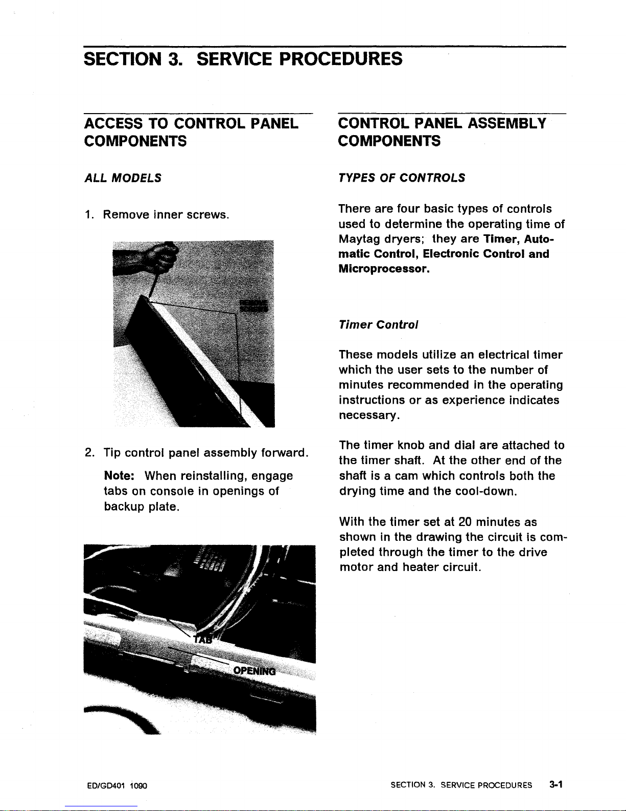
3.
SERVICE PROCEDURES
ACCESS TO CONTROL PANEL
COMPONENTS
ALL
MODELS
1.
Remove
inner
screws.
2.
Tip
control
panel
assembly
forward.
Note: When
reinstalling,
engage
tabs on console in openings
of
backup plate.
ED/GD401 1090
CONTROL PANEL ASSEMBLY
COMPONENTS
TYPES OF CONTROLS
There
are
four
basic
typesofcontrols
used to
determine
the
operating
time
of
May
tag
dryers;
they
are
Timer,
Auto-
matic
Control, Electronic Control and
Microprocessor.
Timer
Control
These
models
utilize
an electrical
timer
which
the
user
setstothe
number
of
minutes
recommendedinthe
operating
instructionsoras
experience
indicates
necessary.
The
timer
knob and
dial
are
attached to
the
timer
shaft.
At
the
other
endofthe
shaft is a cam
which
controls
both the
drying
time
and
the
cool-down.
With the
timer
set at 20 minutes as
shown in the
drawing
the
circuit
is com-
pleted
through
the
timertothe
drive
motor
and
heater
circuit.
SECTION3.SERVICE PROCEDURES
3-1
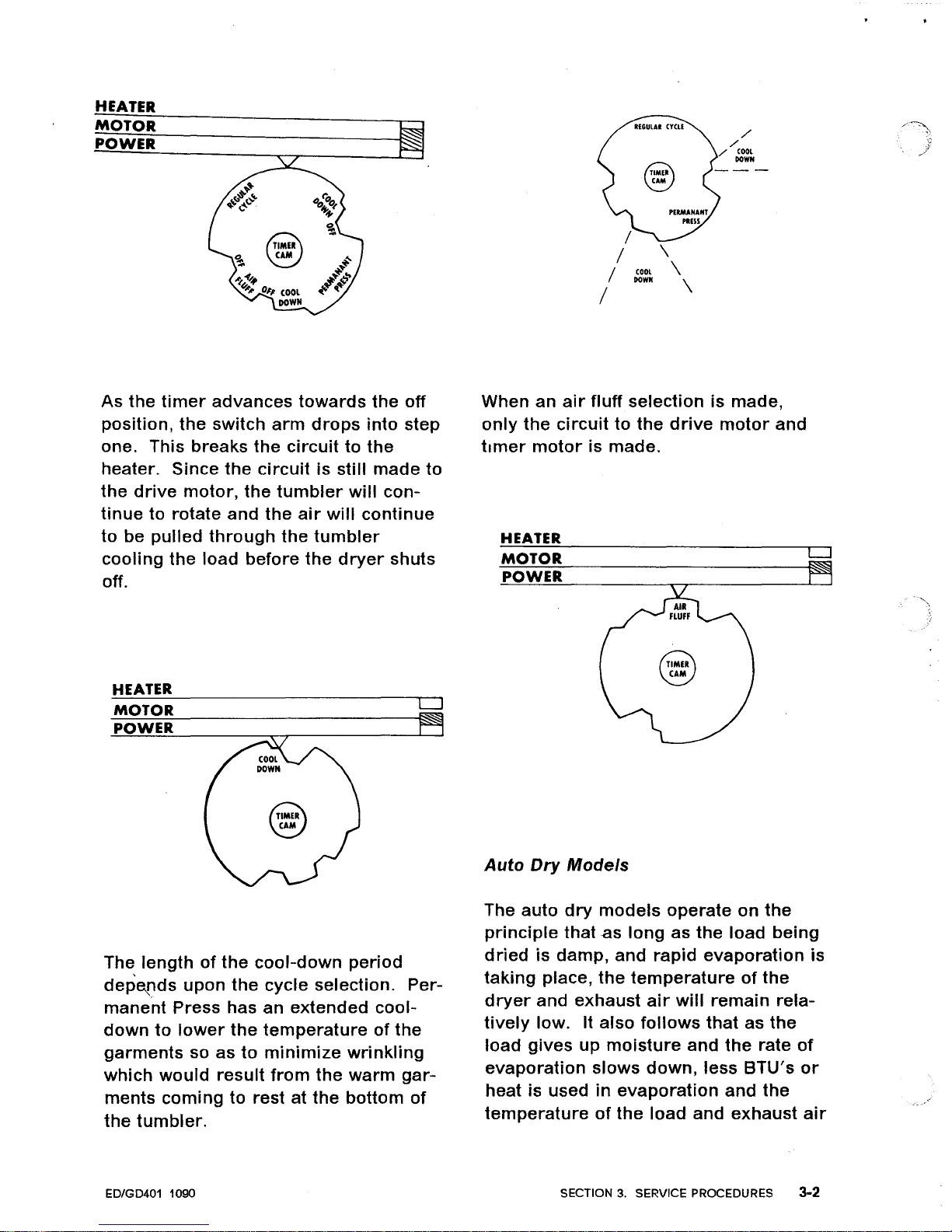
HEATER
MOTOR
POWER
~
~
/
./
./
coo,
GOWN
\
COOL
\
GOWN
\
As
the
timer
advances
towards
the
off
position,
the
switch
arm
drops
into
step
one. This breaks
the
circuittothe
heater. Since
the
circuitisstill
made
to
the
drive
motor,
the
tumbler
will
con-
tinue
to rotate
and
the
air
will
continue
to
be
pulled
through
the
tumbler
cooling
the
load
before
the
dryer
shuts
off.
HEATER
MOTOR
POWER
LJ
~
When an
air
fluff
selection is
made
,
only
the
circuittothe
drive
motor
and
timer
motor
is made.
HEATER
MOTOR
LJ
POWER
Auto
Dry
Models
The
lengthofthe
cool-down
period
depetlds
upon
the
cycle
selection. Per-
manent
Press has an
extended
cool-
downtolower
the
temperatureofthe
garments
so
astominimize
wrinkling
which
would
result
from
the
warm
gar-
ments
coming
to rest at
the
bottom
of
the
tumbler.
ED/GD401 1090
The auto
dry
models
operate
on
the
principle
that
as
long
as
the
load
being
driedisdamp,
and
rapid
evaporation
is
taking
place,
the
temperatureofthe
dryer
and
exhaust
air
will
remain
rela-
tively
low. It
also
follows
thatasthe
load
gives
up
moisture
and
the
rate
of
evaporation
slows
down,
less
BTU's
or
heat is usedinevaporation
and
the
temperatureofthe
load
and
exhaust
air
SECTION3.SERVICE PROCEDURES 3-2
 Loading...