


MAN GUIDE 106
The eTGE

The high-voltage components and the technologies used for the remaining subassemblies guarantee safe and comfortable mobility. The electric motor boasts a power output of 100 kW and develops a maximum torque of 290 Nm from a standstill. Depending on the vehicle payload, route and driving profile, the real range is approx. 120 km. According to the NEDC, the range is 173 km. In the new, more challenging WLTC, the range is 110 / 114 km. The nominal energy of the lithium-ion high-voltage battery is 35.8 kWh. The recuperation, i.e. the braking energy recovery, has been adapted for the eTGE with three-phase drive. Under certain circumstances, the three-phase current drive can cause a deceleration when in alternator mode. The power and control electronics for the electric drive supplies the energy generated to the high-voltage battery. With the eTGE, MAN is paving the way for sustainable, future-proof mobility.
m106_002
Attention! Dangerous electric voltage!
The eTGE is a battery-driven electric vehicle. It features a high-voltage system with a rated voltage of 323 volts. This voltage level can be fatal. Only qualified employees may perform work on this vehicle. The minimum qualification required is an electrically instructed person.
Technical status April 2019
2

Table of contents
4
8
4 |
Introduction |
6 |
Body |
8 |
Power transmission |
10 |
Heating and air conditioning |
16 |
Driver assist systems |
18 |
High-voltage system |
30 |
Electrical system |
38 |
Infotainment |
41 |
Service |
43 |
Test your knowledge |
|
|
|
18 |
|
38 |
|
|
|
The MAN TGE Guide teaches the basics of design and function for sales and after-sales of new vehicle models, new
vehicle components or new technologies. Note The MAN TGE Guide is not a sales manual nor a repair guide! Specified values are for the sake of easy understanding
only and refer to the data status valid at the time the MAN TGE Guide was created. The contents are not updated.
Please use the appropriate technical literature for customer advice, maintenance and repair work.
Reference
3

Introduction
The eTGE
The electric van is based on the TGE 2017. Like the versions with diesel engines, the new eTGE is also equipped with state-of-the-art assistance and comfort systems.
Because the battery is integrated in the underbody, the charging volume of the electric version with just under 10.7 m3 remains at the level of the conventional models with rear-wheel drive. The payload of the eTGE is approx. 1.0 tonne at a gross vehicle weight of 3.5 tonnes.
m106_004
4

The characteristic features of the eTGE
eTGE emblems in the front grille, on the side panels, in front of the wheel arches and at the rear left of the wing door at the height of the tail light
e-specific displays in MAN Media Van Advanced
Charging socket behind the tank cap
Instrument panel with e-specific displays
m106_005
5
Body
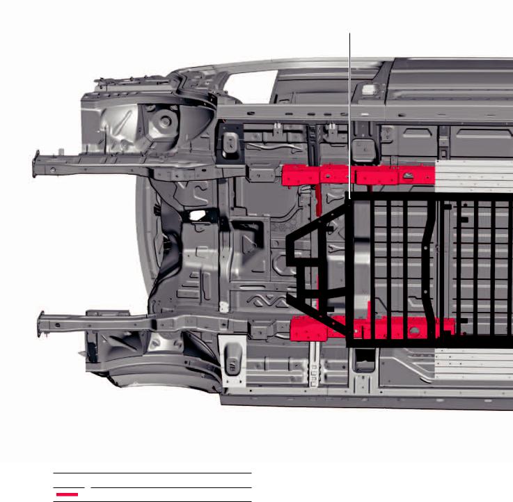
Body structure
The body structure is based on the vehicle body featured in the TGE 2017. In order to do justice to crash safety requirements, the necessary changes to
the geometry were implemented in the underbody, and additional components have been utilised.
Battery frame
Key
Body changes specifically for the eTGE
6
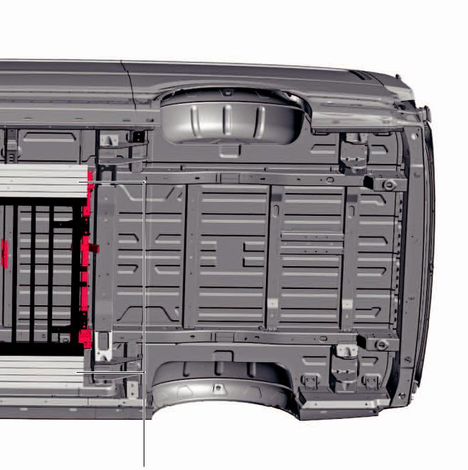
Underbody
The underbody has been extended, which allows installation of the high-voltage battery, also allowing the stricter impact requirements this involves to be satisfied . In the lateral areas, additional crash elements are installed between the high-voltage battery and the sill panels. A support frame is located under the middle
of the underbody, which serves as protection for the high-voltage battery from below. To protect against dirt, and to improve the drag coefficient, the front of the underbody features an underbody impact guard and there are 4 underbody covers in the middle.
m106_006
Crash elements
7
Power transmission
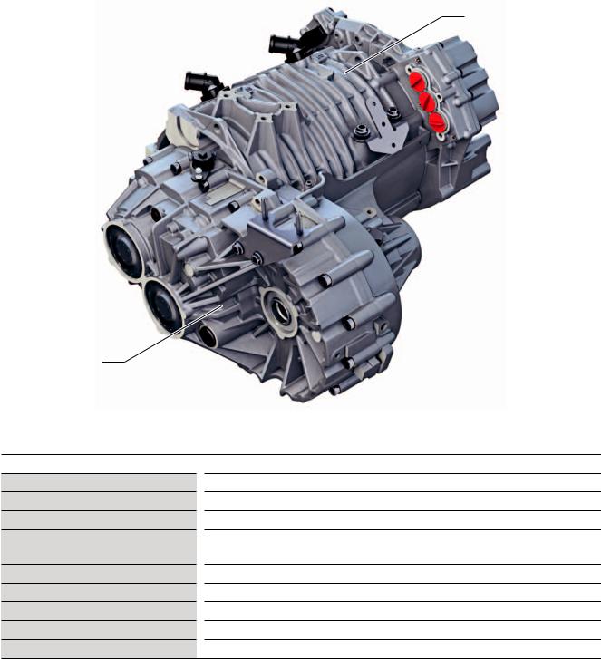
The 0MD 1-speed transmission
The 1-gear drive 0MD of the eTGE consists of proven components of the group. Thereby, all components, especially the lubrication in the gearbox, were optimally
designed to fulfil the high requirements in the commercial vehicles sector.
Three-phase current drive VX54
1-speed transmission 0MD
m106_007
Technical data
Transmission designation
Number of gears
Transmission stages
Transmission ratios
Max. input torque
Max. input speed
Weight (with oil)
Oil volume
Driveshafts
0MD
1
2
Level 1: 3.192 (Z1 = 26; Z2 = 83) Level 2: 3.609 (Z3 = 23; Z4 = 83)
290 Nm
12,000 rpm
32.2 kg
1.5 l
Splined connection
8

Oil supply system
Oil holes
The 1-speed gearbox 0MD of the eTGE uses splash lubrication. To ensure permanent lubrication, the final drive gear runs in the oil sump. This requires an appropriate design of the gearbox housing to ensure lubrication, cooling and oil distribution. Lubrication of the bearings for the drive shaft, drive shaft and axle drive is ensured on the gearbox and motor housing side by 2 transverse bores and grooves behind the bearing shells.
m106_009
Other necessary measures:
Reinforced tapered roller bearingsReinforced and larger parking lockReinforced toothing of the drive gearsReinforced differential
m106_008
Selector lever
The 1-gear gearbox 0MD and the selector lever E313 are connected by a cable. This mechanical connection is used only to activate the parking lock. The mechanical and electrical components of the selector lever are installed in the housing of the selector lever E313. The locking mechanism for the selector lever E313 is provided by the selector lever lock solenoid N110. In the event of a defect or a power failure, the selector lever E313 remains locked. The manual emergency release is located on the left of the selector mechanism. To unlock the selector lever lock, pull the locking lever backwards and press the selector lever lock button at the same time.
m106_010
9

Heating and air conditioning
Overview of components
A 2-zone Climatronic is installed as series standard. The interior air conditioning of the vehicle is carried out entirely with a heat pump system via the operating states “cooling” and “heating”. For cooling, the refrigerant circuit is switched on in the same way as for a normal air conditioning system. The system can switch from cooling to heating via the modified control of the expansion and shut-off valves. The hot refrigerant coming from the compressor is passed over
the heating condenser and gives off its heat there to the air flowing through, which heats the interior. The Climatronic control unit J255 controls and monitors the temperature sensors and the air and temperature flaps in the interior. The thermal management control unit J1024 controls, regulates and manages the expansion valves, shut-off valves, high voltage heating (PTC) Z115, electric air conditioning compressor and refrigerant pressure and temperature senders.
High-voltage heater (PTC) Z115
Electrical air conditioner compressor V470
10
The high-voltage heating (PTC) Z115 and the electric air conditioning compressor V470 operate on demand from the air conditioning control unit for heating/ cooling. The set temperature request is sent via CAN bus to the thermal management control unit J1024.
The e-Manager can be used to program the auxiliary air conditioning with three departure times (timer).
e-Manager
Climatronic control unit J255
m106_011
11

Heating and air conditioning
System overview
V470
G395
|
G829 |
|
N642 |
|
|
|
|
|
|
|
|
1 |
N643 |
|
|
|
|
|
|
|
|
|
|
|
|
|
N696 |
|
|
G827 |
|
|
|
N636 |
G826 |
|
|
|
|
3 |
|
2 |
|
|
|
|
|
|
|
|
|
4 |
|
|
|
|
|
5 |
|
G828 |
|
|
|
|
|
|
|
N637 |
|
N638 |
|
Refrigerant circuit |
|
6 |
|
|
|
|
|
|
|
|
|
Coolant circuit |
|
|
|
|
|
|
7 |
G110 |
|
|
|
|
|
|
|
|
|
|
|
Z115 |
|
G787 |
|
|
G785 |
V509 |
|
|
|
|
|
|
|
|
|
|
|
8 |
8 |
AX4 |
|
|
|
|
|
||
|
|
|
|
|
|
|
N632 |
|
|
|
VX54 |
|
|
|
|
|
|
|
G789 |
|
|
|
|
|
JX1 |
|
|
|
G788 |
|
|
|
|
|
|
|
V508 |
|
|
|
|
|
G83 |
|
|
|
|
9
10
m106_064
12

Key
AX4 |
|
Charging unit 1 for high-voltage battery |
|
|
|
G83 |
|
Radiator outlet coolant temperature |
|
|
sender |
|
|
|
G110 |
|
Air conditioning system coolant tempera- |
|
|
ture sender |
|
|
|
G395 |
|
Refrigerant pressure and temperature |
|
|
sender 1 |
|
|
|
G785 |
|
Temperature sender in the high-voltage |
|
|
heater (PTC) |
|
|
|
G787 |
|
Temperature sender after heat exchanger |
|
|
|
G788 |
|
Temperature sender after electric drive |
|
|
motor |
|
|
|
G789 |
|
Temperature sender after power and |
|
|
control electronics for electric drive |
|
|
|
G826 |
|
Refrigerant pressure and temperature |
|
|
sender 2 |
|
|
|
G827 |
|
Refrigerant pressure and temperature |
|
|
sender 3 |
|
|
|
G828 |
|
Refrigerant pressure and temperature |
|
|
sender 4 |
|
|
|
G829 |
|
Refrigerant pressure and temperature |
|
|
sender 5 |
|
|
|
JX1 |
|
Power and control electronics for electric |
|
|
drive |
|
|
|
N632 |
|
Coolant changeover valve 1 |
|
|
|
N636 |
|
Refrigerant expansion valve 1 |
|
|
|
N637 |
|
Refrigerant expansion valve 2 |
|
|
|
N638 |
|
Refrigerant expansion valve 3 |
|
|
|
N642 |
|
Refrigerant shut-off valve 4 |
|
|
|
N643 |
|
Refrigerant shut-off valve 5 |
|
|
|
N696 |
|
Refrigerant shut-off valve 1 |
|
|
|
V470 |
|
Electrical air conditioner compressor |
|
|
|
V508 |
|
Coolant circulation pump before power |
|
|
and control electronics for electric drive |
|
|
|
V509 |
|
Coolant circulation pump before high-vol- |
|
|
tage heater (PTC) |
|
|
|
VX54 |
|
Three-phase current drive |
|
|
|
Z115 |
|
The high-voltage heater (PTC) |
|
|
|
1
2
3
4
5
6
7
8
9
10
Dryer
Condenser
Evaporator
Temperature flap
Heat condenser
Heat exchanger for heat condenser
Internal temperature sender in the highvoltage heater (PTC)
Non-return valve
Thermostat
Cooler
Refrigerant circuit
Coolant circuit
13

Heating and air conditioning
Expansion valves and shut-off valves
The refrigerant circuit has three expansion valves and three shut-off valves.
Expansion valve
The expansion valves are designed as ball valves with a V-shaped control edge increasing in size. The expansion valves are actuated by the thermal management control unit J1024 as and when required. The electric valve is controlled so as to take any position between 0% (closed) and 100% (fully open). The expansion valves are all identical in design and are connected to the thermal management control unit via a LIN bus.
The refrigerant flows through the N637 (EXV2) in one direction or the other according to the function (heating or cooling).
m106_070
Coolant
The shut-off valves have been designed as ball valves. They are all identical in design and are connected to the thermal management control unit via a LIN bus. The valves can be 0% (closed) or 100% (fully open).
Note |
m106_071 |
|
When a valve is replaced, it must be readdressed via the |
||
|
||
diagnostic software in the thermal management control |
|
|
unit J1024. |
|
|
|
|
14
 Loading...