


 Loading...
Electrical System
TGS/TGX 06S-1580, 06S-1581 89S-0161, 89S-0162 26X-0150, 28X-0006, 30X-0273
Copy deadline: 03.2010
Wiring Diagrams
81.99298-6602 |
2nd edition |
K100 |
MAN Nutzfahrzeuge Aktiengesellschaft |
|
Schaltpläne K100, 2. Ausgabe |
Dachauer Str. 667 |
|
Elektrische Anlage |
80995 MÜNCHEN |
|
TGS/TGX |
oder |
|
- Englisch - |
Postfach 50 06 20 |
|
Printed in Germany |
80976 MÜNCHEN |
|
|
Wiring Diagrams K100
2nd edition
Electrical System
TGS/TGX 06S-1580, 06S-1581 89S-0161, 89S-0162
26X-0150, 28X-0006, 30X-0273
81.99298-6602

PREFACE/PRINTER'S IMPRINT
PREFACE
The"WiringDiagrams"manualdocumentstheentirescopeofseriesstandardandadditionalwiringdiagrams.
The series standard wiring diagrams and the additional wiring diagrams are illustrated with a detailed key and current path designations.
This manual is based on wiring diagrams created using CAD. This means the manual is quick and easy to update.
This manual describes the standard production version of your vehicle as at the copy deadline.
CAUTION
Type and source of danger
•Refers to working and operating procedures which must be followed exactly in order to avoid exposing people to risk.
WARNING
Type and source of danger
•Refers to working and operating procedures which must be followed exactly in order to avoid serious or irreparable damage to property.
Note
An explanatory note which is useful for understanding the working or operating procedure to be performed.
Comply with general safety regulations when performing any repair work.
Best wishes from
MAN Nutzfahrzeuge Aktiengesellschaft
Munich Plant
PRINTER’S IMPRINT
We reserve the right to make modi cations in the course of further development.
2010 MAN Nutzfahrzeuge Aktiengesellschaft
Reprinting, copying or translation, even of extracts, is not allowed without the written approval of MAN Nutzfahrzeuge AG.
All rights under the copyright law are strictly reserved by MAN Nutzfahrzeuge AG.
If any changes are made without the written approval of MAN Nutzfahrzeuge AG then MAN Nutzfahrzeuge AG shall not be liable for any warranty or guarantee claims arising from damage and defects attributable to the unauthorised modi cation. Furthermore, MAN Nutzfahrzeuge AG shall not be liable for any damage resulting from the unapproved modi cation.
Redaktion: SAWET-Y / HA 03.2010
Satz: SAWET-Y
Druck: MAN-Werksdruckerei
2 |
K100 2nd edition |
TABLE OF CONTENTS |
||
Content |
Chapter/Page |
|
Index |
|
7 |
Abbreviations |
|
9 |
Introduction |
|
|
Safety instructions ....................................................................................................... |
|
15 |
Overview of models ..................................................................................................... |
|
20 |
Explanatory notes to the wiring diagrams ........................................................................... |
|
23 |
Series standard wiring diagram |
|
|
wiring diagram No. 81.99192.3079 .................................................................................. |
|
26 |
A = Voltage supply, starting system.................................................... |
sheet 1 of 22.......... |
26 |
A = On-board computer voltage supply / B = EBS voltage supply / C = Vehicle |
|
|
management computer voltage supply................................................ |
sheet 2 of 22.......... |
28 |
A = Chassis earth distributor............................................................ |
sheet 3 of 22.......... |
30 |
A = On-board diagnosis (OBD) diagnosis socket / B = ZDR interface (FFR) |
|
|
(MDB, HGB)................................................................................ |
sheet 4 of 22.......... |
32 |
A = Flame start system / B = Fan clutch / C = EDC coolant temperature / D = |
|
|
Coolant level / E = Air lter pressure sensor / F = Power steering oil level..... |
sheet 5 of 22.......... |
34 |
A = Probe for clutch uid level / B = Multifunctional steering wheel / C = |
|
|
Steering column stalk / D = Sustained-action brake / E = Distributor, line |
|
|
60028........................................................................................ |
sheet 6 of 22.......... |
36 |
A = Air dryer/brake circuit monitoring / B = Cab lock check / C = Fuel gauge .sheet 7 of 22.......... |
38 |
|
A = Signal horn / B = Fuel lter heater preparation / C = Engine brake / D = |
|
|
Oil level sensor / E = M-CAN / F = Outside temperature .......................... |
sheet 8 of 22.......... |
40 |
A = Heater blower/air-conditioning system........................................... |
sheet 9 of 22.......... |
42 |
A = Washers and wipers................................................................. |
sheet 10 of 22........ |
44 |
A = Immobiliser / B = Gear selector lever / C = Vehicle management computer |
|
|
diagnosis / D = Accelerator pedal unit................................................. |
sheet 11 of 22 ........ |
46 |
A = Voltage supply +15 / B = Instrumentation/tachograph ........................ |
sheet 12 of 22........ |
48 |
A = Lighting learning routine / B = Light circuit / C = Fog lamp/rear fog lamp |
|
|
circuit / D = Cigarette lighter / E = Ashtray lighting.................................. |
sheet 13 of 22........ |
50 |
A = Parking lights, left / B = Parking lights, right..................................... |
sheet 14 of 22........ |
52 |
A = Headlight ash / B = Headlight low beam, headlight high beam, daytime |
|
|
driving lights / C = Headlight beam regulator ........................................ |
sheet 15 of 22........ |
54 |
A = Rear fog lamps / B = Fog lamps, additional high beam headlights, |
|
|
cornering light, left / C = Fog lamps, additional high beam headlights, |
|
|
cornering light, right....................................................................... |
sheet 16 of 22........ |
56 |
A = Brake light / B = Parking brake / C = Reversing light.......................... |
sheet 17 of 22........ |
58 |
A = Pushbutton unit illumination / B = Permanent load voltage supply / C = |
|
|
Entrance lighting / D = Interior lights................................................... |
sheet 18 of 22........ |
60 |
A = Turn indicators........................................................................ |
sheet 19 of 22........ |
62 |
A = Spare lines / B = Spare lines for trailer socket / C = Spare lines for engine |
|
|
start/stop.................................................................................... |
sheet 20 of 22........ |
64 |
A = Gearbox / B = T-CAN network..................................................... |
sheet 21 of 22........ |
66 |
A = Intarder, retarder / B = Power take-off............................................ |
sheet 22 of 22........ |
68 |
Additional wiring diagrams |
|
|
wiring diagram No. 81.99192.2496 .................................................................................. |
|
72 |
Trailer socket 24V 7-pole ................................................................ |
sheet 1 of 1 ........... |
72 |
wiring diagram No. 81.99192.2498 .................................................................................. |
|
74 |
Trailer socket 24V 7-pole/7-pole ....................................................... |
sheet 1 of 1 ........... |
74 |
wiring diagram No. 81.99192.1358 .................................................................................. |
|
76 |
ASR check lamp........................................................................... |
sheet 1 of 1 ........... |
76 |
wiring diagram No. 81.99192.3222 .................................................................................. |
|
78 |
K100 2nd edition |
|
3 |

TABLE OF CONTENTS
ASR slip thresholds button .............................................................. |
sheet 1 of 1 |
........... 78 |
wiring diagram No. 81.99192.2495 .................................................................................. |
|
80 |
Battery master switch, mechanical..................................................... |
sheet 1 of 1 ........... |
80 |
wiring diagram No. 81.99192.3235 .................................................................................. |
|
82 |
Interaxle and transverse differential lock, rear axle (3-axle vehicle)............. |
sheet 1 of 1 ........... |
82 |
wiring diagram No. 81.99192.3233 .................................................................................. |
|
84 |
Transverse differential lock, rear axle (2-axle vehicle) ............................. |
sheet 1 of 1 ........... |
84 |
wiring diagram No. 81.99192.3246 .................................................................................. |
|
86 |
Electronic Brake System EBS 5 (2-axle vehicle).................................... |
sheet 1 of 3 ........... |
86 |
Electronic Brake System EBS 5 (2-axle vehicle).................................... |
sheet 2 of 3 ........... |
88 |
Electronic Brake System EBS 5 (2-axle vehicle).................................... |
sheet 3 of 3 ........... |
90 |
wiring diagram No. 81.99192.3247 .................................................................................. |
|
92 |
Electronic Brake System EBS 5 (3-axle vehicle).................................... |
sheet 1 of 4 ........... |
92 |
Electronic Brake System EBS 5 (3-axle vehicle).................................... |
sheet 2 of 4 ........... |
94 |
Electronic Brake System EBS 5 (3-axle vehicle).................................... |
sheet 3 of 4 ........... |
96 |
Electronic Brake System EBS 5 (3-axle vehicle).................................... |
sheet 4 of 4 ........... |
98 |
wiring diagram No. 81.99192.3250 ................................................................................ |
|
100 |
ECAS 2 (4x2) .............................................................................. |
sheet 1 of 2 .......... |
100 |
ECAS 2 (4x2) .............................................................................. |
sheet 2 of 2 .......... |
102 |
wiring diagram No. 81.99192.3248 ................................................................................ |
|
104 |
ECAS 2 (4x2 - semitrailer)............................................................... |
sheet 1 of 2 .......... |
104 |
ECAS 2 (4x2 - semitrailer)............................................................... |
sheet 2 of 2 .......... |
106 |
wiring diagram No. 81.99192.3253 ................................................................................ |
|
108 |
ECAS 2 (6x2 optionally with ALM/crane) ............................................. |
sheet 1 of 2 .......... |
108 |
ECAS 2 (6x2 optionally with ALM/crane) ............................................. |
sheet 2 of 2 .......... |
110 |
wiring diagram No. 81.99192.3624 ................................................................................ |
|
112 |
EDC7 Euro 3 D20... ...................................................................... |
sheet 1 of 3 .......... |
112 |
EDC7 Euro 3 D20... ...................................................................... |
sheet 2 of 3 .......... |
114 |
EDC7 Euro 3 D20... ...................................................................... |
sheet 3 of 3 .......... |
116 |
wiring diagram No. 81.99192.3625 ................................................................................ |
|
118 |
EDC7 Common Rail Euro 3 D2676 LF, E-EGR ..................................... |
sheet 1 of 4 .......... |
118 |
EDC7 Common Rail Euro 3 D2676 LF, E-EGR ..................................... |
sheet 2 of 4 .......... |
120 |
EDC7 Common Rail Euro 3 D2676 LF, E-EGR ..................................... |
sheet 3 of 4 .......... |
122 |
EDC7 Common Rail Euro 3 D2676 LF, E-EGR ..................................... |
sheet 4 of 4 .......... |
124 |
wiring diagram No. 81.99192.3617 ................................................................................ |
|
126 |
Electric cab tilt mechanism.............................................................. |
sheet 1 of 1 .......... |
126 |
wiring diagram No. 81.99192.3260 ................................................................................ |
|
128 |
EVB, controlled............................................................................ |
sheet 1 of 1 .......... |
128 |
wiring diagram No. 81.99192.3173 ................................................................................ |
|
130 |
Cab, T-CAN, standard.................................................................... |
sheet 1 of 1 .......... |
130 |
wiring diagram No. 81.99192.3267 ................................................................................ |
|
132 |
Window lifter, button in shift console .................................................. |
sheet 1 of 1 .......... |
132 |
wiring diagram No. 81.99192.3276 ................................................................................ |
|
134 |
Gearbox / manual gearbox.............................................................. |
sheet 1 of 2 .......... |
134 |
Gearbox / manual gearbox.............................................................. |
sheet 2 of 2 .......... |
136 |
wiring diagram No. 81.99192.3748 ................................................................................ |
|
138 |
Gearbox / manual gearbox.............................................................. |
sheet 1 of 2 .......... |
138 |
Gearbox / manual gearbox.............................................................. |
sheet 2 of 2 .......... |
140 |
wiring diagram No. 81.99192.1374 ................................................................................ |
|
142 |
Seat belt indicator, driver ................................................................ |
sheet 1 of 1 .......... |
142 |
wiring diagram No. 81.99192.3292 ................................................................................ |
|
144 |
Trailer charge, 24V........................................................................ |
sheet 1 of 1 .......... |
144 |
wiring diagram No. 81.99192.3237 ................................................................................ |
|
146 |
I-CAN cab (standard)..................................................................... |
sheet 1 of 1 .......... |
146 |
wiring diagram No. 81.99192.3405 ................................................................................ |
|
148 |
I-CAN roof (standard) .................................................................... |
sheet 1 of 1 .......... |
148 |
wiring diagram No. 81.99192.3293 ................................................................................ |
|
150 |
Interior lighting, roof, white/red ......................................................... |
sheet 1 of 1 .......... |
150 |
wiring diagram No. 81.99192.3461 ................................................................................ |
|
152 |
Interior lights with ambient light......................................................... |
sheet 1 of 1 .......... |
152 |
wiring diagram No. 81.99192.3295 ................................................................................ |
|
154 |
4 |
K100 2nd edition |

|
TABLE OF CONTENTS |
|
Intarder ..................................................................................... |
sheet 1 of 1 .......... |
154 |
wiring diagram No. 81.99192.3043 ................................................................................ |
|
156 |
Tachograph check lamp.................................................................. |
sheet 1 of 1 .......... |
156 |
wiring diagram No. 81.99192.3304 ................................................................................ |
|
158 |
Fuel lter heater........................................................................... |
sheet 1 of 1 .......... |
158 |
wiring diagram No. 81.99192.3305 ................................................................................ |
|
160 |
Fuel lter heater, Separ.................................................................. |
sheet 1 of 1 .......... |
160 |
wiring diagram No. 81.99192.3300 ................................................................................ |
|
162 |
Customer-speci c control module (KSM)............................................. |
sheet 1 of 2 .......... |
162 |
Customer-speci c control module (KSM)............................................. |
sheet 2 of 2 .......... |
164 |
wiring diagram No. 81.99192.3314 ................................................................................ |
|
166 |
Headlight beam regulator................................................................ |
sheet 1 of 1 .......... |
166 |
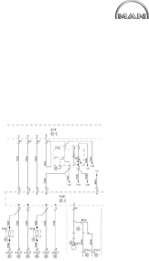
wiring diagram No. 81.99192.3120 ................................................................................ |
|
168 |
Fan clutch with speed feedback........................................................ |
sheet 1 of 1 .......... |
168 |
wiring diagram No. 81.99192.1656 ................................................................................ |
|
170 |
Engine brake............................................................................... |
sheet 1 of 1 .......... |
170 |
wiring diagram No. 81.99192.3316 ................................................................................ |
|
172 |
Engine brake, automatic, off ............................................................ |
sheet 1 of 1 .......... |
172 |
wiring diagram No. 81.99192.3501 ................................................................................ |
|
174 |
Multifunctional steering wheel .......................................................... |
sheet 1 of 1 .......... |
174 |
wiring diagram No. 81.99192.3366 ................................................................................ |
|
176 |
Fog lamps/additional high beam headlights and cornering light.................. |
sheet 1 of 1 .......... |
176 |
wiring diagram No. 81.99192.3337 ................................................................................ |
|
178 |
Pritarder/Intarder, automatic, off........................................................ |
sheet 1 of 1 .......... |
178 |
wiring diagram No. 81.99192.3134 ................................................................................ |
|
180 |
Basicline radio............................................................................. |
sheet 1 of 1 .......... |
180 |
wiring diagram No. 81.99192.3490 ................................................................................ |
|
182 |
Topline radio ............................................................................... |
sheet 1 of 2 .......... |
182 |
Topline radio ............................................................................... |
sheet 2 of 2 .......... |
184 |
wiring diagram No. 81.99192.3349 ................................................................................ |
|
186 |
Bunk light, bottom......................................................................... |
sheet 1 of 1 .......... |
186 |
wiring diagram No. 81.99192.2592 ................................................................................ |
|
188 |
Side marker lights......................................................................... |
sheet 1 of 1 .......... |
188 |
wiring diagram No. 81.99192.3298 ................................................................................ |
|
190 |
Seat heating, driver....................................................................... |
sheet 1 of 1 .......... |
190 |
wiring diagram No. 81.99192.3313 ................................................................................ |
|
192 |
Voltage transformer, 12V ................................................................ |
sheet 1 of 1 .......... |
192 |
wiring diagram No. 81.99192.3317 ................................................................................ |
|
194 |
START/STOP device on engine........................................................ |
sheet 1 of 1 .......... |
194 |
wiring diagram No. 81.99192.3395 ................................................................................ |
|
196 |
Storage locker lighting, rear left ........................................................ |
sheet 1 of 1 .......... |
196 |
wiring diagram No. 81.99192.3396 ................................................................................ |
|
198 |
Storage locker lighting, rear right....................................................... |
sheet 1 of 1 .......... |
198 |
wiring diagram No. 81.99192.3350 ................................................................................ |
|
200 |
Storage locker lighting, top (left, middle).............................................. |
sheet 1 of 1 .......... |
200 |
wiring diagram No. 81.99192.3351 ................................................................................ |
|
202 |
Storage locker lighting, top (left, middle, right)....................................... |
sheet 1 of 1 .......... |
202 |
wiring diagram No. 81.99192.3367 ................................................................................ |
|
204 |
Sockets in cab, 12V and 24V ........................................................... |
sheet 1 of 1 .......... |
204 |
wiring diagram No. 81.99192.3082 ................................................................................ |
|
206 |
Anti-jackknife brake for EBS5........................................................... |
sheet 1 of 1 .......... |
206 |
wiring diagram No. 81.99192.3221 ................................................................................ |
|
208 |
T-CAN terminating resistor in cab...................................................... |
sheet 1 of 1 .......... |
208 |
wiring diagram No. 81.99192.3174 ................................................................................ |
|
210 |
T-CAN standard/ECAS................................................................... |
sheet 1 of 1 .......... |
210 |
wiring diagram No. 81.99192.3175 ................................................................................ |
|
212 |
T-CAN standard/ECAS/Intarder ........................................................ |
sheet 1 of 1 .......... |
212 |
wiring diagram No. 81.99192.3178 ................................................................................ |
|
214 |
T-CAN standard/Intarder................................................................. |
sheet 1 of 1 .......... |
214 |
wiring diagram No. 81.99192.3180 ................................................................................ |
|
216 |
T-CAN (KSM) .............................................................................. |
sheet 1 of 1 .......... |
216 |
K100 2nd edition |
5 |

TABLE OF CONTENTS
wiring diagram No. 81.99192.3077 ................................................................................ |
|
218 |
Door module ............................................................................... |
sheet 1 of 5 .......... |
218 |
Door module ............................................................................... |
sheet 2 of 5 .......... |
220 |
Door module ............................................................................... |
sheet 3 of 5 .......... |
222 |
Door module ............................................................................... |
sheet 4 of 5 .......... |
224 |
Door module ............................................................................... |
sheet 5 of 5 .......... |
226 |
wiring diagram No. 81.99192.3303 ................................................................................ |
|
228 |
Preparation, transverse differential lock, rear axle (2-axle vehicle).............. |
sheet 1 of 1 .......... |
228 |
wiring diagram No. 81.99192.3379 ................................................................................ |
|
230 |
Preparation, central lubrication system ............................................... |
sheet 1 of 1 .......... |
230 |
wiring diagram No. 81.99192.3352 ................................................................................ |
|
232 |
Central lubrication system............................................................... |
sheet 1 of 1 .......... |
232 |
6 |
K100 2nd edition |
|
INDEX |
Catchword |
Page |
Numeric/Symbols |
|
81.99192.1358............................................................................................................................................... |
76 |
81.99192.1374............................................................................................................................................. |
142 |
81.99192.1656............................................................................................................................................. |
170 |
81.99192.2495............................................................................................................................................... |
80 |
81.99192.2496............................................................................................................................................... |
72 |
81.99192.2498............................................................................................................................................... |
74 |
81.99192.2592............................................................................................................................................. |
188 |
81.99192.3043............................................................................................................................................. |
156 |
81.99192.3077............................................................................................................................................. |
218 |
81.99192.3079............................................................................................................................................... |
26 |
81.99192.3082............................................................................................................................................. |
206 |
81.99192.3120............................................................................................................................................. |
168 |
81.99192.3134............................................................................................................................................. |
180 |
81.99192.3173............................................................................................................................................. |
130 |
81.99192.3174............................................................................................................................................. |
210 |
81.99192.3175............................................................................................................................................. |
212 |
81.99192.3178............................................................................................................................................. |
214 |
81.99192.3180............................................................................................................................................. |
216 |
81.99192.3221............................................................................................................................................. |
208 |
81.99192.3222............................................................................................................................................... |
78 |
81.99192.3233............................................................................................................................................... |
84 |
81.99192.3235............................................................................................................................................... |
82 |
81.99192.3237............................................................................................................................................. |
146 |
81.99192.3246............................................................................................................................................... |
86 |
81.99192.3247............................................................................................................................................... |
92 |
81.99192.3248............................................................................................................................................. |
104 |
81.99192.3250............................................................................................................................................. |
100 |
81.99192.3253............................................................................................................................................. |
108 |
81.99192.3260............................................................................................................................................. |
128 |
81.99192.3267............................................................................................................................................. |
132 |
81.99192.3276............................................................................................................................................. |
134 |
81.99192.3292............................................................................................................................................. |
144 |
81.99192.3293............................................................................................................................................. |
150 |
81.99192.3295............................................................................................................................................. |
154 |
81.99192.3298............................................................................................................................................. |
190 |
81.99192.3300............................................................................................................................................. |
162 |
81.99192.3303............................................................................................................................................. |
228 |
81.99192.3304............................................................................................................................................. |
158 |
81.99192.3305............................................................................................................................................. |
160 |
81.99192.3313............................................................................................................................................. |
192 |
81.99192.3314............................................................................................................................................. |
166 |
81.99192.3316............................................................................................................................................. |
172 |
81.99192.3317............................................................................................................................................. |
194 |
81.99192.3337............................................................................................................................................. |
178 |
81.99192.3349............................................................................................................................................. |
186 |
81.99192.3350............................................................................................................................................. |
200 |
81.99192.3351............................................................................................................................................. |
202 |
81.99192.3352............................................................................................................................................. |
232 |
81.99192.3366............................................................................................................................................. |
176 |
81.99192.3367............................................................................................................................................. |
204 |
81.99192.3379............................................................................................................................................. |
230 |
81.99192.3395............................................................................................................................................. |
196 |
81.99192.3396............................................................................................................................................. |
198 |
81.99192.3405............................................................................................................................................. |
148 |
81.99192.3461............................................................................................................................................. |
152 |
81.99192.3490............................................................................................................................................. |
182 |
81.99192.3501............................................................................................................................................. |
174 |
81.99192.3617............................................................................................................................................. |
126 |
K100 2nd edition |
7 |

INDEX
81.99192.3624............................................................................................................................................. |
112 |
81.99192.3625............................................................................................................................................. |
118 |
81.99192.3748............................................................................................................................................. |
138 |
8 |
K100 2nd edition |
LIST OF ABBREVIATIONS
Abbreviations |
|
|
A |
|
|
a |
Acceleration |
|
ABE |
General certi cation |
|
ABS |
Anti-lock Braking System |
|
ABV |
Anti-skid system |
|
AC |
Air Conditioning |
|
ACC |
Adaptive Cruise Control |
|
ACK |
Acknowledge |
|
ADC |
Analogue-Digital Converter |
|
ADR |
European agreement for cross-border transport of dangerous goods by road (French title: Accord |
|
|
européen relatif au transport international des marchandises Dangereuses par Route) |
|
AGB |
Automatic road speed limiter |
|
AGND |
Analogue Ground |
|
AGR |
Exhaust gas recirculation |
|
AHK |
Trailer coupling |
|
AHV |
Trailer brake valve |
|
ALB |
Automatic load balancing |
|
ALM |
Axle Load Monitoring |
|
AMA |
Antenna mast system |
|
AMR |
Anisotropic Magneto-Resistance |
|
ANH |
Trailer / semitrailer |
|
AS |
Automatic gearbox |
|
ASD |
Trailer socket |
|
ASM |
Trailer control module |
|
ASR |
Anti-spin regulator (traction control) |
|
ASV |
Trailer control valve |
|
ATC |
Automatic Temperature Control |
|
ATF |
Automatic Transmission Fluid |
|
AU |
Statutory exhaust emission test |
|
AV |
Exhaust valve |
|
AVS |
Automatic gear preselection |
|
B |
|
|
BA |
Operator's manual |
|
BBA |
Service brake system |
|
BBV |
Service brake valve |
|
BITE |
Built-in test equipment |
|
BKR |
Brake power regulator |
|
BUGH |
Front heater |
|
BV |
Backup valve |
|
BVA |
Brake wear indicator |
|
BVS |
Brake wear sensor |
|
BVV |
Brake wear sensor supply |
|
BW |
German Army |
|
BWG |
Brake power sensor |
|
BZ |
Brake cylinder |
|
C |
|
|
CAN |
Controller Area Network (data bus system with serial bit transmission) |
|
CAN-H |
CAN-high data line |
|
CAN-L |
CAN-low data line |
|
CATS |
Computer-assisted testing and diagnostic system |
|
CBU |
Central Brake Unit |
|
CDC |
Continuous Damping Control |
|
CCVS |
Cruise control vehicle speed |
|
CKD |
Completely Knocked Down |
|
CNG |
Compressed Natural Gas |
|
CPU |
Central Processing Unit |
|
CRT |
Continuously Regenerating Trap (exhaust muf er, two-way catalytic converter, diesel particulate |
|
|
lter) |
|
|
K100 2nd edition |
9 |

LIST OF ABBREVIATIONS
CRC |
Cyclic Redundancy Check |
CS |
Comfort Shift |
D |
|
DAHL |
Roof ventilator |
DBR |
Sustained-action brake relay |
DCU |
Dosing Control Unit (AdBlue dosing) |
DF |
Speed sensor |
DFÜ |
Data transmission |
DIA |
Diagnosis and information display |
DIAG |
Diagnosis, entire vehicle |
DIAG - |
Diagnosis, entire vehicle – Multiplex central computer (buses only) |
MUX |
|
DIAK |
Diagnosis, K-line (data line) |
DIAL |
Diagnosis, L-line (interrogation line) |
DIAR |
Diagnosis, further interrogation |
DIN |
German industrial standard |
DKE |
Throttle valve increase (ASR control) |
DKH |
Roof duct heating |
DKL |
Roof aps |
DKR |
Throttle valve reduction (reduction request from ASR to EDC / EMS) |
DKV |
Throttle valve speci cation (load sensor signal from pedal value sensor, EDC / EMS) |
DLB |
Compressed air brake system |
DM |
Diagnostic Message |
DNR |
Drive Neutral Reverse (selector lever switch for automatic) |
DPF |
Diesel Particulate Filter |
DRM |
Pressure control module |
DRS |
Rotational speed sensor |
DS |
Pressure sensor |
DSV |
Pressure control valve |
DTC |
Diagnostic Trouble Code (OBD fault code) |
DTCO |
Digital tachograph |
DV |
Throttle valve |
DWA |
Anti-theft warning system |
DZG |
Speed sensor |
DZM |
Rev counter |
E |
|
EBS |
Electronic Brake System |
ECAM |
Electronically Controlled Air Management |
ECAS |
Electronically Controlled Air Suspension |
ECE |
Emergency shut-off to ECE 36 |
ECU |
Electronic Control Unit |
EDC |
Electronic Diesel Control |
EDC S |
Electronic Diesel Control Slave |
EDM |
Electronic diesel consumption meter |
EDR |
Maximum speed governor |
EEC |
Electronic engine controller |
EEPROM |
Electrically erasable and programmable read-only memory |
EFR |
Electronic shock absorber control (ESAC) |
EFS |
Electric driver's seat |
EHAB |
Electro-hydraulic shut-off device |
ELAB |
Electrical shut-off device |
ELF |
Electronically controlled air suspension |
EMS |
Electronic throttle control (ETC) |
EMV |
Electromagnetic compatibility (EMC) |
EOL |
End-of-line (programming) |
EP |
Injection pump |
ER |
Engine retarder (engine brake) |
ESAC |
Electronic Shock Absorber Control |
ESP |
Electronic Stability Program |
10 |
K100 2nd edition |

LIST OF ABBREVIATIONS
ESR |
Electric sun-blind |
EST |
Electronic control unit |
EV |
Intake valve |
EVB |
Exhaust Valve Brake |
F |
|
FAP |
Driver's area |
FAQ |
Frequently Asked Questions |
FBA |
Parking brake system |
FBM |
Pedal brake module |
FDR |
Dynamic handling control |
FDF |
Vehicle data le |
FFR |
Vehicle management computer |
FGB |
Road speed limiter (RSL) |
FGR |
Road speed governor (RSG) |
FHS |
Cab |
FIN |
Vehicle identi cation number (17 digits) |
FM |
Vehicle management |
FMI |
Failure Mode Identi cation |
FMS |
Fleet Management Standard (global telematics standard) |
FMR |
Vehicle/engine management |
FOC |
Front Omnibus Chassis (bus/coach chassis with front-mounted engine) |
FSCH |
Windscreen heater |
FSG |
Ground reinforcement system |
FSH |
Window/mirror heating |
FTW |
Driver's partition |
FUNK |
Radio communication unit |
FZA |
Destination system |
FZNR |
Vehicle number (7 digits) |
G |
|
GDK |
Controlled diesel catalytic converter |
GEN |
Alternator |
GET |
Gearbox |
GGVS |
Europeanagreementforcross-bordertransportofdangerousgoodsbyroad(Frenchabbreviation: |
|
ADR) |
GND |
Ground |
GP |
Gearbox planetary gear group (range-change box) |
GS |
Gearbox control |
GV |
Gearbox splitter gear group (splitter box) |
H |
|
HA |
Rear axle |
HBA |
Auxiliary brake system |
HD-OBD |
Heavy Duty On-Board Diagnosis |
HDS |
Urea dosing system |
HGB |
Maximum road speed limiter |
HGS |
Hydraulic gearshift |
HLUE |
Hydrostatic fan |
HOC |
Rear Omnibus Chassis (bus/coach chassis with rear-mounted engine) |
HSS |
Highside switch |
HST |
Main switch panel |
HU |
Main inspection |
HYD |
Hydronic auxiliary heater |
HYDRIVE Hydrostatic front-wheel drive |
|
HYDRO |
MAN Hydro Drive |
HVA |
Hydrostatic front-wheel drive |
Hz |
Hertz (number of cycles per second) |
HZA |
Bus stop indicator system |
HZG |
Auxiliary speed sensor |
K100 2nd edition |
11 |

LIST OF ABBREVIATIONS
I |
|
IBEL |
Interior lighting |
IBIS |
Integrated on-board information system |
IC |
Integrated Circuit |
ID |
Identi cation |
IMR |
Integrated Mechanical Relay (starter control) |
INA |
Information lamp (e.g. check lamp) |
INST |
Instrumentation |
IR |
Individual control (ABS) |
IRM |
Modi ed individual control (ABS) |
ISO |
International Standards Organisation |
IWZ |
Incremental angle/time measuring system |
K |
|
KBZ |
Combination brake cylinder |
KFH |
Fuel lter heater |
KITAS |
Kienzle intelligent tachograph sensor |
KLI |
Air-conditioning system |
KNEEL |
Kneeling |
KSM |
Customer-speci ed control module (control unit for external data exchange) |
KSW |
Customer's special request |
KWP |
Key Word Protocol (protocol for MAN-cats diagnosis) |
L |
|
LBH |
Air reservoir |
LCD |
Liquid Crystal Display |
LDA |
Manifold-pressure compensator (boost control) |
LDF |
Boost pressure sensor |
LDS |
Air spring/damper system |
LED |
Light emitting diode |
LF |
Air suspension |
LGS |
Lane Guard System |
LL |
Idling speed |
LLA |
Idling speed increase |
LLR |
Idling speed control |
LNA |
Steering trailing axle |
LNG |
Lique ed Natural Gas |
LOE |
Steering oil monitor |
LPG |
Lique ed Petroleum Gas |
LSVA |
Distance-based heavy vehicle toll |
LWR |
Headlight beam regulator |
LWS |
Steering angle sensor |
M |
|
M-TCO |
Modular EU tachograph |
MAB |
Solenoid valve shut-off (engine shut-off by high-pressure solenoid valve in injection pump) |
MANcatsMAN computer-assisted testing and diagnostic system |
|
MAR |
Solenoid valve shut-off relay (redundant engine shut-off relay) |
MDB |
Engine speed range |
MES |
Quantity positioner |
MFL |
Multifunctional steering wheel |
ML |
Midline |
MMI |
Man-machine interface |
MOTB |
Engine brake |
MP |
Motor power box (cable duct on engine block) |
MR |
Engine governor - ASR |
MSG |
Engine control unit (EDC) |
MUX |
Multiplex central computer (bus only) |
MV |
Solenoid valve |
MZ |
Diaphragm cylinder |
12 |
K100 2nd edition |

LIST OF ABBREVIATIONS
N |
|
|
n |
Speed (rpm) |
|
NA |
Power take-off |
|
NBF |
Needle movement sensor |
|
NES |
New Electronic Structure |
|
NFZ |
Commercial vehicles |
|
NLA |
Trailing axle |
|
NSL |
Rear fog lamp |
|
NSW |
Fog lamps |
|
O |
|
|
OBD |
On-Board Diagnosis |
|
OBDU |
Onboard Diagnostic Unit (subsystem of central on-board computer) |
|
OC |
Occurrence Count (frequency counter of an error) |
|
OEAB |
Oil separator |
|
OENF |
Oil top-up |
|
P |
|
|
p |
Pressure |
|
PBM |
Pulse Breadth Modulation (also see PWM) |
|
P-Code |
Powertrain code (power pack/powertrain fault code) |
|
Particulate Diesel Filter |
|
|
PLM |
Programmable Logic Module |
|
PM-Kat |
Particulate matter catalytic converter (particulate catalytic converter) |
|
PSG |
Pump control unit (EDC) |
|
PTM |
Powertrain Manager (replacement for vehicle management computer) |
|
PTO |
Power Take-Off |
|
PWG |
Pedal value sensor |
|
PWM |
Pulse Width Modulation (also see PBM) |
|
R |
|
|
RA |
Repair manual |
|
RAH |
Interior heating |
|
RAM |
Random Access Memory |
|
RAS |
Rear Axle Steering |
|
RAS-EC |
Rear Axle Steering with Electronic Control |
|
RDRA |
Tyre pressure control system |
|
RDS |
Radio Data System |
|
RET |
Retarder |
|
RET P |
Primary retarder |
|
RET S |
Secondary retarder |
|
RKL |
Priority vehicle light |
|
RKS |
Tyre pressure monitor |
|
RLV |
Relay valve |
|
RME |
Rape seed oil methyl ester (biodiesel) |
|
ROM |
Read Only Memory |
|
S |
|
|
SA |
Special equipment |
|
SAE |
Society of Automotive Engineers |
|
SAMT |
Semi-automatic mechanical transmission |
|
SB |
Service outlet |
|
SBW-RA |
Steer By Wire Rear Axle (electronically controlled steering trailing axle) |
|
SCR |
Selective Catalytic Reduction |
|
sec |
Second |
|
SER |
Standard/series production |
|
SG |
Control unit |
|
SH |
Select-High control (ABS) |
|
SKD |
Semi Knocked Down |
|
SL |
Select-Low control (ABS) |
|
SML |
Side Marker Lights |
|
SPN |
Suspect Parameter Number |
|
|
K100 2nd edition |
13 |

LIST OF ABBREVIATIONS
STA |
Engine start/stop |
SWR |
Headlight cleaning system |
T |
|
t |
Time |
TBM |
On-board telematics module |
TC |
Traction Control |
TCM |
Trailer Control Module |
TCO |
Tachograph (MTCO, DTCO, TSU etc.) |
TCU |
Transmission Control Unit |
TEPS |
Twin Electronic Platform Systems (bus only) |
TGA |
Trucknology Generation A |
TGL |
Trucknology Generation Light |
TGM |
Trucknology Generation Mid |
TKU |
Technical customer document |
TMC |
Traf c Message Channel |
TPM |
Tyre Pressure Module |
TRS |
Technical road transport directive |
TSC |
Torque Speed Control |
TSU |
Tachograph Simulating Unit (vehicles without MTCO/DTCO) |
TUER |
Door control |
U |
|
UBat |
Battery voltage |
UDF |
Conversion le |
UDS |
Crash recorder |
V |
|
v |
Road speed |
VA |
Front axle |
VDF |
Vehicle Data File |
VG |
Transfer case or according to defence equipment standards |
VLA |
Leading axle |
VSM |
Transfer case lock management |
W |
|
WA |
Maintenance Manual |
WAB |
Water separator |
WaPu |
Water pump Intarder |
WLE |
Swap-body unit |
WR |
Warning relay |
WS |
Position sensor |
WSK |
Torque converter and clutch unit |
Z |
|
z |
Braking rate/deceleration |
ZBR |
Central on-board computer |
ZBRO |
Central on-board bus computer |
ZDR |
Intermediate speed governor (ISG) |
ZE |
Central electrical system |
ZFR |
Auxiliary vehicle computer |
ZR |
Central computer |
ZS |
Central lubrication system |
ZUSH |
Auxiliary heater |
ZWS |
Time-based maintenance system |
λSlip
µCoef cient of friction
µC |
Microcontroller (microprocessor) |
14 |
K100 2nd edition |
INTRODUCTION
INTRODUCTION
SAFETY INSTRUCTIONS
General information
Workingwithtrucks,busesandtheaccompanyingserviceproductsshouldnotposeanyproblemsifoperators, maintenance personnel and repair staff receive suitable training.
The following sections include summaries of important regulations listed according to major topics. The intention is to provide the knowledge needed to avoid accidents which could lead to injury, damage and environmentalpollution. Theyrepresentonlyasmallexcerptfromthewiderangeofaccidentprevention regulations and cannot replace these. It goes without saying that all other safety regulations must be followed and that the corresponding action must be taken.
Additional direct references to danger are contained in the instructions at points where there is a potential danger.
Accidents may happen in spite of all precautionary measures having been taken. In such an eventuality, obtain immediate medical assistance from a doctor. This is particularly important if the accident involves skin contact with corrosive acid, fuel penetration under the skin, scalding by hot oil, antifreeze spraying into eyes, etc.
1.Regulations for preventing accidents leading to injury to personnel
–Secure units during their removal.
–Support the frame when working on the pneumatic or spring suspension system.
–Keep units, ladders, stairs, steps and the surrounding area free from oil and grease. Accidents caused by slipping can have very serious consequences.
Only authorised technical personnel are entitled to perform inspection, adjustment and repair work
Working on the brake system
–Perform visual, function and effectiveness checks on the brake system after carrying out any work on it whatsoever. These checks must be made in accordance with the safety inspection (SP).
–Check the function of ABS/ASR and EBS systems using a suitable test system (e.g. MAN-cats).
–Collect hydraulic oil and brake uid as it drains out.
–Hydraulic oil/brake uid is poisonous!
Do not allow brake uid to come into contact with food or open wounds.
–Treat hydraulic oil/brake uid as hazardous waste!
Comply with the safety regulations for preventing environmental pollution.
Operating the engine
–Only authorised personnel are permitted to start and operate an engine.
–Do not approach moving parts of a running engine too closely. Do not wear baggy clothing and tie up or cover long hair.
Ensure adequate ventilation if you are working in enclosed spaces.
–Do not touch units with your bare hands when they are at operating temperature. Danger of burns!
Always wear protective gloves when changing oil (in units at operating temperature) in particular.
–Do not open the coolant circuit unless the engine is cool.
K100 2nd edition |
15 |
INTRODUCTION
Suspended loads
–No-one is allowed to stand under a unit suspended from a crane hook. - Keep all lifting tackle in good condition -
Working on high-pressure lines
–Do not attempt to tighten or loosen pipe lines and hoses when they are under pressure (e.g. lubrication circuit, coolant circuit and hydraulic oil circuit).
Fluid spraying out represents an injury hazard!
–Do not hold your hands under the jet of fuel when checking the injector nozzles. Do not inhale fuel vapours.
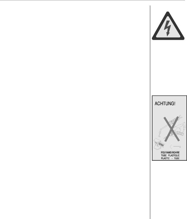
Working on the vehicle electrical system
–Always disconnect the batteries before working on the electrical system. Disconnect the earth cable rst and connect it last when reconnecting.
–Measure voltage only using a suitable measurement device.
The input resistance of the measurement device must be at least 10 MΩ.
–Tow-start the vehicle only with the batteries connected (minimum charge 40%)! Do not use a boost-charger to jump-start the vehicle! Always disconnect the positive and negative leads before boost-charging batteries.
–Disconnect the batteries and recharge them every 4 weeks if the vehicle is not in use.
–The ignition must be switched off before the wiring harness plugs of the electronic control units are disconnected or connected up.
Important! Battery gases are explosive!
–Oxyhydrogen gas may form in enclosed battery boxes. Take particular care after long journeys and after charging the batteries with a battery charger.
–When the batteries are disconnected this gas may be ignited by sparks produced by other continuously operating consumers, the tachograph etc. that cannot be shut down. Blow compressed air through the battery box before disconnecting the batteries!
–Avoidshortcircuitscausedbypolarityreversalorbyplacingmetalobjects(spanners, mole grips, etc.) on the battery terminals.
Caution! Battery acid is poisonous and corrosive!
–Wear appropriate protective clothing (gloves, protective apron) when handling batteries.
Do not tilt batteries, acid may leak out.
16 |
K100 2nd edition |
INTRODUCTION
Electric welding
–Connect up the "ANTIZAP SERVICE MONITOR" protective device (MAN item number80.78010.0002)inaccordancewiththeinstructionssuppliedwiththedevice.
–If this device is not available, disconnect the batteries and connect the positive cable to the negative cable in order to make a conductive connection.
–Alwaysearththeweldingequipmentascloseaspossibletotheweldingarea. Donot lay the cables to the welding equipment in parallel to electrical cables in the vehicle.
–The chassis is not intended for use as an earth return. If attachments are to betted to the vehicle (e.g. a taillift), additional earth (ground) lines with an adequate cross-section must be tted as well. Otherwise the earth connection may be created along wire cables, wiring harnesses, gearbox shafts, gears etc. Severe damage could result.
Painting
–If paint spraying is to be carried out, do not expose the electronic components to high temperatures (max. 95 °C) for more than brief periods; a time of up to 2 hours is permissible at a maximum of 85 °C. Disconnect the batteries.
Working on plastic tubes - Danger of damage and re!
–The warning sign opposite is attached to the inside of the diesel fuel or heating oil tank ap. It warns you against welding or drilling near to plastic tubes.
Working with the cab tilted
–Keep the tilting area in front of the cab clear.
–Keep out of the area between the cab and the chassis during the tilting process. This is a danger area!
–Always tilt the cab past the tilting point to its nal position.
Working on the air-conditioning system
–Refrigerant uids and vapours represent a health hazard, avoid contact with them and protect your eyes and hands.
–Do not drain gaseous refrigerants in enclosed rooms.
–Do not mix CFC-free refrigerant R 134a with R 12 (CFC) refrigerant.
2.Notes on preventing damage and premature wear on units
–Only subject units to the load which they have been designed to cope with in accordance with their designated use. Do not overload them.
–If a fault occurs during operation, determine its cause immediately and correct the problem before the fault can get any worse.
–Clean the units thoroughly before repairs. Ensure that no dirt, sand or foreign objects can get into the units whilst carrying out repairs.
–Always use genuine parts. Fitting “equivalent parts” made by other companies can lead to severe damage, and the workshop that did the work will be responsible for it. See the section entitled "Limited liability for accessories and parts".
–Never run a unit dry, in other words always make sure that it has been lled with oil before running it.
–Never run engines without coolant.
–Apply a suitable information sign to units that are not ready to be operated.
K100 2nd edition |
17 |

INTRODUCTION
–Only use service products (engine and gearbox oil as well as antifreeze and anti-corrosion protection) that have been approved by MAN. Keep your workplace clean.
–Comply with the speci ed maintenance intervals.
–Donot llengine/gearoilabovethemaximumlevelmark. Donotexceedthemaximumpermittedoperational tilt.
–Severe damage to the unit could result from failure to follow these regulations.
3. Limited liability for accessories and parts
In your own interests, you are recommended to use only accessories expressly approved by MAN and genuineMANparts. Thereliability,safetyandsuitabilityofthesepartsandaccessorieshavebeendetermined speci cally for MAN vehicles. Despite constant market observation, we cannot judge the aspects of other products,norcanweacceptresponsibilityforthem – eveniftheyhavebeenof ciallyapprovedbytheGerman TÜV technical inspection authorities or some other of cial body.
Attachments and special bodies
Comply with the safety instructions and regulations issued by the body builder in question if attachments or special bodies have been tted. Always follow the instructions in the appropriate MAN Guide to Fitting Bodies (www.manted.de). Written approval/release/con rmation from department TDB is required if the appropriate MAN Guide to Fitting Bodies is not complied with.
Taking out of operation and storing
The special measures described in MAN Works Standard M 3069 Part 3 apply if buses or trucks are to be withdrawn from service or stored for a period longer than 3 months.
4. Handling brake pads and similar components
–Harmful dust may be released when brake pads are machined, in particular during skimming and grinding as well as when wheel brakes are blown out.
–Please take the necessary precautionary measures and observe the following safety advice to avoid possible damage to your health:
–If possible, carry out the work in question in the open or in an area equipped with an ef cient ventilation system.
–If possible, use hand-operated or slow-running tools, equipped with a dust-collector if required.
–Fast-running tools should always be tted with such devices.
–If possible, wet the workpiece prior to cutting or drilling.
–Dispose of brake pads or linings as hazardous waste in an environmentally sound manner.
5. Regulations for avoiding injury and environmental contamination
Coolant
Treat undiluted antifreeze as hazardous waste. Follow the instructions issued by the relevant local authority when disposing of used coolant (mixture of antifreeze and water).
Cleaning the cooling circuit
Do not pour cleaning uids and rinsing water down the drain if this practice is restricted by speci c local regulations. However, the cleaning uid and rinsing water must in all cases have been passed through an oil trap with a sludge trap.
Cleaning the lter insert
When blowing compressed air through the lter insert, make sure the lter dust is collected by a vacuum or is blown into a dust collection bag. Otherwise, use a respiratory protection mask. Wear rubber gloves or use a skin barrier hand cream when washing out the insert, because cleaning agents have aggressive grease-dissolving characteristics.
Engine/gear oil, lter cartridges, elements and box-type lters, desiccant cartridges
Only dispose of used oil at an approved collection point or depot. It is extremely important that oil is not poured down the drain or onto the ground since it can pollute drinking water! Filter inserts, cartridges and box-type lters (oil and fuel lters, desiccant cartridges for the air dryer) are classi ed as hazardous waste materials and must be disposed of properly. Please follow the instructions of your relevant local authority.
Used engine/gear oil
Lengthy or repeated skin contact with any type of engine/gear oil removes grease from the skin. This can causedryskin,irritationorskinin ammation. Inadditiontothesehazards,usedengineoilcontainsdangerous materials which can cause skin cancer.
18 |
K100 2nd edition |
INTRODUCTION
6. Health protection precautions
–Avoid lengthy, excessive or repeated skin contact with used oils.
–Protect your skin using a suitable skin protection agent or protective gloves.
–Clean areas of skin which have come into contact with engine oil.
–Wash the areas thoroughly with soap and water.
–A nail brush enables more effective cleaning.
–Special cleaning agents make it easier to clean dirty hands.
–Do not use petrol, diesel oil, gas oil, thinners or solvents.
–Apply a greasy skin cream after cleaning your skin.
–Change out of clothing or shoes which have become soaked with oil.
–Never put oil-soaked rags into your clothing pockets.
Take care to dispose of used engine/gear oil properly.
- Oils can damage groundwater quality -
Therefore, never pour used oil onto the ground, into water or down the drains or sewers. Failure to comply with these instructions can lead to prosecution.
Collect and dispose of used oil carefully. Contact the point of sale, supplier or your local authority for information about collection depots.
Extract from "Information on dealing with used engine oil"
The Mineral Oil Traders’ Association (MINERALÖLWIRTSCHAFTSVERBAND E.V.) Steindamm 71, D-20099 Hamburg
K100 2nd edition |
19 |

INTRODUCTION
OVERVIEW OF MODELS
These wiring diagrams - 03.2010 edition - apply to the following vehicles.
Model |
Model designation |
|
|
|
Model |
Model designation |
|
|
||||
06S - 1580 TGS 18.D20/D26 4X2 BL |
|
|
26X - 0150 TGX 26/33.D20/D26 6X4 BB |
|
||||||||
06S - 1581 TGS 18.D20/D26 4X2 BL |
|
|
28X - 0006 TGX 28 6X4 BB-CKD |
|
|
|||||||
89S - 0161 TGS 28.D20/D26 6X2-2 BL |
|
|
30X - 0273 TGX 26/33.D20/D26 6X4 BL |
|
||||||||
89S - 0162 TGS 28.D20/D26 6X2-2 BL |
|
|
|
|
|
|
|
|
|
|
||
Overview of wiring diagrams classi ed according to model designation |
|
|
|
|
||||||||
|
|
|
|
|
|
|
|
|
|
|
||
|
|
|
Model |
Model |
Model |
Model |
Model |
|
Model |
Model |
||
Name |
|
Item no.: |
06S |
- |
|
06S - |
89S - |
89S - |
26X - |
|
28X - |
30X - |
|
|
|
|
|
||||||||
|
|
|
1580 |
|
1581 |
0161 |
0162 |
0150 |
|
0006 |
0273 |
|
ASR check lamp |
81.99192.1358 |
X |
|
|
X |
X |
X |
|
|
|
|
|
|
|
|
|
|
|
|
|
|
|
|
|
|
Seat belt indicator, driver |
81.99192.1374 |
X |
|
|
X |
X |
X |
X |
|
X |
X |
|
|
|
|
|
|
|
|
|
|
|
|
|
|
Engine brake |
81.99192.1656 |
X |
|
|
X |
X |
X |
X |
|
|
X |
|
|
|
|
|
|
|
|
|
|
|
|
|
|
Battery master switch, |
81.99192.2495 |
|
|
|
|
|
|
|
|
X |
|
|
mechanical |
|
|
|
|
|
|
|
|
|
|
||
|
|
|
|
|
|
|
|
|
|
|
|
|
Trailer socket 24V 7-pole |
81.99192.2496 |
|
|
|
|
|
|
|
|
X |
|
|
|
|
|
|
|
|
|
|
|
|
|
|
|
Trailer socket 24V 7-pole |
81.99192.2498 |
X |
|
|
X |
X |
X |
X |
|
|
X |
|
|
|
|
|
|
|
|
|
|
|
|
|
|
Side marker lights |
81.99192.2592 |
|
|
|
|
X |
X |
X |
|
X |
X |
|
|
|
|
|
|
|
|
|
|
|
|
|
|
Tachograph check lamp |
81.99192.3043 |
X |
|
|
X |
X |
X |
X |
|
X |
X |
|
|
|
|
|
|
|
|
|
|
|
|
|
|
Door module |
81.99192.3077 |
X |
|
|
X |
X |
X |
X |
|
X |
X |
|
|
|
|
|
|
|
|
|
|
|
|
|
|
Series standard wiring |
81.99192.3079 |
X |
|
|
X |
X |
X |
X |
|
X |
X |
|
diagram |
|
|
|
|
||||||||
|
|
|
|
|
|
|
|
|
|
|
|
|
Anti-jackknife brake for EBS5 |
81.99192.3082 |
|
|
|
|
|
|
|
|
X |
|
|
Fan clutch |
with speed |
81.99192.3120 |
|
|
|
|
|
|
X |
|
|
X |
feedback |
|
|
|
|
|
|
|
|
|
|||
|
|
|
|
|
|
|
|
|
|
|
|
|
Basicline radio |
81.99192.3134 |
X |
|
|
X |
X |
X |
X |
|
X |
|
|
|
|
|
|
|
|
|
|
|
|
|
|
|
Cab, T-CAN, standard |
81.99192.3173 |
|
|
|
|
|
|
|
|
X |
|
|
|
|
|
|
|
|
|
|
|
|
|
|
|
T-CAN standard/ECAS |
81.99192.3174 |
X |
|
|
X |
|
|
|
|
|
|
|
|
|
|
|
|
|
|
|
|
|
|
|
|
T-CAN standard/ECAS |
81.99192.3175 |
|
|
|
|
X |
X |
|
|
|
X |
|
/Intarder |
|
|
|
|
|
|
|
|
||||
|
|
|
|
|
|
|
|
|
|
|
|
|
T-CAN standard/Intarder |
81.99192.3178 |
|
|
|
|
|
|
X |
|
|
|
|
|
|
|
|
|
|
|
|
|
|
|
|
|
T-CAN (KSM) |
81.99192.3180 |
X |
|
|
X |
X |
X |
X |
|
|
X |
|
T-CAN terminating resistor in |
81.99192.3221 |
X |
|
|
X |
X |
X |
X |
|
X |
X |
|
cab |
|
|
|
|
|
|
|
|
|
|
|
|
ASR slip thresholds button |
81.99192.3222 |
X |
|
|
X |
X |
X |
|
|
|
|
|
|
|
|
|
|
|
|
|
|
|
|
|
|
Transverse differential lock, |
81.99192.3233 |
|
|
|
|
X |
X |
|
|
|
|
|
rear axle (2-axle vehicle) |
|
|
|
|
|
|
|
|
|
|
|
|
Interaxle and transverse |
|
|
|
|
|
|
|
|
|
|
|
|
differential |
lock, rear axle |
81.99192.3235 |
|
|
|
|
|
|
X |
|
X |
X |
(3-axle vehicle) |
|
|
|
|
|
|
|
|
|
|
|
|
I-CAN cab (standard) |
81.99192.3237 |
X |
|
|
X |
X |
X |
X |
|
X |
X |
|
|
|
|
|
|
|
|
|
|
|
|
|
|
Electronic Brake System EBS |
81.99192.3246 |
X |
|
|
X |
|
|
|
|
|
|
|
5 (2-axle vehicle) |
|
|
|
|
|
|
|
|
|
|
|
|
20 |
K100 2nd edition |

INTRODUCTION
|
|
|
Model |
Model |
Model |
Model |
Model |
Model |
Model |
||
Name |
|
Item no.: |
06S |
- |
06S - |
89S - |
89S |
- |
26X - |
28X - |
30X - |
|
|
|
|||||||||
|
|
|
1580 |
1581 |
0161 |
0162 |
0150 |
0006 |
0273 |
||
Electronic Brake System EBS |
81.99192.3247 |
|
|
|
X |
X |
|
X |
X |
X |
|
5 (3-axle vehicle) |
|
|
|
|
|
|
|
|
|
|
|
ECAS 2 (4x2 - semitrailer) |
81.99192.3248 |
X |
|
X |
|
|
|
|
|
|
|
|
|
|
|
|
|
|
|
|
|
|
|
ECAS 2 (4x2) |
|
81.99192.3250 |
|
|
|
|
|
|
|
|
X |
ECAS 2 (6x2 optionally with |
81.99192.3253 |
|
|
|
X |
X |
|
|
|
|
|
ALM/crane) |
|
|
|
|
|
|
|
|
|
|
|
EVB (Exhaust Valve Brake), |
81.99192.3260 |
|
|
|
|
|
|
|
X |
|
|
controlled |
|
|
|
|
|
|
|
|
|
|
|
Window lifter, button in shift |
81.99192.3267 |
X |
|
X |
X |
X |
|
X |
X |
X |
|
console |
|
|
|
|
|
|
|
|
|
|
|
|
|
81.99192.3276 |
|
|
|
|
|
|
|
|
|
Gearbox / manual gearbox |
replaced by |
X |
|
X |
X |
X |
|
X |
|
X |
|
|
|
81.99192.3748 |
|
|
|
|
|
|
|
|
|
Trailer charge, 24V |
81.99192.3292 |
|
|
|
|
|
|
|
X |
|
|
|
|
|
|
|
|
|
|
|
|
|
|
Interior lighting, roof, white |
81.99192.3293 |
X |
|
X |
X |
X |
|
X |
X |
X |
|
/red |
|
|
|
|
|
|
|
|
|
|
|
Intarder |
|
81.99192.3295 |
|
|
|
X |
X |
|
X |
|
X |
Seat heating, driver |
81.99192.3298 |
|
|
|
|
|
|
X |
|
X |
|
|
|
|
|
|
|
|
|
|
|
|
|
Customer-speci c control |
81.99192.3300 |
X |
|
X |
X |
X |
|
X |
|
X |
|
module (KSM) |
|
|
|
|
|||||||
|
|
|
|
|
|
|
|
|
|
|
|
Preparation, |
transverse |
|
|
|
|
|
|
|
|
|
|
differential lock, rear axle |
81.99192.3303 |
X |
|
X |
|
X |
|
|
|
|
|
(2-axle vehicle) |
|
|
|
|
|
|
|
|
|
|
|
Fuel lter heater |
81.99192.3304 |
X |
|
X |
X |
X |
|
X |
X |
X |
|
|
|
|
|
|
|
|
|
|
|
|
|
Fuel lter heater, Separ |
81.99192.3305 |
X |
|
X |
X |
X |
|
X |
|
X |
|
|
|
|
|
|
|
|
|
|
|
|
|
Voltage transformer, 12V |
81.99192.3313 |
X |
|
X |
X |
X |
|
X |
|
X |
|
Headlight beam regulator |
81.99192.3314 |
X |
|
X |
X |
X |
|
X |
X |
X |
|
Engine brake, automatic, off |
81.99192.3316 |
X |
|
X |
|
|
|
|
X |
|
|
START/STOP |
device on |
81.99192.3317 |
X |
|
X |
X |
X |
|
X |
X |
X |
engine |
|
|
|
||||||||
|
|
|
|
|
|
|
|
|
|
|
|
Pritarder/Intarder, automatic, |
81.99192.3337 |
|
|
|
X |
X |
|
X |
|
X |
|
off |
|
|
|
|
|
|
|
|
|
|
|
Bunk light, bottom |
81.99192.3349 |
X |
|
X |
X |
X |
|
X |
X |
X |
|
|
|
|
|
|
|
|
|
|
|
|
|
Storage locker lighting, top |
81.99192.3350 |
X |
|
X |
X |
X |
|
|
|
|
|
(left, middle) |
|
|
|
|
|
|
|
|
|
|
|
Storage locker lighting, top |
81.99192.3351 |
|
|
|
|
|
|
X |
X |
X |
|
(left, middle, right) |
|
|
|
|
|
|
|
|
|
|
|
Central lubrication system |
81.99192.3352 |
X |
|
X |
X |
X |
|
|
|
|
|
|
|
|
|
|
|
|
|
|
|
|
|
Fog lamps/additional high |
81.99192.3366 |
X |
|
X |
X |
X |
|
|
X |
|
|
beam headlights and |
|
|
|
|
|||||||
cornering light |
|
|
|
|
|
|
|
|
|
|
|
Sockets in cab, 12V and 24V |
81.99192.3367 |
X |
|
X |
X |
X |
|
X |
|
X |
|
|
|
|
|
|
|
|
|
|
|
|
|
Preparation, |
central |
81.99192.3379 |
|
|
|
|
|
|
X |
|
X |
lubrication system |
|
|
|
|
|
|
|
||||
|
|
|
|
|
|
|
|
|
|
||
K100 2nd edition |
21 |

INTRODUCTION
|
|
Model |
Model |
Model |
Model |
Model |
Model |
Model |
||
Name |
Item no.: |
06S |
- |
06S - |
89S - |
89S - |
26X - |
28X - |
30X |
- |
|
|
|||||||||
|
|
1580 |
1581 |
0161 |
0162 |
0150 |
0006 |
0273 |
||
Storage locker lighting, rear |
81.99192.3395 |
X |
|
X |
X |
X |
X |
X |
X |
|
left |
|
|
|
|
|
|
|
|
|
|
Storage locker lighting, rear |
81.99192.3396 |
X |
|
X |
X |
X |
X |
X |
X |
|
right |
|
|
|
|
|
|
|
|
|
|
Table of contents |
81.99192.3400 |
X |
|
X |
X |
X |
X |
X |
X |
|
I-CAN roof (standard) |
81.99192.3405 |
X |
|
X |
X |
X |
X |
X |
X |
|
|
|
|
|
|
|
|
|
|
|
|
Interior lights with ambient |
81.99192.3461 |
|
|
|
|
|
X |
X |
X |
|
light |
|
|
|
|
|
|
||||
|
|
|
|
|
|
|
|
|
|
|
Topline radio |
81.99192.3490 |
|
|
|
|
|
|
|
X |
|
|
|
|
|
|
|
|
|
|
|
|
Multifunctional steering wheel |
81.99192.3501 |
X |
|
X |
|
|
|
|
|
|
|
|
|
|
|
|
|
|
|
|
|
Electric cab tilt mechanism |
81.99192.3617 |
|
|
|
|
|
X |
|
X |
|
|
|
|
|
|
|
|
|
|
|
|
EDC7 Euro 3 D20... |
81.99192.3624 |
X |
|
X |
X |
X |
|
|
|
|
|
|
|
|
|
|
|
|
|
|
|
EDC7 Common Rail Euro 3 |
81.99192.3625 |
|
|
|
|
|
X |
X |
X |
|
D2676 LF, E-EGR |
|
|
|
|
|
|
|
|
|
|
Gearbox / manual gearbox |
81.99192.3748 |
|
|
|
|
|
|
X |
|
|
22 |
K100 2nd edition |
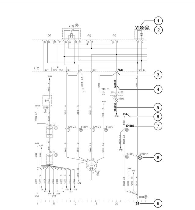
INTRODUCTION
EXPLANATORY NOTES TO THE WIRING DIAGRAMS
1 Electrical component designation (example: diode V100 on the central electrical system, number 53)
2 Installation position on the front of the central electrical system (here: stamped number 53)
3Plug connection on the rear of the central electrical system (here: connector 78, connection 8)
4Cable designation, number, with abbreviated colour name in the case of coloured cables, cross section information only given if different from 12
Note: For cable number or cable name, see MAN-cats®.
5Cable designation, number in brackets: conductor pathways on a p.c.b.
6Line interruption with information about where the line continues, with sheet number(here: sheet2 – notpagenumber) and path number (here: path 4)
7Plug connection (example: 1-pin plug connection X104)
8Installation location of the component (see: identi cations of installation positions)
9Current path (numbered from 1 to 55/60 on each diagram)
K100 2nd edition |
23 |
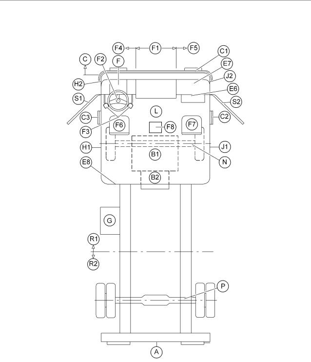
INTRODUCTION
Installation positions for location identi ers
Installation positions for left-hand-drive vehicles (TGS/TGX)
(A) |
Rear of vehicle |
(F6) |
Driver’s seat |
(B1) |
Engine |
(F7) |
Co-driver’s seat |
(B2) |
Gearbox |
(F8) |
Shift console |
(C) |
Front of vehicle |
(G) |
Battery box |
(C1) |
Bumper |
(H1) |
B-pillar, driver’s side |
(C2) |
Entrance, right |
(H2) |
A-pillar, driver’s side |
(C3) |
Entrance, left |
(J1) |
B-pillar, co-driver's side |
(E6) |
Area of central electrical system |
(J2) |
A-pillar, co-driver’s side |
(E7) |
Control unit plug-in modules |
(L) |
Ceiling/roof |
(E8) |
Back wall of cab |
(N) |
Front axle |
(F) |
Instrument panel |
(P) |
Rear axle |
(F1) |
Mid-section |
(R1) |
Front frame sections |
(F2) |
Steering column / steering wheel |
(R2) |
Rear frame section |
(F3) |
Pedals |
(S1) |
Door, left |
(F4) |
Front wall inside left |
(S2) |
Door, right |
(F5) |
Front wall inside right |
|
|
24 |
K100 2nd edition |

SERIES STANDARD WIRING DIAGRAM
K100 2nd edition |
25 |

SERIES STANDARD WIRING DIAGRAM
WIRING DIAGRAM NO. 81.99192.3079
A = Voltage supply, starting system sheet 1 of 22
Date: 09.2007
Legend |
|
A100 |
Central electrical system |
A302 |
Central computer 2 |
A403 |
Vehicle management computer |
A435 |
Control unit, EDC |
F354 |
Main fuse (terminal 30-1) |
F355 |
Main fuse (terminal 30-2) |
F399 |
Fuse, alternator (terminal 15) |
G100 |
Battery 1 |
G101 |
Battery 2 |
G102 |
Alternator 1 |
K171 |
Relay, consumers (terminal 15) |
M100 |
Starter |
Q101 |
Steering lock |
X100 |
Ground connection, engine |
X669 |
Plug conn., starter interlock |
X1364 |
Jumper, central electrical system (central on-board computer) 90/1-90/2 |
X1365 |
Jumper, central electrical system (central on-board computer) 90/2-91 |
X1541 |
Plug conn., potential bushing + |
X1551 |
Plug conn., engine/EDC/gearbox II |
X1913 |
Jumper, line 30076 (motor power box) |
X1966 |
Plug conn., ignition lock |
X2549 |
Plug conn., IMR (starter) |
X4829 |
Plug conn., ignition lock (terminal R) |
K100 2nd edition |
26 |

SERIES STANDARD WIRING DIAGRAM
A = Voltage supply, starting system sheet 1 of 22
K100 2nd edition |
27 |

SERIES STANDARD WIRING DIAGRAM
WIRING DIAGRAM NO. 81.99192.3079
A = On-board computer voltage supply / B = EBS voltage supply / C = Vehicle management computer voltage supply sheet 2 of 22
Date: 03.2005
Legend |
|
A100 |
Central electrical system |
A302 |
Central computer 2 |
A403 |
Vehicle management computer |
F160 |
Fuse, EBS (ABS), trailer voltage supply |
F161 |
Fuse, EBS (ABS), pressure control valve voltage supply |
F162 |
Fuse, EBS (ABS), control |
F243 |
Fuse, central on-board computer continuous positive |
F244 |
Fuse, central on-board computer (terminal 30-1) |
F245 |
Fuse, central on-board computer (terminal 30-2) |
F246 |
Fuse, central on-board computer (terminal 15) |
F371 |
Voltage supply, vehicle management computer (terminal 30) |
F372 |
Voltage supply, vehicle management computer (terminal 15) |
F400 |
Fuse, steering lock |
F522 |
Fuse, line 30000 |
F523 |
Fuse, line 30000 |
X1064 |
Jumper on central electrical system, item 37 (pin1-2) |
X1557 |
Plug conn., frame, left |
X1644 |
Earthing point, cab, next to central electrical system |
X4643 |
Potential distributor, line 59104 |
——– |
—————————————————————– |
1 |
EBS |
K100 2nd edition |
28 |
Loading...