


TGA
Guidelines to fi tting bodies
TRUCKNOLOGY
(TGA)
Edition 2012 Version 1.1
®
GENERATION A

PUBLISHER
MAN Truck & Bus AG
(mentioned in the text below “MAN“)
SMTST Department
Dachauer Str. 667
D - 80995 Munich
E-Mail:
esc@man.eu
Fax:
+ 49 (0) 89 1580 4264
www.manted.de
We reserve the right to make changes in the course of technical development.
© 2012 MAN Truck & Bus Aktiengesellschaft
Reprinting, reproduction or translation, even of excerpts, is not permitted without the written permission of MAN.
All rights, in particular under copyright, are strictly reserved by MAN.
Trucknology
Where designations are trademarks they are, even without the
®
and MANTED® are registered trademarks of MAN Truck & Bus AG
®
or ™ sign, acknowledged as the proprietor‘s protected marks.

TRUCKNOLOGY
®
GENERATION A (TGA)
1. Applicability and legal agreements
1.1 Applicability
1.2 Legal agreements and approval procedure
1.2.1 Preconditions
1.2.2 Responsibility
1.2.3 Quality assurance
1.2.4 Approval
1.2.5 Submission of documents
1.2.6 Registration
1.2.7 Liability for defects
1.2.8 Product liability
1.2.9 Operational reliability and road safety
1.2.10 Manuals from body and conversion companies
1.2.11 Limitation of liability for accessories/spare parts
2. Product designations
2.1 Vehicle designation and wheel formula
2.1.1 Door designation
2.1.2 Variant descriptor
2.1.3 Wheel formula
2.1.4 Suffi x
2.2 Model number, vehicle identifi cation number, vehicle number, basic vehicle number
2.3 Use of logos
2.4 Cabs
2.5 Engine variants
3. General
3.1 Axle overload, one-sided loading
3.2 Minimum front axle load
3.3 Wheels, rolling circumference
3.4 Permissible overhang
3.5 Theoretical wheelbase, overhang, theoretical axle centreline
3.6 Calculating the axle load and weighing procedure
3.7 Checking and adjustment procedures once body has been fi tted
3.8 Notes on MAN Hydrodrive
®
1
1
1
1
2
2
3
3
4
7
8
8
10
11
11
11
11
11
12
13
14
18
19
21
22
22
24
25
25
26
28
29
30
TRUCKNOLOGY® GENERATION A (TGA) I

4. Modifying the chassis
4.1 Frame material
4.1.1 Subframe material
4.2 Corrosion protection
4.3 Drill holes, riveted joints and screw connections on the frame
4.4 Modifying the frame
4.4.1 Welding the frame
4.4.2 Modifying the frame overhang
4.4.3 Modifi cations to the wheelbase
4.5 Retrofi tting additional equipment add-on components or accessories
4.5.1 Retrofi tting additional or larger fuel tanks after factory delivery
4.6 Propshafts
4.6.1 Single joint
4.6.2 Jointed shaft with two joints
4.6.3 Three-dimensional propshaft layout
4.6.3.1 Propshaft train
4.6.3.2 Forces in the propshaft system
4.6.4 Modifying the propshaft layout in the driveline of MAN chassis
4.7 Modifying the wheel formula
4.7.1 Safety-related components
4.8 Coupling devices
4.8.1 Basics
4.8.2 Trailer coupling, D value
4.9 Tractor units and converting the vehicle type - truck / tractor
4.9.1 Articulated vehicles
4.9.2 Converting trucks into tractor units or tractor units into trucks
4.10 Modifying the cab
4.10.1 General
4.10.2 Spoilers, roof extensions, roofwalk
4.10.3 Roof sleeper cabs
4.11 Add-on frame components
4.11.1 Rear underride guard
4.11.2 FUP - front underride protection
4.11.3 Sideguards
4.12 Modifi cations to engine systems
4.12.1 Modifi cations to the air intake and exhaust gas routing
4.12.2 Additional requirements if changes are made to the AdBlue
®
system/exhaust
system on Euro5 vehicles
4.12.3 Engine cooling
4.12.4 Engine encapsulation, noise insulation
4.13 Fitting other manual gearboxes, automatic transmissions and transfer boxes
30
30
35
35
35
38
38
40
42
48
48
49
49
50
51
52
52
53
53
53
55
55
56
56
56
59
59
59
59
62
63
63
65
66
68
68
70
70
78
78
78
TRUCKNOLOGY® GENERATION A (TGA) II

5. Bodies
5.1 General
5.1.1 Machinery Directive
5.1.2 CE marking
5.2 Corrosion protection
5.3 Subframes
5.3.1 General
5.3.2 Permissible materials, yield points
5.3.3 Subframe design
5.3.4 Attaching subframes and bodies
5.3.5 Screw connections and riveted joints
5.3.6 Flexible connection
5.3.7 Rigid connection
5.4 Bodies
5.4.1 Testing of bodies
5.4.2 Platform and box bodies
5.4.3 Tail-lifts
5.4.4 Interchangeable containers
5.4.5 Self-supporting bodies without subframe
5.4.6 Single-pivot body
5.4.7 Tank and container bodies
5.4.8 Tippers
5.4.9 Set-down, sliding set-down and sliding roll-off tippers
5.4.10 Propping air-sprung vehicles
5.4.11 Loading cranes
5.4.12 Cable winches
5.4.13 Transport mixers
5.4.14 Car transporter
78
78
80
82
83
83
83
84
86
87
88
91
94
94
94
95
96
104
105
105
108
110
111
112
113
123
123
124
TRUCKNOLOGY® GENERATION A (TGA) III

6. Electrics, electronics, wiring
6.1 General
6.2 Routing cables, earth cable
6.3 Handling batteries
6.3.1 Handling and maintaining the batteries
6.3.2 Handling and maintaining batteries with PAG technology
6.4 Additional wiring diagrams and wiring harness drawings
6.5 Fuses, additional power consumers
6.6 Lighting installations
6.7 Electromagnetic compatibility
6.8 Radio equipment and aerials
6.9 Interfaces on the vehicle, preparations for the body
6.9.1 Electrical connections for tail-lifts
6.9.2 Start-stop control on frame end
6.9.3 Tapping into the speed signal
6.10 Electronics
6.10.1 Display and instrumentation concept
6.10.2 Diagnostics concept and parameterisation using MAN-cats
6.10.3 Parameterisation of the vehicle electronics
6.10.4 ESP yaw rate sensor
125
125
125
125
125
126
127
127
130
130
131
133
133
133
133
134
134
®
134
134
135
TRUCKNOLOGY® GENERATION A (TGA) IV

7. Power take-off (See separate booklet)
8. Brakes, lines
8.1 ALB, EBS braking system
8.2 Brake and compressed air lines
8.2.1 Basic principles
8.2.2 Voss 232 system plug connectors
8.2.3 Installing and attaching lines
8.2.4 Compressed air loss
8.3 Connecting additional air consumers
8.4 Retrofi tting continuous brakes not manufactured by MAN
9. Calculations
9.1 Speed
9.2 Effi ciency
9.3 Tractive force
9.4 Gradeability
9.4.1 Distance travelled on uphill or downhill gradients
9.4.2 Angle of uphill or downhill gradient
9.4.3 Calculating the gradeability
9.5 Torque
9.6 Power output
9.7 Rotational speeds for power take-offs at the transfer case
9.8 Driving resistances
9.9 Turning circle
9.10 Axle load calculation
9.10.1 Performing an axle load calculation
9.10.2 Calculation of weight with trailing axle lifted
9.11 Support length for bodies without subframes
9.12 Coupling devices
9.12.1 Trailer coupling
9.12.2 Rigid drawbar trailers / central axle trailers
9.12.3 Fifth-wheel coupling
136
136
136
136
136
137
138
140
140
142
142
142
143
144
145
145
145
146
150
151
153
154
157
159
159
162
164
165
165
165
167
The ESC numbers stated in the illustrations are purely for internal reference.
They are of no consequence to the reader.
If not otherwise stated: all dimensions in mm, all weights and loads in kg
TRUCKNOLOGY® GENERATION A (TGA) V

1. Applicability and legal agreements
1.1 Applicability
The statements in this guide are binding. If technically feasible, exceptions will be approved only if a written request has been
submitted to the SMTSE-ESC department at MAN, (see „Publisher“ above).
1.2 Legal agreements and approval procedure
1.2.1 Preconditions
In addition to this Guide, the company carrying out the work must observe all
• laws and decrees
• accident prevention regulations
• operating instructions
relating to the operation and construction of the vehicle. Standards are technical standards; they are therefore minimum requirements.
Anyone who does not endeavour to observe these minimum requirements is regarded as operating negligently.
Standards are binding when they form part of regulations.
Information given by MAN in reply to telephone enquiries is not binding unless confi rmed in writing. Enquiries are to be directed to
the relevant MAN department. Information refers to conditions of use that are usual within Europe. Dimensions, weights and other basic
data that differ from these must be taken into consideration when designing the body, mounting the body and designing the subframe.
The company carrying out the work must ensure that the entire vehicle can withstand the conditions of use that it is expected
to experience.
For certain types of equipment, such as loading cranes, tail-lifts, cable winches etc, the respective manufacturers have developed
their own body regulations. If, when compared with this MAN Guide, they impose further conditions, then these too must be observed.
References to
• legal stipulations
• accident prevention regulations
• decrees from professional associations
• work regulations
• other guidelines and sources of information
are not in any way complete and are only intended as ideas for further information.
They do not replace the company’s obligation to carry out its own checks.
Fuel consumption is considerably affected by modifi cations to the vehicle, by the body and its design and by the operation of equipment
driven by the vehicle’s engine. It is therefore expected that the company carrying out the work implements a design that facilitates
the lowest possible fuel consumption.
TRUCKNOLOGY® GENERATION A (TGA) 1

1.2.2 Responsibility
The responsibility for proper
• design
• production
• installation of bodies
• modifi cation to the chassis
always lies fully with the company that is manufacturing the body, installing it or carrying out modifi cations (manufacturer’s liability).
This also applies if MAN has expressly approved the body or the modifi cation. Bodies/conversions that have been approved in writing
by MAN do not release the body manufacturer from his responsibility for the product. Should the company carrying out the work detect
a mistake either in the planning stage or in the intentions of
• the customer
• the user
• its own personnel
• the vehicle manufacturer
then that mistake must be brought to the attention of the respective party.
The company is responsible for seeing that the vehicle’s
• operational safety
• traffi c safety
• maintenance possibilities and
• handling characteristics
do not exhibit any disadvantageous properties.
With regard to traffi c safety, the company must operate in accordance with the state of the art and in line with the recognised rules in
the fi eld in matters relating to
• the design
• the production of bodies
• the installation of bodies
• the modifi cation of chassis
• instructions and
• operating instructions.
Diffi cult conditions of use must also be taken into account.
1.2.3 Quality assurance
In order to meet our customers’ high quality expectations and in view of international product/manufacturer liability legislation an
on-going quality monitoring programme is also required for conversions and body manufacture/installation. This requires a functioning
quality assurance system. It is recommended that the body manufacturer sets up and provides evidence of a quality system that
complies with the general requirements and recognised rules (e.g. DIN EN ISO 9000 et seq. or VDA 8).
Evidence of a qualifi ed system can be provided for example by:
TRUCKNOLOGY® GENERATION A (TGA) 2

If MAN is the party awarding the contract for the body or conversion evidence of qualifi cation will be requested.
MAN Truck & Bus AG reserves the right to carry out its own system audit in accordance with VDA 8 or a corresponding process check at
the supplier’s premises. VDA volume 8 has been agreed with the following body manufacturers’ associations:
ZKF (Zentralverband Karosserie- und Fahrzeugtechnik – Central Association of Body and Vehicle Engineering) and
BVM (Bundesverband Metall Vereinigung Deutscher Metallhandwerke – Federation of German Metal Trades Associations).
It has also been agreed with the ZDH (Zentralverband des Deutschen Handwerks – Central Association of German Craft Trades).
Documents:
VDA Volume 8
„Minimum quality assurance requirements for trailer, body manufacturers“, obtainable from the Verband der Automobilindustrie e.V
(VDA) (German Engine Industry Association), http://www.vda-qmc.de.
1.2.4 Approval
Approval from MAN for a body or a chassis modifi cation is not required if the bodies or modifi cations are carried out in accordance with
this Guide. If MAN approves a body or a chassis modifi cation, then this approval refers
• In the case of bodies only to the body’s fundamental compatibility with the respective chassis and the interfaces to the body
(e.g. dimensions and mounting of the subframe)
• In the case of chassis modifi cations only to the fact that, from a design point of view, the modifi cations to the chassis in
question are fundamentally permissible.
The approval note that MAN enters on the submitted technical documents does not indicate a check on the
• Function
• Design
• Equipment of the body or the modifi cation.
Observance of this Guide does not free the user from responsibility to perform modifi cations and manufacture bodies properly from
a technical point of view. The approval note only refers to such measures or components as are to be found in the submitted technical
documents.
MAN reserves the right to refuse to issue approvals for bodies or modifi cations, even if a comparable approval has already been issued.
Later submissions for approval are not automatically treated the same as earlier ones, because technical advances achieved in
the interim period have to be taken into account.
MAN also reserves the right to change this Guide at any time or to issue instructions that differ from this Guide for individual chassis.
If several identical chassis have the same bodies or modifi cations MAN can, to simplify matters, issue a collective approval.
1.2.5 Submission of documents
Documents should only be sent to MAN if bodies/conversions diverge from this Guide. If this is the case then technical documents that
require approval or inspection must have been received by the SMTSE-ESC Department at MAN (for address see “Publisher” above).
Fitting bodies/conversion work requires prior writtien permission from MAN.
For an approval process to proceed swiftly, the following are required:
• Documents should be submitted in duplicate
• The number of individual documents should be kept to a minimum
• All the technical data and documents must be submitted.
TRUCKNOLOGY® GENERATION A (TGA) 3

The following information should be included:
• Vehicle model (see Chapter 2.2 for model code) with
- cab design
- wheelbase
- frame overhang
• · Vehicle identifi cation number or vehicle number (if already available, see Chapter 2.2)
Identifi cation of deviations from this Guide to Fitting Bodies in all documentation!
• Loads and their load application points:
- Forces from the body
- Axle load calculation
• Special conditions of use:
• Subframe:
- Material and cross-sectional data
- Dimensions
- Type of section
- Arrangement of cross members in the subframe
- Special features of the subframe design
- Cross-section modifi cations
- Additional reinforcements
- Upsweeps, etc.
• Means of connection:
- Positioning (in relation to the chassis)
- Type
- Size
- Number.
The following are not suffi cient for inspection or approval:
• Parts lists
• Brochures
• Photographs
• Other not binding information.
Drawings are only valid if they bear the number that has been assigned to them. It is therefore not permitted to draw in the bodies or
modifi cations on chassis drawings that have been provided by MAN and to submit these for approval.
1.2.6 Registration
National legislation on the registration of modifi ed vehicles shall be complied with.
Modifi cations made to the chassis shall be presented to a technical vehicle inspection centre for approval.
The company carrying out the work shall remain responsible, also after registration of the vehicle, should the competent authorities issue
a registration certifi cate with a lack of knowledge relating to the operational safety of the product.
TRUCKNOLOGY® GENERATION A (TGA) 4

Multi-stage co-operation modules in accordance with 2007/46/EC
I. Process
In line with the multi-stage process in accordance with Annex XVII of Directive 2007/46/EC each manufacturer is responsible for
the approval and conformity of production of all systems, components or separate technical units manufactured by him or added by him
to the previously built stage.
In accordance with 2007/46/EC the bodybuilder is a manufacturer in the second or further production stage.
II. Responsibilities
The bodybuilder shall always remain responsible:
• For modifi cations made by him to the basic vehicle.
• For parts already approved at an earlier stage if modifi cations made to the basic vehicle cause the approvals issued earlier
for this vehicle to be no longer applicable.
• For ensuring that modifi cations he has carried out comply with the corresponding national/international legislation,
in particular those of the target country.
• For ensuring that modifi cations he has carried out are presented to a technical vehicle inspection centre for approval.
• For ensuring that compliance with legislation is documented in a corresponding manner (test report and/or approval or
other documentation in accordance with the legal requirements of the target country).
MAN, as the manufacturer of the basic vehicle, shall always remain responsible:
• For providing upon request by the bodybuilder the available homologation documentation (EC/ECE approvals)
for the scope of supply of the basic vehicle in electronic form.
III. Identifi cation of the vehicle
The respective vehicle shall be given a vehicle identifi cation number („VIN“) which MAN issues as the manufacturer of the incomplete
basic vehicle.
The requirements set forth in Annex XVII to Directive 2007/46/EC and the associated procedure instructions published together
with it shall always apply.
IV. Conformity of production (CoP)
The requirements set forth in the specifi c EC Directives and Annex X to Directive 2007/46/EC together with the requirements set forth in
Annex 2 to the ECE Agreement of 1958 shall always apply.
V. Provision of documentation for registration/the subsequent build stages
In accordance with Annex XVII to Directive 2007/46/EC MAN, as manufacturer of the basic vehicle, shall provide the bodybuilder(s) with
the available EC/ECE system approvals together with the Certifi cate of Conformity (CoC)
1)
Only if the vehicle is EG-compliant and MAN has printed a CoC.
1)
available for the basic vehicle in electronic form.
Case 1: Registration in Germany
If MAN serves as general contractor („single invoice transactions“) the bodybuilder(s) is/are under an obligation,
as manufacturer of the second stage(s), to provide the following documentation in electronic form:
Case A: The specifi c conditions of delivery provide for the acceptance/approval and registration process to be carried
out by the vehicle manufacturer (MAN).
1. In the case of an existing and valid whole vehicle type-approval in accordance with 2007/46/EC
for the manufacturing stages, a CoC.
2. Alternatively to 1: The test reports and approval documentation required for national individual approval procedures
in accordance with Section 13 of the EC vehicle approval Directive.
TRUCKNOLOGY® GENERATION A (TGA) 5

The latest time for submitting the above stated documentation in printable form is the day the completed vehicle is returned to
the contractually agreed place of delivery.
The documentation shall be sent to the following e-mail address: documents@de.man-mn.com.
In cases where MAN receives a CoC from the bodybuilder, then original certifi cates may only be generated by MAN on behalf
of the bodybuilder.
Case B: The acceptance/approval and registration process is to be carried out by the contract partner
or by the manufacturer of the fi nal completion stage of the vehicle.
1. None. The registration process is the responsibility of the contract partner or the manufacturer of the fi nal completion
stage of the vehicle.
In all other cases the acceptance/approval and registration process is to be carried out by the manufacturer of the fi nal completion stage
of the vehicle or by the corresponding contract partner.
Case 2: Registration outside Germany but inside the area of application of Directive 2007/46/EC
If MAN serves as general contractor then the bodybuilder is under an obligation, as the fi nal stage manufacturer, to provide in
electronic form, all the necessary approval/registration documentation for all modifi cations made during the subsequent
manufacturing stages of the respective responsible sales organisation or importer which exceed the scope of the basic vehicle.
Irrespective of any general contractor status of the importers, the acceptance/approval and registration process is to be carried out
by the manufacturer of the fi nal completion stage of the vehicle or by the corresponding contract partner.
The importer in the respective country or the corresponding contract partner have the authority and responsibility
for the registration process.
MAN does not provide national data for registration purposes that exceeds that for incomplete vehicles set forth in Annex IX to Directive
2007/46/EC in its current form and as amended from time to time. This also applies in particular to national model codes and encrypted
basic technical data.
MAN as a manufacturer reserves the right – following corresponding feasibility studies and economic implementation – and after
reaching corresponding specifi cally applicable agreements with national sales organisations and importers, to provide data for national
registration which exceeds the scope of that set forth above (e.g. vehicle’s manufacturing plates etc.).
Corresponding enquiries shall be sent to the following e-mail address: documents@de.man-mn.com
VI. Confi dentiality agreement
The bodybuilder may not forward the approval documentation provided by MAN to any third parties without obtaining prior,
express permission from MAN.
The forwarding of documentation that is directly associated with the registration of the vehicle in question to persons of the institutions
listed below is excepted:
• MAN sales partners
• Technical vehicle inspection centres or testing organisations
• Approving authorities
• Registration authorities or licensing centres acting for the government
TRUCKNOLOGY® GENERATION A (TGA) 6

Type approval/homologation for
TiB (Truck in the Box),
CiB (Chassis in the Box),
BiB (Bus in the Box),
CKD (Complete Knocked Down),
SKD (Semi Knocked Down),
PKD (Partly Knocked Down)
For these versions MAN is not considered to be the manufacturer within the meaning of Directive 2007/46/EC – therefore,
the responsibility for the homologation and registration process lies with the manufacturer of these vehicles.
In principle, the substance of the contracts respectively concluded with MAN shall apply.
In principle, MAN does not provide registration-related data for completed vehicles. Exceptions include homologation documentation
for components subject to approval such as the engine. Such documentation will be provided by MAN in electronic form.
This does not however, preclude MAN from reserving the right – following corresponding feasibility studies and economic
implementation – and after reaching corresponding specifi cally applicable agreements with national sales organisations and importers,
from providing data for national registration which exceeds the scope of that set forth above (e.g. vehicle’s manufacturing plates etc.).
Corresponding enquiries shall be sent to the homologation department at MAN.
1.2.7 Liability for defects
Liability claims in respect of defects only exist within the framework of the purchasing contract between buyer and seller.
In accordance with this, liability for defects lies with the respective seller of the goods.
Claims against MAN are not valid if the fault that is the subject of the complaint was due to the fact that
• This Guide was not observed
• In view of the purpose for which the vehicle is used, an unsuitable chassis has been selected
• The damage to the chassis has been caused by
- the body
- the type of body mounting or how the body has been mounted
- the modifi cation to the chassis
- improper use.
TRUCKNOLOGY® GENERATION A (TGA) 7

1.2.8 Product liability
Any faults in the work that are identifi ed by MAN are to be corrected. Insofar as is legally permissible, MAN disclaims all liability,
in particular for consequential damage.
Product liability regulates:
• The liability of the manufacturer for its product or component
• The compensation claim made by the manufacturer against whom a claim has been made against the manufacturer of
an integral component, if the damage that has occurred is due to a fault in that component.
The company that has made the body or carried out the modifi cation is to relieve MAN of any liability to its customer or other third party
if the damage that has occurred is due to the fact that
• The company did not observe this Guide
• The body or chassis modifi cation has caused damage on account of its faulty
- design
- manufacture
- installation
- instructions
• The fundamental rules that are laid down have not been complied with in any other way.
1.2.9 Operational reliability and road safety
In order to ensure operational reliability and road safety and to maintain the validity of the warranty, the bodybuilder must observe
the instructions given in these guidelines exactly. MAN shall not be liable for non-compliance.
Before commencing work on the body, making modifi cations or starting installation work, the bodybuilder must also have knowledge
of the sections of the operator‘s manual that relate to the work he is completing. It will otherwise be impossible to recognise risks and
other persons may be endangered.
MAN cannot be liable for reliability, safety and suitability if:
• Bodies are not designed and fi tted in accordance with these guidelines
• Original parts or approved parts are replaced with other parts
• Unauthorised modifi cations are made to the vehicle
Approvals by third parties, for example Technical Inspection Agencies or approvals from public authorities, shall not be considered
suffi cient for precluding safety risks.
TRUCKNOLOGY® GENERATION A (TGA) 8

Companies carrying out work on the chassis/vehicle are liable for any damage that may be caused by poor functional and operational
safety or inadequate operating instructions.
Therefore, MAN requires the body manufacturer or vehicle conversion company to:
• Ensure the highest possible safety, in line with the state of the art
• Provide comprehensible, sufficient operating instructions
• Provide permanent, easily visible instruction plates on hazardous points for operators and/or third parties
• Observe the necessary protection measures (e.g. fire and explosion prevention)
• Provide full toxicological information
• Provide full environmental information.
Safety is top priority! All available technical means of avoiding incidents that will undermine operational safety are to be implemented.
This applies equally to
• Active safety = prevention of accidents. This includes:
- Driving safety achieved by the overall vehicle design, including the body
- Safety as a consequence of the driver’s well-being achieved by keeping occupant stress caused by vibrations,
noise, climatic conditions etc. to a minimum
- Safety as a consequence of observation and perception, in particular through the correct design of lighting systems,
warning equipment, providing sufficient direct and indirect visibility
- Safety as a consequence of operating equipment and controls this includes optimising the ease of operation of all
equipment, including that of the body.
• Passive safety = avoidance and reduction of the consequences of accidents. This includes:
- Exterior safety such as the design of the outside of the vehicle and body with respect to deformation behaviour and
the installation of protective devices
- Interior safety including the protection of occupants of vehicles and cabs that are installed by the body builders.
Climatic and environmental conditions have effects on:
• Operational safety
• Readiness for use
• Operational performance
• Service life
• Cost-effectiveness.
Climatic and environmental conditions are, for example:
• The effects of temperature
• Humidity
• Aggressive substances
• Sand and dust
• Radiation.
Suffi cient space for all parts required to carry out a movement, including all pipes and cables, must be guaranteed. The operating
instructions for MAN trucks provide information about the maintenance points on the vehicle. Regardless of what type of body is fi tted,
good access to the maintenance points must be ensured in all cases. It must be possible to carry out maintenance unhindered and
without having to remove any components. Suffi cient ventilation and/or cooling of the components is to be guaranteed.
TRUCKNOLOGY® GENERATION A (TGA) 9

1.2.10 Manuals from body and conversion companies
In the event of a body being added or modifi cations to the vehicle being carried out, the operator of the vehicle is also entitled to receive
operating instructions from the conversion company. All specifi c advantages offered by the product are of no use if the customer is
not able to:
• Handle the product safely and properly
• Use it rationally and effortlessly
• Maintain it properly
• Master all of its functions.
As a result, every vehicle body builder and converter must check his technical instructions for:
• Clarity
• Completeness
• Accuracy
• Comprehensibility
• Product-specifi c safety instructions.
Inadequate or incomplete operating instructions carry considerable risks for the user. Possible effects are:
• Reduced benefi t, because the advantages of the product remain unknown
• Complaints and annoyance
• Faults and damage, which are normally blamed on the chassis
• Unexpected and unnecessary additional cost through repairs and time lost
• A negative image and thereby less inclination to buy the same product or brand again.
Depending on the vehicle body or modifi cation, the operating personnel must be instructed about operation and maintenance.
Such instruction must also include the possible effects on the static and dynamic performance of the vehicle.
1.2.11 Limitation of liability for accessories/spare parts
Accessories and spare parts that MAN has not manufactured or approved for use in its products may affect the traffi c safety and
operational safety of the vehicle and create hazardous situations. MAN Truck & Bus AG (or the seller) accepts
no liability for claims of any kind resulting from a combination of the vehicle together with an accessory that was made by another
manufacturer, regardless of whether MAN Truck & Bus AG (or the seller) has sold the accessory itself or fi tted it to the vehicle
(or the subject of the contract).
TRUCKNOLOGY® GENERATION A (TGA) 10
2. Product designations
2.1 Vehicle designation and wheel formula
To enable unique and easily comprehensible identifi cation of the different variants new vehicle designations have been systematically
introduced. The vehicle designation system is based on three levels:
- Door designation
- Variant descriptor (in the sales and technical documentation e.g. data sheets, chassis drawings)
- Model code.
2.1.1 Door designation
The door designation comprises:
Model range + permissible weight + engine power
TGA 18.400
Model range + Permissible weight + Engine power
TGA 18 .400
Abbreviated notation of model range TGA = Trucknology® Generation A,
technically permissible weight in [t],
engine power [DIN-hp] rounded to the nearest 10hp
2.1.2 Variant descriptor
The variant descriptor = vehicle designation which comprises the door designation + wheel formula + suffi x.
The terms ‘wheel formula’ and ‘suffi x’ are defi ned in the following sections.
Model range + permissible weight + engine power + wheel formula + suffi x
TGA 25.480 6x2-2 LL-U
Model range + Permissible weight + Engine power
TGA 25 .480 6x2-2 LL-U
Wheel formula Suffi x
TRUCKNOLOGY® GENERATION A (TGA) 11
2.1.3 Wheel formula
The wheel formula stipulates the number of axles and provides additional identifi cation of drive, steered and leading/trailing axles.
Wheel formula is a commonly used, but not standardised term. It is “wheel locations” that are counted and not the individual wheels.
Twin tyres are therefore regarded as one wheel.
The following two examples illustrate the wheel formula:
Tabl e 1: Wheel formula examples
6 x 2 - 4
6 x 2 / 4
6 = Total number of wheel locations, i.e. 3 axles
x = No function
2 = Number of driven wheels
- = Trailing axle behind the rear drive-axle assembly
/ = Leading axle ahead of the rear drive-axle assembly
4 = Number of steered wheels
The number of steered wheels is only stated if, aside from steered front wheels, leading axles or trailing axles are also involved.
A leading axle is located “ahead of” a rear drive-axle assembly and a trailing axle is “behind” the rear drive-axle assembly.
A slash “/” represents a leading axle and a hyphen “-” represents a trailing axle.
If a chassis is fi tted with both leading and trailing axles the number of steered wheels follows the hyphen “-”.
If the vehicle is fi tted with MAN HydroDrive
e.g. 6x4H = a front axle with MAN HydroDrive
®
hydrostatic front axle drive then the wheel formula receives an additional H,
®
, 2 rear axles, one of which is driven.
Currently the following wheel formulae are available ex-works:
Tabl e 2: TGA wheel formulae
4x2 Two-axle vehicle with one drive axle
4x4 Two-axle vehicle with two drive axles “All-wheel drive”
4x4H Two-axle vehicle with two drive axles, front axle with MAN HydroDrive
®
6x2/2 Three-axle vehicle with non-steered “Pusher” leading axle
6x2/4 Three-axle vehicle with steered leading axle
6x2-2 Three-axle vehicle with non-steered trailing axle
6x2-4 Three-axle vehicle with steered trailing axle
6x4 Three-axle vehicle with two driven non-steered rear axles
6x4/4 Three-axle vehicle with 2 driven axles (fi rst and last axles), steered leading axle
6x4-4 Three-axle vehicle with 2 driven axles, (fi rst and second axles), steered trailing axle
®
6x4H/2 Three-axle vehicle with MAN HydroDrive
6x4H/4 Three-axle vehicle with MAN HydroDrive
6x4H-2 Three-axle vehicle with MAN HydroDrive
front axle drive, one driven rear axle, non-steered leading axle
®
front axle drive, one driven rear axle, steered leading axle
®
front axle drive, one driven rear axle, non-steered trailing axle
6x4H-4 Three-axle vehicle with MAN HydroDrive® front axle drive, one driven rear axle, steered trailing axle
TRUCKNOLOGY® GENERATION A (TGA) 12
Tabl e 2: TGA wheel formulae (continuation)
6x6 Three-axle vehicle with all-wheel drive
6x6-4 Three-axle vehicle with all-wheel drive, steered and driven trailing axle
6x6H Three-axle vehicle with all-wheel drive, front axle with MAN HydroDrive
8x2-4 Four-axle vehicle with one drive axle, two steered front axles, non steered trailing axle or four-axle vehicle with three rear
axles with front and trailing axles steered
8x2-6 Four-axle vehicle with one drive axle, two steered front axles, steered trailing axle
8x4 Four-axle vehicle with two steered front axles and two driven rear axles
8x4/4 Four-axle vehicle with one front axle, one steered leading axle and two driven rear axles
8x4-4 Four-axle vehicle with one front axle, two driven rear axles and one steered trailing axle
8x4H-4 Four-axle vehicle with two steered front axles (2nd front axle with MAN HydroDrive
a non-steered trailing axle
8x4H-6 Four-axle vehicle with two steered front axles (2nd front axle with MAN HydroDrive®), one driven rear axle and
a steered trailing axle
8x6 Four-axle vehicle “All wheel drive” with two front axles (2nd driven) and two driven rear axles
8x6H Four-axle vehicle “All wheel drive” with two front axles (2nd front axle with MAN HydroDrive
8x8 Four-axle vehicle “All wheel drive” with two front axles and two rear axles, all driven
®
®
), one driven rear axle and
®
) and two driven rear axles
2.1.4 Suffi x
The suffi x to the vehicle designation defi nes the type of suspension, differentiates trucks from tractor units and describes special
product features.
TGA 25.480 6x2-2 LL-U
Suffi x
Types of suspension (Digits 1 and 2 of suffi x)
Tabl e 3: Ty p e s o f suspension
BB Leaf suspension on front axle(s), leaf suspension on rear axle(s)
BL Leaf suspension on front axle(s), air suspension on rear axle(s)
LL Air suspension on front axle(s), air suspension on rear axle(s)
BH Leaf suspension on front axle(s), hydropneumatic on rear axle(s)
Semitrailer tractor units are designated with an ‘S’ suffi x. Trucks have no special designation.
Example for semitrailer tractor:
TGA 33.440 6x6 BBS
S = Semitrailer tractor
TRUCKNOLOGY® GENERATION A (TGA) 13

Special product (design) features are added separately following a hyphen ‘-’ after the fi rst section of the suffi x:
Example for special product features:
TGA 18.350 4x2 BLS -TS
-TS = Weight optimised version for silo tanker
Table 4: Designations for special designs produced to-date (to be supplemented with further designs)
-U For low design ‘Ultra’ e.g.: TGA 18.410 4x2 LLS-U
-TS Weight optimised version for silo tanker, e.g.: TGA 18.400 4x2 BLS-TS
-WW “World wide” variant, eligible for licensing outside Europe only, e.g. TGA 40.460 6x6 BB-WW
-LE “Low entry” cab with lowered entry, e.g.: TGA 28.310 6x2-4 LL-LE
-CKD “Completely knocked down”, for assembly in MAN factory of the recipient country, e.g.: TGA 40.480 6x4-4 WW-CKD
2.2 Model number, vehicle identifi cation number, vehicle number, basic vehicle number
The three-digit model number, also called model code, provides a technical identifi cation of the MAN chassis and also identifi es
to which vehicle range it belongs. This number is part of the 17-digit vehicle identifi cation number (VIN) and is located at digits 4 to 6 in
the VIN. The basic vehicle number, formulated for sales purposes, also contains the model number at digits 2 to 4.
The seven-fi gure vehicle number describes the technical equipment on a vehicle; it contains the model number at digits 1 to 3, followed
by a four-digit sequential number. The vehicle number is to be found in the vehicle papers and on the vehicle’s manufacturing plate.
The vehicle number can be quoted instead of the 17-digit vehicle identifi cation number in the event of any technical queries regarding
conversions and bodies. Table 5 gives some examples of the model number, vehicle identifi cation number, basic vehicle number and
vehicle number.
Tabl e 5: Example vehicle designation, model number, vehicle identifi cation number, basic vehicle number and vehicle number
Vehicle designation Model number
Model code
TGA 18.440 4x2 BLS
TGA 26.410 6x2-4 LL
TGA 33.540 6x4 BB
H06
H21
H26
Vehicle identifi cation number
(VIN)
WMAH06ZZ14M000479
WMAH21ZZ94G144924
WMAH26ZZ75M350354
Basic vehicle
number
LH06AG53
LH21E 05
LH26LR04
Vehicle number
H060057
H210058
H261158
TRUCKNOLOGY® GENERATION A (TGA) 14
Table 6: Model numbers, tonnage class, vehicle designation and suspension on the TGA
Model number Tonnage Designation , xxx stands for
Engine Suspension
various engine powers
H01 18 t TGA 18.xxx 4x2 BLS-TS D28 R6 BL
H02 18 t TGA 18.xxx 4x2 BB D28 R6 BB
H03 18 t TGA 18.xxx 4x2 BB D20/D26 R6 BB
H05 18 t TGA 18.xxx 4x2 BL D28 R6 BL
H06 18 t TGA 18.xxx 4x2 BL D20/D26 R6 BL
H07 18 t ECT 18.ISM 4x2 BL ISM
e
H08 18 t TGA 18.xxx 4x2 BLS-TS D20/D26 R6 BL
H09 18 t TGA 18.xxx 4x2 LL D28 R6 LL
H10 18 t TGA 18.xxx 4x2 LL D20/D26 R6 LL
H11 40 t TGA 40.xxx 6x4 BB-WW-CKD D20/D26 R6 BBB
H12 18 t TGA 18.xxx 4x2 LLS-U D28 R6 LL
H13 18 t TGA 18.xxx 4x2 LLS-U D20/D26 R6 LL
H14 18 t TGA 18.xxx 4x2 LL-U D28 R6 LL
H15 18 t TGA 18.xxx 4x2 LL-U DD20/D26 R6 LL
H16 26 t TGA 26.xxx 6x2-4 BL D08 R6 BLL
H17 26 t TGA 26.xxx 6x2-2, 6x2-4 BL D28 R6 BLL
H18 26 t TGA 26.xxx 6x2-2, 6x2-4 BL D20/D26 R6 BLL
H19 26 t TGA 26.xxx 6x2-4 LL D08 R6 LLL
H20 26 t TGA 26.xxx 6x2-2, 6x2-4 LL D28 R6 LLL
H21 26 t TGA 26.xxx 6x2-2, 6x2-4 LL D20/D26 R6 LLL
H22 18 t TGA 18.xxx 4x4H BL D20/D26 R6 BL
H23 26 t TGA 26.xxx 6x2/2, 6x2/4 BL D28 R6 BLL
H24 26 t TGA 26.xxx 6x2/2, 6x2/4 BL D20/D26 R6 BLL
H25 26/33 t TGA 26/33.xxx 6x4 BB D28 R6 BBB
H26 26/33 t TGA 26/33.xxx 6x4 BB D20/D26 R6 BBB
H27 26 t ECT 26.ISM 6x2-2, 6x2-4 BL ISM
e
H28 33 t TGA 33.xxx 6x4 BB-WW D28 R6 BBB
H29 26/33 t TGA 26/33.xxx 6x4 BL D28 R6 BLL
H30 26/33 t TGA 26/33.xxx 6x4 BL D20/D26 R6 BLL
H31 26 t ECT 26.ISM 6x2-2 LL ISM
H32 26 t ECT 26.ISM 6x2/2 BL ISM
e
e
H33 40 t TGA 40.xxx 6x4 BB-WW D28 R6 BBB
H34 40 t TGA 40.xxx 6x4 BB-WW D20/D26 R6 BBB
H35 26 t TGA 26.xxx 6x4H-2 BL, 6x4H-4 BL D20/D26 R6 BLL
H36 35 t TGA 35.xxx 8x4 BB D28 R6 BBBB
H37 35 t TGA 35.xxx 8x4 BB D20/D26 R6 BBBB
BL
BLL
LLL
BLL
TRUCKNOLOGY® GENERATION A (TGA) 15
Model number Tonnage Designation , xxx stands for
various engine powers
H38 41 t TGA 41.xxx 8x4 BB D28 R6 BBBB
H39 41 t TGA 41.xxx 8x4 BB D20/D26 R6 BBBB
H40 35 t TGA 35.xxx 8x4 BL D28 R6 BBLL
H41 35 t TGA 35.xxx 8x4 BL D20/D26 R6 BBLL
H42 26 t TGA 26.xxx 6x4H/2 BL, 6x4H/4 BL D20/D26 R6 BLL
H43 19 t TGA 19.xxx 4x2 BBS-WW D28 R6 BB
H44 25 t TGA 25.xxx 6x2-2 LL-U D28 R6 LLL
H45 25 t TGA 25.xxx 6x2-2 LL-U D20/D26 R6 LLL
H46 41 t TGA 41.xxx 8x4 BB-WW D28 R6 BBBB
H47 26/33 t TGA 26/33.xxx 6x6H BB D20/D26 R6 BBB
H48 32 t TGA 32.xxx 8x4 BB D28 R6 BBBB
H49 32 t TGA 32.xxx 8x4 BB D20/D26 R6 BBBB
H50 35 t TGA 35.xxx 8x6H BB D20/D26 R6 BBBB
H51 18 t TGA 18.xxx 4x4 BB D28 R6 BB
H52 18 t TGA 18.xxx 4x4 BB D20/D26 R6 BB
H54 33 t TGA 33.xxx 6x6 BB-WW D28 R6 BBB
H55 26/33 t TGA 26/33.xxx 6x6 BB D28 R6 BBB
H56 26/33 t TGA 26/33.xxx 6x6 BB D20/D26 R6 BBB
H57 40 t TGA 40.xxx 6x6 BB-WW D28 R6 BBB
H58 40 t TGA 40.xxx 6x6 BB-WW D20/D26 R6 BBB
H59 35 t TGA 35.xxx 8x6H BL D20/D26 R6 BBLL
H60 19 t TGA 19.xxx 4x2 BBS-WW-CKD D28 R6 BB
H61 18 t TGA 18.xxx 4x2 BLS-WW-CKD D28 R6 BL
H62 33 t TGA 33.xxx 6x4 BB-WW-CKD D28 R6 BBB
H63 26 t TGA 26.xxx 6x4 BL-WW-CKD D28 R6 BLL
H64 19 t TGA 19.xxx 4x2 BBS-WW-CKD D20/D26 R6 BB
H65 18 t TGA 18.xxx 4x2 BLS-WW-CKD D20/D26 R6 BL
H66 33 t TGA 33.xxx 6x4 BB-WW-CKD D20/D26 R6 BBB
H67 26 t TGA 26.xxx 6x4 BL-WW-CKD D20/D26 R6 BLL
H68 40 t TGA 40.xxx 6x4 BB-WW-CKD D28 R6 BBB
H69 39 t TGA 39.xxx 8x2-4 BL D20/D26 R6 BBLL
H70 18 t TGA 18.xxx 4x4 BL D28 R6 BL
H71 28 t TGA 28.xxx 6x2-4 BL
TGA 28.xxx 6x2-4 LL
H72 26/33 t TGA 26/33.xxx 6x6 BL D28 R6 BLL
H73 35/41 t TGA 35/41.xxx 8x6 BB D28 R6 BBBB
H74 28 t TGA 28.xxx 6x2-4 BL D20/D26 R6 BLL
H75 28 t TGA 28.xxx 6x2-4 LL D20/D26 R6 LLL
H76 35/41 t TGA 35/41.xxx 8x8 BB D28 R6 BBBB
H77 28 t TGA 28.xxx 6x4-4 BL D20/D26 R6 BLL
H80 18 t TGA 18.xxx 4x4 BL D20/D26 R6 BL
Engine Suspension
D28 R6 BLLLLL
TRUCKNOLOGY® GENERATION A (TGA) 16
Model number Tonnage Designation , xxx stands for
various engine powers
H81 28 t TGA 28.xxx 6x4-4 BL D28 R6 BLL
H82 26/33 t TGA 26/33.xxx 6x6 BL D20/D26 R6 BLL
H83 28 t TGA 28.xxx 6x6-4 BL D20/D26 R6 BLL
H84 28 t TGA 28.xxx 6x4-4 BL D20/D26 R6 BLL
H85 28 t TGA 28.xxx 6x2-2 LL D20/D26 R6 LLL
H86 28 t TGA 28.xxx 6x2-2 BL D28 R6 BLL
H87 28 t TGA 28.xxx 6x2-2 LL D28 R6 LLL
H88 35 t TGA 35.xxx 8x2-4, 8x2-6 BL D28 R6 BBLL
H89 28 t TGA 28.xxx 6x2-2 BL D20/D26 R6 BLL
H90 35 t TGA 35.xxx 8x2-4, 8x2-6 BL D20/D26 R6 BBLL
H91 35 t TGA 35.xxx 8x4-4 BL D28 R6 BLLL
H92 35 t TGA 35.xxx 8x4-4 BL D20/D26 R6 BLLL
H93 35/41 t TGA 35/41.xxx 8x6 BB D20/D26 R6 BBBB
H94 41 t TGA 41.xxx 8x4/4 BB
TGA 41.xxx 8x4/4 BL
H95 41 t TGA 41.xxx 8x4/4 BB
TGA 41.xxx 8x4/4 BL
H96 35/41 t TGA 35/41.xxx 8x8 BB D20/D26 R6 BBBB
H97 18 t TGA 18.xxx 4x2 LL-LE D20/D26 R6 LL
H98 26 t TGA 26.xxx 6x2/4 LL-LE D20/D26 R6 LLL
H99 28 t TGA 28.xxx 6x2-4 LL-LE D20/D26 R6 LLL
HH1 26/33 t TGA 26/33.xxx 6x6H BL D20/D26 R6 BLL
HH2 28 t TGA 28.xxx 6x4H-4 D20/D26 R6 BLL
HH4 35 t TGA 35.xxx 8x4H-4, 8x4H-6 BL D20/D26 R6 BBLL
HV1 26 t TGA 26.xxx 6X2-2, 6X2-4 BL-WW D20/D26 R6 BLL
HV2 26/33 t TGA 26/33.xxx 6X4 BL-WW D20/D26 R6 BLL
HV3 39 t TGA 39.xxx 8X2-4 BL-WW D20 R6 BBLL
HV4 28 t TGA 28.xxx 6X2-2 BL-WW D20/D26 R6 BLL
HV5 18 t TGA 18.xxx 4X4 BB-WW D20 R6 BB
HV6 35/41 t TGA 35/41.xxx 8X8 BB-WW D20 R6 BBBB
HV7 28 t TGA 28.xxx 6X2-2 BL-WW-CKD D20/D26 R6 BLL
HV8 32 t TGA 32.xxx 8X4 BB-WW D20 R6 BBBB
HW1 19 t TGA 19.xxx 4x2 BBS-WW D20/D26 R6 BB
HW2 33 t TGA 33.xxx 6x4 BB-WW D20/D26 R6 BBB
HW3 41 t TGA 41.xxx 8x4 BB-WW D20/D26 R6 BBBB
HW4 33 t TGA 33.xxx 6x6 BB-WW D20/D26 R6 BBB
HW5 19 t TGA 19.xxx 4x2 BLS-WW-CKD D20/D26 R6 BL
HW6 41 t TGA 41.xxx 8x4 BB-WW-CKD D20/D26 R6 BBBB
HW7 19 t TGA 19.xxx 4x2 BLS-WW D20/D26 R6 BL
HW8 33 t TGA 33.xxx 6x4 BBS-WW D20/D26 R6 BBB
HW9 33 t TGA 33.xxx 6x4 BBS-WW-CKD D20/D26 R6 BBB
Engine Suspension
D28 R6 BLBB
D28 V10 BLBB
BLLL
BLLL
TRUCKNOLOGY® GENERATION A (TGA) 17

2.3 Use of logos
MAN logos on the chassis may not be removed or modifi ed in any way without prior approval from MAN.
Modifi cations to the chassis or body that do not conform with this Guide to Fitting Bodies and that have not received MAN approval by
the SMTSE-ESC department (for address see „Publisher“ above) must receive a new vehicle identifi cation number (VIN) from
the manufacturer responsible for the modifi cation (normally the vehicle conversion company).
In such cases where the chassis/vehicle has received a new VIN, the logos on the radiator grille (MAN lettering, lion emblem) and
the doors (door designation – see Section 2.1.1) must be removed.
TRUCKNOLOGY® GENERATION A (TGA) 18
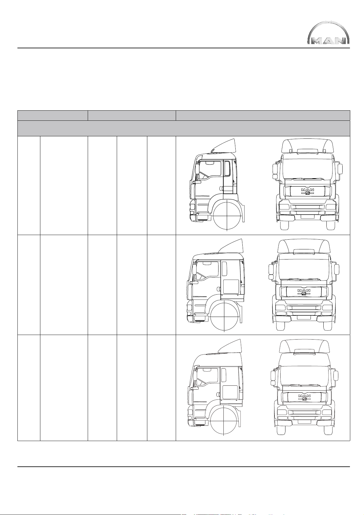
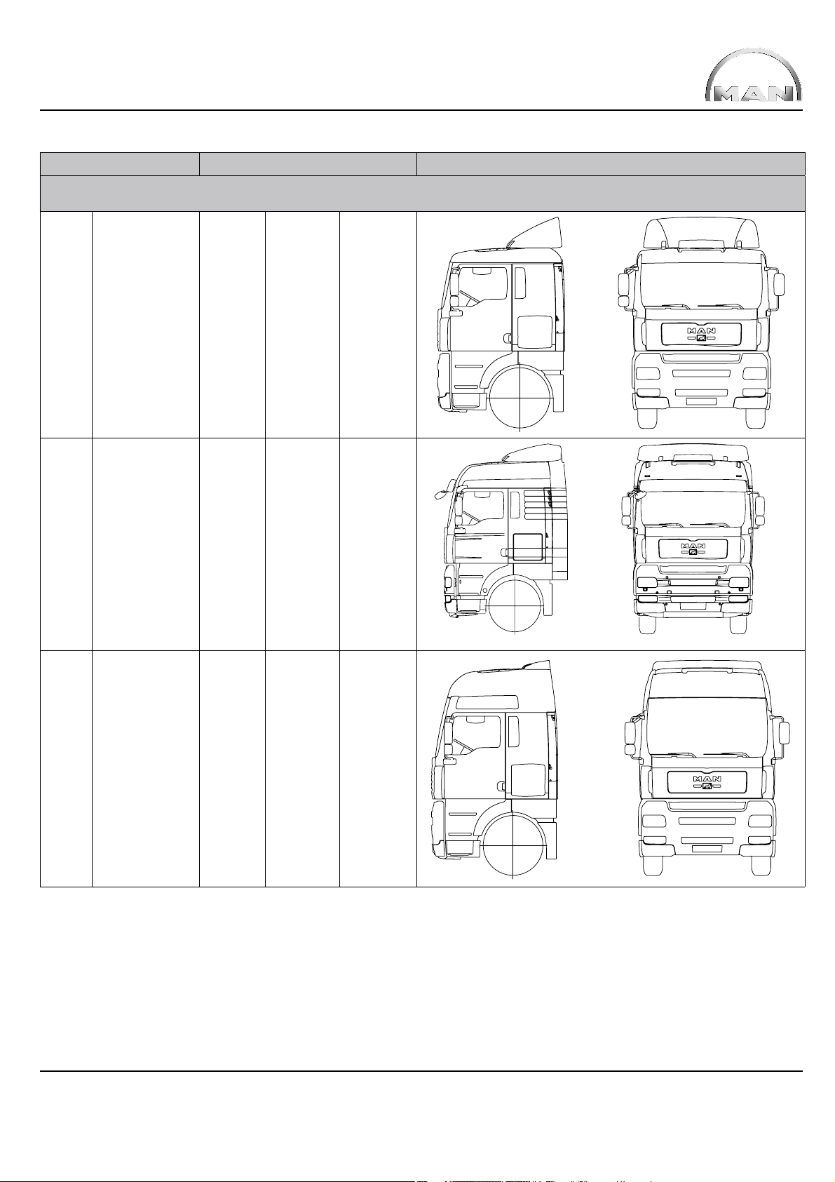
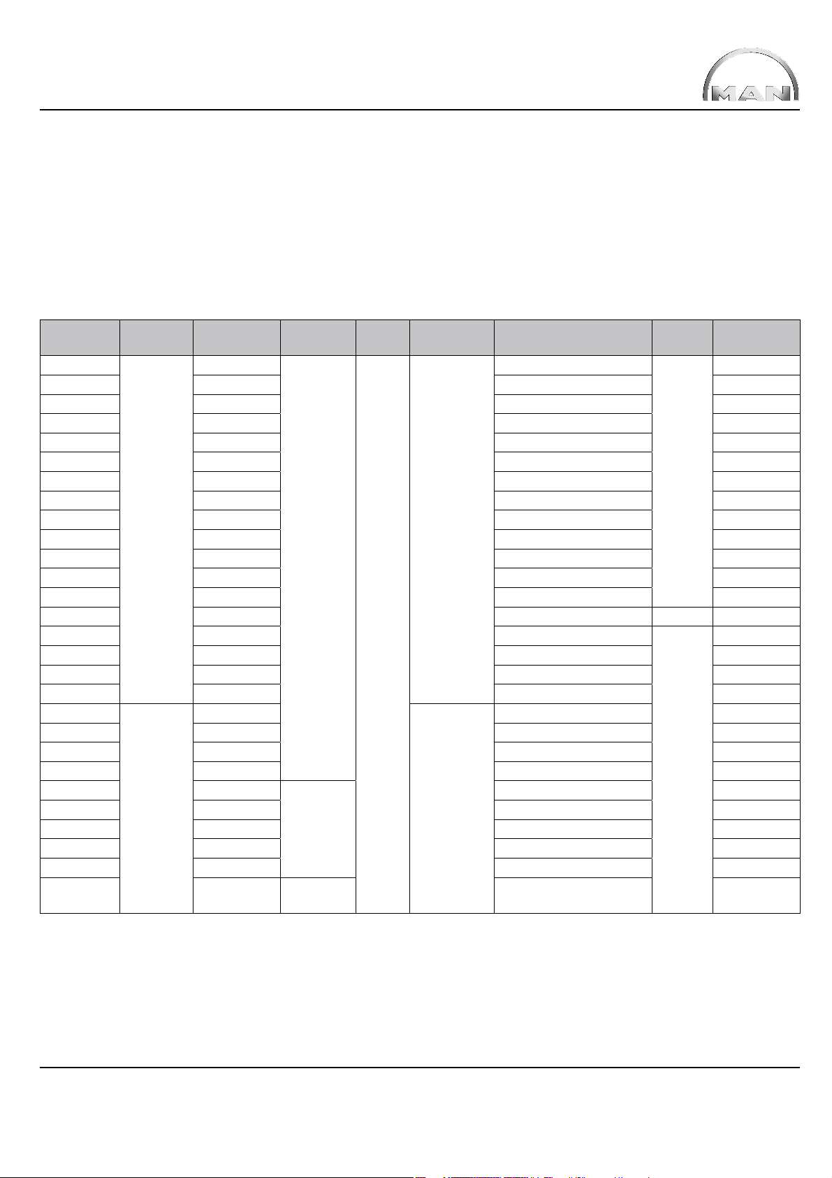
2.4 Cabs
There are 6 different Trucknology® Generation A cabs:
®
Table 7: Trucknology
Description Dimensions* Views
Name Technical Length Width High roof Side Front
description
M LHD
F99L15S
RHD
F99R15S
Generation A cabs
1.880 2.240
L LHD
F99L32S
RHD
F99R32S
LX LHD
F99L37S
RHD
F99R37S
2.280 2.240
2.280 2.240 yes
*) Dimensions refer to the cab without attachments such as mudguards, front spoiler, mirrors, roof spoiler etc.
TRUCKNOLOGY® GENERATION A (TGA) 19
Description Dimensions* Views
Name Technical Length Width High roof Side Front
description
XL LHD
F99L40S
RHD
F99R40S
2.280 2.440
XLX LHD
F99 L47 S
RHD
F99 R47 S
XXL LHD
F99L41S
RHD
F99R41S
2.280 2.440 yes, low
2.280 2.440 yes
*) Dimensions refer to the cab without attachments such as mudguards, front spoiler, mirrors, roof spoiler etc.
TRUCKNOLOGY® GENERATION A (TGA) 20
2.5 Engine variants
In-line six-cylinder Diesel engines (R6) and a V10 with 4-valve technology from the D28 family of engines are installed in the TGA
(D28 = 1st – 3rd digits of the engine designation). Engines with common rail injection are new additions to the range.
The engine programme has been extended since 2004 with two further engine ranges – the well known engines from the D08 range and
the new D20 Common Rail range that are also available as Euro 4 engines with the PM-Kat
only installed in ERF brand trucks (see table 6, model numbers).
Table 8: TGA engines/engine designations D08D08 / D20 / D26 / D28
®
. Cummins engines of the ISMe range are
Vehicle
designation
xx.280
xx.330 240 kW / 2.400 1.250 at 1.200 - 1.800 rpm D0836LF44
xx.310 228 kW / 1.900 1.500 at 900 - 1.300 rpm D2866LF26
xx.310 228 kW / 1.900 1.550 at 1.000 - 1.300 rpm D2066LF04
xx.360 265 kW / 1.900 1.700 at 900 - 1.400 rpm D2866LF27
xx.350 257 kW / 1.900 1.750 at 1.000 - 1.300 rpm D2066LF03
xx.410 301 kW / 1.900 1.850 at 900 - 1.300 rpm D2866LF28
xx.390 287 kW / 1.900 1.900 at 1.000 - 1.300 rpm D2066LF02
xx.430 316 kW / 1.900 2.100 at 1.000 - 1.300 rpm D2066LF01
xx.460 338 kW / 1.900 2.100 at 900 - 1.300 rpm D2876LF04
xx.510 375 kW / 1.900 2.300 at 1.000 - 1.300 rpm D2876LF05
xx.480 353 kW / 1.900 2.300 at 1.000 - 1.400 rpm D2876LF12
xx.530 390 kW / 1.900 2.400 at 1.000 - 1.400 rpm D2876LF13
xx.660 485 kW / 1.900 2.700 at 1.000 - 1.600 rpm V10 D2840LF25
xx.360 265 kW / 1.900 1.800 at 1.000 - 1.400 rpm
xx.400 294 kW / 1.900 1.900 at 1.000 - 1.400 rpm D2066LF49
xx.440 324 kW / 1.900 2.100 at 1.000 - 1.400 rpm D2066LF50
xx.480 353 kW / 1.900 2.300 at 1.050 - 1.400 rpm D2676LF31
xx.310
xx.350 257 kW / 1.900 1.750 at 1.000 - 1.400 rpm D2066LF13
xx.390 287 kW / 1.900 1.900 at 1.000 - 1.400 rpm D2066LF12
xx.430 316 kW / 1.900 2.100 at 1.000 - 1.400 rpm D2066LF11
xx.320 235 kW / 1.900
xx.360 265 kW / 1.900 1.800 at 1.000 - 1.400 rpm D2066LF33
xx.400 294 kW / 1.900 1.900 at 1.000 - 1.400 rpm D2066LF32
xx.440 324 kW / 1.900 2.100 at 1.000 - 1.400 rpm D2066LF31
xx.480 353 kW / 1.900 2.300 at 1.050 - 1.400 rpm D2676LF01
xx.320 235 kW / 1.900 OBD 1 +
Emission
class
Euro 3
Euro 4
Power [kW]
at [rpm]
206 kW / 2.400
228 kW / 1.900
OBD
generation
No OBD
OBD 1
control
NO
X
EGR Exhaust gas
after treatment
None
With
AGR
®
PM-Kat
Max. torque
[Nm] / at [rpm]
1.100 at 1.200 - 1.800 rpm
1.550 at 1.000 - 1.400 rpm D2066LF14
1.600 at 1.000 - 1.400 rpm D2066LF35
1.600 at 1.000 - 1.400 rpm D2066LF39
Engine
type
R6
R6
Engine
designation
D0836LF41
D2066LF48
TRUCKNOLOGY® GENERATION A (TGA) 21

Vehicle
designation
xx.360 Euro 4 265 kW / 1.900 OBD 1 +
xx.400 294 kW / 1.900 1.900 at 1.000 - 1.400 rpm D2066LF37
xx.440 324 kW / 1.900 2.100 at 1.000 - 1.400 rpm D2066LF36
xx.480 353 kW / 1.9 00 2.300 at 1.050 - 1.400 rpm D2676LF05
xx.400
xx.440 321 kW / 1.900 2.100 at 1.000 - 1.400 rpm D2066LF21
xx.400 294 kW / 1.900
xx.440 324 kW / 1.900 2.100 at 1.000 - 1.400 rpm D2066LF23
xx.480 353 kW / 1.9 00 2.300 at 1.050 - 1.400 rpm D2676LF12
xx.5 40 397 kW / 1.900 2.500 at 1.050 - 1.350 rpm D2676LF11
xx.320 235 kW / 1.900
xx.360 265 kW / 1.900 1.800 at 1.000 - 1.400 rpm D2066LF27
xx.400 294 kW / 1.900 1.900 at 1.000 - 1.400 rpm D2066LF26
xx.440 324 kW / 1.900 2.100 at 1.000 - 1.400 rpm D2066LF25
xx.480 353 kW / 1.900 2.300 at 1.050 - 1.400 rpm D2676LF14
xx.5 40 397 kW / 1.900 2.500 at 1.050 - 1.350 rpm D2676LF13
xx.320* 235 kW / 1.900 1.600 at 1.000 - 1.400 rpm D2066LF20
xx.360* 265 kW / 1.900 1.800 at 1.000 - 1.400 rpm D2066LF19
xx.400* 294 kW / 1.900 1.900 at 1.000 - 1.400 rpm D2066LF18
xx.440* 324 kW / 1.900 2.100 at 1.000 - 1.400 rpm D2066LF17
xx.480* 353 kW / 1.900 2.300 at 1.050 - 1.400 rpm D2676LF16
xx.540* 397 kW / 1.900 2.500 at 1.050 - 1.350 rpm D2676LF15
* = In case of NO
rescue services and military vehicles in accordance with Annex I.6558 of Directive 2005/55/EC, version 2006/81/EC
Emission
class
Euro 5
system failure, engines fi tted with OBD 1b or OBD 2 are without torque reduction (TR). Only applies to engines for fi re services,
X
Power [kW]
at [rpm]
294 kW / 1.900
OBD
generation
NOX control
NO OBD
OBD 1
OBD 1 +
NO
control
X
EGR Exhaust gas
after treatment
With
EGR
No
EGR
PM-Kat
SCR
®
Max. torque
[Nm] / at [rpm]
1.800 at 1.000 - 1.400 rpm
1.900 at 1.000 - 1.400 rpm D2066LF22
1.900 at 1.000 - 1.400 rpm D2066LF24
1.600 at 1.000 - 1.400 rpm D2066LF28
Engine
type
R6
Engine
designation
D2066LF38
3. General
National and international regulations take priority over technically permissible dimensions and weights if they limit the technically
permissible dimensions and weights. The following data can be obtained from the quotation documents and documents contained in
MANTED® at www.manted.de:
• Dimensions
• Weights
• Centre of gravity position for payload and body (minimum and maximum position for body) for the production standard
chassis / tractor unit.
The data contained in these documents may vary depending on what technical features the vehicle is actually fi tted with upon delivery.
The critical factor is the vehicle’s actual confi guration and condition at the time delivery.
To achieve optimum payload carrying capability the chassis must be weighed before work starts on the body.
Calculations can then be made to determine the best centre of gravity position for payload and body as well as the optimum body
length. As a result of component tolerances the weight of the standard chassis is allowed to vary by ± 5%, in accordance with
DIN 70020. Any deviations from the standard equipment level will have a greater or lesser effect on dimensions and weights.
Changes in equipment may result in deviations in the dimensions and weights, particularly if different tyres are fi tted that then also lead
to a change in the permissible loads.
TRUCKNOLOGY® GENERATION A (TGA) 22
In each individual case when a body is fi tted care needs to be taken to ensure the following
• Under no circumstances may the permissible axle weights be exceeded
• A suffi cient minimum front axle load is achieved
• The position of the centre of gravity and loading must not be one-sided
• The permissible overhang (vehicle overhang) is not exceeded.
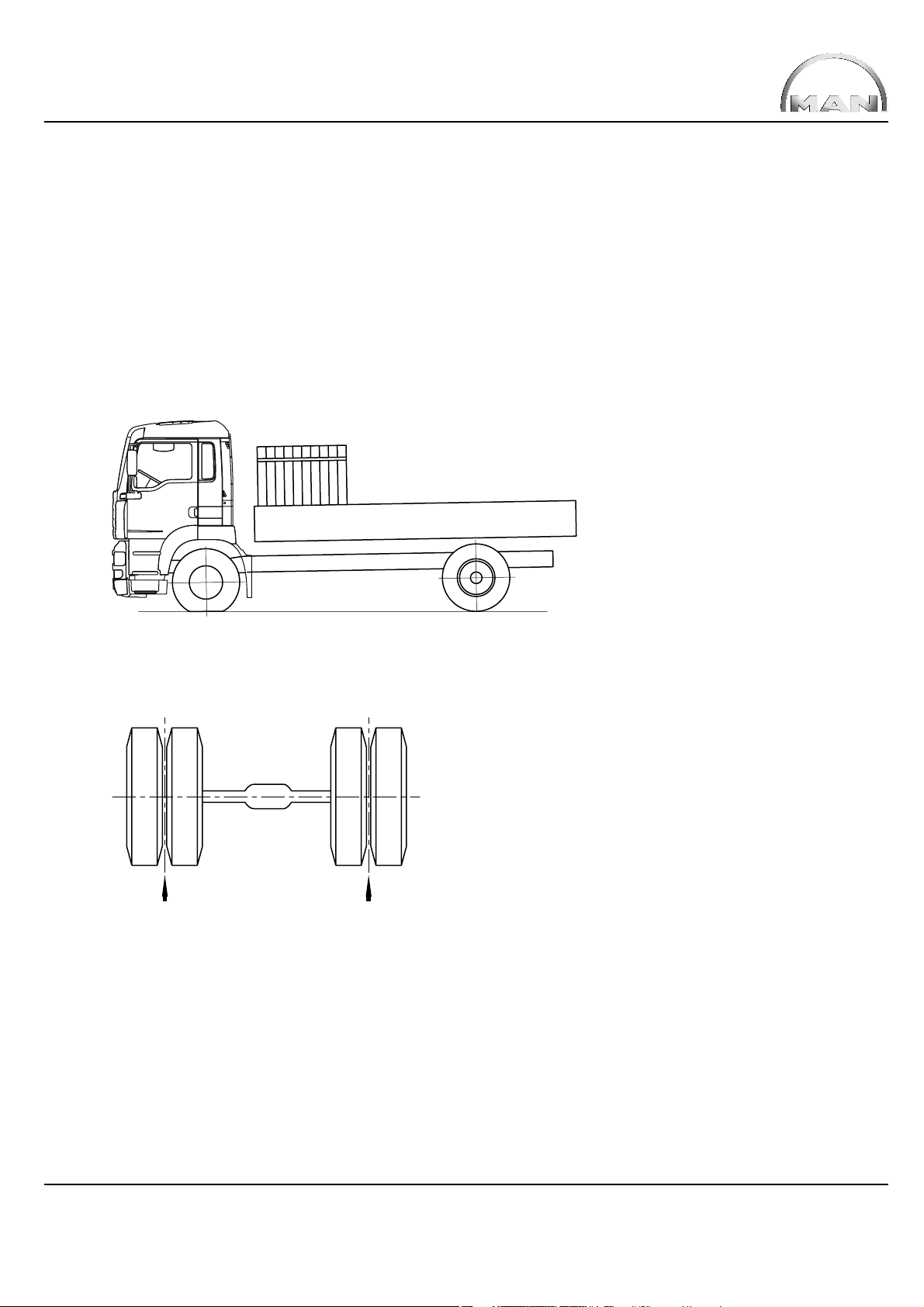
3.1 Axle overload, one-sided loading
Fig. 1: Overloading the front axle ESC-052
Fig. 2: Difference in wheel load ESC-126
G G
Formula 1: Difference in wheel load
∆G ≤ 0,05 • G
tat
The body must be designed such that one-sided wheel loads do not occur. Following checks, a maximum wheel load difference of 5 %
is permitted (where 100 % represents the actual axle load and not the permissible axle load).
TRUCKNOLOGY® GENERATION A (TGA) 23
 Loading...