


K
Electrical system
Trucknology Generation A (TG-A)
2002 |
1 | 2 |
3 |
4 | 5 | 6 | 7 | 8 | 9 | 10 | 11 | 12 |
|
|
|
|
Publication no.:
81.99198-5972
Wiring diagrams
2nd Edition K 90
MAN Nutzfahrzeuge Aktiengesellschaft |
Elektrische Anlage TG-A |
|
Dachauer Str. 667 |
oder Postfach 50 06 20 |
Schaltpläne K 90 (2. Ausgabe) |
80995 MÜNCHEN |
80976 MÜNCHEN |
– englisch – |
|
|
Printed in Germany |
Electrical system
Wiring diagrams K 90 (2nd edition)
Trucknology Generation A (TG-A)
81.99198-5972

ELECTRICAL SYSTEM
Subject to technical changes in the course of continuing development.
1999 MAN Nutzfahrzeuge Aktiengesellschaft
Reprinting, duplication or translation are not permitted without written consent from MAN. MAN Nutzfahrzeuge AG specifically reserves all rights conferred by law concerning copyright.
VSWY / OB/AM 03.2002 |
Satz: emes GmbH |
|
Friedrichshafen |
0.01 - 2 |
K 90 |

ELECTRICAL SYSTEM
Preface
All series and additional wiring diagrams are documented in the instructions for the “wiring diagrams” .
The series wiring diagrams (Ch. 3.00) and the additional wiring diagrams (Ch. 4.00) are shown in detail to include legends and the names of the circuits.
The present manual is based on wiring diagrams that have been created with the help of a graphics program (CAD).
This allows the instructions to be updated at short notice.
This manual represents the series status of the vehicle on the copy deadline date.
K 90 |
0.10 - 1 |

ELECTRICAL SYSTEM
Contents |
|
Electrical system ........................................................................................................................... |
0 |
Preface.......................................................................................................................................... |
0.10 - 1 |
Contents........................................................................................................................................ |
0.11 - 1 |
Abbreviations ................................................................................................................................ |
0.13 - 1 |
General remarks ............................................................................................................................ |
1 |
Safety notes .................................................................................................................................. |
1.20 - 1 |
Instructions for the use of wiring diagrams ................................................................................... |
1.60 - 1 |
Search criteria ............................................................................................................................... |
1.99 - 1 |
Series wiring diagrams ................................................................................................................. |
3 |
Contents........................................................................................................................................ |
3.00 - 1 |
Additional wiring diagrams .......................................................................................................... |
4 |
Contents........................................................................................................................................ |
4.00 - 1 |
K 90 |
0.11 - 1 |

ELECTRICAL SYSTEM
Abbreviations |
As of: 11.01 |
|
a |
Acceleration |
|
ABE |
General operating permit |
|
ABS |
Anti-lock brake system |
|
ABV |
Anti-skid system |
|
AC |
Air conditioning |
|
ACC |
Adaptive cruise control |
|
ACK |
Autocheck |
|
ADC |
Analog-digital converter |
|
ADR |
International agreement for the transport of dangerous goods |
|
AGB |
Automatic road speed limiter |
|
AGND |
Analog ground |
|
AGR |
Exhaust gas recirculation (EGR) |
|
AHK |
Trailer coupling |
|
AHV |
Trailer brake valve |
|
ALB |
Automatic load-dependent brake |
|
AMA |
Antenna mast system |
|
ANH |
Trailer/semitrailer |
|
AS |
Automated gearbox |
|
ASD |
Trailer socket |
|
ASM |
Trailer control module |
|
ASR |
Anti-spin regulator |
|
ASV |
Trailer control valve |
|
ATC |
Automatic temperature control |
|
ATF |
Automatic transmission fluid |
|
AU |
Emission test |
|
AV |
Exhaust valve |
|
AVS |
Automatic gear preselection |
|
BA |
Operator's manual |
|
BBA |
Service brake system |
|
BBV |
Service brake valve |
|
BKR |
Brake power regulator |
|
BUGH |
Front heater |
|
BV |
Back-up valve |
|
BVA |
Brake wear indicator |
|
BVS |
Brake wear sensor |
|
BVV |
Brake wear sensor supply |
|
BW |
German Army |
|
BWG |
Brake value sensor |
|
BZ |
Brake cylinder |
|
CAN |
Controller area network |
|
CAN-H |
CAN-high data line |
|
CAN-L |
CAN-low data line |
|
CATS |
Computer-assisted testing and diagnostic system |
|
CCVS |
Cruise control vehicle speed |
|
CKD |
Completely knocked down |
|
CNG |
Compressed natural gas |
|
CPU |
Central processing unit |
|
CRT |
Continuously regenerating trap |
|
CS |
Comfort shift |
|
DAHL |
Roof ventilator |
|
DBR |
Auxiliary brake relay |
|
DECKE |
Cover (for doors) |
|
DF |
Speed sensor |
|
DFÜ |
Data transmission |
|
DIA |
Diagnosis and information display |
|
K 90 |
0.13 - 1 |

ELECTRICAL SYSTEM
Abbreviations
DIAK |
Diagnosis, K-line (data line) |
DIAL |
Diagnosis, L-line (interrogation line) |
DIAR |
Diagnosis, further interrogation |
DIN |
German industrial standard |
DKE |
Throttle valve increase (ASR control) |
DKH |
Roof duct heating |
DKL |
Roof flaps |
DKR |
Throttle valve reduction (reduction request from ASR to EDC/EMS) |
DKV |
Throttle valve specification (load sensor signal from EDC/EMS pedal value sensor) |
DLB |
Compressed air brake system |
DM |
Diagnostic message |
DNR |
Drive – Neutral – Reverse (selector switch for automatic gearbox) |
DPF |
Diesel particulate filter |
DRM |
Pressure control module |
DS |
Pressure sensor |
DSV |
Pressure control valve |
DV |
Throttle valve |
DWA |
Anti-theft protection system |
DZG |
Rpm sensor |
DZM |
Rev counter |
EBS |
Electronic brake system |
ECAM |
Electronically controlled air management |
ECAS |
Electronically controlled air suspension |
ECE |
Emergency shut-off to ECE 36 |
ECU |
Electronic control unit |
EDC |
Electronic diesel control |
EDM |
Electronic diesel consumption meter |
EDR |
Maximum speed governor |
EEC |
Electronic engine controller |
EEPROM |
Electrically erasable and programmable read-only memory |
EFR |
Electronic shock absorber control (ESAC) |
EFS |
Electrical driver's seat |
EHAB |
Electro-hydraulic shut-off device |
ELAB |
Electrical shut-off device |
ELF |
Electronic air suspension |
EMS |
Electronic throttle control (ETC) |
EMV |
Electromagnetic compatibility (EMC) |
EOL |
End-of-line (programming) |
EP |
Injection pump |
ER |
Engine retarder (engine brake) |
ESAC |
Electronic shock absorber control |
ESP |
Electronic stability program |
ESR |
Electric sun-blind |
EST |
Electronic control unit |
EV |
Intake valve |
EVB |
Exhaust valve brake |
FAP |
Driver's area |
FAQ |
Frequently asked questions |
FBA |
Parking brake system |
FDR |
Dynamic handling control |
FFR |
Vehicle management computer (VMC) |
FGB |
Road speed limiter (RSL) |
FGR |
Road speed governor (RSG) |
FHS |
Cab |
FIN |
Vehicle identification number (VIN) |
FM |
Vehicle management |
FMI |
Failure mode identification |
0.13 - 2 |
K 90 |

ELECTRICAL SYSTEM
Abbreviations
FMR |
Vehicle/engine management |
FOC |
Front omnibus chassis (bus/coach chassis with front-mounted engine) |
FSCH |
Windscreen heater |
FSG |
Ground reinforcement system |
FSH |
Window/mirror heating |
FTW |
Driver's partition |
FUNK |
Radio communication unit |
FZA |
Destination system |
GDK |
Controlled diesel catalytic converter |
GEN |
Alternator |
GET |
Gearbox |
GGVS |
Regulations for the transport of hazardous goods |
GND |
Ground |
GP |
Gearbox planetary gear group (range-change box) |
GS |
Gearbox control |
GV |
Gearbox splitter gear group (splitter box) |
HA |
Rear axle |
HBA |
Auxiliary brake system |
HGB |
Maximum road speed limiter |
HGS |
Hydraulic gearshift |
HLUE |
Hydrostatic fan |
HOC |
Rear omnibus chassis (bus/coach chassis with rear-mounted engine) |
HSS |
Highside switch |
HST |
Main control panel |
HU |
Main inspection |
Hz |
Hertz (number of cycles per second) |
HZA |
Bus stop indicator system |
HZG |
Auxiliary rpm sensor |
IBEL |
Interior lighting |
IBIS |
Integrated on-board information system |
IC |
Integrated circuit |
ID |
Identification |
IMR |
Integrated mechanical relay (starter control) |
INA |
Information indicator (e.g. check lamp) |
IR |
Individual control (ABS) |
IRM |
Modified individual control (ABS) |
ISO |
International Standards Organisation |
IWZ |
Incremental angle/time measuring system |
KBZ |
Combination brake cylinder |
KFH |
Fuel filter heater |
KITAS |
Kienzle intelligent tachograph sensor |
KLI |
Air-conditioning system |
KNEEL |
Kneeling |
KSM |
Customer-specified control module |
KSW |
Customer’s special request |
KWP |
Key word protocol (protocol for MAN-cats diagnosis) |
LBH |
Air reservoir |
LCD |
Liquid crystal display |
LDA |
Manifold-pressure compensator (boost control) |
LDF |
Boost pressure sensor |
LDS |
Air spring/damper system |
LED |
Light emitting diode |
LF |
Air suspension |
LGS |
Lane guard system |
K 90 |
0.13 - 3 |

ELECTRICAL SYSTEM
Abbreviations
LL |
Idling speed |
LLA |
Idling speed increase |
LLR |
Idling speed control |
LNG |
Liquified natural gas |
LOE |
Steering oil monitor |
LPG |
Liquified petroleum gas |
LWR |
Headlight beam regulator |
M-TCO |
Modular EU tachograph |
MAB |
Solenoid valve shut-off (engine shut-off by means of high-pressure solenoid valve in injection |
|
pump) |
MAN-cats MAN computer assisted testing and diagnostic system) |
|
MAR |
Solenoid valve shut-off relay (redundant engine shut-off relay) |
MDB |
Engine speed range |
MES |
Fuel metering control |
ML |
Midline |
MMI |
Man-machine interface |
MOTB |
Engine brake |
MP |
Engine power box (cable duct on engine block) |
MR |
Engine governor – ASR |
MSG |
Engine control unit (EDC) |
MV |
Solenoid valve |
MZ |
Diaphragm cylinder |
n |
rpm |
NA |
Power take-off (PTO) |
NBF |
Needle movement sensor |
NES |
New electronic structure |
NFZ |
Commercial vehicle |
NLA |
Trailing axle |
NSL |
Rear fog lamp |
NSW |
Front fog lamp |
OBDU |
On-board diagnostic unit |
OC |
Occurrence count (errors/faults) |
OEAB |
Oil separator |
OENF |
Oil top-up |
p |
Pressure |
PBM |
Pulse breadth modulation ( also see PWM) |
PLM |
Programmable logic module |
PSG |
Pump control unit (EDC) |
PTO |
Power take-off |
PWM |
Pulse width modulation ( also see PBM) |
RA |
Repair manual |
RAH |
Interior heating |
RAM |
Random access memory |
RAS |
Rear axle steering |
RAS-EC |
Rear axle steering with electronic control |
RDRA |
Tyre pressure control system |
RDS |
Radio data system |
RET |
Retarder |
RKL |
Priority vehicle light |
RLV |
Relay valve |
RME |
Rape seed oil methyl ester (biodiesel) |
ROM |
Read only memory |
0.13 - 4 |
K 90 |

ELECTRICAL SYSTEM
Abbreviations
SA |
Special equipment |
|
SAE |
Society of Automotive Engineers |
|
SAMT |
Semi-automatic mechanical transmission |
|
SB |
Service outlet |
|
sec |
Second |
|
SER |
Series (production) |
|
SG |
Control unit |
|
SH |
Select-high control (ABS) |
|
SKD |
Semi-knocked down |
|
SL |
Select-low control (ABS) |
|
SML |
Side marker light |
|
SPN |
Suspect parameter number |
|
STA |
Engine start/stop |
|
SWR |
Headlight cleaning system |
|
t |
Time |
|
TC |
Traction control |
|
TCM |
Trailer control module |
|
TCO |
Tachograph |
|
TKU |
Technical customer document |
|
TMC |
Traffic message channel |
|
TRS |
Technical road transport directives |
|
TSC |
Torque speed control (braking torque) |
|
TUER |
Door control |
|
UBat |
Battery voltage |
|
UDS |
Crash recorder |
|
v |
Velocity/vehicle speed |
|
VA |
Front axle |
|
VG |
Transfer case |
|
VLA |
Leading axle |
|
WA |
Maintenance manual |
|
WAB |
Water separator |
|
WLE |
Swap-body unit |
|
WR |
Warning relay |
|
WS |
Position sensor |
|
WSK |
Torque converter and clutch unit |
|
z |
Braking rate/deceleration |
|
ZBR |
Central on-board computer |
|
ZBRO |
Central on-board bus computer |
|
ZDR |
Intermediate speed governor (ISG) |
|
ZE |
Central electrical system (CES) |
|
ZR |
Central computer |
|
ZS |
Central lubrication |
|
ZUSH |
Auxiliary heater |
|
ZWS |
Time-based maintenance system |
|
λ |
Slipµ |
Coefficient of friction |
µC |
Microcontroller (microprocessor) |
|
K 90 |
0.13 - 5 |
GENERAL INFORMATION
Notes on safety
The following sections include summaries of important regulations listed according to major topics. The intention is to provide the knowledge needed to avoid accidents which could lead to injury, damage and environmental pollution.
Additional instructions are included in the Operator's Manual that is provided with the vehicle.
Important:
Accidents may happen in spite of all precautionary measures having been taken. In such an eventuality, obtain immediate medical assistance from a doctor. This is particularly important if the accident involves skin contact with corrosive acid, fuel penetration under the skin, scalding by hot oil, antifreeze spraying into eyes etc.
Regulations for preventing accidents leading to injury to personnel.
Only authorised technical personnel are allowed to perform inspection, adjustment and repair work.
∙ Secure the vehicle to prevent it from rolling away.
Support the frame when working on the pneumatic or spring suspension system.
∙Secure units during their removal.
∙Only authorised personnel are allowed to start and operate the engine.
∙Do not approach moving parts of a running engine too closely. Do not wear baggy clothing.
∙Do not touch the engine with your bare hands when it is at operating temperature: Risk of burns!
∙ Keep the area around the engine, ladders and steps free from oil and grease. Accidents caused by slipping can have serious consequences.
∙ Only use tools that are in perfect condition. Damaged or widened spanners can slip: Risk of injury!
∙No-one is allowed to stand under an engine suspended from a crane hook.
– Keep all lifting tackle in good condition –.
∙Collect any brake fluid that emerges. Treat brake fluid as hazardous waste! Comply with the safety regulations for preventing environmental pollution.
∙ Brake fluid is toxic! Do not allow it to come into contact with food or open wounds.
∙Do not open the coolant circuit until the engine has cooled down. If it does need to be opened whilst the engine is at operating temperature, follow the instructions in the “Maintenance and care” section in the Operator's Manual.
∙Do not attempt to retighten or open pipe lines and hoses (lubricating oil circuit, coolant circuit and possible subsequent hydraulic oil circuit) whilst they are pressurised: Fluid spraying out represents an injury hazard!
∙Do not hold your hands under the jet of fuel when checking the injector nozzles. Do not inhale fuel vapours.
K 90 |
1.20 - 1 |
GENERAL INFORMATION
∙ Always disconnect the batteries before working on the vehicle electrical system.
Important! Oxyhydrogen gas may form in enclosed battery boxes. When the batteries are disconnected, this gas may be ignited by sparks produced by other continuously operating consumers, the tachograph etc. that cannot be shut down. Blow compressed air through the battery box before disconnecting the batteries!
∙Only tow-start the vehicle if the batteries are connected (minimum charge 40%)! Do not use a boost-charger to jump-start the vehicle! Always disconnect the positive and negative leads before boost-charging batteries!
∙Disconnect the batteries and recharge them every 4 weeks if the vehicle is not in use.
Caution! Battery acid is poisonous and corrosive. Battery gases are explosive.
∙Follow the manufacturer’s instructions for handling batteries.
∙Measure voltage only using suitable measuring devices!
The input resistance of a measuring device should be at least 10 MΩ.
∙The ignition must be switched off before the wiring harness plugs of electronic control units are disconnected or connected up!
When performing electrical welding work, connect up the “ANTIZAP SERVICE MONITOR” (MAN item number 80.78010.0001) or the improved SES-1 version (MAN item number 80.78010.0002) in accordance with the instructions supplied with the device.
If this device is not available, disconnect the batteries and join the positive cable to the negative cable in order to make a conductive connection.
Always earth the welding equipment as close as possible to the welding area. Do not lay the cables to the welding equipment in parallel to electrical cables in the vehicle.
For further accident prevention measures, please refer to the “Leaflets for welders”.
The frame is not intended for use as an earth return!
∙If attachments are to be retrofitted to the vehicle – e.g. a taillift – additional earth lines with adequate cross-section must be fitted as well. Otherwise the earth connection may be created along wire cables, wiring harnesses, gearbox shafts, gears etc. Severe damage could result.
∙If painting work is to be carried out, do not expose the electronic components to high temperatures (max. 95 °C) for more than bri ef periods; a time of up to around 2 hours is permissible at a maximum of 85 °C . Disconnect the batteries.
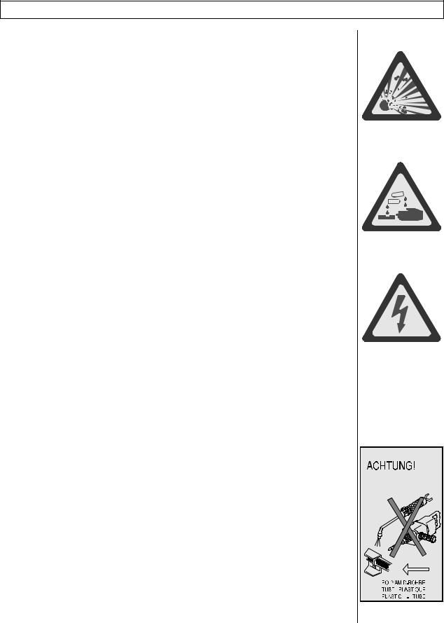
Plastic tubes (polyamide)
Important! – Risk of damage and fire!
∙The warning sign opposite can be found on the co-driver's door below the door lock. It warns you against welding or drilling near to plastic tubes.
1.20 - 2 |
K 90 |
|
|
|
|
|
|
|
|
||
|
|
|
|
||
|
|
|
|
||
|
|
|
|
||
|
|
|
|

GENERAL INFORMATION
Limited liability for accessories and parts
In your own interests, you are recommended to use only accessories expressly approved by MAN and genuine MAN parts for your MAN vehicle. The reliability, safety and suitability of these parts and accessories have been determined specifically for MAN vehicles. Despite constant market observation, we cannot judge the aspects of other products, nor can we accept responsibility for them – even if they have been officially approved by the German TÜV technica l inspection authorities or some other official body.
Bodies and special attachments
Comply with the safety instructions and regulations issued by the bodymaker in question if bodies or special attachments are fitted.
Taking out of operation or putting into storage
The special measures described in MAN Works Standard M 3069 Part 3 apply if buses or trucks are to be withdrawn from service or stored for a period longer than 3 months.
K 90 |
1.20 - 3 |

GENERAL REMARKS
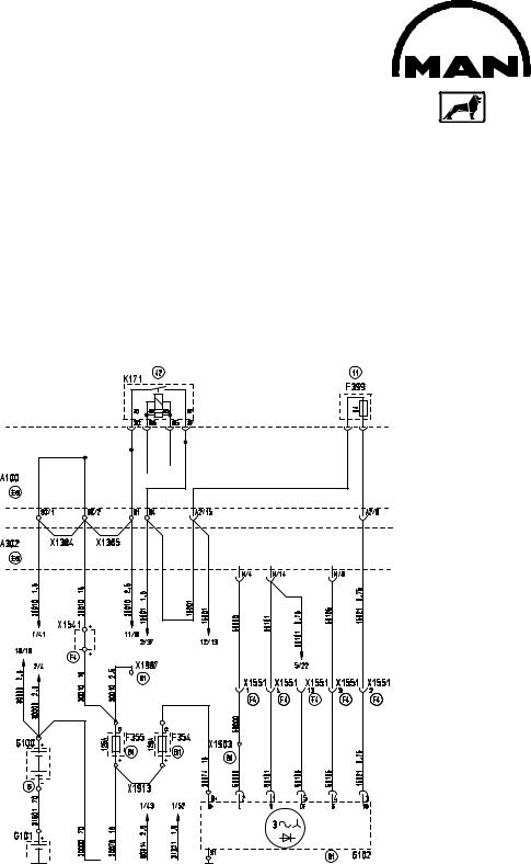
Instructions for using wiring diagrams
1Name of component (here: diode V100 on the central fuse, relay and terminal box (“ZE”), position 53)
2Mounting position on the front panel of the central fuse, relay and terminal box (“ZE”) (here: engraved position number 53)
3Plug connector on the rear of the central fuse, relay and terminal box (“ZE”) (here: plug 78, connection 8)
4Cable number; printed on the cable at short intervals (cross-section only if greater than 12)
5Sheet number (not page number) and circuit number
Marking to show on which sheet and circuit the conductor continues (here: continuation of conductor 31002 on sheet 2 on circuit 4)
6Plug connector (here: single-pin connector X104 in the ZE area)
7Component mounting position (here: 21-pin connector X238 Pin R
– wiring harness cab to engine – in central portion)
8Circuit number (please note: sheets are numbered consecutively from 1 to 55)
Important note on the use of the wiring diagram legends: A three-digit number is shown in brackets after various item numbers. This number is the coded part number for this component!
These part numbers can be found in the T60 device list.
K 90 |
1.60 - 1 |
GENERAL REMARKS
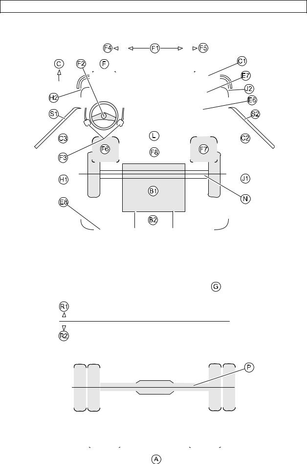
Mounting positions for left-hand drive
|
|
|
|
|
|
|
|
|
|
|
|
|
|
|
|
|
|
|
|
|
|
|
|
|
|
|
|
|
|
|
|
|
|
|
|
|
|
|
|
|
|
|
|
|
|
|
|
|
|
|
|
|
|
|
|
|
|
|
|
|
|
|
|
|
|
|
|
|
|
|
|
|
|
|
|
|
|
|
|
|
|
|
|
|
|
|
|
|
|
|
|
|
|
|
|
|
|
|
|
|
|
|
|
|
|
|
|
|
|
|
|
|
|
|
|
|
|
|
|
|
|
|
|
|
|
|
|
|
|
|
|
|
|
|
|
|
|
|
|
|
|
|
|
|
|
|
|
|
|
|
|
|
|
|
|
|
|
|
|
|
|
|
|
|
|
|
|
|
|
|
|
|
|
|
|
|
|
|
|
|
|
|
|
|
|
|
|
|
|
|
|
|
|
|
|
|
|
|
|
|
|
|
|
|
|
|
|
|
|
|
|
|
|
|
|
|
|
|
|
|
|
|
|
|
|
|
|
|
|
|
|
|
|
|
|
|
|
|
|
|
|
|
|
|
|
|
|
|
|
|
|
|
|
|
|
|
|
|
|
|
|
|
|
|
|
|
|
|
|
|
|
|
|
|
|
|
|
|
|
|
|
|
|
|
|
|
|
|
|
|
|
|
|
|
|
|
|
|
|
|
|
|
|
|
|
|
|
|
|
|
|
|
|
|
|
|
|
|
|
|
|
|
|
|
|
|
|
|
|
|
|
|
|
|
|
|
|
|
|
|
|
|
|
|
|
|
|
|
|
|
|
|
|
|
|
|
|
|
|
|
|
|
|
|
|
|
|
|
|
|
|
|
|
|
|
|
|
|
|
|
|
|
|
|
|
|
|
|
|
|
|
|
|
|
|
|
|
|
|
|
|
|
|
|
|
|
|
|
|
|
|
|
|
|
|
|
|
|
|
|
|
|
|
|
|
|
|
|
|
|
|
|
|
|
|
|
|
|
|
|
|
|
|
|
|
|
|
|
|
|
|
|
|
|
|
|
|
|
|
|
|
|
|
|
|
|
|
|
|
|
|
|
|
|
|
|
|
|
|
|
|
|
|
|
|
|
|
|
|
|
|
|
|
|
|
|
|
|
|
|
|
|
|
|
|
|
|
|
|
|
|
|
|
|
|
|
|
|
|
|
|
|
|
|
|
|
|
|
|
|
|
|
|
|
|
|
|
|
|
|
|
|
|
|
|
|
|
|
|
|
|
|
|
|
|
|
|
|
|
|
|
|
|
|
|
|
|
|
|
|
|
|
|
|
|
|
|
|
|
|
|
|
|
|
|
|
|
|
|
|
|
|
|
|
|
|
|
|
|
|
|
|
|
|
|
|
|
|
|
|
|
|
|
|
|
|
|
|
|
|
|
|
|
|
|
|
|
|
|
|
|
|
|
|
|
|
|
|
|
|
|
|
|
|
|
|
|
|
|
|
|
|
|
|
|
|
|
|
|
|
|
|
|
|
|
|
|
|
|
|
|
|
|
|
|
|
|
|
|
|
|
|
|
|
|
|
|
|
|
|
|
|
|
|
|
|
|
|
|
|
|
|
|
|
|
|
|
|
|
|
|
|
|
|
|
|
|
|
|
|
|
|
|
|
|
|
|
|
|
|
|
|
|
|
|
|
|
|
|
|
|
|
|
|
|
|
|
|
|
|
|
|
|
|
|
|
|
|
|
|
|
|
|
|
|
|
|
|
|
|
|
|
|
|
|
|
|
|
|
|
|
|
|
|
|
|
|
|
|
|
|
|
|
|
|
|
|
|
|
|
|
|
|
|
|
|
|
|
|
|
|
|
|
|
|
|
|
|
|
|
|
|
|
|
|
|
|
|
|
|
|
|
|
|
|
|
|
|
|
|
|
|
|
|
|
|
|
|
|
|
|
|
|
|
|
|
|
|
|
|
|
|
|
|
|
|
|
|
|
|
|
|
|
|
|
|
|
|
|
|
|
|
|
|
|
|
|
|
|
|
|
|
|
|
|
|
|
|
|
|
|
|
|
|
|
|
|
|
|
|
|
|
|
|
|
|
|
|
|
|
|
|
|
|
|
|
|
|
|
|
|
|
|
|
|
|
|
|
|
|
|
|
|
|
|
|
|
|
|
|
|
|
|
|
|
|
|
|
|
|
|
|
|
|
|
|
|
|
|
|
|
|
|
|
|
|
|
|
|
|
|
|
|
|
|
|
|
|
|
|
|
|
|
|
|
|
|
|
|
|
|
|
|
|
|
|
|
|
|
|
|
|
|
|
|
|
|
|
|
|
|
|
|
|
|
|
|
|
|
|
|
|
|
|
|
|
|
|
|
|
|
|
|
|
|
|
|
|
|
|
|
|
|
|
|
|
|
|
|
|
|
|
|
|
|
|
|
|
|
|
|
|
|
|
|
|
|
|
|
|
|
|
|
|
|
|
|
|
|
|
|
|
|
|
|
|
|
|
|
|
|
|
|
|
|
|
|
|
|
|
|
|
|
|
|
|
|
|
|
|
|
|
|
|
|
|
|
|
|
|
|
|
|
|
|
|
|
|
|
|
|
|
|
|
|
|
|
|
|
|
|
|
|
|
|
|
|
|
|
|
|
|
|
|
|
|
|
|
|
|
|
|
|
|
|
|
|
|
|
|
|
|
|
|
|
|
|
|
|
|
|
|
|
|
|
|
|
|
|
|
|
|
|
|
|
|
|
|
|
|
|
|
|
|
|
|
|
|
|
|
|
|
|
|
|
|
|
|
|
|
|
|
|
|
|
|
|
|
|
|
|
|
|
|
|
|
|
|
|
|
|
|
|
|
|
|
|
|
|
|
|
|
|
|
|
|
|
|
|
|
|
|
|
|
|
|
|
|
|
|
|
|
|
|
|
|
|
|
|
|
|
|
|
|
|
|
|
|
|
|
|
|
|
|
|
|
|
|
|
|
|
|
|
|
|
|
|
|
|
|
|
|
|
|
|
|
|
|
|
|
|
|
|
|
|
|
|
|
|
|
|
|
|
|
|
|
|
|
|
|
|
|
|
|
|
|
|
|
|
|
|
|
|
|
|
|
|
|
|
|
|
|
|
|
|
|
|
|
|
|
|
|
|
|
|
|
|
|
|
|
|
|
|
|
|
|
|
|
|
|
|
|
|
|
|
|
|
|
|
|
|
|
|
|
|
|
|
|
|
|
|
|
|
|
|
|
|
|
|
|
|
|
|
|
|
|
|
|
|
|
|
|
|
|
|
|
|
|
|
|
|
|
|
|
|
|
|
|
|
|
|
|
|
|
|
|
|
|
|
|
|
|
|
|
|
|
|
|
|
|
|
|
|
|
|
|
|
|
|
|
|
|
|
|
|
|
|
|
|
|
|
|
|
|
|
|
|
|
|
|
|
|
|
|
|
|
|
|
|
|
|
|
|
|
|
|
|
|
|
|
|
|
|
|
|
|
|
|
|
|
|
|
|
|
|
|
|
|
|
|
|
|
|
|
|
|
|
|
|
|
|
|
|
|
|
|
|
|
|
|
|
|
|
|
|
|
|
|
|
|
|
|
|
|
|
|
|
|
|
|
|
|
|
|
|
|
|
|
|
|
|
|
|
|
|
|
|
|
|
|
|
|
|
|
|
|
|
|
|
|
|
|
|
|
|
|
|
|
|
|
|
|
|
|
|
|
|
|
|
|
|
|
|
|
|
|
|
|
|
|
|
|
|
|
|
|
|
|
|
|
|
|
|
|
|
|
|
|
|
|
|
|
|
|
|
|
|
|
|
|
|
|
|
|
|
|
|
|
|
|
|
|
|
|
|
|
|
|
|
|
|
|
|
|
|
|
|
|
|
|
|
|
|
|
|
|
|
|
|
|
|
|
|
|
|
|
|
|
|
|
|
|
|
|
|
|
|
|
|
|
|
|
|
|
|
|
|
|
|
|
|
|
|
|
|
|
|
|
|
|
|
|
|
|
|
|
|
|
|
|
|
|
|
|
|
|
|
|
|
|
|
|
|
|
|
|
|
|
|
|
|
|
|
|
|
|
|
|
|
|
|
|
|
|
|
|
|
|
|
|
|
|
|
|
|
|
|
|
|
|
|
|
|
|
|
|
|
|
|
|
|
|
|
|
|
|
|
|
|
|
|
|
|
|
|
|
|
|
|
|
|
|
|
|
|
|
|
|
|
|
|
|
|
|
|
|
|
|
|
|
|
|
|
|
|
|
|
|
|
|
|
|
|
|
|
|
|
|
|
|
|
|
|
|
|
|
|
|
|
|
|
|
|
|
|
|
|
|
|
|
|
|
|
|
|
|
|
|
|
|
|
|
|
|
|
|
|
|
|
|
|
|
|
|
|
|
|
|
|
|
|
|
|
|
|
|
|
|
|
|
|
|
|
|
|
|
|
|
|
|
|
|
|
|
|
|
|
|
|
|
|
|
|
|
|
|
|
|
|
|
|
|
|
|
|
|
|
|
|
|
|
|
|
|
|
|
|
|
|
|
|
|
|
|
|
|
|
|
|
|
|
|
|
|
|
|
|
|
|
|
|
|
|
|
|
|
|
|
|
|
|
|
|
|
|
|
|
|
|
|
|
|
|
|
|
|
|
|
|
|
|
|
|
|
|
|
|
|
|
|
|
|
|
|
|
|
|
|
|
|
|
|
|
|
|
|
|
|
|
|
|
|
|
|
|
|
|
|
|
|
|
|
|
|
|
|
|
|
|
|
|
|
|
|
|
|
|
|
|
|
|
|
|
|
|
|
|
|
|
|
|
|
|
|
|
|
|
|
|
|
|
|
|
|
|
|
|
|
|
|
|
|
|
|
|
|
|
|
|
|
|
|
|
|
|
|
|
|
|
|
|
|
|
|
|
|
|
|
|
|
|
|
|
|
|
|
|
|
|
|
|
|
|
|
|
|
|
|
|
|
|
|
|
|
|
|
|
|
|
|
|
|
|
|
|
|
|
|
|
|
|
|
|
|
|
|
|
|
|
|
|
|
|
|
|
|
|
|
|
|
|
|
|
|
|
|
|
|
|
|
|
|
|
|
|
|
|
|
|
|
|
|
|
|
|
|
|
|
|
|
|
|
|
|
|
|
|
|
|
|
|
|
|
|
|
|
|
|
|
|
|
|
|
|
|
|
|
|
|
|
|
|
|
|
|
|
|
|
|
|
|
|
|
|
|
|
|
|
|
|
|
|
|
|
|
|
|
|
|
|
|
|
|
|
|
|
|
|
|
|
|
|
|
|
|
|
|
|
|
|
|
|
|
|
|
|
|
|
|
|
|
|
|
|
|
|
|
|
|
|
|
|
|
|
|
|
|
|
|
|
|
|
|
|
|
|
|
|
|
|
|
|
|
|
|
|
|
|
|
|
|
|
|
|
|
|
|
|
|
|
|
|
|
|
|
|
|
|
|
|
|
|
|
|
|
|
|
|
|
|
|
|
|
|
|
|
|
|
|
|
|
|
|
|
|
|
|
|
|
|
|
|
|
|
|
|
|
|
|
|
|
|
|
|
|
|
|
|
|
|
|
|
|
|
|
|
|
|
|
|
|
|
|
|
|
|
|
|
|
|
|
|
|
|
|
|
|
|
|
|
|
|
|
|
|
|
|
|
|
|
|
|
|
|
|
|
|
|
|
|
|
|
|
|
|
|
|
|
|
|
|
|
|
|
|
|
|
|
|
|
|
|
|
|
|
|
|
|
|
|
|
|
|
|
|
|
|
|
|
|
|
|
|
|
|
|
|
|
|
|
|
|
|
|
|
|
|
|
|
|
|
|
|
|
|
|
|
|
|
|
|
|
|
|
|
|
|
|
|
|
|
|
|
|
|
|
|
|
|
|
|
|
|
|
|
|
|
|
|
|
|
|
|
|
|
|
|
|
|
|
|
|
|
|
|
|
|
|
|
|
|
|
|
|
|
|
|
|
|
|
|
|
|
|
|
|
|
|
|
|
|
|
|
|
|
|
|
|
|
|
|
|
|
|
|
|
|
|
|
|
|
|
|
|
|
|
|
|
|
|
|
|
|
|
|
|
|
|
|
|
|
|
|
|
|
|
|
|
|
|
|
|
|
|
|
|
|
|
|
|
|
|
|
|
|
|
|
|
|
|
|
|
|
|
|
|
|
|
|
|
|
|
|
|
|
|
|
|
|
|
|
|
|
|
|
|
|
|
|
|
|
|
|
|
|
|
|
|
|
|
|
|
|
|
|
|
|
|
|
|
|
|
|
|
|
|
|
|
|
|
|
|
|
|
|
|
|
|
|
|
|
|
|
|
|
|
|
|
|
|
|
|
|
|
|
|
|
|
|
|
|
|
|
|
|
|
|
|
|
|
|
|
|
|
|
|
|
|
|
|
|
|
|
|
|
|
|
|
|
|
|
|
|
|
|
|
|
|
|
|
|
|
|
|
|
|
|
|
|
|
|
|
|
|
|
|
|
|
|
|
|
|
|
|
|
|
|
|
|
|
|
|
|
|
|
|
|
|
|
|
|
|
|
|
|
|
|
|
|
|
|
|
|
|
|
|
|
|
|
|
|
|
|
|
|
|
|
|
|
|
|
|
|
|
|
|
|
|
|
|
|
|
|
|
|
|
|
|
|
|
|
|
|
|
|
|
|
|
|
|
|
|
|
|
|
|
|
|
|
|
|
|
|
|
|
|
|
|
|
|
|
|
|
|
|
|
|
|
|
|
|
|
|
|
|
|
|
|
|
|
|
|
|
|
|
|
|
|
|
|
|
|
|
|
|
|
|
|
|
|
|
|
|
|
|
|
|
|
|
|
|
|
|
|
|
|
|
|
|
|
|
|
|
|
|
|
|
|
|
|
|
|
|
|
|
|
|
|
|
|
|
|
|
|
|
|
|
|
|
|
|
|
|
|
|
|
|
|
|
|
|
|
|
|
|
|
|
|
|
|
|
|
|
|
|
|
|
|
|
|
|
|
|
|
|
|
|
|
|
|
|
|
|
|
|
|
|
|
|
|
|
|
|
|
|
|
|
|
|
|
|
|
|
|
|
|
|
|
|
|
|
|
|
|
|
|
|
|
|
|
|
|
|
|
|
|
|
|
|
|
|
|
|
|
|
|
|
|
|
|
|
|
|
|
|
|
|
|
|
|
|
|
|
|
|
|
|
|
|
|
|
|
|
|
|
|
|
|
|
|
|
|
|
|
|
|
|
|
|
|
|
|
|
|
|
|
|
|
|
|
|
|
|
|
|
|
|
|
|
|
|
|
|
|
|
|
|
|
|
|
|
|
|
|
|
|
|
|
|
|
|
|
|
|
|
|
|
|
|
|
|
|
|
|
|
|
|
|
|
|
|
|
|
|
|
|
|
|
|
|
|
|
|
|
|
|
|
|
|
|
|
|
|
|
|
|
|
|
|
|
|
|
|
|
|
|
|
|
|
|
|
|
|
|
|
|
|
|
|
|
|
|
|
|
|
|
|
|
|
|
|
|
|
|
|
|
|
1.60 - 2 |
|
|
|
|
|
|
|
|
|
|
|
|
|
|
|
|
|
|
|
|
|
|
|
|
|
|
|
|
K 90 |
|
|
|
|
|
|
|
|
|
|
|
|
|
|
|
|
|
|
|
|
|
|
||||||||||||

GENERAL REMARKS
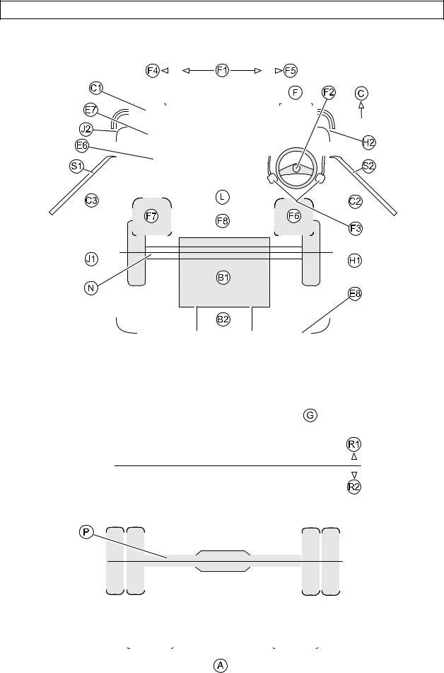
Marks |
Mounting position |
A
B1
B2
C
C1
C2
C3
E6
E7
E8
F
F1
F2
F3
F4
F5
F6
F7
F8
G
H1
H2
J1
J2
L
N
P
R1
R2
S1
S2
............................................................................................................. Tail
............................................................................................................. Engine
............................................................................................................. Gearbox
............................................................................................................. Front
............................................................................................................. Bumper
............................................................................................................. Entrance right
............................................................................................................. Entrance left
............................................................................................................. Central electrics area
............................................................................................................. Control unit racks
............................................................................................................. Rear wall of cab
............................................................................................................. Instrument panel
............................................................................................................. Central part
............................................................................................................. Steering wheel/column
............................................................................................................. Foot pedals
............................................................................................................. Front wall, inside left
............................................................................................................. Front wall, inside right
............................................................................................................. Driving seat
............................................................................................................. Passenger seat
............................................................................................................. Control panel
............................................................................................................. Battery box
............................................................................................................. B-pillar on driver's side
............................................................................................................. A-pillar on driver's side
............................................................................................................. B-pillar on passenger's side
............................................................................................................. A-pillar on passenger's side
............................................................................................................. Ceiling/roof
............................................................................................................. Front axle
............................................................................................................. Rear axle
............................................................................................................. Front parts of frame
............................................................................................................. Rear part of frame
............................................................................................................. Door left
............................................................................................................. Door right
K 90 |
1.60 - 3 |
GENERAL REMARKS
Mounting positions for right-hand drive
|
|
|
|
|
|
|
|
|
|
|
|
|
|
|
|
|
|
|
|
|
|
|
|
|
|
|
|
|
|
|
|
|
|
|
|
|
|
|
|
|
|
|
|
|
|
|
|
|
|
|
|
|
|
|
|
|
|
|
|
|
|
|
|
|
|
|
|
|
|
|
|
|
|
|
|
|
|
|
|
|
|
|
|
|
|
|
|
|
|
|
|
|
|
|
|
|
|
|
|
|
|
|
|
|
|
|
|
|
|
|
|
|
|
|
|
|
|
|
|
|
|
|
|
|
|
|
|
|
|
|
|
|
|
|
|
|
|
|
|
|
|
|
|
|
|
|
|
|
|
|
|
|
|
|
|
|
|
|
|
|
|
|
|
|
|
|
|
|
|
|
|
|
|
|
|
|
|
|
|
|
|
|
|
|
|
|
|
|
|
|
|
|
|
|
|
|
|
|
|
|
|
|
|
|
|
|
|
|
|
|
|
|
|
|
|
|
|
|
|
|
|
|
|
|
|
|
|
|
|
|
|
|
|
|
|
|
|
|
|
|
|
|
|
|
|
|
|
|
|
|
|
|
|
|
|
|
|
|
|
|
|
|
|
|
|
|
|
|
|
|
|
|
|
|
|
|
|
|
|
|
|
|
|
|
|
|
|
|
|
|
|
|
|
|
|
|
|
|
|
|
|
|
|
|
|
|
|
|
|
|
|
|
|
|
|
|
|
|
|
|
|
|
|
|
|
|
|
|
|
|
|
|
|
|
|
|
|
|
|
|
|
|
|
|
|
|
|
|
|
|
|
|
|
|
|
|
|
|
|
|
|
|
|
|
|
|
|
|
|
|
|
|
|
|
|
|
|
|
|
|
|
|
|
|
|
|
|
|
|
|
|
|
|
|
|
|
|
|
|
|
|
|
|
|
|
|
|
|
|
|
|
|
|
|
|
|
|
|
|
|
|
|
|
|
|
|
|
|
|
|
|
|
|
|
|
|
|
|
|
|
|
|
|
|
|
|
|
|
|
|
|
|
|
|
|
|
|
|
|
|
|
|
|
|
|
|
|
|
|
|
|
|
|
|
|
|
|
|
|
|
|
|
|
|
|
|
|
|
|
|
|
|
|
|
|
|
|
|
|
|
|
|
|
|
|
|
|
|
|
|
|
|
|
|
|
|
|
|
|
|
|
|
|
|
|
|
|
|
|
|
|
|
|
|
|
|
|
|
|
|
|
|
|
|
|
|
|
|
|
|
|
|
|
|
|
|
|
|
|
|
|
|
|
|
|
|
|
|
|
|
|
|
|
|
|
|
|
|
|
|
|
|
|
|
|
|
|
|
|
|
|
|
|
|
|
|
|
|
|
|
|
|
|
|
|
|
|
|
|
|
|
|
|
|
|
|
|
|
|
|
|
|
|
|
|
|
|
|
|
|
|
|
|
|
|
|
|
|
|
|
|
|
|
|
|
|
|
|
|
|
|
|
|
|
|
|
|
|
|
|
|
|
|
|
|
|
|
|
|
|
|
|
|
|
|
|
|
|
|
|
|
|
|
|
|
|
|
|
|
|
|
|
|
|
|
|
|
|
|
|
|
|
|
|
|
|
|
|
|
|
|
|
|
|
|
|
|
|
|
|
|
|
|
|
|
|
|
|
|
|
|
|
|
|
|
|
|
|
|
|
|
|
|
|
|
|
|
|
|
|
|
|
|
|
|
|
|
|
|
|
|
|
|
|
|
|
|
|
|
|
|
|
|
|
|
|
|
|
|
|
|
|
|
|
|
|
|
|
|
|
|
|
|
|
|
|
|
|
|
|
|
|
|
|
|
|
|
|
|
|
|
|
|
|
|
|
|
|
|
|
|
|
|
|
|
|
|
|
|
|
|
|
|
|
|
|
|
|
|
|
|
|
|
|
|
|
|
|
|
|
|
|
|
|
|
|
|
|
|
|
|
|
|
|
|
|
|
|
|
|
|
|
|
|
|
|
|
|
|
|
|
|
|
|
|
|
|
|
|
|
|
|
|
|
|
|
|
|
|
|
|
|
|
|
|
|
|
|
|
|
|
|
|
|
|
|
|
|
|
|
|
|
|
|
|
|
|
|
|
|
|
|
|
|
|
|
|
|
|
|
|
|
|
|
|
|
|
|
|
|
|
|
|
|
|
|
|
|
|
|
|
|
|
|
|
|
|
|
|
|
|
|
|
|
|
|
|
|
|
|
|
|
|
|
|
|
|
|
|
|
|
|
|
|
|
|
|
|
|
|
|
|
|
|
|
|
|
|
|
|
|
|
|
|
|
|
|
|
|
|
|
|
|
|
|
|
|
|
|
|
|
|
|
|
|
|
|
|
|
|
|
|
|
|
|
|
|
|
|
|
|
|
|
|
|
|
|
|
|
|
|
|
|
|
|
|
|
|
|
|
|
|
|
|
|
|
|
|
|
|
|
|
|
|
|
|
|
|
|
|
|
|
|
|
|
|
|
|
|
|
|
|
|
|
|
|
|
|
|
|
|
|
|
|
|
|
|
|
|
|
|
|
|
|
|
|
|
|
|
|
|
|
|
|
|
|
|
|
|
|
|
|
|
|
|
|
|
|
|
|
|
|
|
|
|
|
|
|
|
|
|
|
|
|
|
|
|
|
|
|
|
|
|
|
|
|
|
|
|
|
|
|
|
|
|
|
|
|
|
|
|
|
|
|
|
|
|
|
|
|
|
|
|
|
|
|
|
|
|
|
|
|
|
|
|
|
|
|
|
|
|
|
|
|
|
|
|
|
|
|
|
|
|
|
|
|
|
|
|
|
|
|
|
|
|
|
|
|
|
|
|
|
|
|
|
|
|
|
|
|
|
|
|
|
|
|
|
|
|
|
|
|
|
|
|
|
|
|
|
|
|
|
|
|
|
|
|
|
|
|
|
|
|
|
|
|
|
|
|
|
|
|
|
|
|
|
|
|
|
|
|
|
|
|
|
|
|
|
|
|
|
|
|
|
|
|
|
|
|
|
|
|
|
|
|
|
|
|
|
|
|
|
|
|
|
|
|
|
|
|
|
|
|
|
|
|
|
|
|
|
|
|
|
|
|
|
|
|
|
|
|
|
|
|
|
|
|
|
|
|
|
|
|
|
|
|
|
|
|
|
|
|
|
|
|
|
|
|
|
|
|
|
|
|
|
|
|
|
|
|
|
|
|
|
|
|
|
|
|
|
|
|
|
|
|
|
|
|
|
|
|
|
|
|
|
|
|
|
|
|
|
|
|
|
|
|
|
|
|
|
|
|
|
|
|
|
|
|
|
|
|
|
|
|
|
|
|
|
|
|
|
|
|
|
|
|
|
|
|
|
|
|
|
|
|
|
|
|
|
|
|
|
|
|
|
|
|
|
|
|
|
|
|
|
|
|
|
|
|
|
|
|
|
|
|
|
|
|
|
|
|
|
|
|
|
|
|
|
|
|
|
|
|
|
|
|
|
|
|
|
|
|
|
|
|
|
|
|
|
|
|
|
|
|
|
|
|
|
|
|
|
|
|
|
|
|
|
|
|
|
|
|
|
|
|
|
|
|
|
|
|
|
|
|
|
|
|
|
|
|
|
|
|
|
|
|
|
|
|
|
|
|
|
|
|
|
|
|
|
|
|
|
|
|
|
|
|
|
|
|
|
|
|
|
|
|
|
|
|
|
|
|
|
|
|
|
|
|
|
|
|
|
|
|
|
|
|
|
|
|
|
|
|
|
|
|
|
|
|
|
|
|
|
|
|
|
|
|
|
|
|
|
|
|
|
|
|
|
|
|
|
|
|
|
|
|
|
|
|
|
|
|
|
|
|
|
|
|
|
|
|
|
|
|
|
|
|
|
|
|
|
|
|
|
|
|
|
|
|
|
|
|
|
|
|
|
|
|
|
|
|
|
|
|
|
|
|
|
|
|
|
|
|
|
|
|
|
|
|
|
|
|
|
|
|
|
|
|
|
|
|
|
|
|
|
|
|
|
|
|
|
|
|
|
|
|
|
|
|
|
|
|
|
|
|
|
|
|
|
|
|
|
|
|
|
|
|
|
|
|
|
|
|
|
|
|
|
|
|
|
|
|
|
|
|
|
|
|
|
|
|
|
|
|
|
|
|
|
|
|
|
|
|
|
|
|
|
|
|
|
|
|
|
|
|
|
|
|
|
|
|
|
|
|
|
|
|
|
|
|
|
|
|
|
|
|
|
|
|
|
|
|
|
|
|
|
|
|
|
|
|
|
|
|
|
|
|
|
|
|
|
|
|
|
|
|
|
|
|
|
|
|
|
|
|
|
|
|
|
|
|
|
|
|
|
|
|
|
|
|
|
|
|
|
|
|
|
|
|
|
|
|
|
|
|
|
|
|
|
|
|
|
|
|
|
|
|
|
|
|
|
|
|
|
|
|
|
|
|
|
|
|
|
|
|
|
|
|
|
|
|
|
|
|
|
|
|
|
|
|
|
|
|
|
|
|
|
|
|
|
|
|
|
|
|
|
|
|
|
|
|
|
|
|
|
|
|
|
|
|
|
|
|
|
|
|
|
|
|
|
|
|
|
|
|
|
|
|
|
|
|
|
|
|
|
|
|
|
|
|
|
|
|
|
|
|
|
|
|
|
|
|
|
|
|
|
|
|
|
|
|
|
|
|
|
|
|
|
|
|
|
|
|
|
|
|
|
|
|
|
|
|
|
|
|
|
|
|
|
|
|
|
|
|
|
|
|
|
|
|
|
|
|
|
|
|
|
|
|
|
|
|
|
|
|
|
|
|
|
|
|
|
|
|
|
|
|
|
|
|
|
|
|
|
|
|
|
|
|
|
|
|
|
|
|
|
|
|
|
|
|
|
|
|
|
|
|
|
|
|
|
|
|
|
|
|
|
|
|
|
|
|
|
|
|
|
|
|
|
|
|
|
|
|
|
|
|
|
|
|
|
|
|
|
|
|
|
|
|
|
|
|
|
|
|
|
|
|
|
|
|
|
|
|
|
|
|
|
|
|
|
|
|
|
|
|
|
|
|
|
|
|
|
|
|
|
|
|
|
|
|
|
|
1.60 - 4 |
|
|
|
|
|
|
|
|
|
|
|
|
|
|
|
|
|
|
|
|
|
K 90 |
|
|
||||||||||||||||||||||||||

GENERAL REMARKS
Marks |
Mounting position |
A
B1
B2
C
C1
C2
C3
E6
E7
E8
F
F1
F2
F3
F4
F5
F6
F7
F8
G
H1
H2
J1
J2
L
N
P
R1
R2
S1
S2
............................................................................................................. Tail
............................................................................................................. Engine
............................................................................................................. Gearbox
............................................................................................................. Front
............................................................................................................. Bumper
............................................................................................................. Entrance right
............................................................................................................. Entrance left
............................................................................................................. Central electrics area
............................................................................................................. Control unit racks
............................................................................................................. Rear wall of cab
............................................................................................................. Instrument panel
............................................................................................................. Central part
............................................................................................................. Steering wheel/column
............................................................................................................. Foot pedals
............................................................................................................. Front wall, inside left
............................................................................................................. Front wall, inside right
............................................................................................................. Driving seat
............................................................................................................. Passenger seat
............................................................................................................. Control panel
............................................................................................................. Battery box
............................................................................................................. B-pillar on driver's side
............................................................................................................. A-pillar on driver's side
............................................................................................................. B-pillar on passenger's side
............................................................................................................. A-pillar on passenger's side
............................................................................................................. Ceiling/roof
............................................................................................................. Front axle
............................................................................................................. Rear axle
............................................................................................................. Front parts of frame
............................................................................................................. Rear part of frame
............................................................................................................. Door left
............................................................................................................. Door right
K 90 |
1.60 - 5 |

GENERAL REMARKS
Search criteria |
|
|
Ascending according to wiring diagram title |
|
|
Name |
Wiring |
|
|
diagram no. |
Page |
Additional headlight |
81.99192.2461 4.26 - 26 |
|
Air conditioning unit |
81.99192.1380 4.11 - 4 |
|
Airbag |
81.99192.2572 4.01 - 2 |
|
All-round marker light 1 on roof |
81.99192.1412 4.18 - 72 |
|
All-round marker light 2 on pedestal |
81.99192.1414 4.18 - 76 |
|
All-round marker light 2 on roof |
81.99192.1413 4.18 - 74 |
|
All-round marker light, left, on pedestal |
81.99192.1416 4.18 - 78 |
|
All-round marker light, right, on pedestal |
81.99192.1415 4.18 - 80 |
|
AS-TRONIC transmission (12-gear) |
81.99192.2993 4.07 - 2 |
|
AS-TRONIC transmission (16-gear) |
81.99192.2992 4.07 - 6 |
|
ASR traction control indicator light |
81.99192.1358 4.01 - 26 |
|
ASR traction control slip threshold control switch |
81.99192.1359 |
4.01 - 28 |
ASR traction control/electronic stability program |
81.99192.2862 |
4.01 - 30 |
ASR/ESP indicator light |
||
ASR traction control/electronic stability program |
81.99192.1360 4.01 - 32 |
|
ASR/ESP slip threshold control switch |
||
Bunk light, bottom (LL) |
81.99192.1397 4.19 - 18 |
|
Bunk light, bottom (RL) |
81.99192.1398 4.19 - 20 |
|
Bunk light, top |
81.99192.1396 4.19 - 16 |
|
Cab tilt device, electrical |
81.99192.1370 4.06 - 4 |
|
CAN databus driveline (T-CAN) |
81.99192.2359 4.03 - 4 |
|
CAN databus driveline (T-CAN) with AS-TRONIC |
81.99192.2522 4.03 - 6 |
|
CAN databus driveline (T-CAN) with AS-TRONIC/special customer module |
81.99192.2433 4.03 - 18 |
|
CAN databus driveline (T-CAN) with ECAS/AS-TRONIC/RAS-EC |
81.99192.2783 4.03 - 26 |
|
CAN databus driveline (T-CAN) with intarder or retarder |
81.99192.2521 |
4.03 - 10 |
CAN databus driveline (T-CAN) with intarder or retarder/ |
81.99192.2435 |
4.03 - 22 |
AS-TRONIC/special customer module |
||
CAN databus driveline (T-CAN) with intarder or retarder/ |
81.99192.2432 4.03 - 14 |
|
special customer module |
||
CAN databus driveline (T-CAN) with intarder or retarder/AS-TRONIC |
81.99192.2524 4.03 - 12 |
|
CAN databus driveline (T-CAN) with special customer module |
81.99192.2428 4.03 - 8 |
|
CAN databus driveline (T-CAN) without ECAM |
81.99192.2811 4.03 - 30 |
|
CAN databus driveline (T-CAN) without ECAM but with AS-TRONIC |
81.99192.2824 |
4.03 - 32 |
CAN databus driveline (T-CAN) without ECAM but with AS-TRONIC/ |
81.99192.2819 |
4.03 - 38 |
special customer module |
||
CAN databus driveline (T-CAN) without ECAM but with ECAS/ |
81.99192.2827 4.03 - 42 |
|
AS-TRONIC/RAS-EC |
||
CAN databus driveline (T-CAN) without ECAM but with intarder or retarder |
81.99192.2823 |
4.03 - 34 |
CAN databus driveline (T-CAN) without ECAM but with intarder or retarder/ |
81.99192.2818 |
4.03 - 46 |
special customer module |
||
CAN databus driveline (T-CAN) without ECAM but with intarder or retarder/ |
81.99192.2826 |
4.03 - 50 |
AS-TRONIC |
||
CAN databus driveline (T-CAN) without ECAM but with intarder or retarder/ |
81.99192.2821 |
4.03 - 52 |
AS-TRONIC/special customer module |
||
CAN databus driveline (T-CAN) without ECAM but with special |
81.99192.2814 4.03 - 36 |
|
customer module |
||
CAN databus instrumentation (I-CAN)/tachograph (FS-CAN) |
81.99192.2377 4.03 - 2 |
|
Cargo area lighting |
81.99192.1384 4.12 - 4 |
|
Central lubrication |
81.99192.1467 4.26 - 2 |
|
Cool box |
81.99192.1382 4.11 - 12 |
|
Cullmann phone with radio 24V and CD changer MAN-Sound (LL) |
81.99192.1447 4.20 - 10 |
|
Cullmann phone with radio 24V and CD changer MAN-Sound (RL) |
81.99192.2878 4.20 - 14 |
|
Cullmann phone with radio 24V MAN-Sound (LL) |
81.99192.2871 4.20 - 2 |
|
Cullmann phone with radio 24V MAN-Sound (RL) |
81.99192.2872 4.20 - 6 |
|
Differential lock longitudinal and transverse 3-axle |
81.99192.1366 4.04 - 2 |
|
Differential lock transverse, rear axle |
81.99192.1365 |
4.04 - 4 |
K 90 |
1.99 - 1 |

GENERAL REMARKS
Name |
Wiring |
|
|
|
diagram no. |
Page |
|
Door module (LL) |
81.99192.2989 4.20 - 34 |
||
Door module (RL) |
81.99192.2990 4.20 - 44 |
||
Driving dynamics control |
81.99192.2843 4.06 - 2 |
||
EATON RTSO transmission (LL) |
81.99192.2601 4.07 - 10 |
||
EATON RTSO transmission (RL) |
81.99192.2417 4.07 - 14 |
||
EBS electronic braking system |
81.99192.2987 4.05 - 2 |
||
ECAM electronically controlled compressed air device, fallback level |
81.99192.2810 4.05 - 8 |
||
ECAS electronically controlled air suspension 4x2 FL (semitrailer) |
81.99192.1336 4.05 - 14 |
||
ECAS electronically controlled air suspension 4x2 FL (truck) |
81.99192.1337 4.05 - 10 |
||
ECAS electronically controlled air suspension 4x2 FLL |
81.99192.1338 4.05 - 18 |
||
ECAS electronically controlled air suspension 6x2 FNL |
81.99192.1339 4.05 - 22 |
||
ECAS electronically controlled air suspension 6x2 FNL (Nordland) |
81.99192.1348 4.05 - 26 |
||
ECAS electronically controlled air suspension 6x2 FNLL |
81.99192.1340 4.05 - 30 |
||
ECAS electronically controlled air suspension 6x2 FNLL (Nordland) |
81.99192.1349 4.05 - 34 |
||
ECAS electronically controlled air suspension 6x2 FVL |
81.99192.1341 4.05 - 38 |
||
ECAS electronically controlled air suspension, switch level 1/2 |
81.99192.1368 |
4.05 |
- 42 |
ECAS electronically controlled air suspension/EFR electronic |
81.99192.1342 |
|
- 44 |
shock absorber control 4x2 FL (semitrailer) |
4.05 |
||
ECAS electronically controlled air suspension/EFR electronic |
81.99192.1345 |
|
- 56 |
shock absorber control 6x2 FNL |
4.05 |
||
ECAS electronically controlled air suspension/EFR electronic |
81.99192.1350 |
|
- 60 |
shock absorber control 6x2 FNL (Nordland) |
4.05 |
||
ECAS electronically controlled air suspension/EFR electronic |
81.99192.1346 |
|
- 64 |
shock absorber control 6x2 FVL |
4.05 |
||
ECAS electronically controlled air suspension/EFR electronic |
81.99192.1347 |
|
- 68 |
shock absorber control 6x2 FNLL |
4.05 |
||
ECAS electronically controlled air suspension/EFR electronic |
81.99192.1351 |
|
- 72 |
shock absorber control 6x2 FNLL (Nordland) |
4.05 |
||
ECAS electronically controlled air suspension/EFR electronic |
81.99192.1343 |
|
- 48 |
shock absorber control 4x2 FL (truck) |
4.05 |
||
ECAS electronically controlled air suspension/EFR electronic |
81.99192.1344 4.05 - 52 |
||
shock absorber control 6x2 FNL |
|||
EDC electronically controlled diesel injection EDC MS6.1 (EURO 2) |
81.99192.2985 |
4.05 |
- 76 |
EDC electronically controlled diesel injection EDC MS6.1 with |
81.99192.2986 4.05 - 82 |
||
exhaust gas recirculation (EURO 3) |
|||
EDC electronically controlled diesel injection EDC7 Common Rail D0836LF |
81.99192.2692 4.05 - 88 |
||
Emergency battery shutdown |
81.99192.1362 4.02 - 2 |
||
Engine brake, automatic |
81.99192.1385 4.13 - 2 |
||
EVB electronically controlled engine brake, controlled |
81.99192.2832 4.05 - 96 |
||
Fuel filter heater |
81.99192.2487 4.11 - 8 |
||
Fuel filter heater, Separ |
81.99192.2665 4.11 - 10 |
||
Headlight cleaning unit (LL) |
81.99192.1392 4.19 - 8 |
||
Headlight cleaning unit (RL) |
81.99192.1393 4.19 - 10 |
||
Headlight gas discharge with headlight levelling (LL) |
81.99192.2651 4.19 - 2 |
||
Headlight gas discharge with headlight levelling (RL) |
81.99192.2653 4.19 - 4 |
||
Headlight gas discharge without headlight levelling |
81.99192.2652 4.19 - 6 |
||
Headlight levelling (LL) |
81.99192.2477 4.12 - 6 |
||
Headlight levelling (RL) |
81.99192.2445 4.12 - 8 |
||
Heating for hydraulic gearshift (HGS) (LL) |
81.99192.2684 4.08 - 4 |
||
Heating for hydraulic gearshift (HGS) (RL) |
81.99192.2690 4.08 - 6 |
||
Horn switchover (LL) |
81.99192.1375 4.08 - 8 |
||
Horn switchover (RL) |
81.99192.1376 4.08 - 10 |
||
Intarder ZF-EST 48 |
81.99192.1378 4.09 - 4 |
||
Interior lighting, roof (white/red) |
81.99192.1377 4.09 - 2 |
||
Locker lighting, rear left (LL) |
81.99192.2489 4.19 - 42 |
||
Locker lighting, rear left (RL) |
81.99192.2411 4.19 - 44 |
||
Locker lighting, rear right (LL) |
81.99192.2490 4.19 - 46 |
||
Locker lighting, rear right (RL) |
81.99192.2412 4.19 - 48 |
||
Locker lighting, top (left, middle) (LL) |
81.99192.1404 4.19 - 50 |
||
Locker lighting, top (left, middle) (RL) |
81.99192.1405 |
4.19 - 52 |
|
1.99 - 2 |
K 90 |
GENERAL REMARKS
Name |
Wiring |
|
|
|
diagram no. |
Page |
|
Locker lighting, top (left, middle, right) (LL) |
81.99192.1406 4.19 - 54 |
||
Locker lighting, top (left, middle, right) (RL) |
81.99192.1407 4.19 - 56 |
||
Main battery switch (electric) |
81.99192.1361 4.02 - 6 |
||
Main battery switch (mechanical) |
81.99192.2495 4.02 - 8 |
||
Nokia phone with radio 24V and CD changer MAN-Sound (LL) |
81.99192.2875 |
4.20 |
- 26 |
Nokia phone with radio 24V and CD changer MAN-Sound (RL) |
81.99192.2876 4.20 - 30 |
||
Nokia phone with radio 24V MAN-Sound (LL) |
81.99192.2873 4.20 - 18 |
||
Nokia phone with radio 24V MAN-Sound (RL) |
81.99192.2874 4.20 - 22 |
||
Power take-off 1 |
81.99192.1388 4.14 - 2 |
||
Power take-off 2 |
81.99192.1389 4.14 - 4 |
||
Preparation cooling superstructure (tractor vehicle) |
81.99192.1469 4.22 - 2 |
||
Preparation cooling superstructure (tractor vehicle, trailer) |
81.99192.1468 4.22 - 6 |
||
Preparation LSVA (performance-related heavy traffic levy) |
81.99192.1464 4.22 - 12 |
||
Preparation trailing axle control, semitrailer |
81.99192.1465 4.22 - 14 |
||
Preparation, central lubrication |
81.99192.1466 4.22 - 16 |
||
Radio 12V |
81.99192.2475 4.18 - 2 |
||
Radio 12V MAN-Sound (LL) |
81.99192.2484 4.18 - 4 |
||
Radio 12V MAN-Sound (RL) |
81.99192.2444 4.18 - 6 |
||
Radio 24V |
81.99192.2879 4.18 - 8 |
||
Radio 24V MAN-Sound (LL) |
81.99192.2855 4.18 - 10 |
||
Radio 24V MAN-Sound (RL) |
81.99192.2856 4.18 - 12 |
||
Radio 24V with CD changer and MAN-Sound (LL) |
81.99192.2858 4.18 - 14 |
||
Radio 24V with CD changer and MAN-Sound (RL) |
81.99192.2859 4.18 - 18 |
||
Radio navigation system 12V (LL) |
81.99192.1432 4.18 - 24 |
||
Radio navigation system 12V (RL) |
81.99192.1433 4.18 - 26 |
||
Radio navigation system 12V with CD changer (LL) |
81.99192.1434 4.18 - 28 |
||
Radio navigation system 12V with CD changer (RL) |
81.99192.1435 4.18 - 30 |
||
Radio navigation system 12V with Cullmann phone (LL) |
81.99192.1436 4.18 - 32 |
||
Radio navigation system 12V with Cullmann phone (RL) |
81.99192.1437 4.18 - 36 |
||
Radio navigation system 12V with Cullmann phone and CD changer (LL) |
81.99192.1440 4.18 - 48 |
||
Radio navigation system 12V with Cullmann phone and CD changer (RL) |
81.99192.1441 4.18 - 52 |
||
Radio navigation system 12V with Nokia phone (LL) |
81.99192.1438 4.18 - 40 |
||
Radio navigation system 12V with Nokia phone (RL) |
81.99192.1439 4.18 - 44 |
||
Radio navigation system 12V with Nokia phone and CD changer (LL) |
81.99192.1442 4.18 - 56 |
||
Radio navigation system 12V with Nokia phone and CD changer (RL) |
81.99192.1443 4.18 - 60 |
||
Radio remote control (infrared) |
81.99192.1371 4.18 - 22 |
||
Retarder VOITH DIGIPROP (CAN) |
81.99192.1410 4.18 - 66 |
||
Retarder, hydroretarder (CAN) |
81.99192.1411 4.18 - 68 |
||
Retarder/intarder, automatic |
81.99192.1372 4.18 - 64 |
||
Reversing stop |
81.99192.1409 4.18 - 70 |
||
Seat adjustment, electric (driver) |
81.99192.1483 4.19 - 28 |
||
Seat adjustment, electric (passenger) |
81.99192.1484 4.19 - 30 |
||
Seat belt indicator, driver |
81.99192.1374 4.07 - 26 |
||
Seat heating, driver |
81.99192.2494 4.19 - 24 |
||
Seat heating, driver and passenger |
81.99192.2493 4.19 - 26 |
||
Side marker lights (LL) |
81.99192.2592 4.19 - 22 |
||
Socket 12V |
81.99192.2569 4.19 - 58 |
||
Socket 24V |
81.99192.2570 4.19 - 60 |
||
Socket 24V in wiring trough |
81.99192.2796 4.19 - 62 |
||
Socket, tanker |
81.99192.2655 4.19 - 64 |
||
Special customised module |
81.99192.1381 4.11 - 14 |
||
START-STOP device at end of frame |
81.99192.1402 4.19 - 38 |
||
START-STOP device on engine |
81.99192.1401 4.19 - 36 |
||
START-STOP device on engine and end of frame |
81.99192.1403 4.19 - 40 |
||
Sunblind, electric |
81.99192.1399 4.19 - 32 |
||
Sunroof (INALFA) (LL) |
81.99192.1394 4.19 - 12 |
||
Sunroof (INALFA) (RL) |
81.99192.1395 4.19 - 14 |
||
Supplementary heating D1LCC/D3LCC with TRS |
81.99192.1472 4.26 - 4 |
||
Supplementary heating D1LCC/D3LCC without TRS |
81.99192.1471 |
4.26 - 6 |
|
K 90 |
1.99 - 3 |

GENERAL REMARKS
Name |
Wiring |
|
|
|
diagram no. |
Page |
|
Supplementary heating D5W with TRS |
81.99192.1478 4.26 - 8 |
||
Supplementary heating D5W without TRS |
81.99192.1477 4.26 - 10 |
||
Supplementary heating Thermo 50 with TRS |
81.99192.1476 4.26 - 12 |
||
Supplementary heating Thermo 50 without TRS |
81.99192.1475 4.26 - 14 |
||
Supplementary heating Truma E24-2 with TRS |
81.99192.1480 |
4.26 |
- 18 |
Supplementary heating Truma E24-2 without TRS |
81.99192.1479 4.26 - 20 |
||
Supplementary heating Webasto Airtop 2000 OEM and 3500 with TRS |
81.99192.1473 |
4.26 |
- 22 |
Supplementary heating Webasto Airtop 2000 OEM and 3500 without TRS |
81.99192.1474 4.26 - 24 |
||
Supplementary heating, TRS shutdown |
81.99192.2621 4.26 - 16 |
||
Tailgate |
81.99192.1537 4.12 - 2 |
||
Tipper indicator |
81.99192.1379 4.11 - 2 |
||
Trailer charge 24V |
81.99192.2616 4.08 - 2 |
||
Trailer lighting socket 24V 15-pin |
81.99192.2499 4.01 - 10 |
||
Trailer lighting socket 24V 15-pin + 12V 13-pin |
81.99192.2650 4.01 - 22 |
||
Trailer lighting socket 24V 7-pin |
81.99192.2496 4.01 - 4 |
||
Trailer lighting socket 24V 7-pin + 12V 13-pin |
81.99192.2447 4.01 - 12 |
||
Trailer lighting socket 24V 7-pin/4-pin |
81.99192.2497 4.01 - 6 |
||
Trailer lighting socket 24V 7-pin/4-pin + 12V 13-pin |
81.99192.2448 4.01 - 14 |
||
Trailer lighting socket 24V 7-pin/7-pin |
81.99192.2498 4.01 - 8 |
||
Trailer lighting socket 24V 7-pin/7-pin + 12V 13-pin |
81.99192.2449 4.01 - 18 |
||
Vehicle immobiliser |
81.99192.2476 4.23 - 2 |
||
Voltage limiter |
81.99192.2850 4.19 - 34 |
||
Windscreen heating |
81.99192.2571 4.06 - 6 |
||
Windscreen heating (wide cab) |
81.99192.1373 4.06 - 8 |
||
Work spotlight on top of cab |
81.99192.1356 4.01 - 34 |
||
Work spotlight, cab closure (left/right) |
81.99192.1355 4.01 - 36 |
||
Work spotlight, cab closure (right) |
81.99192.1357 4.01 - 38 |
||
ZF transmission 16S151/16S181 (LL) |
81.99192.2579 4.07 - 18 |
||
ZF transmission 16S151/16S181 (RL) |
81.99192.2835 |
4.07 - 22 |
|
1.99 - 4 |
K 90 |

GENERAL REMARKS
Ascending according to wiring diagram title – part numbers |
|
|
|
Name |
Wiring |
|
|
|
diagram no. |
Page |
|
ECAS electronically controlled air suspension 4x2 FL (semitrailer) |
81.99192.1336 |
4.05 |
- 14 |
ECAS electronically controlled air suspension 4x2 FL (truck) |
81.99192.1337 |
4.05 |
- 10 |
ECAS electronically controlled air suspension 4x2 FLL |
81.99192.1338 |
4.05 |
- 18 |
ECAS electronically controlled air suspension 6x2 FNL |
81.99192.1339 |
4.05 |
- 22 |
ECAS electronically controlled air suspension 6x2 FNLL |
81.99192.1340 |
4.05 |
- 30 |
ECAS electronically controlled air suspension 6x2 FVL |
81.99192.1341 |
4.05 |
- 38 |
ECAS electronically controlled air suspension/EFR electronic |
81.99192.1342 |
|
- 44 |
shock absorber control 4x2 FL (semitrailer) |
4.05 |
||
ECAS electronically controlled air suspension/EFR electronic |
81.99192.1343 |
|
- 48 |
shock absorber control 4x2 FL (truck) |
4.05 |
||
ECAS electronically controlled air suspension/EFR electronic |
81.99192.1344 |
|
- 52 |
shock absorber control 6x2 FNL |
4.05 |
||
ECAS electronically controlled air suspension/EFR electronic |
81.99192.1345 |
|
- 56 |
shock absorber control 6x2 FNL |
4.05 |
||
ECAS electronically controlled air suspension/EFR electronic |
81.99192.1346 |
|
- 64 |
shock absorber control 6x2 FVL |
4.05 |
||
ECAS electronically controlled air suspension/EFR electronic |
81.99192.1347 |
|
- 68 |
shock absorber control 6x2 FNLL |
4.05 |
||
ECAS electronically controlled air suspension 6x2 FNL (Nordland) |
81.99192.1348 |
4.05 |
- 26 |
ECAS electronically controlled air suspension 6x2 FNLL (Nordland) |
81.99192.1349 |
4.05 |
- 34 |
ECAS electronically controlled air suspension/EFR electronic |
81.99192.1350 |
|
- 60 |
shock absorber control 6x2 FNL (Nordland) |
4.05 |
||
ECAS electronically controlled air suspension/EFR electronic |
81.99192.1351 |
|
- 72 |
shock absorber control 6x2 FNLL (Nordland) |
4.05 |
||
Work spotlight, cab closure (left/right) |
81.99192.1355 |
4.01 |
- 36 |
Work spotlight on top of cab |
81.99192.1356 |
4.01 |
- 34 |
Work spotlight, cab closure (right) |
81.99192.1357 |
4.01 |
- 38 |
ASR traction control indicator light |
81.99192.1358 |
4.01 |
- 26 |
ASR traction control slip threshold control switch |
81.99192.1359 |
4.01 |
- 28 |
ASR traction control/electronic stability program |
81.99192.1360 |
|
- 32 |
ASR/ESP slip threshold control switch |
4.01 |
||
Main battery switch (electric) |
81.99192.1361 |
4.02 |
- 6 |
Emergency battery shutdown |
81.99192.1362 |
4.02 |
- 2 |
Differential lock transverse, rear axle |
81.99192.1365 |
4.04 |
- 4 |
Differential lock longitudinal and transverse 3-axle |
81.99192.1366 |
4.04 |
- 2 |
ECAS electronically controlled air suspension, switch level 1/2 |
81.99192.1368 |
4.05 |
- 42 |
Cab tilt device, electrical |
81.99192.1370 |
4.06 |
- 4 |
Radio remote control (infrared) |
81.99192.1371 |
4.18 |
- 22 |
Retarder/intarder, automatic |
81.99192.1372 |
4.18 |
- 64 |
Windscreen heating (wide cab) |
81.99192.1373 |
4.06 |
- 8 |
Seat belt indicator, driver |
81.99192.1374 |
4.07 |
- 26 |
Horn switchover (LL) |
81.99192.1375 |
4.08 |
- 8 |
Horn switchover (RL) |
81.99192.1376 |
4.08 |
- 10 |
Interior lighting, roof (white/red) |
81.99192.1377 |
4.09 |
- 2 |
Intarder ZF-EST 48 |
81.99192.1378 |
4.09 |
- 4 |
Tipper indicator |
81.99192.1379 |
4.11 |
- 2 |
Air conditioning unit |
81.99192.1380 |
4.11 |
- 4 |
Special customised module |
81.99192.1381 |
4.11 |
- 14 |
Cool box |
81.99192.1382 |
4.11 |
- 12 |
Cargo area lighting |
81.99192.1384 |
4.12 |
- 4 |
Engine brake, automatic |
81.99192.1385 |
4.13 |
- 2 |
Power take-off 1 |
81.99192.1388 |
4.14 |
- 2 |
Power take-off 2 |
81.99192.1389 |
4.14 |
- 4 |
Headlight cleaning unit (LL) |
81.99192.1392 |
4.19 |
- 8 |
Headlight cleaning unit (RL) |
81.99192.1393 |
4.19 |
- 10 |
Sunroof (INALFA) (LL) |
81.99192.1394 |
4.19 |
- 12 |
K 90 |
1.99 - 5 |

GENERAL REMARKS
Name
Sunroof (INALFA) (RL) Bunk light, top
Bunk light, bottom (LL) Bunk light, bottom (RL) Sunblind, electric
START-STOP device on engine START-STOP device at end of frame
START-STOP device on engine and end of frame Locker lighting, top (left, middle) (LL)
Locker lighting, top (left, middle) (RL) Locker lighting, top (left, middle, right) (LL) Locker lighting, top (left, middle, right) (RL) Reversing stop
Retarder VOITH DIGIPROP (CAN) Retarder, hydroretarder (CAN) All-round marker light 1 on roof All-round marker light 2 on roof All-round marker light 2 on pedestal All-round marker light, right, on pedestal All-round marker light, left, on pedestal Radio navigation system 12V (LL) Radio navigation system 12V (RL)
Radio navigation system 12V with CD changer (LL) Radio navigation system 12V with CD changer (RL) Radio navigation system 12V with Cullmann phone (LL) Radio navigation system 12V with Cullmann phone (RL) Radio navigation system 12V with Nokia phone (LL) Radio navigation system 12V with Nokia phone (RL)
Radio navigation system 12V with Cullmann phone and CD changer (LL) Radio navigation system 12V with Cullmann phone and CD changer (RL) Radio navigation system 12V with Nokia phone and CD changer (LL)
Radio navigation system 12V with Nokia phone and CD changer (RL) Cullmann phone with radio 24V and CD changer MAN-Sound (LL) Preparation LSVA (performance-related heavy traffic levy) Preparation trailing axle control, semitrailer
Preparation, central lubrication Central lubrication
Preparation cooling superstructure (tractor vehicle, trailer) Preparation cooling superstructure (tractor vehicle) Supplementary heating D1LCC/D3LCC without TRS Supplementary heating D1LCC/D3LCC with TRS
Supplementary heating Webasto Airtop 2000 OEM and 3500 with TRS Supplementary heating Webasto Airtop 2000 OEM and 3500 without TRS Supplementary heating Thermo 50 without TRS
Supplementary heating Thermo 50 with TRS Supplementary heating D5W without TRS Supplementary heating D5W with TRS Supplementary heating Truma E24-2 without TRS Supplementary heating Truma E24-2 with TRS Seat adjustment, electric (driver)
Seat adjustment, electric (passenger) Tailgate
CAN databus driveline (T-CAN)
CAN databus instrumentation (I-CAN)/tachograph (FS-CAN) Locker lighting, rear left (RL)
Locker lighting, rear right (RL) EATON RTSO transmission (RL)
CAN databus driveline (T-CAN) with special customer module CAN databus driveline (T-CAN) with intarder or retarder/special
customer module
1.99 - 6 |
K 90 |
Wiring
diagram no. Page
81.99192.1395 4.19 - 14 81.99192.1396 4.19 - 16 81.99192.1397 4.19 - 18 81.99192.1398 4.19 - 20 81.99192.1399 4.19 - 32 81.99192.1401 4.19 - 36 81.99192.1402 4.19 - 38 81.99192.1403 4.19 - 40 81.99192.1404 4.19 - 50 81.99192.1405 4.19 - 52 81.99192.1406 4.19 - 54 81.99192.1407 4.19 - 56 81.99192.1409 4.18 - 70 81.99192.1410 4.18 - 66 81.99192.1411 4.18 - 68 81.99192.1412 4.18 - 72 81.99192.1413 4.18 - 74 81.99192.1414 4.18 - 76 81.99192.1415 4.18 - 80 81.99192.1416 4.18 - 78 81.99192.1432 4.18 - 24 81.99192.1433 4.18 - 26 81.99192.1434 4.18 - 28 81.99192.1435 4.18 - 30 81.99192.1436 4.18 - 32 81.99192.1437 4.18 - 36 81.99192.1438 4.18 - 40 81.99192.1439 4.18 - 44 81.99192.1440 4.18 - 48 81.99192.1441 4.18 - 52 81.99192.1442 4.18 - 56 81.99192.1443 4.18 - 60 81.99192.1447 4.20 - 10 81.99192.1464 4.22 - 12 81.99192.1465 4.22 - 14 81.99192.1466 4.22 - 16 81.99192.1467 4.26 - 2 81.99192.1468 4.22 - 6 81.99192.1469 4.22 - 2 81.99192.1471 4.26 - 6 81.99192.1472 4.26 - 4 81.99192.1473 4.26 - 22 81.99192.1474 4.26 - 24 81.99192.1475 4.26 - 14 81.99192.1476 4.26 - 12 81.99192.1477 4.26 - 10 81.99192.1478 4.26 - 8 81.99192.1479 4.26 - 20 81.99192.1480 4.26 - 18 81.99192.1483 4.19 - 28 81.99192.1484 4.19 - 30 81.99192.1537 4.12 - 2 81.99192.2359 4.03 - 4 81.99192.2377 4.03 - 2 81.99192.2411 4.19 - 44 81.99192.2412 4.19 - 48 81.99192.2417 4.07 - 14 81.99192.2428 4.03 - 8
81.99192.2432 4.03 - 14

GENERAL REMARKS
Name |
Wiring |
|
|
|
diagram no. |
Page |
|
CAN databus driveline (T-CAN) with AS-TRONIC/special customer module |
81.99192.2433 |
4.03 |
- 18 |
CAN databus driveline (T-CAN) with intarder or retarder/AS-TRONIC/ |
81.99192.2435 |
|
- 22 |
special customer module |
4.03 |
||
Radio 12V MAN-Sound (RL) |
81.99192.2444 |
4.18 |
- 6 |
Headlight levelling (RL) |
81.99192.2445 |
4.12 |
- 8 |
Trailer lighting socket 24V 7-pin + 12V 13-pin |
81.99192.2447 |
4.01 |
- 12 |
Trailer lighting socket 24V 7-pin/4-pin + 12V 13-pin |
81.99192.2448 |
4.01 |
- 14 |
Trailer lighting socket 24V 7-pin/7-pin + 12V 13-pin |
81.99192.2449 |
4.01 |
- 18 |
Additional headlight |
81.99192.2461 |
4.26 |
- 26 |
Radio 12V |
81.99192.2475 |
4.18 |
- 2 |
Vehicle immobiliser |
81.99192.2476 |
4.23 |
- 2 |
Headlight levelling (LL) |
81.99192.2477 |
4.12 |
- 6 |
Radio 12V MAN-Sound (LL) |
81.99192.2484 |
4.18 |
- 4 |
Fuel filter heater |
81.99192.2487 |
4.11 |
- 8 |
Locker lighting, rear left (LL) |
81.99192.2489 |
4.19 |
- 42 |
Locker lighting, rear right (LL) |
81.99192.2490 |
4.19 |
- 46 |
Seat heating, driver and passenger |
81.99192.2493 |
4.19 |
- 26 |
Seat heating, driver |
81.99192.2494 |
4.19 |
- 24 |
Main battery switch (mechanical) |
81.99192.2495 |
4.02 |
- 8 |
Trailer lighting socket 24V 7-pin |
81.99192.2496 |
4.01 |
- 4 |
Trailer lighting socket 24V 7-pin/4-pin |
81.99192.2497 |
4.01 |
- 6 |
Trailer lighting socket 24V 7-pin/7-pin |
81.99192.2498 |
4.01 |
- 8 |
Trailer lighting socket 24V 15-pin |
81.99192.2499 |
4.01 |
- 10 |
CAN databus driveline (T-CAN) with intarder or retarder |
81.99192.2521 |
4.03 |
- 10 |
CAN databus driveline (T-CAN) with AS-TRONIC |
81.99192.2522 |
4.03 |
- 6 |
CAN databus driveline (T-CAN) with intarder or retarder/AS-TRONIC |
81.99192.2524 |
4.03 |
- 12 |
Socket 12V |
81.99192.2569 |
4.19 |
- 58 |
Socket 24V |
81.99192.2570 |
4.19 |
- 60 |
Windscreen heating |
81.99192.2571 |
4.06 |
- 6 |
Airbag |
81.99192.2572 |
4.01 |
- 2 |
ZF transmission 16S151/16S181 (LL) |
81.99192.2579 |
4.07 |
- 18 |
Side marker lights (LL) |
81.99192.2592 |
4.19 |
- 22 |
EATON RTSO transmission (LL) |
81.99192.2601 |
4.07 |
- 10 |
Trailer charge 24V |
81.99192.2616 |
4.08 |
- 2 |
Supplementary heating, TRS shutdown |
81.99192.2621 |
4.26 |
- 16 |
Trailer lighting socket 24V 15-pin + 12V 13-pin |
81.99192.2650 |
4.01 |
- 22 |
Headlight gas discharge with headlight levelling (LL) |
81.99192.2651 |
4.19 |
- 2 |
Headlight gas discharge without headlight levelling |
81.99192.2652 |
4.19 |
- 6 |
Headlight gas discharge with headlight levelling (RL) |
81.99192.2653 |
4.19 |
- 4 |
Socket, tanker |
81.99192.2655 |
4.19 |
- 64 |
Fuel filter heater, Separ |
81.99192.2665 |
4.11 |
- 10 |
Heating for hydraulic gearshift (HGS) (LL) |
81.99192.2684 |
4.08 |
- 4 |
Heating for hydraulic gearshift (HGS) (RL) |
81.99192.2690 |
4.08 |
- 6 |
EDC electronically controlled diesel injection EDC7 Common Rail D0836LF |
81.99192.2692 |
4.05 |
- 88 |
CAN databus driveline (T-CAN) with ECAS/AS-TRONIC/RAS-EC |
81.99192.2783 |
4.03 |
- 26 |
Socket 24V in wiring trough |
81.99192.2796 |
4.19 |
- 62 |
ECAM electronically controlled compressed air device, fallback level |
81.99192.2810 |
4.05 |
- 8 |
CAN databus driveline (T-CAN) without ECAM |
81.99192.2811 |
4.03 |
- 30 |
CAN databus driveline (T-CAN) without ECAM but with special |
81.99192.2814 |
|
- 36 |
customer module |
4.03 |
||
CAN databus driveline (T-CAN) without ECAM but with intarder or retarder/ |
81.99192.2818 |
|
- 46 |
special customer module |
4.03 |
||
CAN databus driveline (T-CAN) without ECAM but with AS-TRONIC/ |
81.99192.2819 |
|
- 38 |
special customer module |
4.03 |
||
CAN databus driveline (T-CAN) without ECAM but with intarder or retarder/ |
81.99192.2821 |
|
- 52 |
AS-TRONIC/special customer module |
4.03 |
||
CAN databus driveline (T-CAN) without ECAM but with intarder or retarder |
81.99192.2823 |
4.03 |
- 34 |
CAN databus driveline (T-CAN) without ECAM but with AS-TRONIC |
81.99192.2824 |
4.03 |
- 32 |
CAN databus driveline (T-CAN) without ECAM but with intarder or retarder/ |
81.99192.2826 |
|
- 50 |
AS-TRONIC |
4.03 |
||
K 90 |
1.99 - 7 |

GENERAL REMARKS
Name |
Wiring |
|
|
|
diagram no. |
Page |
|
CAN databus driveline (T-CAN) without ECAM but with ECAS/ |
81.99192.2827 |
|
- 42 |
AS-TRONIC/RAS-EC |
4.03 |
||
EVB electronically controlled engine brake, controlled |
81.99192.2832 |
4.05 |
- 96 |
ZF transmission 16S151/16S181 (RL) |
81.99192.2835 |
4.07 |
- 22 |
Driving dynamics control |
81.99192.2843 |
4.06 |
- 2 |
Voltage limiter |
81.99192.2850 |
4.19 |
- 34 |
Radio 24V MAN-Sound (LL) |
81.99192.2855 |
4.18 |
- 10 |
Radio 24V MAN-Sound (RL) |
81.99192.2856 |
4.18 |
- 12 |
Radio 24V with CD changer and MAN-Sound (LL) |
81.99192.2858 |
4.18 |
- 14 |
Radio 24V with CD changer and MAN-Sound (RL) |
81.99192.2859 |
4.18 |
- 18 |
ASR traction control/electronic stability program |
81.99192.2862 |
|
- 30 |
ASR/ESP indicator light |
4.01 |
||
Cullmann phone with radio 24V MAN-Sound (LL) |
81.99192.2871 |
4.20 |
- 2 |
Cullmann phone with radio 24V MAN-Sound (RL) |
81.99192.2872 |
4.20 |
- 6 |
Nokia phone with radio 24V MAN-Sound (LL) |
81.99192.2873 |
4.20 |
- 18 |
Nokia phone with radio 24V MAN-Sound (RL) |
81.99192.2874 |
4.20 |
- 22 |
Nokia phone with radio 24V and CD changer MAN-Sound (LL) |
81.99192.2875 |
4.20 |
- 26 |
Nokia phone with radio 24V and CD changer MAN-Sound (RL) |
81.99192.2876 |
4.20 |
- 30 |
Cullmann phone with radio 24V and CD changer MAN-Sound (RL) |
81.99192.2878 |
4.20 |
- 14 |
Radio 24V |
81.99192.2879 |
4.18 |
- 8 |
EDC electronically controlled diesel injection EDC MS6.1 (EURO 2) |
81.99192.2985 |
4.05 |
- 76 |
EDC electronically controlled diesel injection EDC MS6.1 with |
81.99192.2986 |
|
- 82 |
exhaust gas recirculation (EURO 3) |
4.05 |
||
EBS electronic braking system |
81.99192.2987 |
4.05 |
- 2 |
Door module (LL) |
81.99192.2989 |
4.20 |
- 34 |
Door module (RL) |
81.99192.2990 |
4.20 |
- 44 |
AS-TRONIC transmission (16-gear) |
81.99192.2992 |
4.07 |
- 6 |
AS-TRONIC transmission (12-gear) |
81.99192.2993 |
4.07 |
- 2 |
1.99 - 8 |
K 90 |

LL SERIES WIRING DIAGRAMS
K 90 |
3.01 - 1 |

LL SERIES WIRING DIAGRAMS
Contents
Names of circuits |
Wiring diagram no. |
Chapter/Page |
|
|
|
|
|
Series wiring diagrams (LL) |
81.99192.2981 |
3.01 |
|
Power supply, starting system |
Sheet 1 |
3.01 |
- 2 |
Power supply central vehicle computer, power supply intarder, EBS, ECAS, power supply retarder, |
Sheet 2 |
3.01 |
- 4 |
power supply vehicle management computer |
|
|
|
Earth distributor |
Sheet 3 |
3.01 |
- 6 |
Flame starting device, fan clutch, coolant temperature EDC, coolant level, |
Sheet 4 |
3.01 |
- 8 |
reserve lines engine START-STOP |
|
|
|
Steering hydraulic fluid level, diagnosis, pressure pickup air filter |
Sheet 5 |
3.01 |
- 10 |
Clutch fluid level sensor, heating thermostat, ZDR interface (vehicle management computer) |
Sheet 6 |
3.01 |
- 12 |
(MDB, HGB) |
|
|
|
Cruise control, vehicle speed control/vehicle speed limiting, additional retarding brake, |
Sheet 7 |
3.01 |
- 14 |
distributor line 60028 |
|
|
|
ECAM, indicator light for cab locking, tank level indicator |
Sheet 8 |
3.01 |
- 16 |
Horn, oil level sensor, engine brake, retarding brake pushbutton switch, external temperature |
Sheet 9 |
3.01 |
- 18 |
Wiper and washer system, heater fan |
Sheet 10 |
3.01 |
- 20 |
Cigarette lighter, ash tray illumination, gear lever, diagnosis vehicle management computer, |
Sheet 11 |
3.01 |
- 22 |
accelerator pedal unit |
|
|
|
Power supply +15V, instrumentation/tachograph |
Sheet 12 |
3.01 |
- 24 |
Lighting learning session, light switches |
Sheet 13 |
3.01 |
- 26 |
Parking lights left, parking lights right |
Sheet 14 |
3.01 |
- 28 |
Headlamp flasher, dipped beam, main beam, headlight levelling |
Sheet 15 |
3.01 |
- 30 |
Rear fog lights, front fog light/rear fog light circuitry, front fog light/supplementary fog lights |
Sheet 16 |
3.01 |
- 32 |
Brake light, parking brake, reversing light |
Sheet 17 |
3.01 |
- 34 |
Search lighting, power supply permanent consumers, entrance illumination/internal lighting |
Sheet 18 |
3.01 |
- 36 |
Light flashing unit |
Sheet 19 |
3.01 |
- 38 |
Reserve lines, reserve lines for trailer lighting socket, periphery of retarder |
Sheet 20 |
3.01 |
- 40 |
Intarder, retarder, transmission, power take-off |
Sheet 21 |
3.01 |
- 42 |
K 90 |
3.00 - 1 |

RL SERIES WIRING DIAGRAMS
Contents
Names of circuits |
Wiring diagram no. |
Chapter/Page |
|
|
|
|
|
Series wiring diagrams (RL) |
81.99192.2982 |
3.02 |
|
Power supply, starting system |
Sheet 1 |
3.02 |
- 2 |
Power supply central vehicle computer, power supply intarder, EBS, ECAS, power supply retarder, |
Sheet 2 |
3.02 |
- 4 |
power supply vehicle management computer |
|
|
|
Earth distributor |
Sheet 3 |
3.02 |
- 6 |
Flame starting device, fan clutch, coolant temperature EDC, coolant level, reserve lines engine |
Sheet 4 |
3.02 |
- 8 |
START-STOP |
|
|
|
Steering hydraulic fluid level, diagnosis, pressure pickup air filter |
Sheet 5 |
3.02 |
- 10 |
Clutch fluid level sensor, heating thermostat, ZDR interface (vehicle management computer) |
Sheet 6 |
3.02 |
- 12 |
(MDB, HGB) |
|
|
|
Cruise control, vehicle speed control/vehicle speed limiting, additional retarding brake, |
Sheet 7 |
3.02 |
- 14 |
distributor line 60028 |
|
|
|
ECAM, indicator light for cab locking, tank level indicator |
Sheet 8 |
3.02 |
- 16 |
Horn, oil level sensor, engine brake, retarding brake pushbutton switch, external temperature |
Sheet 9 |
3.02 |
- 18 |
Wiper and washer system, heater fan |
Sheet 10 |
3.02 |
- 20 |
Cigarette lighter, ash tray illumination, gear lever, diagnosis vehicle management computer, |
Sheet 11 |
3.02 |
- 22 |
accelerator pedal unit |
|
|
|
Power supply +15V, instrumentation/tachograph |
Sheet 12 |
3.02 |
- 24 |
Lighting learning session, light switches |
Sheet 13 |
3.02 |
- 26 |
Parking lights left, parking lights right |
Sheet 14 |
3.02 |
- 28 |
Headlamp flasher, dipped beam, main beam, headlight levelling |
Sheet 15 |
3.02 |
- 30 |
Rear fog lights, front fog light/rear fog light circuitry, front fog light/supplementary fog light |
Sheet 16 |
3.02 |
- 32 |
Brake light, parking brake, reversing light |
Sheet 17 |
3.02 |
- 34 |
Search lighting, power supply permanent consumers, entrance step illumination/internal lighting |
Sheet 18 |
3.02 |
- 36 |
Light flashing unit |
Sheet 19 |
3.02 |
- 38 |
Reserve lines, reserve lines for trailer lighting socket, periphery of retarder |
Sheet 20 |
3.02 |
- 40 |
Intarder, retarder, transmission, power take-off |
Sheet 21 |
3.02 |
- 42 |
K 90 |
3.00 - 2 |

LL SERIES WIRING DIAGRAMS
Legend
Wiring diagram no. 81.99192.2981 Sheet 1 of 21 Change status: 03.01
A = Supply voltage, starting system
A100 |
(255) |
Central fuse, relay and terminal block |
A302 |
(352) |
Central computer 2 |
A403 |
(339) |
Vehicle management computer |
A435 |
(338) |
EDC control unit |
F354 |
(132) |
Main fuse (terminal 30-1) |
F355 |
(132) |
Main fuse (terminal 30-2) |
F399 |
(111) |
Generator fuse (terminal 15) |
G100 |
(113) |
Battery 1 |
G101 |
(113) |
Battery 2 |
G102 |
(114) |
Generator |
K171 |
(150) |
Relay consumer (terminal 15) |
K755 |
(280) |
Relay for starter control |
M100 |
(144) |
Starting motor |
Q101 |
(110) |
Steering wheel lock |
X100 |
|
Earthing point, engine |
X669 |
|
Stvd. start inhibitor |
X1364 |
(176) |
Bridge, central fuse, relay and terminal box, |
|
|
central vehicle computer 90/1-90/2 |
X1365 |
(176) |
Bridge, central fuse, relay and terminal box, |
|
|
central vehicle computer 90/2-91 |
X1539 |
(188) |
Stvd. potential insulator - |
X1541 |
(189) |
Stvd. potential insulator + |
X1549 |
|
Stvd. engine/EDC/transmission I |
X1551 |
|
Stvd. engine/EDC/transmission II |
X1644 |
|
Earthing point, cab, adjacent to central fuse, |
|
|
relay and terminal block |
X1754 |
|
Soldered connector, line 59104 |
X1830 |
(221) |
Crimped connector, line 31002 |
X1903 |
|
Threaded bolt M6 (MP box) |
Marking of mounting positions
A Tail
B1 Engine
B2 Gearbox
C Front
C1 Bumper
C2 Entrance right
C3 Entrance left
E6 Central electrics area
E7 Control unit racks
E8 Rear wall of cab F Instrument panel F1 Central part
F2 Steering wheel/column
F3 Foot pedals
F4 Front wall, inside left
F5 Front wall, inside right
F6
F7
F8
G
H1
H2
J1
J2
L
N
P
R1
R2
S1
S2
Driving seat Passenger seat Control panel Battery box
B-pillar on driver's side A-pillar on driver's side B-pillar on passenger's side A-pillar on passenger's side Ceiling/roof
Front axle Rear axle
Front part of frame Rear part of frame Door left
Door right
I |
Signal, engine is running |
|
X1904 Threaded bolt M6 (MP box)
X1913 (199) Bridge, line 30000 (MP box)
X1966 Stvd. ignition lock
X1988 Threaded bolt M5 (MP box)
K 90 |
3.01 - 2 |
 Loading...