

Engine Training
D 2876 LF 12/13
Common Rail
AT-01c
Produced by
Plank / Schier
MAN Steyr
02/ 2004

This documentation is intended solely for training
purposes. It is not subject to ongoing amendment
and updating.
2005 MAN Fahrzeuge Aktiengesellschaft
Reproduction, copying, dissemination, editing, translation,
microfilming and storage and/or processing in electronic
systems, including databases and online services, is forbidden
without the prior written approval of MAN.
D:\Auto\TRUCK\MAN\MAN Series\Двигатель_Топливная система\Двигатели\en\D2876_CR_eng.doc Page 2

CONTENTS
CONTENTS...................................................................................................3
ENGINE DESCRIPTION D 2876 CR .............................................................5
ENGINE RANGE ...........................................................................................8
GENERAL EXPLANATION OF TYPE DESIGNATION...................................9
EMISSIONS – EXHAUST GAS FIGURES ...................................................10
EXTRA EQUIPMENT ..................................................................................11
EXPLANATION OF ENGINE CODE............................................................12
ENGINE IDENTIFICATION NUMBER .........................................................13
BASICS OF TORQUE .................................................................................14
TECHNICAL DATA...................................................................................... 16
ENGINE BLOCK – CRANK CASE...............................................................20
CYLINDER LINERS.....................................................................................22
PISTON PLAY – CYLINDER LINERS.......................................................... 24
CRANK SHAFT ...........................................................................................26
FLYWHEEL .................................................................................................32
CONNECTING ROD....................................................................................36
PISTONS ....................................................................................................38
ENGINE CONTROL ....................................................................................42
CAM SHAFT................................................................................................44
CHECK OF VALVE TIMING ........................................................................48
CYLINDER HEAD AND VALVE GEAR ........................................................52
CYLINDER HEAD ATTACHMENT............................................................... 54
REMOVAL AND FITTING OF INJECTORS .................................................58
REPAIR OF ROCKER ARM BEARING........................................................60
SETTING OF VALVE PLAY.........................................................................62
EXHAUST VALVE BRAKE (EVB)................................................................64
EVB MAINTENANCE / VALVE PLAY ..........................................................66
EVB MAINTENANCE / NON-REGULATED EXHAUST FLAP ......................68
PRESSURE-REGULATED EVB ..................................................................70
EXHAUST / INTAKE SYSTEM ....................................................................74
EXHAUST TURBO CHARGER WITH WASTE GATE (530 HP ENGINE) ....76
BOOST PRESSURE ...................................................................................78
TURBO CHARGER ..................................................................................... 80
INTERCOOLER........................................................................................... 82
EXHAUST GAS RECIRCULATION (EGR).................................................. 84
V-BELT DRIVE ........................................................................................... 90
ADJUSTABLE FAN BEARING.................................................................... 94
ELECTRICALLY CONTROLLED FAN COUPLING ..................................... 96
ACCIDENT PREVENTION – CLEANLINESS OF COMMON RAIL.............100
WORK ON CR SYSTEM ...........................................................................101
COMMON RAIL ACCUMULATOR INJECTION SYSTEM ..........................104
FUEL SYSTEM..........................................................................................108
LOW-PRESSURE PART ...........................................................................110
HIGH-PRESSURE AREA...........................................................................112
CR HIGH-PRESSURE PUMP....................................................................114
UN-FITTING OF HIGH-PRESSURE PUMP ...............................................116
RAIL ..........................................................................................................118
INJECTOR.................................................................................................120
INJECTOR PRINCIPLE .............................................................................122
INJECTION TIMING ..................................................................................124
COMBUSTION PRESSURE CHARACTERISTIC.......................................126
SPEED SENSORS ....................................................................................128
SEPARFILTER 2000..................................................................................130
GENERAL NOTES ON LUBRICANTS.......................................................132
LUBRICATING OIL SYSTEM.....................................................................134
ENGINE OIL CIRCULATION .....................................................................136
OIL LEVEL SENSOR WITH TEMPERATURE SENSOR............................144
COOLING..................................................................................................146
WATER RETARDER - VOITH ...................................................................152
REMOVAL AND FITTING OF WATER PUMP RETARDER.......................158
FLAME START SYSTEM TGA ..................................................................162
AIR COMPRESSOR ..................................................................................168
ELECTRICAL EQUIPMENT.......................................................................170
STARTER CONTROL................................................................................172
SEALANTS, ADHESIVES, LUBRICANTS..................................................174
CLEARANCES AND WEAR LIMITS ..........................................................176
OBJECTIVE TORQUE FIGURES ..............................................................178
TIGHTENING TORQUES D 28 CR............................................................182
D:\Auto\TRUCK\MAN\MAN Series\Двигатель_Топливная система\Двигатели\en\D2876_CR_eng.doc Page 3

D:\Auto\TRUCK\MAN\MAN Series\Двигатель_Топливная система\Двигатели\en\D2876_CR_eng.doc Page 4

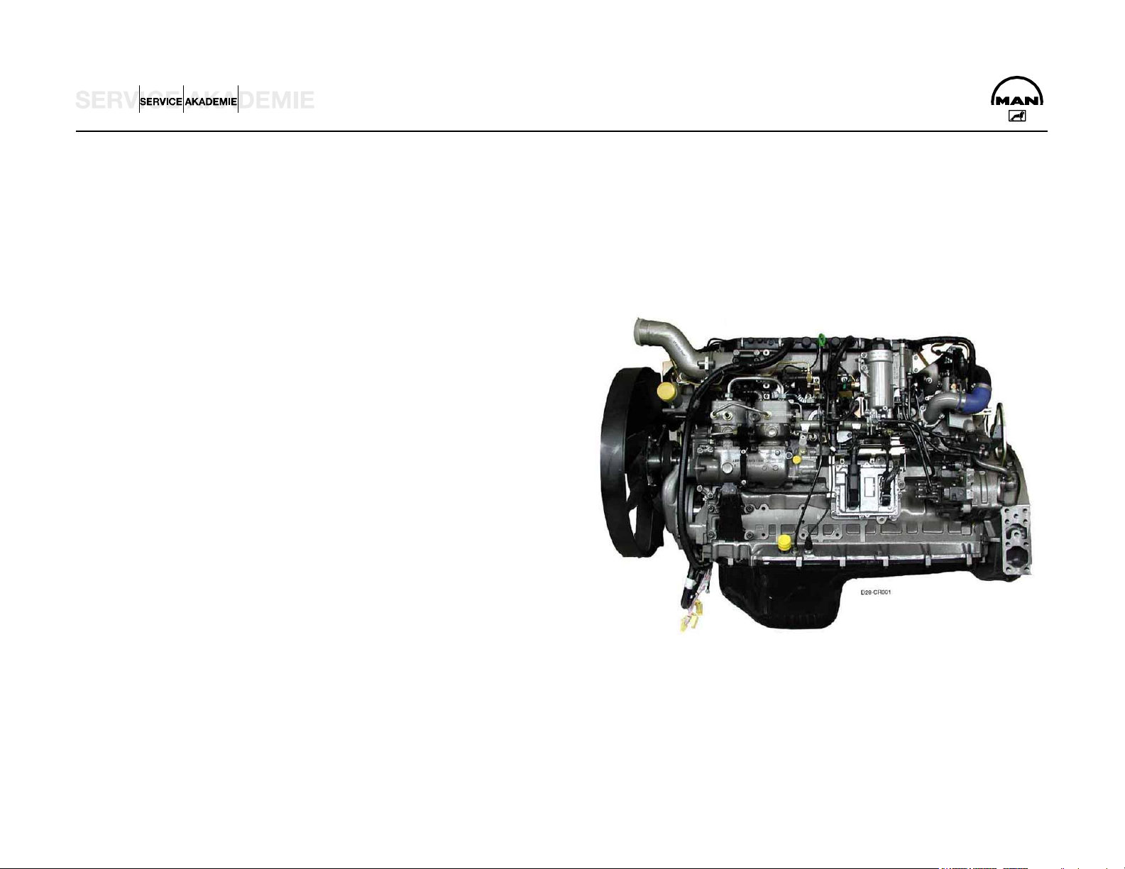
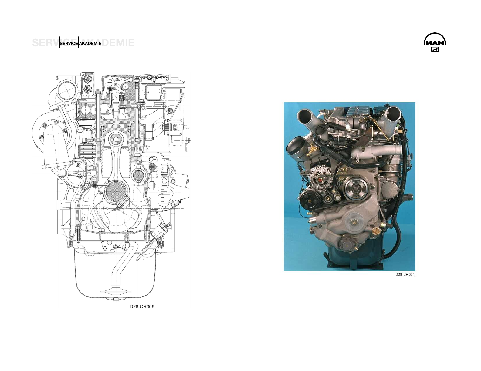
ENGINE DESCRIPTION D 2876 CR
GENERAL
The inline engines of the D 2876 LF series underwent major modification for the heavy-duty MAN Trucknology Generation (TGA):
New grading with higher power and torque plus high torque
Depending on conditions of use and lubricants, oil change
gradients
Substantial improvement of engine efficiency and fuel
consumption over wide ranges of the operating map through
an increase of engine peak pressure and the new common
rail (CR) technique
Adaptation of the cylinder head, cylinder head packing,
cylinder liner and crank case bolt fit to the higher gas
pressures
Reduced engine weight through omission of the secondary
acoustic measures and use of a lighter crank case yoke
Use of the second-generation Bosch common rail injection
system (1600 bar)
Engine management by EDC 7 and communication with the
intervals of maximally 100,000 km can be achieved and thus
lower operating costs for the user
High reliability through adherence to the proven D 2876 LF
12.8 liter engine concept
Increase of exhaust brake performance in conjunction with
the upgraded, pressure-controlled exhaust valve brake (EVB)
as special equipment
Further increase of exhaust brake performance through use
of the entirely new, innovative primary braking system water
retarder (PriTarder) in conjunction with the pressure-
controlled EVB as special equipment
vehicle management computer on the CAN bus
D:\Auto\TRUCK\MAN\MAN Series\Двигатель_Топливная система\Двигатели\en\D2876_CR_eng.doc Page 5

Changes compared to earlier D 28.. Euro 3 engines
Engine
Water pump
Crank case
Crank shaft
Connecting rods
Pistons
Cylinder liners
Cylinder heads
Cylinder head packing
Rocker arm case with rocker arm
Exhaust manifold packing
Oil pump
Oil circulation
MAN PriTarder
Fan bearing
Visco fan Eaton
Common rail injection system
EDC 7
Injectors (7-jet)
High-pressure pump with rail distribution
Sensor technology
New fuel connector system
D:\Auto\TRUCK\MAN\MAN Series\Двигатель_Топливная система\Двигатели\en\D2876_CR_eng.doc Page 6
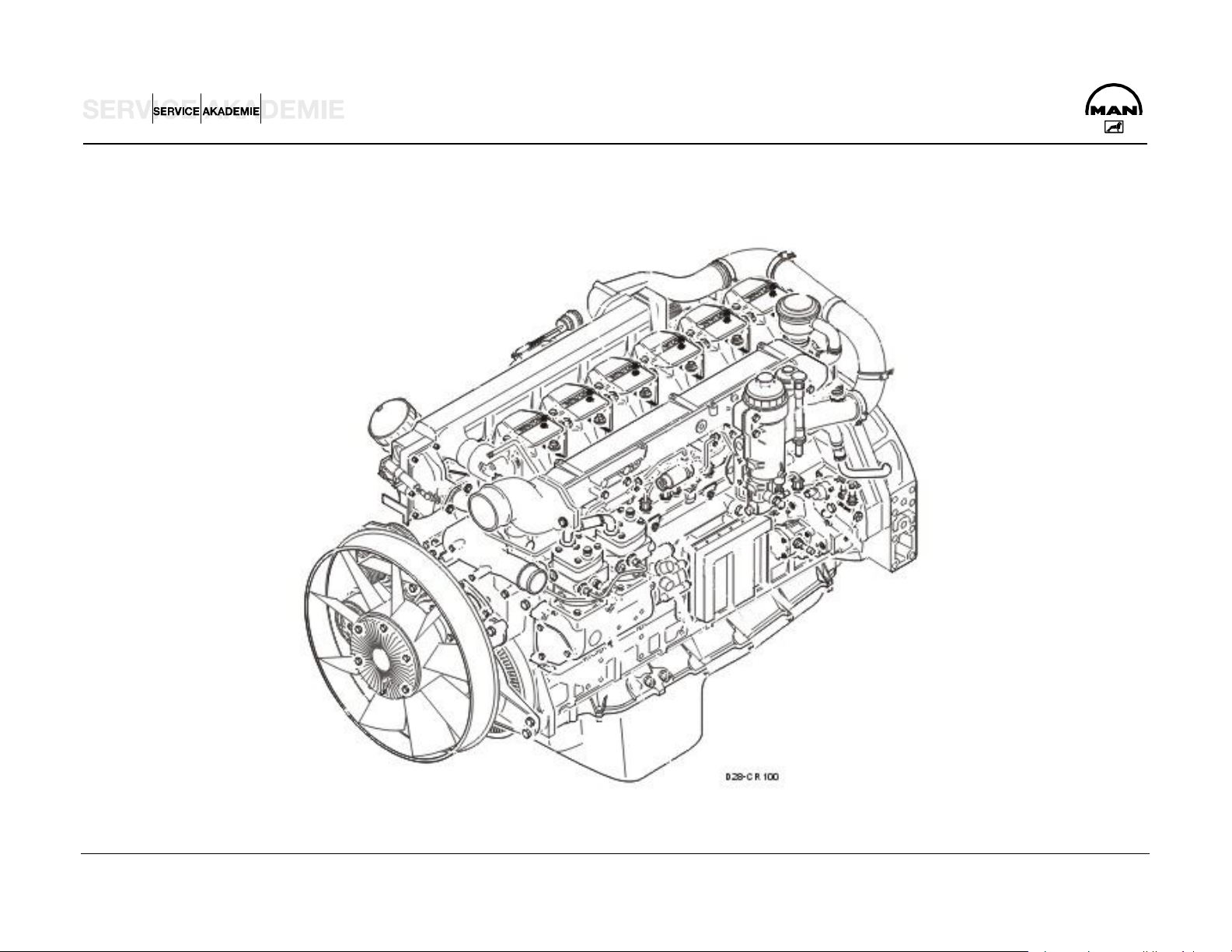
D 28.. EURO 3 COMMON RAIL
D:\Auto\TRUCK\MAN\MAN Series\Двигатель_Топливная система\Двигатели\en\D2876_CR_eng.doc Page 7

ENGINE RANGE
Engines Series Horsepower rating Chassis number
(ISO 1585-88195 EEC) starting with:
D 2876 LF 12 .............. Euro 3 ................................ TGA.........................480 hp / 353 kW .................................... WMAH..
D 2876 LF 13 .............. Euro 3 ................................ TGA.........................530 hp / 390 kW .................................... WMAH..
D:\Auto\TRUCK\MAN\MAN Series\Двигатель_Топливная система\Двигатели\en\D2876_CR_eng.doc Page 8

GENERAL EXPLANATION OF TYPE DESIGNATION
Example TGA 26o530
T Trucknology
G Generation
A -vehicle weight above 18 tons
26 Overall weight in t
530 Horsepower figure without Euro standard specification
D:\Auto\TRUCK\MAN\MAN Series\Двигатель_Топливная система\Двигатели\en\D2876_CR_eng.doc Page 9
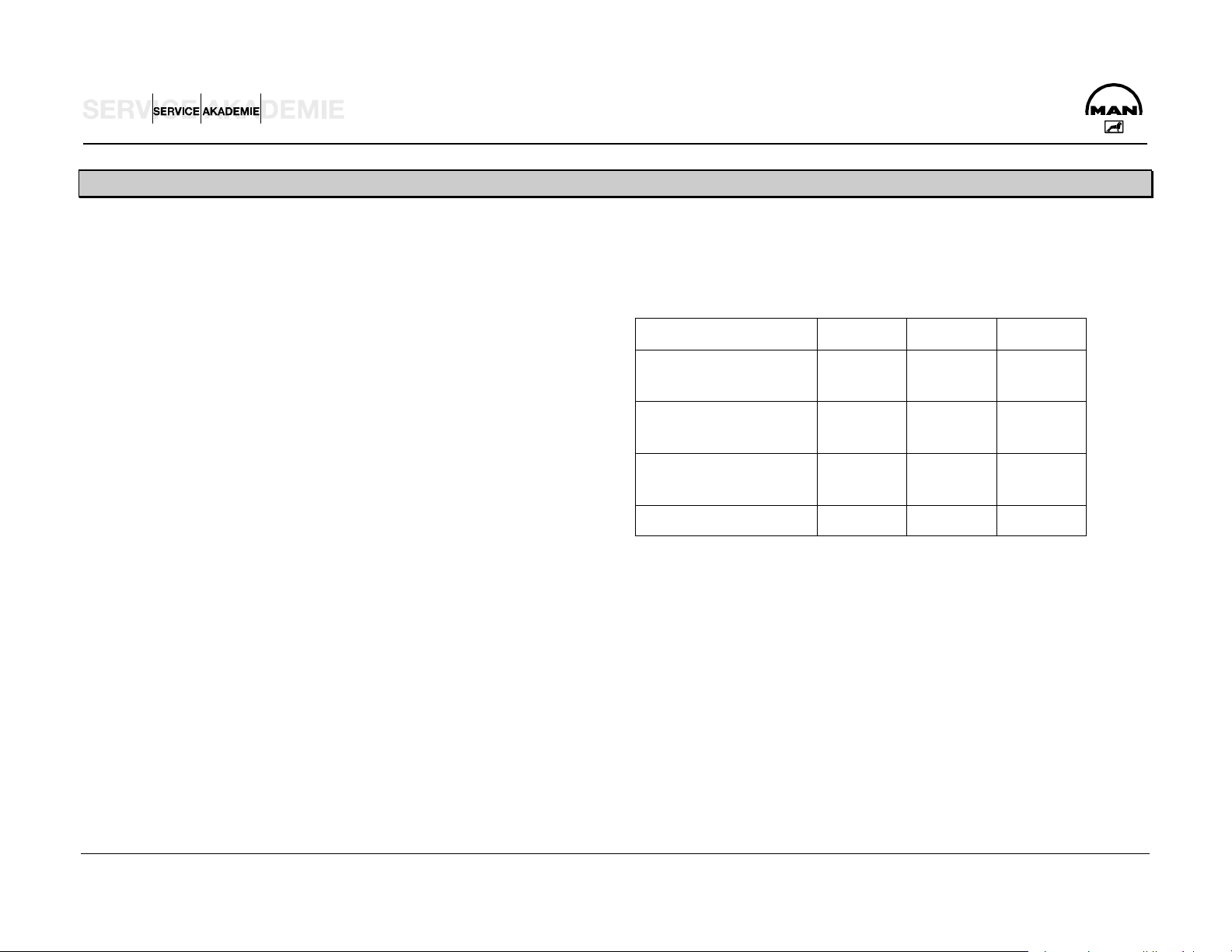
EMISSIONS – EXHAUST GAS FIGURES
In Europe the 13-step test to ECE R49 is used for commercial
vehicles of more than 3.5 t permissible overall weight.
1993 1996 2000
This means measuring the engine's exhaust emissions in 13
ready defined, stationary operating states.
Then the mean emissions are calculated.
In the procedure for Euro 3 engines, in contrast to Euro 2,
measurements will probably also be conducted in the
subdynamic and, depending on the engine version, in the full
dynamic state.
Pollutants Euro 1 Euro 2 Euro 3
CO
Carbon monoxide
HC
Hydrocarbons
NOx
Nitrogen oxide
5 4 2
1.25 1.1 0.6
9 7 5
Particles 0.4 0.15 0.1
Exhaust gas figures in g/kW/h
D:\Auto\TRUCK\MAN\MAN Series\Двигатель_Топливная система\Двигатели\en\D2876_CR_eng.doc Page 10

EXTRA EQUIPMENT
The following extra equipment is possible depending on how the customer intends to use a vehicle:
Gear wheel driven power takeoff at engine end with 600 Nm
Cooling water preheater from Calix (220 V, 1100 W)
(temporarily 720 Nm) torque
Refrigerant condenser, driven by Poly V-belt, firmly attached
to intermediate case, for vehicles with air-conditioning
Possibility of adding hydro geared pump to cam shaft power
takeoff
Possibility of adding steering pumps and hydraulic pumps on
air compressor front and rear
Ready for attachment of Frigoblock generators
G12/G17/G24 (WR is not possible here)
MAN PriTarder combination of water retarder and EVB-ec
D:\Auto\TRUCK\MAN\MAN Series\Двигатель_Топливная система\Двигатели\en\D2876_CR_eng.doc Page 11
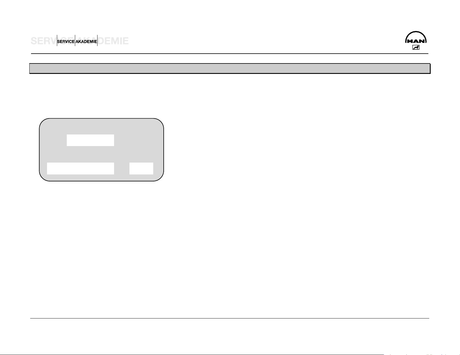
EXPLANATION OF ENGINE CODE
ENGINE TYPE LABEL
Typ
Motor-Nr. / Engine-no N I / N II
2120025200B2E1
MAN - Werk Nürnberg
D 2876 LF 12
P1
Box N I / N II
Engine type designation
D 2876 LF 12
D ...........Diesel fuel
28 ..........+100 = bore diameter, e.g. 128 mm
7 ............Stroke: 6 = 155 mm, 7 = 166 mm
6 ............Number of cylinders: 6 = 6-cylinder, 0 = 10-cylinder,
2 = 12-cylinder
L ............Turbo charger with intercooler
F............ Engine incorporation:
F Truck, forward control, vertical engine
OH Bus, rear-engined, vertical
I Deviation of 0.1 mm
II Deviation of 0.25 mm
P Big-end bearing pin
H Crank shaft bearing pin
S Follower of cam shaft (S1 0.25 mm crush)
D:\Auto\TRUCK\MAN\MAN Series\Двигатель_Топливная система\Двигатели\en\D2876_CR_eng.doc Page 12
UH Bus, rear-engined, horizontal
12 ..........Engine variant, especially important for
procuring spare parts,
technical data and settings

212
0025
200
B2E
1
G
ENGINE IDENTIFICATION NUMBER
Example:
A
A ......... 212 .............. Engine type code
B ......... 0025 ............ Date of assembly
C ......... 200 .............. Assembly sequence (progress figure on date of assembly)
D ......... B ................. Overview flywheel
E ......... 2 .................. Overview injection pump/regulation
F ......... E.................. Overview air compressor
G......... 1 .................. Special equipment like engine-governed power takeoff
B C
D E
F
D:\Auto\TRUCK\MAN\MAN Series\Двигатель_Топливная система\Двигатели\en\D2876_CR_eng.doc Page 13

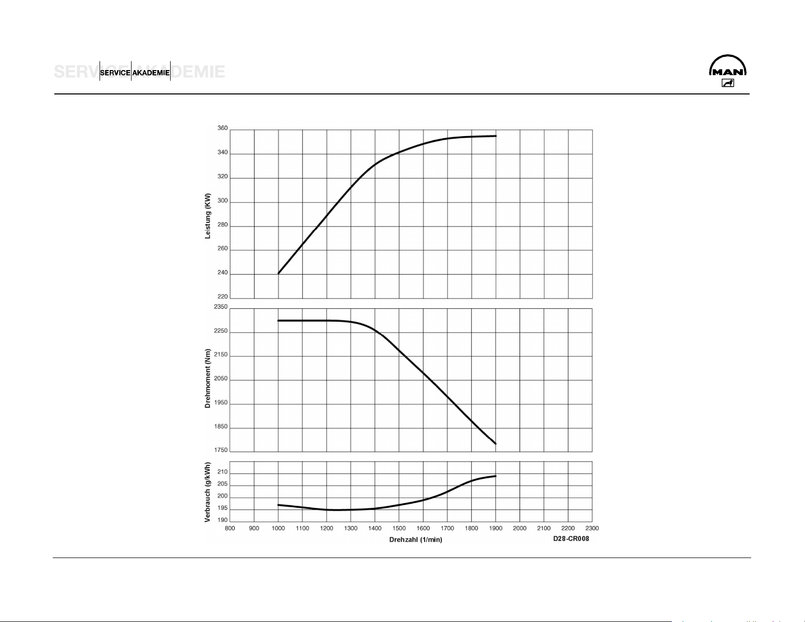
BASICS OF TORQUE
A TORQUE
C SPECIFIC FUEL CONSUMPTION
Power and torque increase with speed. After overcoming
the friction loss and greater heat losses at low speeds, the
engine achieves its maximum torque with optimum filling of
the cylinder. If speed increases further, the torque drops
because of the greater flow resistance and short valve
opening times.
B POWER
Power is the product of speed and torque. Seeing as the
drop in torque is slower than the increase in speed, there is
initially an increase if the power output of an engine.
Between the maximum torque and the maximum power
there is an elastic range in which power is kept constant
by increasing torque although the speed is dropping.
The full-load consumption curve in the diagram can be
explained by the fact that you get less than good fuel
consumption in the low range of speed because of the poor
pressure mix of the fuel particles (14.5:1). At high speeds,
combustion is imperfect because of the short time that is
available. And fuel consumption increases.
D:\Auto\TRUCK\MAN\MAN Series\Двигатель_Топливная система\Двигатели\en\D2876_CR_eng.doc Page 14
D:\Auto\TRUCK\MAN\MAN Series\Двигатель_Топливная система\Двигатели\en\D2876_CR_eng.doc Page 15

TECHNICAL DATA
D 2876 LF 12 Euro 3
Model.............................................................. R6 TI-EDC (4 V)
Idling speed .............................................................. 600 1/min
Cylinder arrangement ...................................6 cylinders inline
Max. power ..................................................... 353 kW / 480 hp
Rated speed ........................................................... 1900 1/min
Max. torque.................................................................2300 Nm
Speed at max. torque.................................1000 to 1300 1/min
Capacity.................................................................. 12,816 cm3
Bore / stroke ...............................................................128 / 166
Ignition sequence ................................................... 1-5-3-6-2-4
Cylinder 1 location ....................................................... fan side
Combustion process, injector ............................................ 7-jet
Compression..........................................................................18
Valve play on cold engine .......................................IV 0.50 mm
Valve play exhaust with EVB ..............EV 0.80 mm / 0.60 mm
Compression pressure.................................................> 28 bar
Admissible pressure difference between cylinders ..max. 4 bar
Coolant ...........................................................50 (I/R 58) liters
Oil charge ....................................................................42 liters
Fuel system.........................................................Bosch EDC 7
Fan coupling actuation........................................hydroelectric
Weight (dry) with WR................................................... 1071 kg
K factor........................................................................... 1.3 m-1
D:\Auto\TRUCK\MAN\MAN Series\Двигатель_Топливная система\Двигатели\en\D2876_CR_eng.doc Page 16
D:\Auto\TRUCK\MAN\MAN Series\Двигатель_Топливная система\Двигатели\en\D2876_CR_eng.doc Page 17

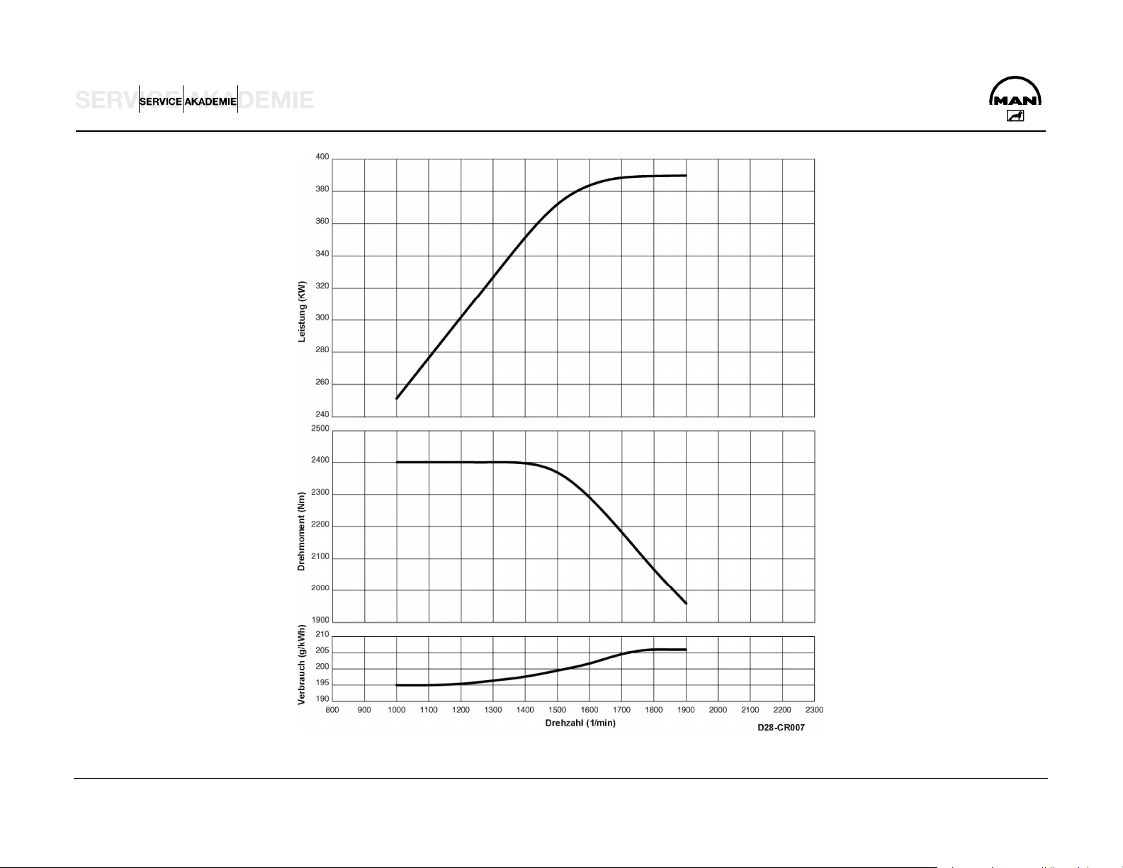
D 2876 LF 13 Euro 3
Model.............................................................. R6 TI-EDC (4 V)
Idling speed .............................................................. 600 1/min
Cylinder arrangement ...................................6 cylinders inline
Max. power ..................................................... 390 kW / 530 hp
Rated speed ........................................................... 1900 1/min
Max. torque.................................................................2400 Nm
Speed at max. torque.................................1000 to 1400 1/min
Capacity.................................................................. 12,816 cm3
Bore / stroke ...............................................................128 / 166
Ignition sequence ................................................... 1-5-3-6-2-4
Cylinder 1 location ....................................................... fan side
Combustion process, injector ............................................ 7-jet
Compression..........................................................................18
Valve play on cold engine .......................................IV 0.50 mm
Valve play exhaust with EVB ..............EV 0.80 mm / 0.60 mm
Compression pressure.................................................> 28 bar
Admissible pressure difference between cylinders ..max. 4 bar
Coolant ...........................................................50 (I/R 58) liters
Oil charge ....................................................................42 liters
Fuel system.........................................................Bosch EDC 7
Fan coupling actuation........................................hydroelectric
Weight (dry) without WR.............................................. 1049 kg
K factor........................................................................... 1.3 m-1
D:\Auto\TRUCK\MAN\MAN Series\Двигатель_Топливная система\Двигатели\en\D2876_CR_eng.doc Page 18
D:\Auto\TRUCK\MAN\MAN Series\Двигатель_Топливная система\Двигатели\en\D2876_CR_eng.doc Page 19

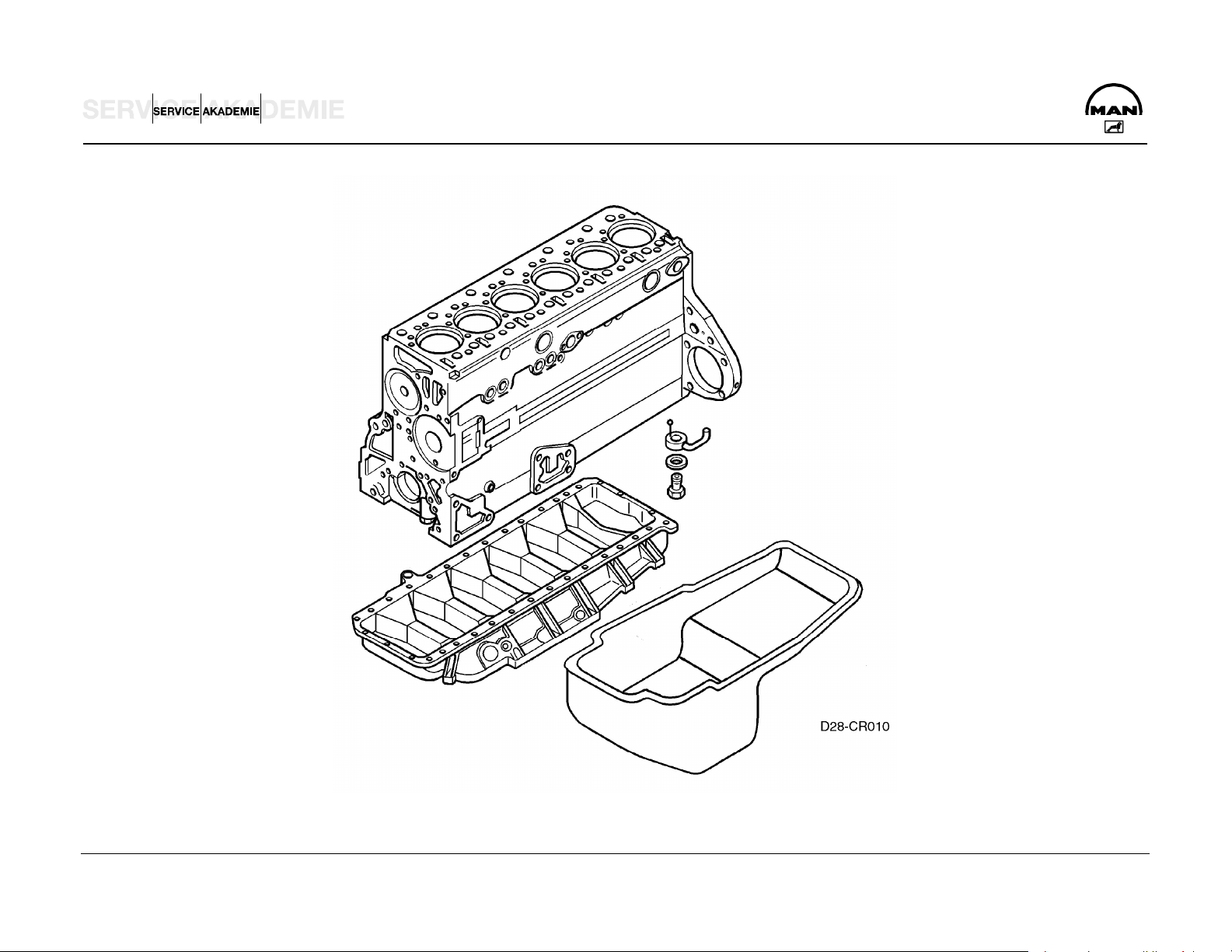
ENGINE BLOCK – CRANK CASE
The crank case is cast in one piece together with the cylinder
block from special GJL-250 cast iron. The wet cylinder liners of
highly wear-resistant, special centrifugal cast GJL-250 are
exchangeable. The sealing between the cylinder liner and the
crank case coolant jacket at the top is by a oval elastomer
moulded washer and at the bottom by two elastomer round
sealing rings.
Optimized wall thicknesses and functional ribbing of the crank
case side walls optimized by the finite element method (FEM)
produce rigidity of form and low noise emission.
The crank case was matched to the higher ignition pressure
(160 instead of 145 bar) by reinforcing the partitions and
geometrically optimizing the cylinder liner fitting, but for the
same crank case weight.
The crank case was matched externally for compact attachment
of the new EDC 7 control unit, rail and cam shaft engine speed
sensor. The casting and machining of the crank case were also
optimized.
The crank case is closed off at the rear by the flywheel/timing
case of GJS-400 ductile cast iron, with the rear crank shaft
sealing ring, and at the bottom by the crank case yoke of
permanent mould cast aluminium (Loctite 518 sealing). Apply a
track with a maximum width of 1 mm.
The crank case venting gases are fed back into the combustion
air by way of a wire-knit oil trap with pressure regulating valve
attached to the rear left of the crank case to avoid emission on
the intake side of the turbo charger.
To improve the oil supply to the valve gear, extra oil holes were
provided in the crank case across from the main oil duct through
the partitions to the cam shaft bearing (and on to the valve
gear).
D:\Auto\TRUCK\MAN\MAN Series\Двигатель_Топливная система\Двигатели\en\D2876_CR_eng.doc Page 20
D:\Auto\TRUCK\MAN\MAN Series\Двигатель_Топливная система\Двигатели\en\D2876_CR_eng.doc Page 21

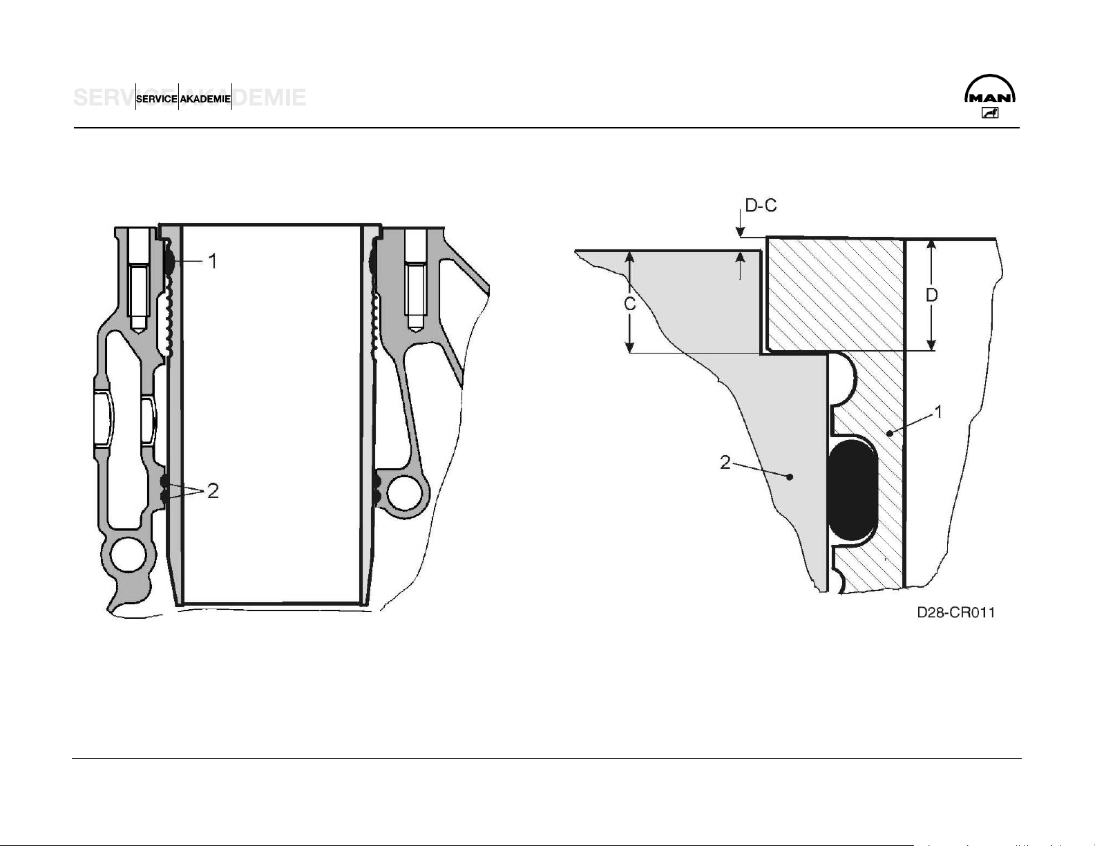
CYLINDER LINERS
The wet, exchangeable cylinder liners are produced from a
NOTE:
special centrifugal cast iron.
The oval O-ring (1) for the upper packing must be inserted
without any twist in the second grooves of the liner.
Lightly coat the cylinder liner in the region of the upper O-ring
with engine oil.
Place new O-rings (2) in the crank case (Viton).
Lightly coat the region of the lower O-ring with engine oil, as well
as the transition of the cylindrical part of the bush.
Caution:
Do NOT use a brush!
NOTE:
The packing of the cylinder liners is different.
DO NOT USE ANY KIND OF GREASE / SEALANT.
Method for measuring cylinder liner projection (without the
sealing ring). Place cylinder liners in the crank case without an
O-ring.
Attach a press-on gauge plate and tighten to 40 Nm. Then
measure at at least four points with the dial gauge.
1 Cylinder liner
2 Crank case
C Rim depth in crank case
D Rim height of cylinder liner
D-C Projection of liner from crank case
Cylinder liner projection: min 0.035 mm, max. 0.1 mm
Rim depth C 7.965 to 8.015 mm
Rim height of cylinder liner D 8.05 to 8.07 mm
D:\Auto\TRUCK\MAN\MAN Series\Двигатель_Топливная система\Двигатели\en\D2876_CR_eng.doc Page 22
D:\Auto\TRUCK\MAN\MAN Series\Двигатель_Топливная система\Двигатели\en\D2876_CR_eng.doc Page 23

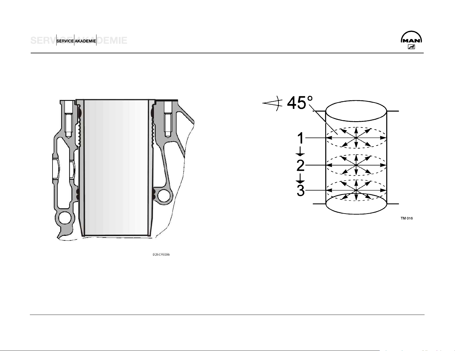
PISTON PLAY – CYLINDER LINERS
Measurement of piston play:
NOTE:
Measure the inner diameter of the cylinder liners with an inside
micrometer at three levels from top to bottom, and radially at
intervals of 45°. Read the piston diameter from the bottom of
new pistons. On pistons that have run, measure with an outer
micrometer from the piston bottom edge across the piston axis.
Subtract the piston diameter from the largest measured cylinder
liner diameter.
The figure arrived at is the piston play.
If the piston play is too large, replace the cylinder bush and
piston.
Example of piston play for D 28..LF
Cylinder diameter......................................127.99 to 128.01 mm
Piston diameter. ....................................127.561 to 127.570 mm
Ideal play ..........................................................0.14 to 0.15 mm
Wear limit...................................................................... 0.30 mm
Measure on 3 position, for example 1,2,3
D:\Auto\TRUCK\MAN\MAN Series\Двигатель_Топливная система\Двигатели\en\D2876_CR_eng.doc Page 24
D:\Auto\TRUCK\MAN\MAN Series\Двигатель_Топливная система\Двигатели\en\D2876_CR_eng.doc Page 25

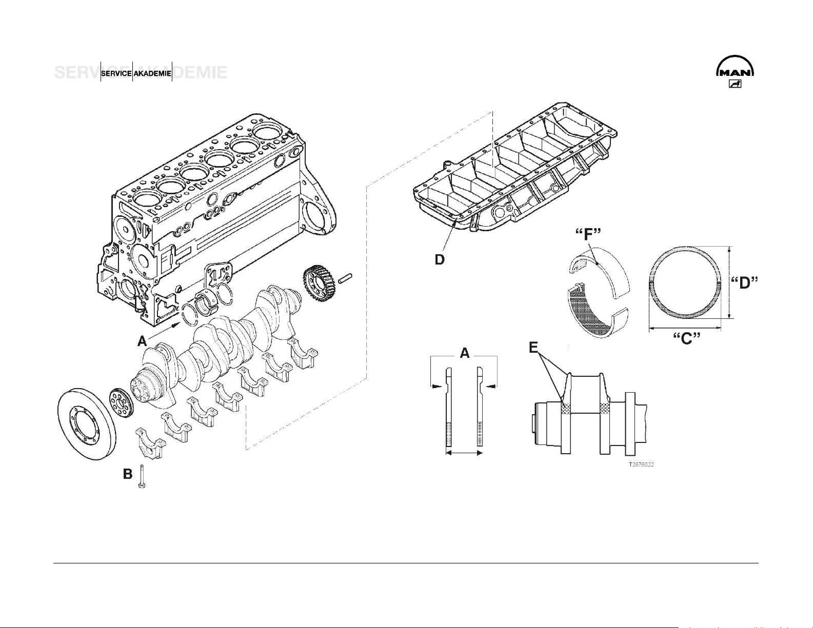
CRANK SHAFT
The crank shaft has a 7-point bearing and eight forged-on
A Axial bearing of crank shaft............ 0.190 to 0.312 mm
counterweights to balance inertial forces. The main and big-end
bearing pins as well as the lapped bearing collars are induction
hardened and ground.
ON A CRANK SHAFT N1, ALL BIG-END OR MAIN BEARING
PINS ARE IN EVERY CASE ALSO N1.
The axial bearing of the crank shaft is implemented by thrust
washers on the middle bearing block.
Attention: The oil flutes of the thrust washers A must face the
crank webs.
Attention: Never dismantle the vibration damper using a
hammer or fitter's lever. The slightest dent will ruin the damping
function of the vibration damper. This can cause clutch damage
and breakage of the crank shaft.
Wear limit............................................................. max. 1.25 mm
B Main bearing bolts.................................... 300 Nm + 90°
D Crank case yoke to reinforce crank case
Use 04.10394-9272 sealant.
E Designation H and P tolerance N or N1 of big-end or main
bearing pins (N1= 0.1 mm deviation)
Spread of bearing shells F:
Measure dimension C.
Measure dimension D.
Expansion = C minus D
Spread must be between 0.3 and 1.2 mm.
Attention: C must be greater than D.
Main bearing pin diameter .................... N 103.98 to 104.00 mm
Main bearing inner diameter ............. N 104.066 to 104.112 mm
Other undersizes.................. 0.25 to 0.50 mm, 0.75 to 1.00 mm
D:\Auto\TRUCK\MAN\MAN Series\Двигатель_Топливная система\Двигатели\en\D2876_CR_eng.doc Page 26
D:\Auto\TRUCK\MAN\MAN Series\Двигатель_Топливная система\Двигатели\en\D2876_CR_eng.doc Page 27

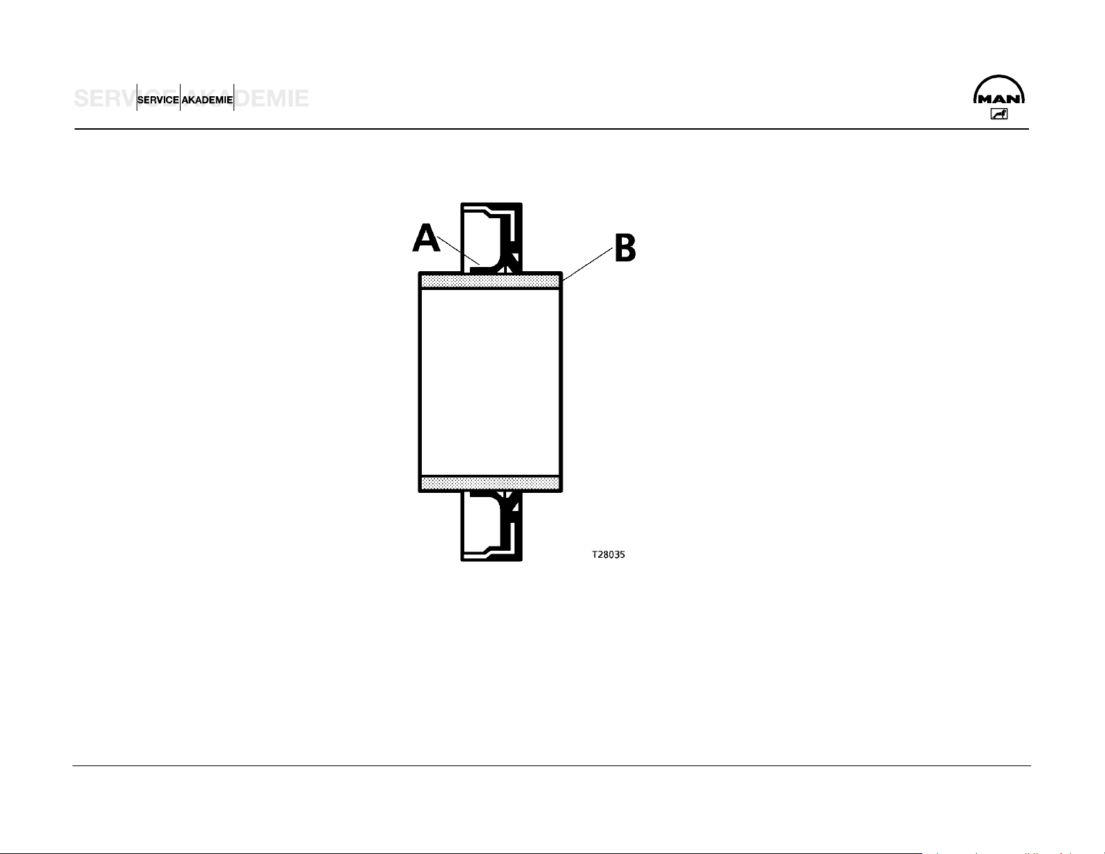
Crank shaft lining front and rear
On the rear crank shaft lining, like on the front, rotary shaft
Fitting notes:
seals of polytetrafluorethylene (PTFE), trade name Teflon, are
always used.
Because of its own relatively large initial tension, the lip (A)
tends to curve inwards. For this reason the PTFE lining ring is
supplied on a transport wrapper (B). It must be left on this
wrapper until it is used. Another reason for this is that the lip is
very sensitive and the slightest damage can result in leakage.
The sealing lip and the race of the flywheel must not be coated
with oil or other lubricants.
NOTE:
New engines come without a race.
When repairing, only use variants with a race (04.10160-9049
The PTFE lining ring must be fitted absolutely free of oil
and grease. The slightest oil or grease traces on the race or
lining ring can result in leakage.
Before fitting, clean any oil, grease and anti-corrosion agents
off the race and pull-in tool. You can use any conventional
cleaning agent for this purpose.
Never store the PTFE lining ring without the supplied
transport wrapper. After only about 20 min without the
wrapper it will lose its initial tension and is then unusable.
sealant).
D:\Auto\TRUCK\MAN\MAN Series\Двигатель_Топливная система\Двигатели\en\D2876_CR_eng.doc Page 28
D:\Auto\TRUCK\MAN\MAN Series\Двигатель_Топливная система\Двигатели\en\D2876_CR_eng.doc Page 29

Pull out the rotary shaft seal
Loosen the lining ring by tapping it.
Use the extractor tool
Slide the four hooks under the lip, turn through 90° so that they
grip the ring behind the lip, and pull out the rotary shaft seal by
turning the spindle.
Attach the race
The latest crank shafts come without races. A race is fitted
when renewing the crank shaft sealing ring.
Clean the inside of the race and crank shaft stump, and coat the
crank shaft stump with 04.10160-9049 sealant. Slide the race
and press-fit sleeve onto the adapter. Tighten the spindle in the
adapter with the nut. Screw the adapter tightly to the crank shaft.
The adapter must fit tightly on the crank shaft to ensure the
Fit the rotary shaft seal
Screw the adapter to the crank shaft.
Clean the adapter and the race. The rotary shaft seal must be
assembled dry. Do not coat the lips with oil or other
lubricants.
Place the rotary shaft seal with the transport wrapper on the
adapter and slide the seal onto the adapter.
Remove the transport wrapper.
Slide the winding sleeve onto the adapter.
Screw the spindle into the adapter.
Pull in the rotary shaft seal as far as the stop of the winding
sleeve on the end cover.
correct press-fit depth of the race. Pull in the race as far as the
stop of the press-fit sleeve.
D:\Auto\TRUCK\MAN\MAN Series\Двигатель_Топливная система\Двигатели\en\D2876_CR_eng.doc Page 30

D:\Auto\TRUCK\MAN\MAN Series\Двигатель_Топливная система\Двигатели\en\D2876_CR_eng.doc Page 31

FLYWHEEL
The flywheel is centered on the crank shaft by a set pin and
Caution:
attached by ten torque screws.
Tightening method for flywheel screws
Anti-fatigue screws M16 x 1.5 (12.9)
Pretighten to 100 Nm.
Turn 900.
Tighten finally by turning 90°.
NOT reusable
Make sure the race (2) is properly seated.
Use 04.10160-9049 sealant.
Place the faced side first and use a mandrel to push it right on.
Coat the seat of the race with green Omnifit.
Clutch shaft guide bearing (1)
D:\Auto\TRUCK\MAN\MAN Series\Двигатель_Топливная система\Двигатели\en\D2876_CR_eng.doc Page 32

D:\Auto\TRUCK\MAN\MAN Series\Двигатель_Топливная система\Двигатели\en\D2876_CR_eng.doc Page 33

Machining of flywheel
In the event of heavy scoring, the permissible material wear of
Maximal lateral runout of starter rim: 0.5 mm
the press-on surface is max. 1,6 mm.
Minimum dimension A: 60.5 mm
Standard dimension A: 62 ±0.1 mm
Outer diameter of flywheel: 488 to 487.8 mm
The starter rim is heated to between 200 and 230°C for
assembly.
D:\Auto\TRUCK\MAN\MAN Series\Двигатель_Топливная система\Двигатели\en\D2876_CR_eng.doc Page 34

D:\Auto\TRUCK\MAN\MAN Series\Двигатель_Топливная система\Двигатели\en\D2876_CR_eng.doc Page 35

CONNECTING ROD
The connecting rods are drop-forged from heat-treatable
C38mod steel, without weight compensating battens, and split
obliquely by cracking the bearing cap. The oblique split
NOTE:
The top bearing shell is marked TOP or has a red spot on the
side (tempered backing shell).
simplifies assembly and repair, because the connecting rods can
be taken out through the top of the cylinders.
The big-end bearings are designed for extremely high stress and
long service life. The upper bearing shell consists of highly
wear-resistant sputter metal. There is a long oil hole from the
large to the small connecting rod eye for proper supply of oil to
the latter.
Measurement of big-end bearing
Measure the inner bore of the big-end bearing shells in an
assembled state on the axes 1, 2 and 3 and at levels a and b.
Bearing shells whose bore is within tolerance limits can be re-
used, if they are outside you must renew the bearing.
Scrap them if the bore is larger or oval.
Big-end bearing pin dia. (standard). .........89.980 to 90.000 mm
Big-end bearing inner dia. (standard) .......90.060 to 90.102 mm
Big-end bearing spread (Miba) .........................95.5 to 96.4 mm
Big-end bearing radial play ...........................0.060 to 0.122 mm
Spread C...........................................................95.5 to 96.4 mm
Tightening torque of connecting rod screws:
100 Nm
+10
+ 90°
+10
Connecting rod screws: M14 x 1.5 x 65/10.9 Torx
Re-use of the screws is not permissible.
Caution:
Do NOT place the connecting rod or the cover on the seam.
Any damage (change) to the structural fracture will destroy
it.
D:\Auto\TRUCK\MAN\MAN Series\Двигатель_Топливная система\Двигатели\en\D2876_CR_eng.doc Page 36

D:\Auto\TRUCK\MAN\MAN Series\Двигатель_Топливная система\Двигатели\en\D2876_CR_eng.doc Page 37

PISTONS
The three-ring pistons are of a special cast aluminium with a
moulded ring insert for the uppermost piston ring. The combustion
chamber is slightly retracted, graduated and omega-shaped.
There are valve recesses on the inlet and outlet side. To reduce
the effects of heat, the pistons have a cast integral cooling duct
and are cooled by an oil jet from injection nozzles.
The pistons were adapted to the higher ignition pressures by
graduated bracing of the connecting rod, suitable selection of
materials and appropriate scaling of the combustion chamber.
The oil injection nozzles in the crank case are matched in their
flow cross-section to the new cooling duct of the pistons. The oil
pressure valve in the injection nozzles is omitted to ensure proper
piston cooling also at low engine speeds.
A new, smooth piston pin of larger diameter is used to take load
off the piston pin boss.
Rings
Double-faced trapezoidal ring and second compression ring as
compression rings, ventilated oil scraper ring with spiral expander
and bevelled outer edges.
Piston projection under/over top edge of crank case:
-0.03 to +0.331 mm
Gap of piston rings, wear limit
I Trapezoidal ring, wear limit 1.5 mm
II Second compression ring, wear limit 1.5 mm
III Oil scraper ring, wear limit 1.5 mm
D:\Auto\TRUCK\MAN\MAN Series\Двигатель_Топливная система\Двигатели\en\D2876_CR_eng.doc Page 38

D:\Auto\TRUCK\MAN\MAN Series\Двигатель_Топливная система\Двигатели\en\D2876_CR_eng.doc Page 39

Pistons (technical data from Kolben Schmidt)
1 Piston diameter, measured across boss:
KS measured 20 mm
above piston bottom edge (2)......... 127.561 to 127.570 mm
4 Compression height:
Standard dimension: D 2876 LF........................... 79.25 mm
Undersize: 0.2 mm / 0.4 mm / 0.6 mm
A Piston projection under/over crank case top edge:
- 0.03 to +0.30 mm
Piston ring flutes
(5) Compression ring 1 .........................................4 to 4.05 mm
(6) Compression ring 2 ....................................3.04 to 3.06 mm
Piston ring height
Double-faced trapezoidal compression ring
Height .......................................................3.99 to 4.025 mm
Gap.............................................................0.35 to 0.55 mm
Second compression ring ...................................2.97 to 3.0 mm
Gap.................................................................0.7 to 0.9 mm
Oil scraper ring
KS.............................................................3.975 to 3.99 mm
Gap.............................................................0.25 to 0.55 mm
Piston weight difference per engine set...................... max. 50 g
Fit with arrow pointing to the frontend
(7) Oil scraper ring.......................................... 4.04 to 4.06 mm
D:\Auto\TRUCK\MAN\MAN Series\Двигатель_Топливная система\Двигатели\en\D2876_CR_eng.doc Page 40

D:\Auto\TRUCK\MAN\MAN Series\Двигатель_Топливная система\Двигатели\en\D2876_CR_eng.doc Page 41

ENGINE CONTROL
Setting of timing
The marking of the crank shaft gear must match with the marking
of the shrink-fit cam shaft gear (not the same as TDC of
cylinder 1).
A Gear wheels on flywheel side
1 Crank shaft
2 Oil pump drive
3 Oil pump delivery wheels
4 Cam shaft
5 Intermediate gear for high pressure pump
6 High pressure pump drive
7 Auxiliary drive
B Gear wheels on fan side
8 Cam shaft wheel
9 Compressor drive gear
10 Fan drive gear
D:\Auto\TRUCK\MAN\MAN Series\Двигатель_Топливная система\Двигатели\en\D2876_CR_eng.doc Page 42

D:\Auto\TRUCK\MAN\MAN Series\Двигатель_Топливная система\Двигатели\en\D2876_CR_eng.doc Page 43

CAM SHAFT
The cam shaft is forged from Cf53 steel with induction hardened
The cam shaft is driven from the crank shaft by case-hardened,
and ground cams and bearing points. It is seated in the crank
case with a 7-point bearing in white metal bushes. The axial
bearing of the cam shaft takes the form of a collar end bearing in
the crank case on bearing 7. In the timing case there is a butting
ring screwed in as an axial stop.
Engines with cam shaft power takeoff are fitted with a specially
forged shaft of carburizing 16MnCr5 steel with a highly wear-
resistant, sputter collar end bearing 7 in the crank case.
helically toothed spur wheels on the rear side of the engine.
Bolted at the back of the cam shaft is also the drive wheel for
high-pressure pump CP3.4 (M10 x 35 10.9 Nm 65). This gear
wheel bears markings for the cam shaft engine speed sensor.
Valve lifter lubricant paste 09.15011-0011.
A spur wheel is fitted to the front end of the cam shaft to drive
the air compressor and the fan shaft.
1 Reference markers to identify first cylinder
2 High-pressure pump drive wheel
3 Cam shaft drive wheel
4 Retaining screw 65 Nm
5 Oil hole
D:\Auto\TRUCK\MAN\MAN Series\Двигатель_Топливная система\Двигатели\en\D2876_CR_eng.doc Page 44

D:\Auto\TRUCK\MAN\MAN Series\Двигатель_Топливная система\Двигатели\en\D2876_CR_eng.doc Page 45

Admissible play of cam shaft
Measure the axial play of the cam shaft.
Cam shaft axial play .......................................0.20 to 0.90 mm
Wear limit ................................................................... 1.50 mm
Test without the air compressor attached.
NOTE:
For cam shaft power takeoff, the cam shaft is held reinforced
between bearings 6 and 7 and in a highly wear-resistant,
special collar end bearing on bearing 7.
Tightening torque:
Screws for butting ring 40 Nm
Secure with Loctite 648.
Press the cam shaft tightly against the crank case.
Add the seal thickness z = 0.5 mm to dimension y.
Cam shaft axial play = y + z - x
Dimension x = margin of sealing face of crank case
to butting face of cam shaft drive wheel
Dimension y = margin of sealing face of timing case
to butting ring
Dimension z = thickness of seal pressed
1 Crank case
2 Gauge rail
3 Cam shaft gear wheel
4 Sealing face of crank case
5 Sealing face of timing case
6 Butting ring
7 Timing case
D:\Auto\TRUCK\MAN\MAN Series\Двигатель_Топливная система\Двигатели\en\D2876_CR_eng.doc Page 46

D:\Auto\TRUCK\MAN\MAN Series\Двигатель_Топливная система\Двигатели\en\D2876_CR_eng.doc Page 47

CHECK OF VALVE TIMING
Check the timing for the specified valve cycle.
Twisting of the shrink-fit cam shaft drive wheel can result in
serious engine damage.
Consequently, after engine malfunctions that can cause such
twisting, e.g. failure of the air compressor, make sure seating is
correct by checking the valve timing.
Requirement: push roads must not be bent.
D 2876 LF 12 0.50 IV / 0.60 EV / 0.40 EVB Valve play
Valve travel 9.0 to 9.5 mm
D 2876 LF 13 0.50 IV / 0.60 EV / 0.40 EVB Valve play
Valve travel 9.0 to 9.5 mm
Proceed as follows:
Attach the engine turning gear to the timing case.
Remove the cylinder head.
Correctly set the inlet and exhaust valves.
Set the flywheel to TDC so that the valves overlap.
Place the dial gauge with approx. 11 mm advance on the
disk of the inlet valve on the 4th cylinder and set to "O".
Turn the engine in the running direction (left) until the dial
gauge pointer no longer moves.
If the timing is correct, the figures shown on the dial
gauge must be within the following tolerances.
Read the valve travel from the dial gauge.
.
D:\Auto\TRUCK\MAN\MAN Series\Двигатель_Топливная система\Двигатели\en\D2876_CR_eng.doc Page 48

D:\Auto\TRUCK\MAN\MAN Series\Двигатель_Топливная система\Двигатели\en\D2876_CR_eng.doc Page 49

Timing
Timing D 2876 LF 12/13
Inlet opens 23° before TDC
Inlet closes 12° after BDC
Exhaust opens 60° before BDC
Exhaust closes 30° after TDC
Timing diagram
Degrees referred to crank shaft angle
1 = Direction of engine turning
2 = Inlet opens
3 = Inlet closes
4 = Inlet opening time
5 = Center inlet cam
6 = Exhaust opens
7 = Exhaust closes
8 = Exhaust opening time
9 = Center exhaust cam
D:\Auto\TRUCK\MAN\MAN Series\Двигатель_Топливная система\Двигатели\en\D2876_CR_eng.doc Page 50

1
5
2
1
5
2 7 0
BDC
4
TDC
7
2
°
3
2
3
0
°
9
°
0
6
1
2
°
6
3
D:\Auto\TRUCK\MAN\MAN Series\Двигатель_Топливная система\Двигатели\en\D2876_CR_eng.doc Page 51

CYLINDER HEAD AND VALVE GEAR
The engines have cylinder heads of special GJL-250 cast iron,
NOTE:
with cast integral, swirl inlet and exhaust ports, shrunk-in inlet
and exhaust valve seat rings, and press-fit, exchangeable valve
tracks.
The cylinder heads were adapted to the higher ignition pressure
by reinforcing the baseplate and using smaller valve diameters.
To increase the prestressing force, the cylinder heads are now
each attached to the crank case by six larger, high-strength Torx
collar screws with an M16 x 2 thread.
New steel cylinder head seal inserts were developed for D 2876
LF 12/13 engines, with a newly designed seal plus drain moved
forward to the combustion chamber, elastomer seals on the fluid
ports and an elastomer seal on the outer contour.
.
D:\Auto\TRUCK\MAN\MAN Series\Двигатель_Топливная система\Двигатели\en\D2876_CR_eng.doc Page 52

D:\Auto\TRUCK\MAN\MAN Series\Двигатель_Топливная система\Двигатели\en\D2876_CR_eng.doc Page 53

CYLINDER HEAD ATTACHMENT
The cylinder head is attached to the crank case with the fluid
sealed rocker arm case by six Torx screws. The cylinder head
screws (dia. 16 mm) have spacers and a thread in the top
region. This thread serves for better tracking and centering
between cylinder head and rocker arm case.
NOTE:
Use Loctite 5900 or 5910 sealant between the rocker arm
bearing case and the cylinder head.
Use 09.16012-0017 paste.
Length of cylinder head screws:
Bold with fixed shim (2,3,5) 227,5 mm
Bold with fixed shim (1,4,6) 285,3 mm
Bold with unfixed shim (2,3,5) 225,8 mm
Screws with Torx head
1) Fit the cylinder heads, align them and tighten the screws to
10 Nm (paint the screw heads with Optimol White and oil
the threads).
2) Pretighten to 80 Nm.
3) Pretighten to 150 Nm.
4) Pretighten to 90°
5) Finally tighten to 90°
+10
.
+10
.
NOTE:
Retightening of the cylinder head screws is no longer necessary.
Bold with unfixed shim (1,4,6) 287,3 mm
D:\Auto\TRUCK\MAN\MAN Series\Двигатель_Топливная система\Двигатели\en\D2876_CR_eng.doc Page 54

D:\Auto\TRUCK\MAN\MAN Series\Двигатель_Топливная система\Двигатели\en\D2876_CR_eng.doc Page 55

4V Cylinder Head Inlet and Exhaust Valve Side
The inlet and exhaust valves are friction clamped by the three
C Valve cover
grooves in the stem and the cotters. There are stem seals on all
valves to minimize oil consumption. Valves are actuated by the
bridge of the rocker arm. Make sure the bridge is correctly fitted.
The milled face of the bridge is towards the push rod.
The inlet valve only differs slightly from the exhaust valve.
Distinguishing feature: spherical recess (B) of small diameter
in the valve disk from the inlet valve.
Inlet valve diameter 44 mm
Exhaust valve diameter 41 mm
The inlet valve retrusion is 0.60 0.2 mm.
The exhaust valve retrusion is 0.69 0.2 mm.
The EVB mechanism is incorporated in the exhaust valve
bridge (3). The oil supply of the rocker arms and the EVB is
through the rocker arm bearing case. The EVB arrester is
integrated into the rocker arm bearing case.
D Bridge
E Setting screw
F Check nut
G Inlet valve setting (0.50 mm)
1 Valve steam seal
2 Retaining screw
3 Exhaust valve bridge
4 Setting screw EVB (0.6 mm)
5 Check nut EVB (tighten to 40 Nm)
6 Setting screw with elephant foot (0.80 mm)
7 Check nut (tighten to 40 Nm)
Inlet valve seat 120°
Exhaust valve seat 90°
D:\Auto\TRUCK\MAN\MAN Series\Двигатель_Топливная система\Двигатели\en\D2876_CR_eng.doc Page 56

D:\Auto\TRUCK\MAN\MAN Series\Двигатель_Топливная система\Двигатели\en\D2876_CR_eng.doc Page 57

REMOVAL AND FITTING OF INJECTORS
Removal of injector
1. Undo the injection lead and cover up the pipe.
2. Undo and remove the screw for the pad.
3. Take out the pressure pipe stub using a special-purpose tool.
4. Remove the cheese-head screw of the pressure flange.
5. Pull out the injector using a special-purpose tool and keep it
in a safe place (not above the pressure flange).
3) Tighten the injector cheese-head screw (5) to 25 Nm +
90°.
4) Tighten the pad for the pressure pipe stub,
screw (8) 20 Nm + 90°.
5) Connect the high-pressure lines from and to the rail.
- Tighten the retaining screws of the rail (hand tight).
- Tighten the nuts of new high-pressure lines
to 10 Nm + 60° (not reuseable)
- Tighten the retaining screws of the rail.
NOTE:
The pressure pipe stub must not be used again after removal,
6) Tightening torque for electrical connection M4 1.5 Nm.
1 O-ring (grease)
and always use new O-rings and a Cu gasket (1.5 mm).
2 Copper gasket
Fitting of injector
3 Retaining pressure flange
Do not remove the protective cap until immediately before fitting
4 Spherical washer
the injector in the engine.
5 Pressure flange screw
1) Pretighten the injector with the pressure flange (ensure
correct position) with the cheese-head screw (5) M8 x 55
10.9 in the cylinder head to 1 to 2 Nm.
2) The thinner end (10) of the pressure pipe stub must face
the injector. Pretighten the cheese-head screw (8) to
6 Pad
7 Spherical washer
8 Retaining screw
9 Pressure pipe stub
10 Pressure flange
10 Nm.
D:\Auto\TRUCK\MAN\MAN Series\Двигатель_Топливная система\Двигатели\en\D2876_CR_eng.doc Page 58

D:\Auto\TRUCK\MAN\MAN Series\Двигатель_Топливная система\Двигатели\en\D2876_CR_eng.doc Page 59

REPAIR OF ROCKER ARM BEARING
To disassemble, first knock out the rocker arm axle (3) on the
Fitting of rocker arm axles
exhaust valve side with the extractor (4) (thread), and then press
out the rocker arm axle (1) of the inlet valve.
When pressing in the rocker arm axles (09.16012-0117 paste),
make sure that the openings (5) for the cylinder head screws are
correctly positioned.
Press the rocker arm axle of the inlet and exhaust valve side
flush into the rocker arm case using the appropriate special-
purpose tool.
Do NOT forget the O-ring (2) (06.56936-1200).
D:\Auto\TRUCK\MAN\MAN Series\Двигатель_Топливная система\Двигатели\en\D2876_CR_eng.doc Page 60

5
D:\Auto\TRUCK\MAN\MAN Series\Двигатель_Топливная система\Двигатели\en\D2876_CR_eng.doc Page 61

SETTING OF VALVE PLAY
There are two overhead inlet and exhaust valves per cylinder.
Schematic of valve arrangement
Valve actuation is by carbide metal lifters, push rods and forged
rocker arms.
Force is transmitted from the rocker arm to the valves by way of
a setting screw with elephant foot and a forged bridge only
across the valve stem ends.
The rocker arms are held by wear-resistant axles pressed into a
rocker arm bearing case and bolted to the cylinder head. The
EVB mechanism is incorporated in the exhaust valve bridge. The
oil supply of the rocker arm bearing and the EVB is through the
rocker arm bearing case.
The valve lifter is arranged slightly offset from the cam of the
forged cam shaft in lengthwise direction to produce forced
rotation and thus reduce wear.
.
I Valves overlapping
II Cylinders to be set
Check of valve play
Set valve play when the engine is cold.
Valve play inlet valve = 0.50 mm
Valve play exhaust valve without EVB = 0.60 mm
Valve play exhaust valve with EVB = 0.60 mm / 0.40 mm
Schematic of cylinder sequence
I Fan side
II Flywheel side
A Exhaust valve
E Inlet valve
Ignition sequence D 2866/76
1 - 5 - 3 - 6 - 2 - 4
D:\Auto\TRUCK\MAN\MAN Series\Двигатель_Топливная система\Двигатели\en\D2876_CR_eng.doc Page 62

D:\Auto\TRUCK\MAN\MAN Series\Двигатель_Топливная система\Двигатели\en\D2876_CR_eng.doc Page 63

EXHAUST VALVE BRAKE (EVB)
All D 2876 LF engines for TGA are fitted with the EVB. The
braking action compared to a conventional exhaust brake is
improved by approx. 60%.
In the exhaust valve bridge there is a hydraulic piston to which
engine oil pressure is applied, and a relief hole by which oil
pressure can reduce again. Above the valve bridge there is an
arrester (adjustment screw), whose pressure plate closes the
relief hole when the exhaust valve is closed. When the camshaft
open the valve , the relief hole is open and oil pressure before
the piston can reduce.
When the exhaust brake flap is closed, pressure waves build up
in the exhaust manifold and cause short re-opening of the
exhaust valve, i.e. the exhaust valve is briefly pushed open
again every time it closes. The piston is under oil pressure, so it
is pushed after the briefly opening valve, but cannot return
because the arrester closes the relief hole, and the non-return
valve closes the oil entry. So the exhaust valve remains open by
a gap during the compression stroke and the subsequent
expansion stroke. This means that the compression energy of
the piston is lost, which otherwise would have driven the crank
shaft, and the braking action of the engine increases.
D:\Auto\TRUCK\MAN\MAN Series\Двигатель_Топливная система\Двигатели\en\D2876_CR_eng.doc Page 64

D:\Auto\TRUCK\MAN\MAN Series\Двигатель_Топливная система\Двигатели\en\D2876_CR_eng.doc Page 65

EVB MAINTENANCE / VALVE PLAY
Check the valve play at the customary intervals and set if
Turn back the setting screw (1) far enough to insert a 0.80 mm
necessary (engine cold, coolant temperature max. 50°C). In the
case of the inlet valve, there is no difference between engines
with EVB and those without EVB.
Proceed as follows for the exhaust valve:
Setting of exhaust valve play
Set the piston of the particular cylinder to ignition TDC.
Turn back the setting screw (2) in the arrester as far as possible
(without using force).
NOTE:
Press on the valve bridge with a screwdriver and drain the piston
of engine oil.
valve gauge between the rocker arm and valve bridge.
Turn the setting screw (1) until the valve gauge is held firmly
(the piston is pressed back).
Loosen the setting screw (1) , but only enough to pull out the
valve gauge with slight resistance. Tighten the check nut (1) to
40 Nm.
Insert a 0.60 mm valve gauge between the valve bridge and
screw (2), hold the piston down and turn the setting screw (2)
until the valve gauge is held firmly.
Loosen the setting screw (2) but only enough to pull out the
valve gauge with slight resistance. Tighten the check nut (2) to
40 Nm.
D:\Auto\TRUCK\MAN\MAN Series\Двигатель_Топливная система\Двигатели\en\D2876_CR_eng.doc Page 66

2
1
2
1
D:\Auto\TRUCK\MAN\MAN Series\Двигатель_Топливная система\Двигатели\en\D2876_CR_eng.doc Page 67

EVB MAINTENANCE / NON-REGULATED EXHAUST FLAP
The exhaust flap has an internal torsion bar spring to regulate
If the initial tension is too low (gap too small), the exhaust
the exhaust back-pressure.
It is important that the flap should always be closed with the
prescribed initial tension (correct gap).
If the initial tension is too high (gap too large), the exhaust
valves are subjected to excessive thermal load and can burn
out.
braking loss is approx. 60 kW at 1400 1/min.
D:\Auto\TRUCK\MAN\MAN Series\Двигатель_Топливная система\Двигатели\en\D2876_CR_eng.doc Page 68

2
5
Setting of gap of exhaust brake flap
Check and set the gap with the operating cylinder detached
T2876029
Gap with the operating cylinder
detached and the exhaust brake flap
closed by hand.
D:\Auto\TRUCK\MAN\MAN Series\Двигатель_Топливная система\Двигатели\en\D2876_CR_eng.doc Page 69
If the gap is too large, reduce the initial
tension of the torsion bar spring, i.e.
open the flap by hand and carefully
press the torsion bar spring against the
"open" stop.
If the gap is too small, increase the
initial tension of the torsion bar spring,
i.e.
place an object between the "closed"
stop and the flap lever, close the flap by
hand and carefully press the torsion bar
spring against the stop.

PRESSURE-REGULATED EVB
The pressure-regulated EVB was designed to cut the large
The governor unit integrated in the FFR computes the pulse
spread in braking action and for possible integration into brake
management. The aim was indirect regulation of the engine
braking power through regulation of the exhaust back pressure.
Regulation of the exhaust pressure means that the braking
power can be set continuously, and power fluctuations, also
those caused by tolerances, can be prevented.
To achieve the required exhaust back pressure, the pressure-
regulated EVB specifically alters the pressure applied to the
operating cylinder of the exhaust brake flap. In this flap there is
no torsion bar spring. The applied pressure is set by a
proportional action valve driven by the vehicle management
computer (FFR) with a pulse-width-modulated (PWM) voltage
signal. To regulate the exhaust back pressure, the latter is
metered by a pressure sensor and the information is sent to the
FFR.
width of the output voltage signal from the input variables
exhaust back pressure, engine speed, required braking action,
onboard voltage, compressed air supply, etc.
The proportional action valve, pressure sensor and rigid brake
flap components are integrated into a module from the supplier.
To reduce the temperature load on the components in the
combustion chamber during longish braking phases, a strategy
founded on engine speed and time functions is used to slightly
reduce the maximum brake torque.
When the brake is applied, first the maximum permissible
shortterm exhaust back pressure is utilized.
After approx. 30 s, down regulation commences to the exhaust
back pressure for permanent braking.
After approx. 1 min, this regulation process is ended and the
exhaust back pressure admissible for permanent braking is
reached.
D:\Auto\TRUCK\MAN\MAN Series\Двигатель_Топливная система\Двигатели\en\D2876_CR_eng.doc Page 70

D:\Auto\TRUCK\MAN\MAN Series\Двигатель_Топливная система\Двигатели\en\D2876_CR_eng.doc Page 71

Advantages compared to former, non-pressure-regulated
EVB:
Exhaust brake torque can be set continuously.
With the regulated exhaust brake it is possible to regulate
over the entire engine speed range to the maximum possible
or maximum permissible exhaust brake torque. This means
substantially higher braking power, especially in the lower
range of engine speed.
The pressure-regulated EVB is used to reduce the
temperature load on critical components. This is done by
down regulation to defined, engine-speed-dependent
permanent braking power after a limited braking interval with
full exhaust back pressure.
The pressure-regulated EVB substantially reduces the
marked hysteresis of the torsion bar spring flap (different
braking power when braking with increasing or reducing
The diagnostic possibilities very much simplify checking the
functionality of the exhaust brake.
Functional schematic of electronically controlled exhaust
flap
1 Compressed air
2 Pulse-width-modulated actuator signal (+)
3 Pulse-width-modulated actuator signal (-)
4 Operating cylinder
5 Brake flap
6 Exhaust back pressure sensor
7 Proportional action valve
8 Speed signal
9 Engine speed
10 Exhaust back pressure
A Vehicle management computer
engine speed).
The torsion bar spring in the brake flap is omitted, so the
brake flap is less susceptible to external influence.
D:\Auto\TRUCK\MAN\MAN Series\Двигатель_Топливная система\Двигатели\en\D2876_CR_eng.doc Page 72
B Input signals 8/9
C Output signals 2/3

D:\Auto\TRUCK\MAN\MAN Series\Двигатель_Топливная система\Двигатели\en\D2876_CR_eng.doc Page 73

EXHAUST / INTAKE SYSTEM
Exhaust system
Engines with 4V cylinder heads have three-part exhaust
manifolds. The manifold parts are sealed and joined by metal
rings.
NOTE:
When assembling the exhaust manifold seal:
1. Attach rim to manifold.
2. Manifold seal marked TOP.
3. Tightening torque of screws 60 Nm
+5 Nm
+ 90°
+10°
.
Intake system
In TGA vehicles with the short lefthand drive cab, there is an
intake muffler instead of the boost pressure connecting pipe.
The muffler eliminates the disturbing bubbling sounds.
A) Output muffler (direction of intercooler)
B) Input muffler (direction of turbo charger)
D:\Auto\TRUCK\MAN\MAN Series\Двигатель_Топливная система\Двигатели\en\D2876_CR_eng.doc Page 74

D:\Auto\TRUCK\MAN\MAN Series\Двигатель_Топливная система\Двигатели\en\D2876_CR_eng.doc Page 75

EXHAUST TURBO CHARGER WITH WASTE GATE (530 HP ENGINE)
Venting control
Waste gate
The buildup of boost pressure and thus the dynamic in the
lowest range of speed are improved without exceeding the
speed limit of the turbo charger.
In this way it is possible to create an ample torque curve towards
low speeds without disadvantages in the upper speed and load
range in terms of gas emissions and peak pressure.
Waste gate means full torque from low speed and constant
boost pressure over the entire range of speed.
The purpose of the waste gate is to regulate and limit the boost
pressure generated by the turbo charger within a tolerance
band.
If a defined boost pressure is exceeded, the valve opens and
conducts part of the exhaust gas mass flow past the turbine.
This produces less power because of the reduced mass flow.
The compressor power reduces to the same degree, the boost
pressure falls to the defined value.
This regulating function is repeated for each change of engine
power.
The waste gate is adjusted by the producer and must not be
altered.
There is no extra maintenance for the turbo charger apart from
regular engine inspection.
D:\Auto\TRUCK\MAN\MAN Series\Двигатель_Топливная система\Двигатели\en\D2876_CR_eng.doc Page 76

D:\Auto\TRUCK\MAN\MAN Series\Двигатель_Топливная система\Двигатели\en\D2876_CR_eng.doc Seite 77

BOOST PRESSURE
Minimum boost pressure on full load
When determining the boost pressure, remember that the
The maximum permissible boost pressure is also stated for
measurement must be made after the intercooler and on
engines fitted with a turbo charger with waste gate.
constant full load.
Minimum boost pressure
Engine type Boost pressure after intercooler at 1900 1/min 1800 1/min 1600 1/min 1400 1 min 1200 1 min
D 2876 LF 12 1750mbar 1900 mbar 1800 mbar 1600 mbar 1280 mbar
D 2876 LF 13 1720mbar 1850 mbar 1850 mbar 1760 mbar 1360 mbar
D:\Auto\TRUCK\MAN\MAN Series\Двигатель_Топливная система\Двигатели\en\D2876_CR_eng.doc Page 78

D:\Auto\TRUCK\MAN\MAN Series\Двигатель_Топливная система\Двигатели\en\D2876_CR_eng.doc Page 79

TURBO CHARGER
Make the following checks before replacing the turbo charger
IF OIL CONSUMPTION IS TOO HIGH:
Check the air filter for soiling.
Check the intake line to see if its cross-section is reduced
(e.g. through damage, soiling).
Both cause higher oil consumption because of the increased
underpressure.
IF ENGINE POWER IS UNSATISFACTORY:
The requirement for satisfactory engine power is proper setting
the air filter for soiling,
the intake system for reduced cross-section of the lines and
leaks,
the exhaust system for damage.
If no possible cause is detected by these checks, check the
turbo charger for
coking up in the turbine, which makes the rotor sluggish (can
be remedied by axial movement),
of
valve play,
heavy soiling in the compressor,
damage through foreign matter,
the exhaust brake must open fully.
Also check
boost pressure,
compression pressure,
D:\Auto\TRUCK\MAN\MAN Series\Двигатель_Топливная система\Двигатели\en\D2876_CR_eng.doc Page 80
rubbing of the turbine rotor on the case.
If there is heavy soiling, clean the compressor and check the
bearing clearance.

D:\Auto\TRUCK\MAN\MAN Series\Двигатель_Топливная система\Двигатели\en\D2876_CR_eng.doc Page 81

INTERCOOLER
The intercooler cools the increased temperature of the
The intercooler works with air cooling.
boost air.
The result of this is low boost air temperature.
Whereas greater boost air density results in higher power or
lower fuel consumption, lower boost air temperature reduces the
thermal stress on the engine, the exhaust temperature and thus
NOx emission.
The socalled air/air cooler has become popular in the
commercial vehicle sector.
The intercooler is always located between the charger and the
engine.
Check of boost pressure
The requirement is a warmed up engine. The boost pressure
stated for certain speeds is created at full load after approx. 3
minutes at constant speed.
D:\Auto\TRUCK\MAN\MAN Series\Двигатель_Топливная система\Двигатели\en\D2876_CR_eng.doc Page 82

D:\Auto\TRUCK\MAN\MAN Series\Двигатель_Топливная система\Двигатели\en\D2876_CR_eng.doc Page 83

EXHAUST GAS RECIRCULATION (EGR)
D 2876 LF 12/13 Euro 3 engines are also fitted with externally
Further downstream there is a peak pressure valve for each
regulated exhaust gas recirculation for operating economies,
high energy utilization and low fuel consumption.
In EGR, part of the burnt gases is recirculated to the cylinder
filling (approx. 10%). This produces lower combustion
temperatures and thus fewer NOx emissions. Fuel consumption
can be reduced by appropriate matching of the commencement
of injection. In EGR, the exhaust gas is taken from both channels
of the exhaust manifold.
The hot exhaust gases are fed to the EGR module through
corrugated tubing compensators. In the EGR module the gases,
initially still in two channels, flow through a high-grade steel,
bundled tube heat exchanger. In the EGR cooler the exhaust
gas is cooled by water from approx. 700°C down to less than
channel that only allows the pressure peaks of the exhaust gas
to pass and cuts off in the reverse direction. This is necessary
because of the positive flushing gradient at higher engine loads.
The exhaust gas channels are combined after the peak pressure
valves. A shutoff flap is provided here to close the EGR in
certain engine operating states (e.g. exhaust brake). This flap is
actuated by a compressed air cylinder, in which the solenoid
valve and limit sensing are integrated. After the shutoff flap, the
cooled exhaust gas, now in one channel, is fed across a
corrugated tubing compensator to the intake air in the air
distributor pipe.
A Air filter
B Intercooler
C Intake manifold, engine
D EGR cooler
200°C.
E Peak pressure valves
F Electropneumatically controlled shutoff flap
D:\Auto\TRUCK\MAN\MAN Series\Двигатель_Топливная система\Двигатели\en\D2876_CR_eng.doc Page 84

D:\Auto\TRUCK\MAN\MAN Series\Двигатель_Топливная система\Двигатели\en\D2876_CR_eng.doc Page 85

EGR actuating flap remains closed.
The EGR is cut out when: This prevents:
Boost air temperature < 10°C Sulphurous acids in cold intake air through condensation
Boost air temperature > 70°C Overheating of boost air by recirculated exhaust gas
Water temperature > 95°C Overheating of engine
Dynamic engine mode Poor engine performance
Exhaust brake active Reduced exhaust brake power
Setting of EGR compressed air cylinder
Set the ball head of the compressed air cylinder so that it is
hooked in when the shutoff flap is closed with approx. 4 mm
initial tension.
Exhaust gas recirculation consists of the following parts:
A Input cylinder 4 to 6
E EGR flap
Compressed air cylinder to actuate shutoff flap
Solenoid valve to drive cylinder
Reed contact for feedback from piston rod to EDC control unit
- Pin 1 (3100) – pin 2 (60367) < 1
- Pin 3 (60031) – pin 4 (60153) 34 to 47
B Input cylinder 1 to 3
C Exhaust gas lines (high-quality steel)
D Peak pressure valves
D:\Auto\TRUCK\MAN\MAN Series\Двигатель_Топливная система\Двигатели\en\D2876_CR_eng.doc Page 86

D:\Auto\TRUCK\MAN\MAN Series\Двигатель_Топливная система\Двигатели\en\D2876_CR_eng.doc Page 87

Pressure in exhaust manifold
In the exhaust manifold there are pressure peaks when exhausting.
Only these pressure peaks can be added to new combustion.
The pressure peaks are higher than the maximum boost pressure.
D:\Auto\TRUCK\MAN\MAN Series\Двигатель_Топливная система\Двигатели\en\D2876_CR_eng.doc Page 88

D:\Auto\TRUCK\MAN\MAN Series\Двигатель_Топливная система\Двигатели\en\D2876_CR_eng.doc Page 89

V-BELT DRIVE
The V-belt is no longer driven by a pulley from the crank shaft. A
V-BELT TENSIONING DEVICE
second gear wheel is driven by the driven wheel of the cam
shaft. This wheel sits on a shaft that is mounted in the
intermediate case. On the opposite side there is a multi-groove
drive wheel for the poly V-belt to drive the alternator. The fan
with electric coupling is mounted on this drive wheel.
The two bearings are lubricated by oil slung up from the driven
wheel of the cam shaft.
V-BELT
No conventional V-belt is used but a poly V-belt. This is very
flexible and a belt pulley is also possible on the back. Higher
pretensioning is necessary than for narrow V-belts.
The automatic V-belt tensioning device consists of a spring
damper element. This needs a basic setting with a gauge
80.99607-6014 to 95.5 mm.
NOTE:
To prevent damage to the damper unit, it is important to slowly
slacken it. Under no circumstances let the damper whip back,
because this will damage the overflow valves in the damper.
Only perform a sight check of the damper for oil leaks while it is
slackened. Make sure you fit the damper the right way round, i.e.
with UP or the arrow pointing upwards.
Removal
Hold the arrester with a size 19 box-end spanner. Then undo the
two retaining screws. Keep holding the arrester while doing this
and slowly slacken it.
D:\Auto\TRUCK\MAN\MAN Series\Двигатель_Топливная система\Двигатели\en\D2876_CR_eng.doc Page 90

D:\Auto\TRUCK\MAN\MAN Series\Двигатель_Топливная система\Двигатели\en\D2876_CR_eng.doc Page 91

Assembly
Put the poly V-belt in place. Tighten the arrester (A) until you
can push on the gauge 80.99607-6014 (B). Tighten the two
retaining screws to the appropriate torque.
D:\Auto\TRUCK\MAN\MAN Series\Двигатель_Топливная система\Двигатели\en\D2876_CR_eng.doc Page 92

D:\Auto\TRUCK\MAN\MAN Series\Двигатель_Топливная система\Двигатели\en\D2876_CR_eng.doc Page 93

ADJUSTABLE FAN BEARING
The adjustable fan bearing (Euro 3) differs from the non-
Fitting with basic setting
adjustable one through the separate retaining ring. A basic
setting is necessary for the adjustable fan bearing (tooth surface
play).
Using a measuring tape, make two marks 7 mm apart on the
top of the fan bearing rim.
Slide in the oiled fan bearing, with new O-rings, by a slight
turning movement.
Tighten the flange so that the fan bearing can still be turned
by hand.
Turn the fan bearing counterclockwise manually (not with a
tool) and mark on the facing case.
Turn the fan bearing clockwise by the 7 mm and tighten the
flange to the prescribed torque.
1) Turn manually counterclockwise to the stop.
2) Turn back clockwise by 7 mm.
D:\Auto\TRUCK\MAN\MAN Series\Двигатель_Топливная система\Двигатели\en\D2876_CR_eng.doc Page 94

D:\Auto\TRUCK\MAN\MAN Series\Двигатель_Топливная система\Двигатели\en\D2876_CR_eng.doc Page 95

ELECTRICALLY CONTROLLED FAN COUPLING
Fan with visco fan coupling
Technical data
The gear-driven, 9-vane jacket fan with diameter of 670 mm is
provided with an electrically driven visco fan coupling. To
prevent accentuation of the noise of the air compressor by the
fan, the latter is isolated from structure-borne sound.
A voltage signal from the vehicle management computer drives a
solenoid valve in the fan. The solenoid valve of the fan coupling
is controlled by the FFR.
The fan speed is governed by:
Coolant temperature
Outside temperature
Boost air temperature (Euro 3)
Settings from secondary retarder
Control ................................................................. 24 V from FFR
Drive speed n1 (fan shaft) .....................................engine speed
............................................................................+26% (I = 1.26)
Fan speed switched ....................................... approx. 88% of n1
Fan idling speed
at engine limit speed.......................................500 to 1000 1/min
D:\Auto\TRUCK\MAN\MAN Series\Двигатель_Топливная система\Двигатели\en\D2876_CR_eng.doc Page 96

H
A
I
B
J
C
K
L
D
E
F
M
N
G
T2876001
D:\Auto\TRUCK\MAN\MAN Series\Двигатель_Топливная система\Двигатели\en\D2876_CR_eng.doc Page 97

Check of fan coupling
Static check
This check only tells you about the functioning of the magnet.
Dynamic check
Set the limit speed.
When the magnet engages and disengages, you hear a low
clicking from the armature (or with MAN-cats II).
FFR
Visco fan controller
Undo the connector (line 61304 to magnet coupling).
The maximum fan speed must be reached after 2 min (engine
speed x fan transmission I = 1.26 minus slip approx. 12%).
The fan coupling has cut in.
Replace the connector.
Within 1 min the fan speed should have dropped to between
500 and 1000 rpm (idling speed). The fan coupling has cut
out.
Fan coupling without power fan coupling switched
Fan coupling with power fan coupling cut out
D:\Auto\TRUCK\MAN\MAN Series\Двигатель_Топливная система\Двигатели\en\D2876_CR_eng.doc Page 98

D:\Auto\TRUCK\MAN\MAN Series\Двигатель_Топливная система\Двигатели\en\D2876_CR_eng.doc Page 99

ACCIDENT PREVENTION – CLEANLINESS OF COMMON RAIL
Caution
Caution
Risk of injury!
Jets of fuel can cut through the skin.
Atomization of the fuel produces a fire risk.
When the engine is running, never undo the screwed joints of
the high-pressure fuel side on the common rail system (injection
line from high-pressure pump to rail, on rail and on cylinder head
to injector).
Avoid standing close to the running engine.
Caution
Risk of injury!
When the engine is running, the lines are constantly under a
fuel pressure of up to 1600 bar.
Before undoing a screwed joint, wait at least 1 min for the
pressure to decrease.
It is possible to check the pressure decrease in the rail with
MAN-cats.
Risk of injury!
Wearers of a heart pacemaker must not go closer than
20 cm to the running engine.
Do not touch live parts on the electrical connection of the
injectors while the engine is running.
D:\Auto\TRUCK\MAN\MAN Series\Двигатель_Топливная система\Двигатели\en\D2876_CR_eng.doc Page 100
 Loading...