


MAN GUIDE 102
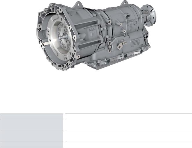
TGE Engine

In the MAN TGE, only 2.0-litre turbo diesel engines from the VWnutz modular diesel construction kit are used.
The use of a uniform engine geometry with many identical parts creates high synergy effects and reduces manufacturing and maintenance costs.
Transverse installation |
Longitudinal installation |
m002_002
The engines of the MAN TGE have been specially designed for commercial vehicles to meet the high requirements in terms of mileage, driving resistance, driving profi le and service life. Adjustments were made, for example, to the intercooling, the cylinder head, the intake manifold, the EGR cooler, the turbochargers and the oil pan. The installation position is adapted to the commercial vehicle design. Depending
on the drive concept used, the engines are installed transversely or longitudinally - an absolute special feature within a vehicle series. In addition, transversely installed engines are installed at an angle of 8° to the front in order to make optimum use of the available installation space. Longitudinally installed engines have a larger oil pan and an increased oil quantity. Engines with one or two turbochargers are used.
A total of up to four power stages are available, ranging from 75 kW to
130 kW. The after-treatment of the exhaust gases is carried out by an SCR system for nitrogen oxide reduction. Additional options, e. g. different generators and compressors, are possible with the accessory drive used.
2
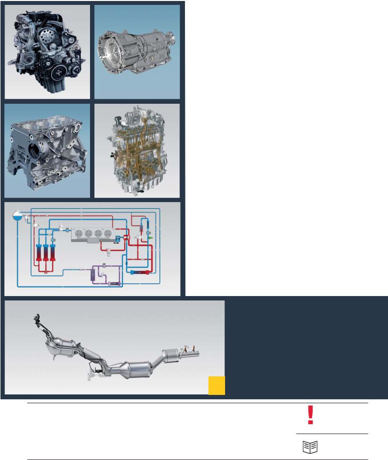
TABLE OF CONTENTS
|
|
|
|
|
4 |
INTRODUCTION |
|
|
|
|
|
10 |
GEARBOX |
|
|
|
|
|
14 |
ENGINE MECHANICS |
4 |
10 |
|||||
|
|
|
|
|
23 |
OIL SYSTEM |
|
|
|
|
|
26 |
COOLING SYSTEM |
|
|
|
|
|
33 |
ENGINE MANAGEMENT |
14 |
23 |
|||||
|
|
|
|
|
50 |
EXHAUST SYSTEM |
|
|
|
|
|
58 |
SERVICE |
|
|
|
|
|
||
|
26 |
|
|
|||
50
The MAN TGE Guide teaches the basics of design and function for sales and after-sales of new vehicle models, new
vehicle components or new technologies. Hint The MAN TGE Guide is not a sales manual nor a repair guide! Specifi ed values are for the sake of easy understanding
only and refer to the data status valid at the time the MAN TGE Guide was created. The contents are not updated.
Please use the appropriate technical literature for customer advice, maintenance and repair work.
Reference
3

INTRODUCTION
2.0l Turbo diesel - 75 kW - DAUB
Technical features
Transverse installation
Liquid-cooled intercooler
High pressure exhaust gas recirculation
Delphi Common Rail direct injection
Liquid-cooled injector for reduction agent
Injectors with solenoid valve
Single-piston high-pressure pump (mono turbocharger)
m002_009
Technical data |
|
|
|
Torque and power diagram |
|
|
|
|
|
Engine designation |
|
2.0 l Turbo diesel |
||
|
|
|
||
|
|
75 kW |
|
|
Engine identifi cation
Cubic capacity
Engine design
Valves per cylinder
Bore
Stroke
Compression ratio
Max. power at 1/min
Max. torque at 1/min
Engine management
Fuel
Charge
Exhaust gas recirculation
Exhaust emission standard1)
DAUB
1968 cm3
4-cylinder in-line engine
4
81.0 mm
95.5 mm
15.5: 1
75 kW
3250 – 3500
300 Nm
1400 – 2250
Delphi DCM6.2
DIN EN 590
Mono turbocharger
yes
EU6 plus
|
500 |
|
400 |
Torque [Nm] |
300 |
200 |
|
|
100 |
|
0 |
1000 |
2000 |
3000 |
4000 |
|
|
Torque [1/min] |
|
||
Torque |
|
|
|
Power |
|
|
|
||
100 |
|
80 |
Power[kW] |
40 |
|
60 |
|
20
0
1) EU6 plus: Light duty homologation <2840 kg reference weight (roller test bench)
4

2.0l Turbo diesel - 90 kW - DASA
Technical features
Longitudinal installation
Liquid-cooled intercooler
High pressure exhaust gas recirculation
Delphi Common Rail direct injection
Liquid-cooled injector for reduction agent
Injectors with solenoid valve
Single-piston high-pressure pump (mono turbocharger)
Technical data
Engine designation
Engine identifi cation
Cubic capacity
Engine design
Valves per cylinder
Bore
Stroke
Compression ratio
Max. power at 1/min
Max. torque at 1/min
Engine management
Fuel
Charge
Exhaust gas recirculation
Exhaust emission standard1)
2.0 l Turbo diesel
90 kW
DASA
1968 cm3
4-cylinder in-line engine
4
81.0 mm
95.5 mm
15.5: 1
90 kW
3250 – 3500
300 Nm
1400 – 2250
Delphi DCM6.2
DIN EN 590
Mono turbocharger
yes
EURO VI
m002_010
Torque and power diagram
|
500 |
|
100 |
|
|
|
|
||
Torque [Nm] |
400 |
|
80 |
Power [kW] |
|
||||
|
||||
300 |
|
60 |
||
|
||||
|
||||
200 |
|
40 |
||
|
||||
|
||||
|
100 |
|
20 |
|
|
|
|
||
|
|
|
||
|
0 |
|
|
|
|
|
0 |
|
|
|
|
|
||
1000 |
2000 |
3000 |
4000 |
||
|
|
Torque [1/min] |
|
||
|
|
|
|
|
|
|
Torque |
|
|
|
Power |
|
|
|
|
||
|
|
|
|
|
|
1) EURO VI: Heavy duty homologation >2380 kg reference weight (engine test bench)
5

2.0l Turbo diesel - 103 kW - DAUA / DASB
Technical features
DAUA - transverse installation
DASB - longitudinal installation
Liquid-cooled intercooler
High pressure exhaust gas recirculation
Delphi Common Rail direct injection
Liquid-cooled injector for reduction agent
Injectors with solenoid valve
Single-piston high-pressure pump (mono turbocharger)
m002_011
Technical data
Engine designation
Engine identifi cation
Cubic capacity
Engine design
Valves per cylinder
Bore
Stroke
Compression ratio
Max. power at 1/min
Max. torque at 1/min
Engine management
Fuel
Charge
Exhaust gas recirculation
Exhaust emission standard1)
2.0l Turbo diesel 103 kW
DAUA / DASB
1968 cm3
4-cylinder in-line engine
4
81.0 mm
95.5 mm
15.5: 1
103 kW
3500 – 3600
340 Nm
1600 – 2250
Delphi DCM6.2
DIN EN 590
Mono turbocharger
yes
EU6, EU6 plus
Torque and power diagram
|
500 |
125 |
|
|
400 |
100 |
|
Torque [Nm] |
300 |
75 |
Power [kW] |
200 |
50 |
||
|
100 |
25 |
|
|
0 |
0 |
|
1000 |
2000 |
3000 |
4000 |
||
|
|
Torque [1/min] |
|
||
|
|
|
|
|
|
|
Torque |
|
|
|
Power |
|
|
|
|
||
|
|
|
|
|
|
1) EU6 plus: Light duty homologation <2840 kg reference weight (roller test bench)
6

2.0l Turbo diesel - 130 kW - DAVA / DAWA
Technical features
DAVA - transverse installation
DAWA - longitudinal installation
Liquid-cooled intercooler
High pressure exhaust gas recirculation
Delphi Common Rail direct injection
Liquid-cooled injector for reduction agent
Injectors with solenoid valve
Double-piston high-pressure pump (bi-turbocharger)
m002_012
Technical data
Engine designation
Engine identifi cation
Cubic capacity
Engine design
Valves per cylinder
Bore
Stroke
Compression ratio
Max. power at 1/min
Max. torque at 1/min
Engine management
Fuel
Charge
Exhaust gas recirculation
Exhaust emission standard1)
2.0l Turbo diesel 130 kW
DAVA / DAWA
1968 cm3
4-cylinder in-line engine
4
81.0 mm
95.5 mm
15.5: 1
130 kW
3600
410 Nm
1500 – 2000
Delphi DCM6.2
DIN EN 590
Bi-turbocharger
yes
EU6, EU6 plus,
EURO V/VI
Torque and power diagram
|
500 |
150 |
|
|
400 |
120 |
|
Torque [Nm] |
300 |
90 |
Power [kW] |
200 |
60 |
||
|
100 |
30 |
|
|
0 |
0 |
|
1000 |
2000 |
3000 |
4000 |
||
|
|
Torque [1/min] |
|
||
|
|
|
|
|
|
|
Torque |
|
|
|
Power |
|
|
|
|
||
|
|
|
|
|
|
1)EU6 plus: Light duty homologation <2840 kg reference weight (roller test bench) EURO VI: Heavy duty homologation >2380 kg reference weight (engine test bench)
7
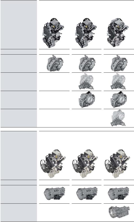
The engine-gearbox combinations
Transverse installation |
2.0 l Turbo diesel |
2.0 l Turbo diesel |
2.0 l Bi-turbo diesel |
|
75 kW |
103 kW |
130 kW |
|
DAUB |
DAUA |
DAVA |
6-speed manual gearbox
0AX front wheel drive
6-speed manual gearbox
0AX all-wheel drive
8-speed automatic gearbox
09Q front wheel drive
8-speed automatic gearbox 09Q all-wheel drive
Longitudinal installation 2.0 l Turbo diesel |
2.0 l Turbo diesel |
2.0 l Bi-turbo diesel |
90 kW |
103 kW |
130 kW |
DASA |
DASB |
DAWA |
6-speed manual gearbox
0F6 rear wheel drive
8-speed automatic gearbox
0DR rear-wheel drive
8

9
GEARBOX
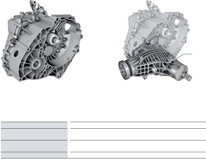
6-speed manual transmission 0AX - transverse installation
This transmission is used in front wheel drive or 4x4 four-wheel drive vehicles. For use in the MAN TGE, it was adapted with respect to gear ratios and
to the installation space-specifi c |
fl ange-mounted angle drive |
conditions. |
for 4x4 all-wheel drive. |
In the MAN TGE, it is used both for |
|
front wheel drive, and with a |
|
Front-wheel drive |
All-wheel drive 4x4 |
Angle drive
m002_080 |
m002_081 |
Developer/Manufacturer
Gearbox designation
Gearbox characteristics
Torque
Volkswagen AG
MQ500-6A/-6F
In service code: 0AX
6-speed manual transmission with four shafts and cable control for front-wheel or all-wheel drive in transverse installation
410 Nm
10
6-speed manual transmission 0F6 - longitudinal installation
The newly developed manual transmission is used in rear-wheel drive vehicles. For the MAN TGE it has been designed
with a correspondingly robust layout. This applies, for example, to the design of bearings and synchronization.
A gearbox-side power take-off is available as an option.
Developer/Manufacturer
Gearbox designation
Gearbox characteristics
Torque
m002_082 |
m002_083 |
Power take-off
ZF Friedrichshafen AG
ML410-6H
In service code: 0F6
2-shaft manual transmission with single and multiple synchronized speeds. The gearbox consists of a drive shaft in conjunction with a coaxial output shaft, a countershaft and a reverse shaft for reverse gear.
The power take-off is driven by the countershaft.
410 Nm
11
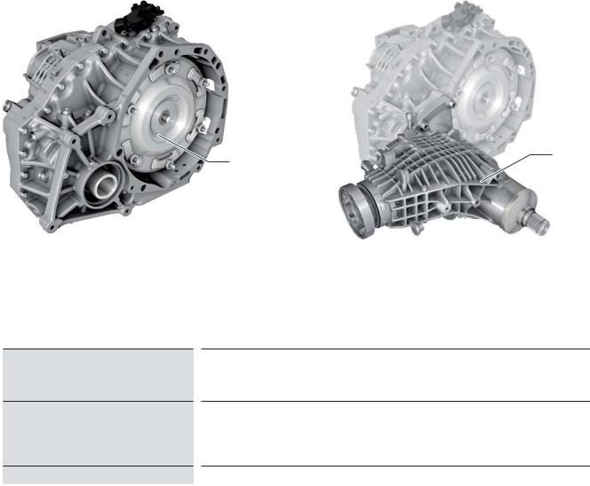
8-speed automatic transmission 09Q - transversal installation
The newly developed automatic transmission is used in front wheel drive or 4x4 four-wheel drive vehicles.
For use in the MAN TGE, care was taken to ensure a robust design of the converter, gearbox housing, differential
and parking lock. In all-wheel drive vehicles, the drive to the rear axle is provided by a fl ange-mounted angular drive.
Front-wheel drive |
All-wheel drive 4x4 |
Angle drive
Torque converters
m002_078 |
m002_079 |
Developer/Manufacturer |
|
AISIN AW CO., LTD Japan |
AQ450-8A/-8F
Gearbox designation
In service code: 09Q
Electro-hydraulically controlled 8-speed planetary gearbox
(stepped automatic transmission) with hydrodynamic torque converter and slip-
Gearbox characteristics
controlled torque converter lock-up clutch for front or all-wheel drive in transverse installation
Torque |
410 Nm |
12
8-speed automatic transmission 0DR - longitudinal installation
The newly developed automatic trans- |
designed with a correspondingly robust |
the planet set. In addition, the gearbox |
mission is used in rear-wheel drive |
layout. |
housing, lining plates, plate supports |
vehicles. For the MAN TGE it has been |
This concerns e. g. the transducer and |
and the parking lock are reinforced. |
Developer/Manufacturer
Gearbox designation
Gearbox characteristics
Torque
m002_084
ZF Friedrichshafen AG
AL550-8H
In service code: 0DR
Electro-hydraulically controlled 8-speed planetary gear with hydrodynamic torque converter with slip-controlled torque converter lock-up clutch
410 Nm
13

ENGINE MECHANICS
The cylinder block
The cylinder block of the EA288 engine is made of grey cast iron. This is an alloy of cast iron with lamellar graphite. The cylinder block has deep-seated screw threads for long cylinder head screws.
This achieves a good force fl ow distribu- |
The design of the cooling ducts in the |
tion in the structure of the cylinder block |
cylinder block ensures good cooling of |
as well as a balanced pressure distribu- |
the webs between the cylinders. |
tion over the entire circumference of the |
|
cylinder head gasket. |
|
m002_020
14

The crank drive
Crankshaft
Due to the high mechanical load, a forged crankshaft with fi ve bearings is used in the 2.0l TDI engine. Instead of the usual eight counterweights, this
crankshaft has four counterweights to compensate the rotating inertia forces. This reduces the load on the crankshaft
bearings. The toothed belt wheel for driving the oil pump is shrunk on the crankshaft.
Pistons and conrods
The pistons of the EA288 engine have no valve seat pockets. This design of the pistons reduces the dead space and improves the swirl formation of the
intake air in the cylinder. The pistons have an annular cooling channel into which oil is injected via piston nozzles
for cooling the piston ring zone. The connecting rods are designed as cracked tapered connecting rods.
m002_021
15

The cylinder head
The cylinder head is made of an alu- |
the outlet side. The valve is actuated by |
minium alloy. |
roller cam followers with compensating |
Four valves are installed per cylinder. |
elements. |
The valve arrangement is the classic |
The combustion chamber pressure |
design, i. e. the inlet valves are located |
transmitter for cylinder 3 G679 is inte- |
on the inlet side and the outlet valves on |
grated in the glow plug for this cylinder |
and screwed into the cylinder head like the other glow plugs. In order to increase service life, the head of the EA288Nutz has been improved in terms of thermal management compared to the basic engine.
 Cylinder head
Camshaft housing
m002_022
Camshaft housing
The camshafts are fi rmly and inseparably integrated into a closed bearing frame by means of a thermal joining process. This process enables a very rigid design of the camshaft bearings with low weight. In order to reduce friction, the fi rst bearing, most loaded by
the toothed belt drive, is a needle roller bearing. The encoder wheel for Hall sensor G40 ins located on the inlet camshaft. The signal from the Hall sensor enables the engine control unit to detect the current position of the camshafts.
Both camshafts are driven by only one drive wheel.
The intake camshaft is driven by a spur gearing from the exhaust camshaft. This design improves the service life of the timing belt.
Spur gearing
Needle roller bearing
|
|
|
Encoder wheel |
|
Bearing frame with |
|
|
|
|
||
Hall sensor G40 |
|
cam shafts |
|||
|
|
|
m002_023 |
|
|
16
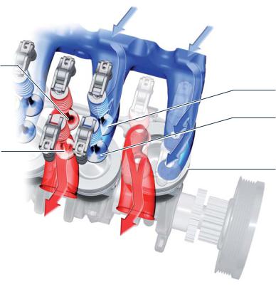
Valve arrangement
In order to meet future exhaust emission |
are arranged one after the other in fl ow |
standards, the valve arrangement is |
direction. |
rotated with respect to the longitudinal |
The camshafts thus operate one intake |
axis of the engine. As a result, the inlet |
and one exhaust valve per cylinder. The |
and outlet channels for each cylinder |
|
valve arrangement is designed in a way that the inlet and outlet ducts achieve a maximum fl ow rate with good swirl effect.
Intake air
First exhaust valve
Cylinder 2
First inlet valve
Cylinder 2
Second inlet valve
Cylinder 2
Second outlet valve Cylinder 2
Cylinder 1
Exhaust gas
m002_028
17

The crankcase ventilation
The components of the crankcase ventilation system are integrated into the cylinder head cover, in addition to the oil fi ller neck and the pressure accumulator for the engine's vacuum system. The air currents occurring in combustion engines between piston rings and cylinder walls, the so-called blow-by gases, are returned to the intake area
via the crankcase ventilation. This avoids environmental pollution caused by oil-containing gases. For effective oil separation, crankcase ventilation is performed in several stages. First of all, the blow-by gases from the crankshaft and camshaft space are transferred to a calming volume of the cylinder head cover.
There, the larger oil droplets settle on the walls and drip into the cylinder head. Subsequently, the oil-containing gases are separated off by a cyclone separator.
The purifi ed gases are fed to the suction pipe via the pressure control valve and are then lead to the combustion.
For countries with a cold climate, the crankcase ventilation is equipped with a heating resistor. The heating resistor prevents freezing of the line connection from the cylinder head cover to the intake manifold in case of low outside temperatures.
Heating resistor for crankcase ventilation
Pressure regulator
Vacuum tank
Fine oil separation (cyclones)
Calming volume
Oil return from
fi ne oil separator
Gravity valve
for oil return fl ow
m002_024
18
 Loading...