


 Loading...
Preface
This Repair Manual is designed to facilitate competent repair of the engines listed herein.
The pictures and relevant descriptions show typical work that may not always be applicable to the engine in hand, which nevertheless does not mean that they are not correct.
In such cases the repair work is to be planned and carried out in a similar way.
Please note that all jobs described in this Repair Manual were carried out on an engine which was not installed.
The expert knowledge necessary for handling Diesel engines was taken for granted when this publication was compiled.
Note:
Only use fuel, coolants and lubricants in accordance with MAN regulations, otherwise the manufacturer’s warranty will not apply!
For basic information on the fuels see the publication “Fuels, Lubricants and Coolants for MAN Diesel Engines”.
You can find the approved products on the Internet at:
−http://www.man-mn.com/ " Products & Solutions " E-Business−
Any repair of components such as injection pump, alternator etc. ought to be left to our or the manufacturer’s service department.
Yours faithfully,
MAN Nutzfahrzeuge Aktiengesellschaft
Nuremberg Works
We reserve the right to make technical modifications in the course of further development.
♥ 2004 MAN Nutzfahrzeuge Aktiengesellschaft
Reprinting, copying or translation, even in the form of excerpts, is forbidden without the written permission of MAN. MAN expressly reserves all rights in accordance with the law on copyright.
MTDB |
Technical status: 11.2004 |
51.99598−8157 |
1

Instructions
Important instructions which concern technical safety and protection of persons are emphasised as shown below.
Danger:
This refers to working and operating procedures which must be complied with in order to rule out the risk to persons.
Caution:
This refers to working and operating procedures which must be complied with in order to prevent damage to or destruction of material.
Note:
Explanations useful for understanding the working or operating procedure to be performed.
Fitting flat seals / gaskets
Flat seals / gaskets are often inserted with sealing agents or adhesives to make fitting them easier or to achieve better sealing. Flat seals may slip in operation due to the “sewing-machine” effect, in particular if they are used between parts with different rates of linear expansion under heat (e.g. aluminium and cast iron), and leaks may then occur.
Example:
the cap of the front crankshaft seal. If a sealing agent or an adhesive is used here the flat seal will move inwards in the course of time as a result of the different expansion rates of the materials. Oil will be lost, for which the shaft seal may be thought to be responsible.
Flat seals / gaskets can be fitted properly only if the following points are observed:
DUse only genuine MAN seals/gaskets.
DThe sealing faces must be undamaged and clean.
DDo not use any sealing agent or adhesive − as an aid to fitting the seals a little grease can be used if necessary so that the seal will stick to the part to be fitted.
DTighten bolts evenly to the specified torque.
2

Contents |
|
Engine type classification . . . . . . . . . . . . . . . . . . . . . . . . . . . . . . . . . . . . . . . . . . . . . . . . . . . . . . . . . . . . . . . . . . |
5 |
Safety instructions . . . . . . . . . . . . . . . . . . . . . . . . . . . . . . . . . . . . . . . . . . . . . . . . . . . . . . . . . . . . . . . . . . . . . . . . |
6 |
Troubleshooting table . . . . . . . . . . . . . . . . . . . . . . . . . . . . . . . . . . . . . . . . . . . . . . . . . . . . . . . . . . . . . . . . . . . . . |
12 |
General notes on engine overhaul . . . . . . . . . . . . . . . . . . . . . . . . . . . . . . . . . . . . . . . . . . . . . . . . . . . . . . . . . . |
15 |
Commissioning after engine overhaul . . . . . . . . . . . . . . . . . . . . . . . . . . . . . . . . . . . . . . . . . . . . . . . . . . . . . . . |
16 |
Engine views D 2842 LE 620 . . . . . . . . . . . . . . . . . . . . . . . . . . . . . . . . . . . . . . . . . . . . . . . . . . . . . . . . . . . . . . . |
18 |
Engine lubrication schedule . . . . . . . . . . . . . . . . . . . . . . . . . . . . . . . . . . . . . . . . . . . . . . . . . . . . . . . . . . . . . . . . |
20 |
Fuel diagram . . . . . . . . . . . . . . . . . . . . . . . . . . . . . . . . . . . . . . . . . . . . . . . . . . . . . . . . . . . . . . . . . . . . . . . . . . . . |
22 |
Schematic diagram of cooling system . . . . . . . . . . . . . . . . . . . . . . . . . . . . . . . . . . . . . . . . . . . . . . . . . . . . . . . |
23 |
Fuel system |
|
Check the base fitting of the high−pressure pump . . . . . . . . . . . . . . . . . . . . . . . . . . . . . . . . . . . . . . . . . . |
24 |
Removing and installing the high-pressure lines . . . . . . . . . . . . . . . . . . . . . . . . . . . . . . . . . . . . . . . . . . . . |
26 |
Removing and installing high-pressure pump . . . . . . . . . . . . . . . . . . . . . . . . . . . . . . . . . . . . . . . . . . . . . . |
27 |
Removing and installing the rail . . . . . . . . . . . . . . . . . . . . . . . . . . . . . . . . . . . . . . . . . . . . . . . . . . . . . . . . . . |
29 |
Removing and installing the rail pressure sensor, pressure relief valve . . . . . . . . . . . . . . . . . . . . . . . . |
31 |
Removing and installing the injectors . . . . . . . . . . . . . . . . . . . . . . . . . . . . . . . . . . . . . . . . . . . . . . . . . . . . . |
32 |
Fuel prefilter with water separator . . . . . . . . . . . . . . . . . . . . . . . . . . . . . . . . . . . . . . . . . . . . . . . . . . . . . . . . |
37 |
Fuel filter, exchanging filter cartridge . . . . . . . . . . . . . . . . . . . . . . . . . . . . . . . . . . . . . . . . . . . . . . . . . . . . . |
38 |
Flame-starter sheathed-element glow plug, removing and installing . . . . . . . . . . . . . . . . . . . . . . . . . . . |
39 |
Cooling system |
|
Draining and filling coolant . . . . . . . . . . . . . . . . . . . . . . . . . . . . . . . . . . . . . . . . . . . . . . . . . . . . . . . . . . . . . . |
40 |
Removing and installing thermostats . . . . . . . . . . . . . . . . . . . . . . . . . . . . . . . . . . . . . . . . . . . . . . . . . . . . . |
41 |
Removing and installing coolant pump . . . . . . . . . . . . . . . . . . . . . . . . . . . . . . . . . . . . . . . . . . . . . . . . . . . . |
42 |
Repairing coolant pump with high-temperature and low-temperature parts . . . . . . . . . . . . . . . . . . . . . |
44 |
Cleaning cooling system . . . . . . . . . . . . . . . . . . . . . . . . . . . . . . . . . . . . . . . . . . . . . . . . . . . . . . . . . . . . . . . . |
51 |
Lubrication |
|
Changing oil filter . . . . . . . . . . . . . . . . . . . . . . . . . . . . . . . . . . . . . . . . . . . . . . . . . . . . . . . . . . . . . . . . . . . . . . |
53 |
Removing and installing the oil cooler . . . . . . . . . . . . . . . . . . . . . . . . . . . . . . . . . . . . . . . . . . . . . . . . . . . . |
54 |
Removing and installing, repairing oil pump . . . . . . . . . . . . . . . . . . . . . . . . . . . . . . . . . . . . . . . . . . . . . . . |
55 |
Oil injection nozzle . . . . . . . . . . . . . . . . . . . . . . . . . . . . . . . . . . . . . . . . . . . . . . . . . . . . . . . . . . . . . . . . . . . . . |
59 |
Flywheel / Crankshaft seal |
|
Removing and fitting vibration damper, replacing front crankshaft gasket . . . . . . . . . . . . . . . . . . . . . . |
61 |
Removing and installing flywheel,replacing starter gear ring . . . . . . . . . . . . . . . . . . . . . . . . . . . . . . . . . |
65 |
Replacing crankshaft seal (flywheel end) . . . . . . . . . . . . . . . . . . . . . . . . . . . . . . . . . . . . . . . . . . . . . . . . . . |
67 |
Replacing the bearing race . . . . . . . . . . . . . . . . . . . . . . . . . . . . . . . . . . . . . . . . . . . . . . . . . . . . . . . . . . . . . . |
68 |
Crankshaft gaskets . . . . . . . . . . . . . . . . . . . . . . . . . . . . . . . . . . . . . . . . . . . . . . . . . . . . . . . . . . . . . . . . . . . . |
69 |
Intake / exhaust system |
|
Removing and installing intake manifold . . . . . . . . . . . . . . . . . . . . . . . . . . . . . . . . . . . . . . . . . . . . . . . . . . |
70 |
Removing and installing exhaust pipe . . . . . . . . . . . . . . . . . . . . . . . . . . . . . . . . . . . . . . . . . . . . . . . . . . . . |
71 |
Turbocharger, trouble shooting . . . . . . . . . . . . . . . . . . . . . . . . . . . . . . . . . . . . . . . . . . . . . . . . . . . . . . . . . . |
72 |
Checking the charge-air pressure . . . . . . . . . . . . . . . . . . . . . . . . . . . . . . . . . . . . . . . . . . . . . . . . . . . . . . . . |
74 |
Removing and installing turbocharger . . . . . . . . . . . . . . . . . . . . . . . . . . . . . . . . . . . . . . . . . . . . . . . . . . . . |
75 |
Checking axial and radial clearance of turbocharger rotor shaft . . . . . . . . . . . . . . . . . . . . . . . . . . . . . . |
77 |
Cylinder head |
|
Removing and installing the cylinder head . . . . . . . . . . . . . . . . . . . . . . . . . . . . . . . . . . . . . . . . . . . . . . . . . |
78 |
Setting the valve clearance . . . . . . . . . . . . . . . . . . . . . . . . . . . . . . . . . . . . . . . . . . . . . . . . . . . . . . . . . . . . . |
82 |
Dismantling and assembling the rocker arm mechanism . . . . . . . . . . . . . . . . . . . . . . . . . . . . . . . . . . . . |
83 |
Removing and installing valves . . . . . . . . . . . . . . . . . . . . . . . . . . . . . . . . . . . . . . . . . . . . . . . . . . . . . . . . . . |
87 |
Removing and installing valve guides . . . . . . . . . . . . . . . . . . . . . . . . . . . . . . . . . . . . . . . . . . . . . . . . . . . . . |
93 |
Replacing valve seat insert . . . . . . . . . . . . . . . . . . . . . . . . . . . . . . . . . . . . . . . . . . . . . . . . . . . . . . . . . . . . . |
94 |
Reworking valve seat . . . . . . . . . . . . . . . . . . . . . . . . . . . . . . . . . . . . . . . . . . . . . . . . . . . . . . . . . . . . . . . . . . |
96 |
Refacing valves . . . . . . . . . . . . . . . . . . . . . . . . . . . . . . . . . . . . . . . . . . . . . . . . . . . . . . . . . . . . . . . . . . . . . . . |
99 |
3

Contents |
|
Valve timing |
|
Removing and installing the gear case . . . . . . . . . . . . . . . . . . . . . . . . . . . . . . . . . . . . . . . . . . . . . . . . . . . . |
100 |
Removing and installing camshaft . . . . . . . . . . . . . . . . . . . . . . . . . . . . . . . . . . . . . . . . . . . . . . . . . . . . . . . . |
102 |
Removing and fitting camshaft bearing bushes . . . . . . . . . . . . . . . . . . . . . . . . . . . . . . . . . . . . . . . . . . . . |
105 |
Checking the valve timing . . . . . . . . . . . . . . . . . . . . . . . . . . . . . . . . . . . . . . . . . . . . . . . . . . . . . . . . . . . . . . . |
114 |
Crankgear, pistons |
|
Removing and installing crankshaft . . . . . . . . . . . . . . . . . . . . . . . . . . . . . . . . . . . . . . . . . . . . . . . . . . . . . . |
115 |
Removing and installing pistons with conrods . . . . . . . . . . . . . . . . . . . . . . . . . . . . . . . . . . . . . . . . . . . . . . |
118 |
Removing pistons from conrod and fitting, checking − replacing conrod . . . . . . . . . . . . . . . . . . . . . . . |
121 |
Removing and installing piston rings . . . . . . . . . . . . . . . . . . . . . . . . . . . . . . . . . . . . . . . . . . . . . . . . . . . . . |
123 |
Replacing cylinder liners . . . . . . . . . . . . . . . . . . . . . . . . . . . . . . . . . . . . . . . . . . . . . . . . . . . . . . . . . . . . . . . . |
125 |
Measuring piston protrusion . . . . . . . . . . . . . . . . . . . . . . . . . . . . . . . . . . . . . . . . . . . . . . . . . . . . . . . . . . . . . |
129 |
Attachments |
|
Removing and installing starter motor . . . . . . . . . . . . . . . . . . . . . . . . . . . . . . . . . . . . . . . . . . . . . . . . . . . . |
130 |
V−belts . . . . . . . . . . . . . . . . . . . . . . . . . . . . . . . . . . . . . . . . . . . . . . . . . . . . . . . . . . . . . . . . . . . . . . . . . . . . . . . |
131 |
Tensioning and changing V−belt . . . . . . . . . . . . . . . . . . . . . . . . . . . . . . . . . . . . . . . . . . . . . . . . . . . . . . . . . |
132 |
Removing and installing speed pickup . . . . . . . . . . . . . . . . . . . . . . . . . . . . . . . . . . . . . . . . . . . . . . . . . . . . |
133 |
Service Data |
|
Specifications . . . . . . . . . . . . . . . . . . . . . . . . . . . . . . . . . . . . . . . . . . . . . . . . . . . . . . . . . . . . . . . . . . . . . . . . . |
136 |
Crankcase . . . . . . . . . . . . . . . . . . . . . . . . . . . . . . . . . . . . . . . . . . . . . . . . . . . . . . . . . . . . . . . . . . . . . . . . . . . . |
137 |
Cylinder liner . . . . . . . . . . . . . . . . . . . . . . . . . . . . . . . . . . . . . . . . . . . . . . . . . . . . . . . . . . . . . . . . . . . . . . . . . . |
137 |
Crankshaft . . . . . . . . . . . . . . . . . . . . . . . . . . . . . . . . . . . . . . . . . . . . . . . . . . . . . . . . . . . . . . . . . . . . . . . . . . . . |
138 |
Flywheel and starter gear ring . . . . . . . . . . . . . . . . . . . . . . . . . . . . . . . . . . . . . . . . . . . . . . . . . . . . . . . . . . . |
141 |
Conrods . . . . . . . . . . . . . . . . . . . . . . . . . . . . . . . . . . . . . . . . . . . . . . . . . . . . . . . . . . . . . . . . . . . . . . . . . . . . . . |
142 |
Pistons . . . . . . . . . . . . . . . . . . . . . . . . . . . . . . . . . . . . . . . . . . . . . . . . . . . . . . . . . . . . . . . . . . . . . . . . . . . . . . . |
143 |
Cylinder head . . . . . . . . . . . . . . . . . . . . . . . . . . . . . . . . . . . . . . . . . . . . . . . . . . . . . . . . . . . . . . . . . . . . . . . . . |
144 |
Valve gear . . . . . . . . . . . . . . . . . . . . . . . . . . . . . . . . . . . . . . . . . . . . . . . . . . . . . . . . . . . . . . . . . . . . . . . . . . . . |
146 |
Engine lubrication D 2842 LE 620 . . . . . . . . . . . . . . . . . . . . . . . . . . . . . . . . . . . . . . . . . . . . . . . . . . . . . . . . |
149 |
Cooling system . . . . . . . . . . . . . . . . . . . . . . . . . . . . . . . . . . . . . . . . . . . . . . . . . . . . . . . . . . . . . . . . . . . . . . . . |
151 |
Repairing coolant pump with high−temperatureand low−temperature parts . . . . . . . . . . . . . . . . . . . . |
151 |
Turbocharger . . . . . . . . . . . . . . . . . . . . . . . . . . . . . . . . . . . . . . . . . . . . . . . . . . . . . . . . . . . . . . . . . . . . . . . . . |
152 |
Fuel system . . . . . . . . . . . . . . . . . . . . . . . . . . . . . . . . . . . . . . . . . . . . . . . . . . . . . . . . . . . . . . . . . . . . . . . . . . |
153 |
Starter motor . . . . . . . . . . . . . . . . . . . . . . . . . . . . . . . . . . . . . . . . . . . . . . . . . . . . . . . . . . . . . . . . . . . . . . . . . . |
154 |
Torque guide values . . . . . . . . . . . . . . . . . . . . . . . . . . . . . . . . . . . . . . . . . . . . . . . . . . . . . . . . . . . . . . . . . . . |
155 |
Special tools . . . . . . . . . . . . . . . . . . . . . . . . . . . . . . . . . . . . . . . . . . . . . . . . . . . . . . . . . . . . . . . . . . . . . . . . . . . . |
161 |
Index . . . . . . . . . . . . . . . . . . . . . . . . . . . . . . . . . . . . . . . . . . . . . . . . . . . . . . . . . . . . . . . . . . . . . . . . . . . . . . . . . . . |
174 |
4

All the engines dealt with here are related in terms of their design and make up a family.
The type classification, which is made up of a series of letters and numbers, reveals some of the features of the engine in question provided the reader is familiar with the underlying nomenclature.
The system is explained below using the model type D 2842 LE 620 as an example:
D |
The “D” at the start of the type classification stands for “Diesel” |
28 |
The numbers “28” indicates that the power plant in question has a bore of 128 mm |
4 |
The “4” means 142 mm stroke |
2 |
The “2” indicates that there are 12 cylinders. If there is a “0”, this is a 10−cylinder engine |
L |
This letter stands for “charge−air cooling” (German: Ladeluftkühlung) |
EThe “E” stands for “fitted engine” (German: Einbaumotor) and is intended to distinguish MAN vehicle engines
620 This is a factory-internal development number
5
Safety instructions
General information
This brief overview summarises important instructions and is structured into areas of main concern in order to impart the knowledge necessary to prevent accidents involving injury to persons, damage to the engine or other property and harm to the environment. Additional notes are included in the operator’s manual for the engine.
Important:
If despite all safety precautions an accident occurs as a result of contact with caustic acids, penetration of fuel into the skin, scalding with hot oil, anti-freeze splashes into the eyes etc, consult a doctor immediatel.
1. Instructions for preventing accidents with injury to persons
Checks, setting jobs and repair work must be carried out by authorised skilled personnel only.
DWhen carrying out maintenance and repair work, ensure that the engine cannot be accidentally started from the bridge by unauthorised persons.
DThe engine must be started and operated by authorised personnel only.
DWhen the engine is running, do not get too close to revolving components. Wear tight-fitting working clothes.
DDo not touch hot engine with bare hands: risk of burning yourself.
DKeep engine vicinity, ladder and steps free of oil and grease. Accidents resulting from slipping may have serious consequences.
DWork only with tools that are in good condition. Worn spanners slip: risk of injuries.
DPersons must not stand under an engine suspended from a crane hook. Keep lifting gear in good order.
DOpen coolant circuit only after the engine has cooled down. If opening the coolant circuit while the engine is hot is unavoidable, observe the instructions in the chapter “Maintenance and care” in the Operator’s Manual.
DNeither retighten nor open pressurised pipelines and hoses (lube oil circuit, coolant
circuit and downstream hydraulic oil circuit if fitted): risk of injuries resulting from emerging fluids.
DWhen checking the injection nozzles, do not hold your hands in the fuel jet. Do not inhale fuel mist.
6

Safety instructions
DWhen working on the electrical system, unplug earth cable from battery first and reconnect it last to avoid short-circuits.
DObserve the manufacturer’s instructions for handling batteries.
Caution:
Battery acid is toxic and caustic. Battery gases are explosive.
DWhen carrying out welding work, observe the “Information sheets for welders”.
2.Instructions for preventing damage to the engine and premature wear
DPrior to repairing the engine, clean it thoroughly. Ensure that dirt, sand or foreign matter will not get into the engine during repair work.
DIn the event of operational faults immediately identy the cause and rectify to prevent more serious damage.
DAlways use genuine MAN parts only. Installation of “equally” good parts from other suppliers may cause severe damage for which the workshop carrying out the work is responsible.
DNever operate the engine while it is dry, i.e. without lubricant or coolant.
Use a suitable label to mark engines not ready for operation.
DOnly use operating materials (fuel, engine oil, antifreeze and anticorrosion agents) approved by MAN. Ensure that everything is kept clean. Diesel fuel must be free of water.
DDo not fill up with engine oil above the max. notch on the dipstick. Do not exceed the engine’s maximum permissible operating inclination.
Non-compliance with these instructions may cause severe engine damage.
DControl and monitoring devices (charge check, oil pressure, coolant temperature) must work faultlessly.
DObserve the instructions for operating the alternator; see chapter “Maintenance and care” in the Operator’s Manual.
7

Safety instructions
3. Instructions for preventing environmental damage
Engine oil and filter cartridges and elements, fuel / fuel filters
DTake old oil to an old oil disposal point only.
DEnsure without fail that oil and Diesel fuel will not get into the sewerage system or the ground.
Caution:
Danger of contaminating potable water!
DTreat filter elements and cartridges as special waste.
Coolant
DTreat undiluted anticorrosion and / or antifreeze agents as special waste.
DThe regulations of the relevant local authorities are to be observed for the disposal of spent coolants.
4. Instructions for handling used engine oil *
Prolonged or repeated contact of any kind of engine oil with the skin causes the skin to degrease, which may result in dryness, irritation or inflammation. Old engine oil also contains hazardous substances which in animal experiments have caused skin cancer. Handling old engine oil does not pose any health hazard if the basic safety and hygiene related regulations are observed.
Health and safety regulations:
DAvoid prolonged, excessive or repeated contact of old engine oil with the skin.
DUse a suitable skin protection agent or wear protective gloves.
DClean the skin that has been in contact with engine oil.
−Wash yourself thoroughly with soap and water. A nailbrush is an effective aid.
−Special hand cleaning agents facilitate cleaning soiled hands.
−Do not use petrol, Diesel fuel, gas oil, fluxes or solvents as cleaning agents.
DAfter washing apply moisturising handcream to your skin.
DChange oil-soaked clothes and shoes.
DDo not put any oil-soaked cloths into pockets.
Pay meticulous attention to the proper disposal of old engine oil. − Old oil is a water hazard −
Therefore, do not pour any old oil into the ground, the drains or the sewerage system. Any violation of this rule is punishable.
Collect and dispose of old engine oil properly. For information concerning collection points, contact seller, supplier or the local authorities.
Based on the “Information sheed for handling used engine oil” (Notes on how to handle old engine oil).
8
Safety regulations
5. Special instructions when working on the common rail system
Accident protection
DRisk of injury!
Fuel jets can cut through skin.
The atomisation of fuel creates a fire risk.
−When the engine is running never loosen the screw connections on the fuel’s highpressure side of the common rail system (injection line from the high-pressure pump to the rail, on the rail and on the cylinder head to the injector)
−Keep away from the engine when it is running
DRisk of injury!
When the engine is running the lines are constantly under a fuel pressure of up to 1600 bar.
−Wait at least a minute until the pressure in the rail has dropped before loosening a screw connection
−If necessary check the pressure drop in the rail with MAN-Cats
DRisk of injury!
−People with pacemaker must keep at least 20 cm away from the running engine
−Do not touch live parts on the electric connection of the injectors when the engine is running
9

Safety regulations
Cleanliness
Today modern components of diesel injection consist of high-precision parts which are exposed to extreme stresses. The high-precision technology requires the utmost cleanliness during all work on the fuel system.
Even a particle of dirt over 0.2 mm can lead to the failure of components.
The measures described as follows are therefore essential before work begins:
Risk of damage from penetration of dirt!
D Before working on the clean side of the fuel system clean the engine and the engine compartment (high-pressure cleaner). During cleaning the fuel system must be closed
DCarry out visual inspection for any leakage or damage to the fuel system
DDo not spray the high-pressure cleaner direct onto the electric components, or alternatively keep them covered
DDo not carry out any welding or sanding work in the engine compartment during maintenance / repair
DAvoid air movements (any swirling of dust when starting engines)
DThe area of the still closed fuel system must be cleaned and dried with the aid of compressed air
DRemove detached particles of dirt such as paint chippings and insulation material with a suitable extractor (industrial type vacuum cleaner)
DCover areas of the engine compartment from which dust particles could be detached with clean foil
DWash your hands and put on clean work clothes before starting the disassembly work
DClean tools and working materials before starting to work
10

Safety regulations
When carrying out the work it is essential to comply with the following measures:
Risk of damage from penetration of dirt!
DWhen the clean side of the fuel system has been opened it is not permissible to use compressed air for cleaning
DDuring assembly work loose dirt must be removed with the aid of suitable extractors (industrial type vacuum cleaners)
DUse only fluff-free cleaning cloths on the fuel system
DOnly tools without any damage may be used (cracked chrome coatings)
DWhen removing and installing components do not use materials such as cloths, cardboard or wood since these could shed particles and fine fibres
DIf any paint chips / flakes off when connections are loosened (from possible over-coa- ting) these chippings must be carefully removed before finally loosening the screw connection
DThe connection openings of all removed parts on the clean side of the fuel system are to be closed immediately with suitable caps (see special tools, page 172)
DThese caps / stoppers must be packed protected from dust prior to use and after being used once they must be disposed of
DFollowing this all the components must be carefully stored in a clean, closed container
DNever use used cleaning or testing liquids for these components
DNew parts must not be removed from their original packing material until directly before use
DWork on removed components may be carried out only at a workplace specially equipped for it
DIf removed parts are shipped always use the original packing material of the new part
11

Troubleshooting table
Faults and possible causes
We recommend
Repair work is to be considered complete only after the damage which has occurred and the possible causes have been eliminated. Ascertaining the causes of damage is frequently more difficult than eliminating the damage caused. For this reason we recommend you have the operational fault exactly described to you before removal or disassembly work is commenced. Then, track down the probable causes by asking specific questions, examining and eliminating these causes one by one with the aid of the table and your own experience. This helps to reduce repairs to those necessary and counter complaints about “premature” exchange of parts and expensive working and downtimes.
Remark:
The subsequent list is meant to be a memory aid so that no causes of damage will be overlooked in the elimination of faults. The precondition for this, however, is that you are familiar with the Repair Manual for the engine and the relevant Operator’s Manual as well as the publication “Fuels, Lubricants, Coolants for MAN Diesel Engines”.
12

Fault table
1.EDC self-diagnosis
2.Starter motor turns over engine slowly or not at all
3.Starter motor turns, engine fails to start, engine fails to start / difficult to start when cold
4.Engine stalls (dies) during operation, no longer starts (starter motor turns), engine fails to start / difficult to start when hot
5. Sudden, temporary engine shutdown, engine does not reach full revs 6. Engine runs at idle speed only, no throttle response
7. Engine runs at increased idle speed only, no throttle response 8. Rated engine speed significantly reduced (even at no load)
9. Reduced power output in all ranges
10. Irregular engine operation, loss of traction
11. Unstable idle speed, engine surges, misfiring, engine knocking
12. Engine judder
13. Unusual combustion noises
14. Excessive smoke emission: white smoke / blue smoke
15.Excessive smoke emission: black smoke
16.Engine temperature too high (coolant loss)
17. Fuel consumption too high
18.Lubrication oil pressure too low
19.Lube oil pressure too high
20. Lube oil consumption too high
21.Engine too “loud” / mechanical noises
22.Idle speed cannot be adjusted with idle speed operating unit
|
|
|
|
|
|
|
|
|
|
|
|
|
|
|
|
|
|
|
|
|
Possible causes |
x |
x |
|
|
|
|
|
|
|
|
|
|
|
|
|
|
|
|
|
|
|
Battery flat, battery lead connections loose or corroded, break in power circuit |
x |
|
|
|
|
|
|
|
|
|
|
|
|
|
|
|
|
|
|
|
|
Crankshaft drive blocked |
x |
x |
|
|
|
|
|
|
|
|
|
|
|
|
|
|
|
|
|
|
|
Starter solenoid switch sticks (clicks) / damaged, cable connection loose or dam- |
|
|
|
|
|
|
|
|
|
|
|
|
|
|
|
|
|
|
|
|
|
aged |
x |
x |
|
|
|
|
|
|
|
|
|
|
|
|
|
|
|
|
|
|
|
Starter motor / starter interlock relay defective (carbon brushes worked loose / |
|
|
|
|
|
|
|
|
|
|
|
|
|
|
|
|
|
|
|
|
|
worn, winding damaged, short to ground) |
x |
|
|
|
|
|
|
|
|
|
|
|
|
|
|
|
x |
x |
x |
|
|
Engine oil viscosity unsuitable, not suitable for ambient temperature, lube oil qual- |
|
|
|
|
|
|
|
|
|
|
|
|
|
|
|
|
|
|
|
|
|
ity does not comply with specifications |
|
|
|
|
|
|
|
|
|
|
|
|
|
|
|
|
|
|
|
|
|
|
|
|
|
|
|
|
|
x |
|
|
|
|
|
|
|
|
|
|
x |
|
|
Oil level in oil pan too high |
|
|
|
|
|
|
|
|
|
|
|
|
|
|
|
|
x |
|
|
|
|
Oil level in pan too low, oil in oil pan too thin (mixed with condensate or fuel) |
|
|
|
|
|
|
|
|
|
|
|
|
|
|
|
|
x |
|
|
|
|
Engine temperature too high |
|
|
|
|
|
|
|
|
|
|
|
|
|
|
|
|
|
|
|
|
|
|
|
|
|
|
|
|
|
|
|
|
|
|
|
|
|
|
x |
|
|
|
|
Oil filter clogged |
|
|
|
|
|
|
|
|
|
|
|
|
|
|
|
|
x |
x |
|
|
|
Oil pressure gauge defective |
|
|
|
|
|
|
|
|
|
|
|
|
|
|
|
|
x |
|
|
|
|
Safety valve in the oil circuit defective (does not close, spring fatigued or broken) |
|
|
|
|
|
|
|
|
|
|
|
|
|
|
|
|
x |
|
|
x |
|
Heavy bearing wear |
|
|
|
|
|
|
|
|
|
|
|
|
|
|
|
|
x |
|
|
|
|
Oil pump gears heavily worn |
|
|
|
|
|
|
|
|
|
|
|
|
|
|
|
|
|
|
|
x |
|
Timing gears worn, tooth flank backlash too great |
|
|
|
|
|
|
|
|
|
x |
|
|
x |
|
|
|
|
x |
|
|
|
Engine cold |
|
|
|
|
|
|
|
|
|
|
|
|
x |
|
|
|
|
|
|
|
|
Lube oil entering combustion chamber (piston rings worn, piston rings broken) − |
|
|
|
|
|
|
|
|
|
|
|
|
|
|
|
|
|
|
|
|
|
valve stem guide worn − overpressure in crankcase (crankcase breather |
|
|
|
|
|
|
|
|
|
|
|
|
|
|
|
|
|
|
|
|
|
clogged) |
|
|
|
|
|
|
|
|
|
|
|
|
|
|
|
|
|
x |
|
|
|
Safety valve in oil circuit defective (does not open), oil lines / oil galleries clogged |
|
|
|
|
|
|
|
|
|
|
|
|
|
|
|
|
|
|
x |
|
|
Leaks in lube oil circuit, particularly at turbocharger and oil cooler |
|
|
|
|
|
|
|
|
|
x |
|
|
|
|
|
|
|
|
x |
|
|
Piston rings heavily worn, broken |
|
|
|
|
|
|
|
|
|
x |
|
|
|
|
|
|
|
|
|
x |
|
Piston pins or crankshaft bearings loose |
|
|
|
|
|
|
|
|
|
|
|
|
|
|
|
|
|
|
|
|
|
|
|
|
|
|
|
|
|
|
|
|
|
|
|
|
|
|
|
|
x |
|
|
Valve stems heavily worn, bent |
|
x |
|
|
|
|
|
|
|
x |
|
|
|
|
|
|
|
|
|
x |
|
Valve clearance not correct |
|
x |
|
|
|
|
|
|
|
x |
|
|
|
|
|
|
|
|
|
|
|
Valves jammed |
|
x |
x |
|
|
|
|
x |
|
x |
|
|
|
|
|
|
|
|
|
|
|
Compression deficient, or more than 3−4 bar pressure difference between individ- |
|
|
|
|
|
|
|
|
|
|
|
|
|
|
|
|
|
|
|
|
|
ual cylinders |
|
x |
|
|
|
|
|
|
|
x |
|
|
|
|
|
x |
|
|
|
|
|
Valve seats leaking |
o |
|
|
x |
|
|
|
|
|
|
|
|
|
|
|
x |
|
|
|
|
|
Increased power input due to defective secondary loads / consumers such as |
|
|
|
|
|
|
|
|
|
|
|
|
|
|
|
|
|
|
|
|
|
hydraulic pumps, fan etc., power take-off engaged |
|
|
|
|
|
|
|
|
|
|
|
|
|
|
|
|
|
|
|
|
|
|
|
|
|
x |
|
|
|
x |
|
|
|
|
|
x |
|
x |
|
|
|
x |
|
Air filter fouled or clogged, charge air system leaking, air intake / exhaust lines |
|
|
|
|
|
|
|
|
|
|
|
|
|
|
|
|
|
|
|
|
|
clogged / leaking |
|
x |
x |
x |
x |
|
|
x |
x |
|
x |
|
x |
|
|
x |
|
|
|
|
|
Fuel low pressure system: fuel tank, prefilter, water trap faulty / clogged / mould / |
|
|
|
|
|
|
|
|
|
|
|
|
|
|
|
|
|
|
|
|
|
fungal attack, fuel unsuitable / contaminated (paraffin added) |
|
x |
x |
x |
|
|
|
x |
x |
x |
|
|
x |
|
|
x |
|
|
|
|
|
Fuel low pressure system: fuel lines leaking, broken, clogged |
13

Fault table
1.EDC self-diagnosis
2.Starter motor turns over engine slowly or not at all
3.Starter motor turns, engine fails to start, engine fails to start / difficult to start when cold
4.Engine stalls (dies) during operation, no longer starts (starter motor turns), engine fails to start / difficult to start when hot
5.Sudden, temporary engine shutdown, engine does not reach full revs
6.Engine runs at idle speed only, no throttle response
7.Engine runs at increased idle speed only, no throttle response 8. Rated engine speed significantly reduced (even at no load)
 9. Reduced power output in all ranges
10.Irregular engine operation, loss of traction
11.Unstable idle speed, engine surges, misfiring, engine knocking
12.Engine judder
13.Unusual combustion noises
14.Excessive smoke emission: white smoke / blue smoke
15.Excessive smoke emission: black smoke
16.Engine temperature too high (coolant loss)
17.Fuel consumption too high
18.Lubrication oil pressure too low
19.Lube oil pressure too high
20.Lube oil consumption too high
21. Engine too “loud” / mechanical noises
|
|
|
|
|
|
|
|
|
|
|
|
|
|
|
|
|
|
|
|
|
22. Idle speed cannot be adjusted with idle speed operating unit |
|
|
|
|
|
|
|
|
|
|
|
|
|
|
|
|
|
|
|
|
|
|
|
Possible causes |
|
|
x |
x |
x |
|
|
|
x |
x |
|
x |
|
x |
|
|
|
|
|
|
|
|
Fuel low pressure system: air in system (turn on ignition when bleeding system) |
|
|
|
|
|
|
|
|
|
|
|
|
|
|
|
|
|
|
|
|
|
|
|
|
|
x |
x |
x |
|
|
|
x |
x |
x |
x |
|
x |
|
|
x |
|
|
|
|
|
Fuel low pressure system: feed pump, main filter |
|
|
x |
|
|
|
|
|
x |
|
x |
x |
x |
o |
x |
|
x |
|
|
|
|
|
Fuel high pressure system: injectors defective / clogged / leaking / coked |
|
|
|
|
|
|
|
|
x |
|
x |
x |
x |
|
|
|
o |
|
|
|
|
|
Fuel high pressure system: pressure lines − constriction, cavitation, leaking |
|
|
|
x |
|
|
|
|
x |
|
o |
x |
x |
x |
x |
|
o |
|
|
|
|
|
Fuel high pressure system: high-pressure pump worn |
x |
|
|
|
|
x |
|
x |
x |
x |
o |
|
|
|
|
|
|
|
|
|
|
|
Pedal value sensor (driving lever signal) defective: connection lines, short circuit, |
|
|
|
|
|
|
|
|
|
|
|
|
|
|
|
|
|
|
|
|
|
|
interruption |
x |
|
|
|
|
|
|
x |
|
|
|
|
|
|
|
|
|
|
|
|
|
|
EDC rpm sensor defective, lead defective |
|
|
|
|
|
|
|
x |
|
|
x |
o |
|
|
|
|
|
|
|
|
|
|
EDC rpm sensor, polarity reversed |
x |
|
x |
x |
x |
o |
|
|
|
o |
o |
|
|
|
|
o |
|
|
|
|
|
|
EDC detects incorrect engine speed (interference signal on rpm sensor lead) |
x |
|
|
|
|
|
|
|
x |
|
|
|
|
|
x |
|
|
|
|
|
|
|
EDC boost pressure sensor: faulty, incorrect, implausible with atmospheric pres- |
|
|
|
|
|
|
|
|
|
|
|
|
|
|
|
|
|
|
|
|
|
|
sure sensor, line fault |
|
|
|
|
|
|
|
|
x |
|
x |
|
|
o |
x |
|
|
|
|
|
|
|
Exhaust turbocharger leaking or defective |
|
|
|
|
|
|
|
|
|
|
|
|
|
|
|
|
|
|
|
|
x |
|
Turbine and compressor wheel in the turbocharger soiled (running off balance) |
|
|
|
|
|
|
|
|
|
|
|
|
|
|
x |
|
|
|
|
|
|
|
Intercooler leaking, defective |
x |
|
o |
|
|
|
|
|
x |
x |
|
|
|
o |
|
x |
|
|
|
|
|
|
EDC coolant temperature sensor: faulty, line fault |
x |
|
|
|
|
|
|
|
x |
x |
|
|
|
|
|
|
|
|
|
|
|
|
EDC charge-air temperature sensor: faulty, line fault |
o |
|
|
|
|
|
|
|
x |
|
|
|
|
|
|
x |
|
|
|
|
|
|
Radiator fouled or failure of cooling system (temperatures too high) |
|
|
|
|
|
|
|
|
|
|
|
|
|
|
|
x |
|
|
|
|
|
|
Coolant level too low, air in the coolant circuit |
|
|
|
|
|
|
|
|
|
|
|
|
|
|
|
x |
|
|
|
|
|
|
V-belt for coolant pump drive not tensioned correctly |
|
|
|
|
|
|
|
|
|
|
|
|
|
|
|
x |
|
|
|
|
x |
|
Incorrect V-belt tension |
|
|
|
|
|
|
|
|
|
|
|
|
|
|
|
x |
|
|
|
|
|
|
Coolant pump leaking, defective / thermostat defective, does not open |
|
|
|
|
|
|
|
|
|
|
|
|
|
|
|
x |
|
|
|
|
|
|
Coolant lines leaking, blocked or twisted |
|
|
|
|
|
|
|
|
|
|
|
|
|
x |
|
|
|
|
|
|
|
|
Coolant entering combustion chamber (cylinder head / gasket leaking) |
x |
|
x |
x |
o |
|
|
|
|
o |
|
|
|
|
|
|
|
|
|
|
|
|
Power supply to EDC control unit interrupted or battery voltage too low |
x |
|
o |
o |
o |
|
|
|
|
|
|
|
|
|
|
|
|
|
|
|
|
|
EDC control unit defective (internal fault) |
|
x |
|
|
|
|
|
|
|
|
|
|
|
|
|
|
|
|
|
|
|
|
Incorrect EDC control unit (check MAN part number) |
x |
|
|
|
|
|
|
|
|
|
|
|
|
|
|
|
|
|
|
|
|
|
Afterrunning not completed |
|
|
|
|
|
|
|
|
x |
|
|
|
|
|
x |
|
|
|
|
|
|
|
Thermostat defective |
|
|
|
|
|
|
|
|
|
|
|
x |
|
|
|
|
|
|
|
|
|
|
Engine bearings worn |
14

General notes on engine overhaul
The service life of an engine is influenced by very different factors. It is therefore not possible to specify certain fixed numbers of operating hours for general overhauls.
In our view, it is not necessary to open up and engine or perform a general overhaul
as long as the engine has good compression values and the following operating values have not changed significantly in relation to the values measured on commissioning the engine:
DCharging pressure
DExhaust temperature
DCoolant and lubricant temperature
DOil pressure and oil consumption
DSmoke emissions
The following criteria greatly influence the length of the engine service life:
DCorrect power output setting according to the type of application
DTechnically correct installation
DInspection if installation by authorised personnel
DRegular maintenance as per maintenance plan
DChoice and quality of lube oil, fuel and coolant in accordance with the publication “Fuels, Lubricants and Coolants for MAN Diesel Engines”
15

Commissioning after engine overhaul
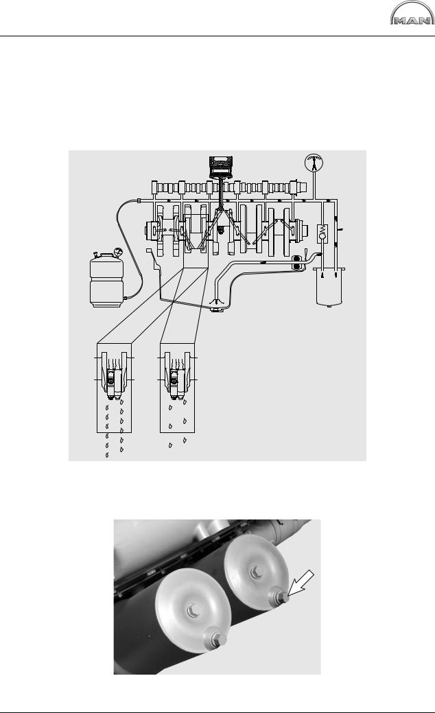
Pressurisation
It is extremely important for internal combustion engines (following the completion of repair work, i.e. in their dry state) to be pressurised with lube oil before being recommissioned. This procedure can also be used for ascertaining damage and its causes.
If engines are not pressurised, the risk of premature damage to bearing surfaces is very high because it takes a relatively long period of time for the lube oil drawn in from the oil pan via the oil pump to reach the individual bearings.
Such incipient damage need not necessarily lead to immediate bearing failure, but may impair the proper functioning of the bearings and reduce their service lives.
Diagram of the oil flow with unpressurised engines
16
Commissioning after engine overhaul
Pressurising an engine affords the following advantages:
DAll engine parts are lubricated before engine startup; a lubricating film can be built up inside the bearings as early as after the first few rotations of the crankshaft, thereby preventing damage to the bearing races
DAny loss of oil, be it the result of excessively large bearing play or leaks from the crankcase or from crankcase bores which may not be plugged, can be detected immediately. For this purpose, mount the engine on an assembly dolly, remove the oil pan and install a suitable oil collector under the crankcase in such a way that the bearings are visible
Performance of pressurisation:
At least 30% of the total oil quantity is forced from the pressurisation container into the engine oil circuit. The operating pressure serves as the yardstick for the pressure to be forced in and must not be exceeded. The pressurisation container is connected up to the engine oil circuit at the oil filter (screw plug).
17

Engine views D 2842 LE 620
7
1
2
6 |
3 |
|
4 |
||
|
5 |
7
11
1 |
4 |
8 |
|
2 |
10 |
9 |
18
Engine views D 2842 LE 620
À |
In take pipe |
Á |
Turbocharger |
 |
Starter motor |
à |
Exhaust manifold |
Ä |
Oil sump |
Å |
Tension pulley |
Æ |
Rail |
Ç |
Coolant pump |
È |
Oil filter |
É |
Oil dipstick |
11 |
Oil separator valve for crankcase breather |
19
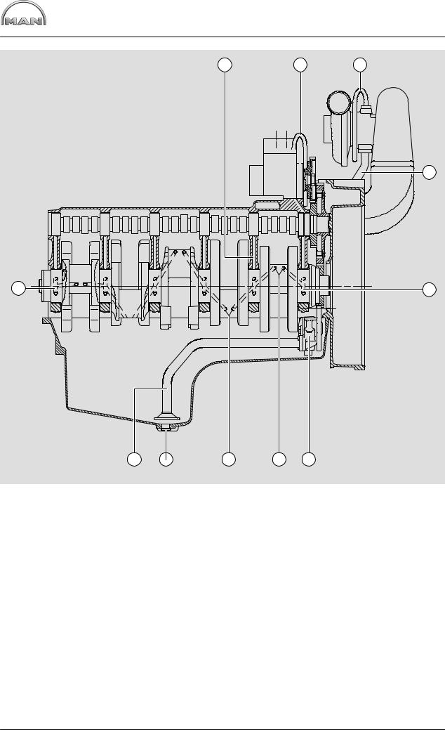
Engine lubrication schedule
5 |
9 |
8 |
1 |
2 |
7 |
7 |
6 |
3 |
4 |
5 |
À Oil line to crankshaft |
Å Oil pump with oil pressure relief valves |
Á High−pressure pump lubrication |
Æ Holes for conrod bearing lubrication |
 Lubricating oil lines to exhaust turbochargers |
Ç Oil drain screw |
à Oil return line from exhaust turbochargers |
È Oil intake pipe |
Ä Holes for main bearing lubrication |
|
20
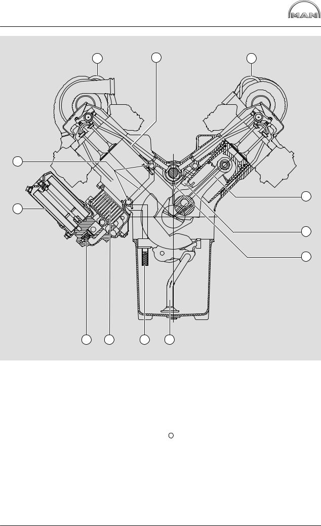
Engine lubrication schedule
1 |
2 |
1 |
11 |
3
10 |
4 |
5
9 |
8 |
7 |
6 |
À Lubricating oil lines to exhaust turbochargers Á Rocker arm lubrication
 Piston pin lubrication
ÃSpray nozzles for piston cooling and cam lubrication
Ä Camshaft bearing lubrication
Å Oil intake pipe
Æ Oil pressure relief valves Ç Oil cooler
È Bypass valve É Oil filter
11 Main oil galleries
21
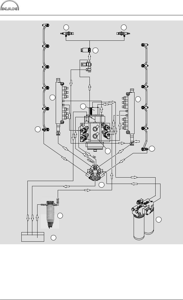
Fuel diagram
10
4
3
2
1
À Tank
Á Fuel prefilter with water separator  Injector
à Rail
Ä High pressure pump
10
9
4
6
2 3 1 4
5 |
3 |
|
8
7
Å Fuel pump Æ Fuel filter
Ç Fuel distributor È Solenoid valve É Glow plug
22
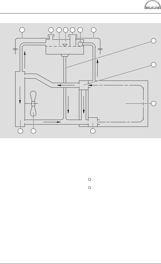
Schematic diagram of cooling system
1 |
2 |
3 |
4 |
5 |
6 |
1 |
7 |
8 |
9 |
12 |
11 |
10 |
À Overflow and vent pipe |
Æ |
Filler pipe |
Á Positive pressure / negative pressure valve |
Ç |
Thermostat |
 Coolant level in surge tank |
È |
Engine / crankcase |
à Surge tank |
É |
Water pump |
Ä Coolant filler neck |
11 |
Fan |
Å Degassing system |
12 |
Radiator / intercooler |
23
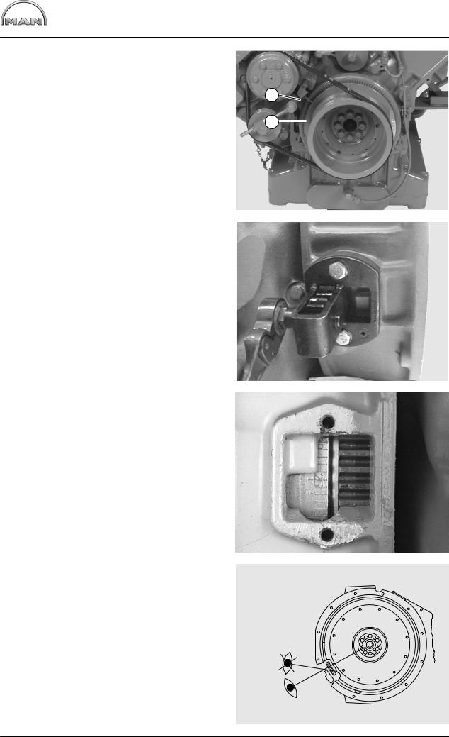
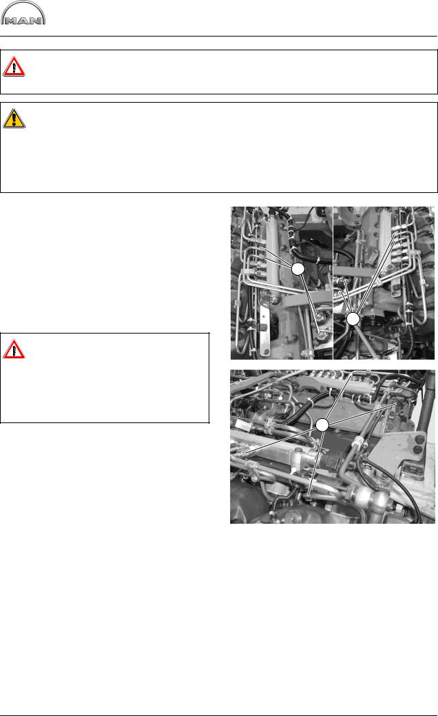
Check the base fitting of the high−pressure pump
Check the base fitting of the high− pressure pump
Fig. 1 and Fig. 2
For the purpose of checking the start−of−delivery setting, an “OT” (= TDC) mark and a scale from 10...50° before TDC are engraved on a disc Á fitted in front of the torsional vibration damper.
The scale marks are read against an indicator À fitted to the crankcase.
To turn the engine over manually during the setting 1 work, a plate with a central hexagon bolt must be located on the front side of the crankshaft pulley.
For this purpose, the speed pickup together with the plate is to be previously detached.
2
Fig. 3
The graduated scale on the flywheel, which is visible through the inspection hole in the flywheel housing, is often difficult to access. However it must be used to readjust the indicator after the vibration damper has been removed or replaced.
For this purpose, before the vibration damper with scale disc is installed, the engine must be set to “TDC” using the flywheel marking.
The indicator must then be aligned so that its measuring edge points exactly to the “TDC” mark
on the scale disc.
3
Fig. 4
To avoid read−off errors, always look over the notch on the flywheel housing vertically to the centre of the flywheel.
The marking on the graduated scale must be on the imaginary “notch − flywheel centre” line.
4
1
2
24
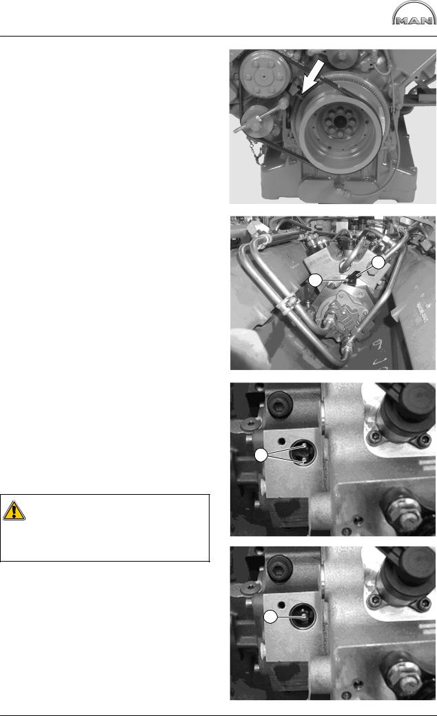
Check the base fitting of the high−pressure pump
Fig. 5
The indicator (arrow) must then be aligned so that its measuring edge points exactly to the “TDC” mark on the scale disc.
Turn engine to ignition TDC 1.
Fig. 6
Pull the connector off the rpm sensor Á.
Unscrew the mounting bolt À of the rpm sensor Á and pull out the rpm sensor.
No marking may be visible.
Fig. 7
If the engine is now turned back to 69° before TDC, 2 markings À must be visible.
If both markings are visible, then fit the rpm sensor and tighten the mounting bolt with 9 Nm.
Reconnect the control unit.
Fig. 9
Caution:
If only 1 marking is visible, the high−pressure pump has been fitted and twisted by 180° towards ignition TDC engine cylinder 1.
In this case, the high-pressure pump has to be removed.
5
7
1 |
8
1 |
9
2 |
1 |
25
Removing and installing the high-pressure lines
Danger:
Before starting the work, comply with “Special instructions when working on the common rail system” (see page 9).
Caution:
All connections and removed parts are to be closed immediately with suitable caps! Dirt in the injection system causes:
Dinjectors to jam
Dthe high-pressure pump drive to break The lines contain fuel.
Catch escaping fuel in a suitable container.
Fig. 1
Unscrew the union nuts À of the high-pressure lines between the rail and high-pressure pump.
Fig. 2
Unscrew the union nuts Á of the high-pressure lines between the rail and injectors.
The lines are installed in reverse order.
Danger:
High-pressure lines with WAF 17 union 1 nuts must be replaced!
High-pressure lines with WAF 19 union nuts may be reused!
Injection lines must be fitted without tension.
Tightening torques for high-pressure lines:
Initial fit: |
|
|
Pretightening |
10 Nm |
|
Final tightening |
60° |
|
Reuse: |
|
|
Pretightening |
10 Nm |
2 |
Final tightening |
30° |
|
1 |
1 |
2 |
26
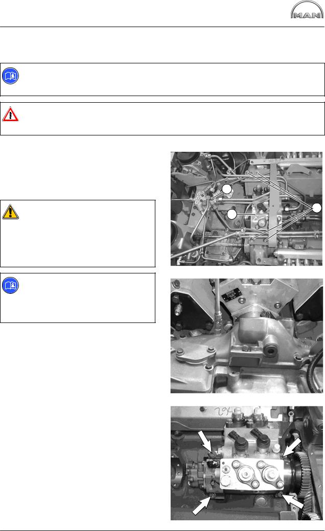
Removing and installing high-pressure pump
Removing high-pressure pump
D Remove the high-pressure lines between the high-pressure pump and rail, see page 26
Note:
The subsequent reinstallation of the high-pressure pump is rendered considerably easier if before its removal the engine has been turned to ignition TDC cylinder 1(see page 24).
Danger:
Before starting the work, comply with ”Special instructions when working on the common rail system” (see page 9).
Fig. 1
Unscrew and remove all fuel and oil lines to the high-pressure pump Á and to fuel distributor Â. Undo all the electrical connections to the highpressure pump.
Caution:
All connections and removed parts are to be closed immediately with suitable caps!
The lines contain fuel!
Catch escaping fuel in a suitable container.
Note:
To facilitate reassembly, memorise or mark down in a drawing or photo the positions of the brackets, pipe clamps and spacer sleeves etc.
To remove the injection pump, the high-pressure pump drive must be made accessible.
For this purpose the fuel distributor must be detached.
Close shutoff valve from tank to engine.
Fig. 2
Remove timing case cover.
The injection pump drive can now be seen.
Fig. 3
Remove mounting bolts from high-pressure pump (arrow).
Take off high-pressure pump.
1
2
3 |
2 |
1 |
|
3
27
Removing and installing high-pressure pump
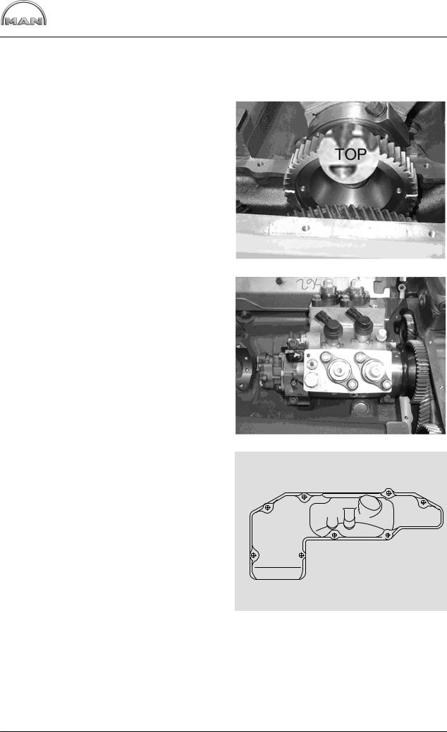
Installing high-pressure pump
D Turn engine to ignition TDC 1.
Fig. 4
Turn mark “TOP” on the high-pressure pump drive gear in the middle to pump.
Insert high-pressure pump.
4
Fig. 5
Tighten the mounting bolts in the sequence and method specified (pos. 1−4).
Order of tightening: 1−2−3−4 in the steps:
1. Initial torque: |
10−15 Nm |
2. final torque: |
65−70 Nm |
Check the base fitting of the high-pressure pump, see page 24.
3 1
2 4
Fig. 6
Tighten bolts on timing case cover to the torque and in the sequence specified.
Tightening torque: 25 Nm
Refit all components previously removed.
5
1 |
3 |
5 |
6 |
|
8 |
7 |
4 |
2 |
|
|
6
28
Loading...