


TABLE OF FLASHCODES
FOR FAULT MEMORIES
SD 206-2.97 e Page 1 of 62
Note:
For notes on setting and repair of individual systems please consult the Repair Manuals or the relevant Service Information sheets.
Notes/additions
SD 206-2.97
Page 2 of 62
Index
ABS/ASR |
|
|
Þ 2E Bosch......................................................................... |
Page |
4 - 5 |
Þ 3E Bosch......................................................................... |
Page |
6 - 7 |
Þ 2M Bosch ........................................................................ |
Page |
8 - 9 |
Þ 2M Stage 1 Bosch ........................................................... |
Page |
10 - 11 |
Þ CI 12 Bosch .................................................................... |
Page |
12 - 15 |
Þ Knorr ............................................................................... |
Page |
16 - 17 |
Þ Wabco "C"....................................................................... |
Page |
18 - 21 |
Running gear: |
|
|
Þ ECAS, buses................................................................... |
Page |
22 - 24 |
Þ ECAS, trucks................................................................... |
Page |
26 - 27 |
Þ EFR running gear control, trucks ..................................... |
Page |
28 - 30 |
Gearboxes: |
|
|
Þ Automated pre-selector shift (AVS) ................................. |
Page |
40 - 41 |
Þ Renk Doromat ................................................................. |
Page |
42 - 43 |
Þ SAMT B........................................................................... |
Page |
44 - 45 |
Þ Voith-Diwa 3.................................................................... |
Page |
46 - 47 |
Þ Voith retarder .................................................................. |
Page |
48 - 49 |
Þ ZF HP 500....................................................................... |
Page |
52 - 54 |
Þ ZF retarder (Intarder)....................................................... |
Page |
50 - 51 |
Heating/air-conditioning |
|
|
Þ D1LCC/D3LCC, Eberspächer.......................................... |
Page |
32 - 33 |
Þ Heater controls, Dreiha.................................................... |
Page |
34 - 35 |
Þ Air-conditioner, Behr........................................................ |
Page |
36 - 37 |
Þ Heater/air-conditioner control, Wabco (ATC) ................... |
Page |
38 - 39 |
Þ Airtop 2000, Webasto...................................................... |
Page |
31 |
Engine: |
|
|
Þ EDC M7 .......................................................................... |
Page |
56 - 57 |
Þ EDC MS5 ........................................................................ |
Page |
58 - 59 |
Þ EMS 3.3 .......................................................................... |
Page |
55 |
Þ Speed limiter VDO AGB-S .............................................. |
Page |
60 - 61 |
Þ Air injection, Wabco ........................................................ |
Page |
62 |
Door control, IFE .................................................................. |
Page |
25 |
|
SD 206-2.97 |
|
|
Page 3 of 62 |
|
BOSCH ABS/ASR 2E
Reading out the fault memory
−Switch off ignition and connect up request button
−Switch on ignition and press button for more than 1 second
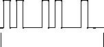
The fault codes are emitted in three blocks. The first block indicates which control unit status (configuration) is set. In the second and third blocks the faults in the diagonals FL/RR (second block) and FR/RL (third block) can be read out.
Pause between flashes ............................................................ |
approx. 0.5 s |
Duration of flashes ................................................................... |
approx. 0.5 s |
Pause between individual blocks ............................................. |
approx. 1.5 s |
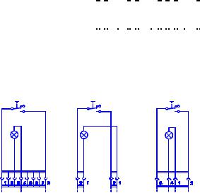
Example of flashcode: Flashcode 2 in Block 1 for an ABS unit, flashcode 2 in Block 2 and flashcode 1 in Block 3.
Lamp in |
on |
request |
|
button |
|
|
off |
Block 1 |
Block 2 |
Block 3 |
|
|
|
Erasing the fault memory
−Switch off ignition and connect up request button
−Press button and keep it pressed
−Switch on ignition and release button after > 3 seconds
SD 206-2.97
Page 4 of 62
Block 1: |
Flashcode |
ABS unit ................................................................................................................ |
2 |
ABS unit with ASR engine control (not an MAN application)) ................................ |
3 |
ABS unit with ASR brake control (not an MAN application) ................................... |
4 |
ABS unit with ASR brake and engine control.................................................... |
5 |
Flashcodes 3 and 4 may be emitted if components are not connected up or are defective.
Block 2 (FL/RR) and Block 3 (FR/RL): |
|
Fault type |
Flashcode |
No fault................................................................................................................... |
1 |
Control unit defective ............................................................................................. |
2 |
Speed sensor signal path: |
|
Þ front: inadmissible gap ...................................................................................... |
3 |
Þ rear: inadmissible gap ....................................................................................... |
4 |
Þ front: crack or short-circuit ................................................................................. |
6 |
Þ rear: crack or short-circuit.................................................................................. |
7 |
Undervoltage, or relay for pressure control valve cannot be triggered .................. |
9 |
Pressure control valve signal path: |
|
Þ front ................................................................................................................. |
10 |
Þ rear .................................................................................................................. |
11 |
Relay for pressure control valve cannot switch (sticking)) ................................... |
13 |
Signal path for ASR solenoid valve...................................................................... |
14 |
Connection diagram for request button |
|
Bus X40 |
X201 |
X202 |
X202 |
X124 |
|
|
|
SD 206-2.97
Page 5 of 62

BOSCH ABS/ASR 3E
Reading out the fault memory
−Switch off ignition and connect up request button
−Switch on ignition
−Press button for > 2 seconds
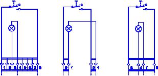
Blocks 1 and 2 indicate the configuration of the control unit. In Blocks 3 and 4 the faults in the diagonals FL/CR/RL (Block 3) and FR/CL/RR (Block 4) can be read out.
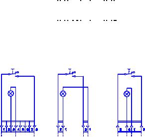
Example of flashcode: Flashcode 2 in Block 1, Flashcode 2 in Block 2, |
Flashcode 3 in |
||||||||||||||||||||||||
Block 3 and Flashcode 1 in Block 4. |
|
|
|
|
|
|
|
|
|
|
|
|
|
|
|
|
|
|
|
||||||
Lamp in |
|
|
|
|
|
|
|
|
|
|
|
|
|
|
|
|
|
|
|
|
|
|
|
|
|
on |
|
|
|
|
|
|
|
|
|
|
|
|
|
|
|
|
|
|
|
|
|
|
|||
request |
|
|
|
|
|
|
|
|
|
|
|
|
|
|
|
|
|
|
|
|
|
|
|
|
|
button |
|
|
|
|
|
|
|
|
|
|
|
|
|
|
|
|
|
|
|
|
|
|
|
|
|
|
off |
|
|
|
|
|
|
|
|
|
|
|
|
|
|
|
|
|
|
|
|
|
|
|
|
|
|
Block 1 |
|
Block 2 |
|
Block 3 |
|
Block 4 |
|
||||||||||||||||
|
|
|
|
|
|
||||||||||||||||||||
|
|
|
|
|
|
|
|
|
|
|
|
|
|
|
|
|
|
|
|
|
|
|
|
|
|
Erasing the fault memory
−Switch off ignition and connect up request button
−Press button and keep it pressed
−Switch on ignition and release button after > 3 seconds
Connection diagram for request button
Bus X40 |
X201 |
X202 |
X202 |
X124 |
|
|
|
SD 206-2.97
Page 6 of 62
Block 1: |
Flashcode |
ABS unit ............................................................................................................................ |
2 |
ABS unit with ASR engine control (not an MAN application) ............................................. |
3 |
ABS unit with ASR brake control at rear (not an MAN application).................................... |
4 |
ABS unit with ASR brake control at rear and engine control ...................................... |
5 |
ABS unit with ASR brake control in centre (not an MAN application) ................................ |
6 |
ABS unit with ASR brake control in centre and engine control |
|
(not an MAN application).................................................................................................... |
7 |
ABS unit with ASR brake control at rear and in centre |
|
(not an MAN application).................................................................................................... |
8 |
ABS unit with ASR brake control at rear and in centre and engine control |
|
(not an MAN application).................................................................................................... |
9 |
Flashcodes 3, 4, 6, 7, 8 and 9 may occur if components are defective or not connected up.
Block 2: |
Flashcode |
24 V operation, modified individual control on front axle ................................................... |
2 |
Block 3 (FL/CR/RL) and Block 4 (FR/CL/RR): |
|
Type of fault |
Flashcode |
No fault............................................................................................................................... |
1 |
Control unit defective ......................................................................................................... |
2 |
Speed sensor signal path: |
|
Þ front: inadmissible gap .................................................................................................. |
3 |
Þ centre: inadmissible gap................................................................................................ |
4 |
Þ rear: inadmissible gap ................................................................................................... |
5 |
Þ front: crack or short-circuit ............................................................................................. |
6 |
Þ centre: crack or short-circuit .......................................................................................... |
7 |
Þ rear: crack or short-circuit.............................................................................................. |
8 |
Undervoltage, or relay for pressure control valves cannot be triggered............................. |
9 |
Signal path for pressure control valve: |
|
Þ front ............................................................................................................................. |
10 |
Þ centre........................................................................................................................... |
11 |
Þ rear .............................................................................................................................. |
12 |
Relay for pressure control valve cannot switch (sticking) ................................................ |
13 |
Signal path for ASR solenoid valve.................................................................................. |
14 |
Inadmissible configuration (incorrect solenoid valve may be fitted)................................. |
15 |
SD 206-2.97
Page 7 of 62
BOSCH ABS/ASR 2M
Reading out the fault memory
-Switch off ignition and connect up request button
-Switch on ignition
-Press button for > 1 second
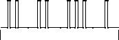
Blocks 1 and 2 indicate the configuration to which the control unit is set. In Blocks 3 and 4 the faults in the diagonals FL/RR (Block 3) and FR/RL (Block 4) can be read out.
Duration of a flash .................................................................... |
approx. 0,2 s |
Pause between flashes ............................................................ |
approx. 0,4 s |
Pause between blocks ............................................................. |
approx. 1,5 s |
Example of flashcode: Flashcode 2 in Block 1, Flashcode 2 in Block 2, Flashcode 3 in Block 3 and Flashcode 1 in Block 4.
Lamp in |
on |
request |
|
button |
|
|
off |
Block 1 |
Block 2 |
Block 3 |
Block 4 |
|
|
|
|
Erasing the fault memory
-Switch off ignition and connect up request button
-Press button and keep it pressed
-Switch on ignition and release button after > 2 seconds
ASR check lamp: |
Continually on: fault in servomotor path |
|
Dimmed permanent light: fault in signal at terminal W |
Gap recognition from control unit 81.25935-6410 onwards
-Drive vehicle at speed > 20 km/h
-Stop vehicle and switch off ignition
-Switch on ignition
ÞGap in order: ABS lamp continually on.
ÞGap enlarged: ABS lamp flashes 3 x and then remains continually on. Adjust speed sensors and accelerate vehicle several times from standstill to > 20 km/h so that the control unit can adjust to the change in the gaps.
SD 206-2.97
Page 8 of 62
Block 1: |
Flashcode |
ABS unit with HGB (from control unit 81.25935-6410)...................................... |
2 |
ABS unit with ASR engine control and HGB (not an MAN application).................. |
3 |
ABS unit with ASR brake control (not an MAN application) ................................... |
4 |
ABS unit with ASR brake and engine control and HGB ................................... |
5 |
Flashcodes 3 and 4 may occur if components are defected or not connected up.
Block 2: |
Flashcode |
24 V operation: individual control modified on front axle ....................................... |
2 |
Block 3 (FL/RR) and Block 4 (FR/RL): |
|
Type of fault |
Flashcode |
No fault................................................................................................................... |
1 |
Control unit defective ............................................................................................. |
2 |
Speed sensor signal path: |
|
Þ front: inadmissible gap or short-circuit............................................................... |
3 |
Þ rear: inadmissible gap or short-circuit ............................................................... |
4 |
Þ front: crack or short-circuit ................................................................................. |
5 |
Þ rear: crack or short-circuit.................................................................................. |
6 |
Undervoltage or relay for pressure control valve cannot be triggered ................... |
7 |
Pressure control valve signal path: |
|
Þ front ................................................................................................................... |
9 |
Þ rear .................................................................................................................. |
10 |
Relay for pressure control valve cannot switch (sticking) .................................... |
13 |
Signal path for ASR solenoid valve...................................................................... |
14 |
Connection diagram for request button |
|
Bus X40 |
X201 |
X202 |
X202 |
X124 |
|
|
|
SD 206-2.97
Page 9 of 62
BOSCH ABS/ASR 2M Stage 1
Reading out the fault memory
−Switch off ignition and connect up request button
−Switch on ignition
−Press button for > 1 second
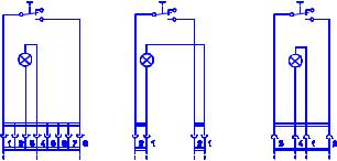
Blocks 1 and 2 indicate the configuration to which the control unit is set. In Blocks 3 and 4 the faults in the diagonals FL/RR (Block 3) and FR/RL (Block 4) can be read out.
Duration of a flash ............................................................................................ |
|
|
|
|
|
|
|
|
|
|
|
|
|
|
|
|
|
|
|
|
|
|
|
|
|
|
|
|
|
approx. 0.2 s |
|||
Pause between flashes .................................................................................... |
|
|
|
|
|
|
|
|
|
|
|
|
|
|
|
|
|
|
|
|
|
|
|
|
|
|
|
|
|
approx. 0.4 s |
|||
Pause between blocks ..................................................................................... |
|
|
|
|
|
|
|
|
|
|
|
|
|
|
|
|
|
|
|
|
|
|
|
|
|
|
|
|
|
approx. 1.5 s |
|||
Example of flashcode: Flashcode 2 in Block 1, Flashcode 2 in Block 2, |
|
|
|
|
|
||||||||||||||||||||||||||||
Flashcode 3 in Block 3 and Flashcode 1 in Block 4. |
|
|
|
|
|
||||||||||||||||||||||||||||
Lamp in |
on |
|
|
|
|
|
|
|
|
|
|
|
|
|
|
|
|
|
|
|
|
|
|
|
|
|
|
|
|
|
|
||
|
|
|
|
|
|
|
|
|
|
|
|
|
|
|
|
|
|
|
|
|
|
|
|||||||||||
request |
|
|
|
|
|
|
|
|
|
|
|
|
|
|
|
|
|
|
|
|
|
|
|
|
|
|
|
|
|
|
|
|
|
button |
|
|
|
|
|
|
|
|
|
|
|
|
|
|
|
|
|
|
|
|
|
|
|
|
|
|
|
|
|
|
|
|
|
|
off |
|
|
|
|
|
|
|
|
|
|
|
|
|
|
|
|
|
|
|
|
|
|
|
|
|
|
|
|
|
|
|
|
|
|
Block 1 |
|
Block 2 |
|
Block 3 |
|
Block 4 |
|
||||||||||||||||||||||||
|
|
|
|
|
|
||||||||||||||||||||||||||||
|
|
|
|
|
|
|
|
|
|
|
|
|
|
|
|
|
|
|
|
|
|
|
|
|
|
|
|
|
|
|
|
|
|
Erasing the fault memory
−Switch off ignition and connect up request button
−Press button and keep it pressed
−Switch on ignition and release button after > 3 seconds
Connection diagram for request button
Bus X40 |
X201 |
X202 |
X202 |
SD 206-2.97
Page 10 of 62
Block 1: |
Flashcode |
ABS unit with HGB............................................................................................................... |
2 |
ABS unit with ASR engine control and HGB (not an MAN application).................................. |
3 |
ABS unit with ASR brake control and HGB (not an MAN application) ................................... |
4 |
ABS unit with ASR brake and engine control and HGB ................................................... |
5 |
Flashcodes 3 and 4 may occur if components are defective or not connected up. |
|
Block 2: |
Flashcode |
24 V operation: individual control modified on front axle ....................................................... |
2 |
Block 3 (FL/RR) and Block 4 (FR/RL): |
|
Type of fault |
Flashcode |
No fault................................................................................................................................... |
1 |
Control unit defective ............................................................................................................. |
2 |
Speed sensor signal path: |
|
Þ front: inadmissible gap or short-circuit............................................................................... |
3 |
Þ rear: inadmissible gap or short-circuit ............................................................................... |
4 |
Þ front: crack or short-circuit ................................................................................................. |
6 |
Þ rear: crack or short-circuit.................................................................................................. |
7 |
Undervoltage or relay for pressure control valves cannot be triggered.................................. |
9 |
Pressure control valve signal path: |
|
Þ front ................................................................................................................................. |
10 |
Þ rear .................................................................................................................................. |
11 |
Relay for pressure control valve cannot switch (sticking) .................................................... |
13 |
Signal path for ASR control valve ........................................................................................ |
14 |
Fault in servomotor .............................................................................................................. |
15 |
Fault in C3/B7-Signal ........................................................................................................... |
16 |
Fault in signal at terminal W ................................................................................................ |
17 |
Wheel equalisation difference too large............................................................................... |
18 |
Fault in signal path for relay for engine brake/retarder switch-off |
|
(emission possible only in Block 4) ...................................................................................... |
19 |
Fault in signal path for clutch switch .................................................................................... |
20 |
Gap recognition
-Drive vehicle at > 20 km/h
-Stop vehicle and switch off ignition
-Switch on ignition
ÞGap in order: ABS lamp is continually on.
ÞGap enlarged: ABS lamp flashes 3x and then remains continually on.
Adjust speed sensors and accelerate vehicle several times from standstill to > 20 km/h so that the control unit can adjust to the changed gaps.
SD 206-2.97
Page 11 of 62

BOSCH ABS/ASR CI 12
Reading out the fault memory
−Switch off ignition and connect up request button
−Switch on ignition
−Wait for 2 seconds and then press button for at least 2 seconds.
The flashcodes are emitted in two blocks. Block 1 indicates the configuration to which the control unit is set. Block 2 indicates the actual fault code. Each fault code must be requested individually.
Pause before first flash .................................................................................... |
approx. 3 s |
Duration of a flash ............................................................................................ |
approx. 0.5 s |
Pause between hundreds and tens or tens and units....................................... |
approx. 3 s |
Pause between hundreds and hundreds .......................................................... |
approx. 1 s |
Pause between tens and tens .......................................................................... |
approx. 1 s |
Pause between units and units......................................................................... |
approx. 1 s |
Example of flashcode: Flashcode 5 in Block 1, Flashcode 121 in Block 2.
Lamp in |
on |
|
|
|
|
|
|
|
|
|
|
|
|
|
|
|
request |
|
|
|
|
|
|
|
|
|
|
|
|
|
|
|
|
button |
|
|
|
|
|
|
|
|
|
|
|
|
|
|
|
|
|
off |
|
|
|
|
|
|
|
|
|
|
|
|
|
|
|
Erasing the fault memory |
|
|
Block 1 |
|
|
|
|
|
|
Block 2 |
||||||
|
|
|
|
|
|
|
|
|
|
|
|
|
|
|
|
|
−Switch off ignition and connect up request button
−Press the button
−Switch on ignition and keep button pressed for > 2 seconds
−Do not switch off ignition until at least 5 seconds have passed.
Connection diagram for request button
X202
SD 206-2.97
Page 12 of 62
Block 1: |
Flashcode |
Pure ABS unit, modified individual control on front axle |
.................................................2 |
ABS unit with ASR engine control (not an MAN application) |
.................................................3 |
ABS unit with ASR brake control (not an MAN application) ................................................... |
4 |
ABS unit with ASR brake and engine control.................................................................... |
5 |
Pure ABS unit with Select-Low control on front axle |
|
(not an MAN application)........................................................................................................ |
6 |
ABS unit with Select-Low control on front axle and |
|
ASR engine control (not an MAN application)........................................................................ |
7 |
ABS unit with Select-Low control on front axle and |
|
ASR brake control (not an MAN application) ......................................................................... |
8 |
ABS unit with Select-Low control on front axle and |
|
ASR brake and engine control (not an MAN application)....................................................... |
9 |
Flashcodes 3, 4, 6, 7, 8 and 9 may occur if components are defective or not connected up.
Block 2: |
|
Type of fault |
Flashcode |
No fault............................................................................................................................... |
121 |
CAN data bus: |
|
Þ BusOff, repair CAN bus ................................................................................................. |
211 |
Þ Tachograph signal, plausibility ...................................................................................... |
212 |
Þ Communication interrupted, repair CAN bus................................................................. |
213 |
Þ Time-out, gearbox messages, repair CAN bus ............................................................. |
214 |
Þ Time-out, engine messages, repair CAN bus................................................................ |
215 |
Þ Time-out, retarder messages, repair CAN bus.............................................................. |
216 |
Brake light switch not yet actuated, check cabling............................................................. |
217 |
Control unit defective ......................................................................................................... |
221 |
Control unit defective ......................................................................................................... |
222 |
Control unit defective ......................................................................................................... |
223 |
Control unit defective ......................................................................................................... |
224 |
Control unit defective ......................................................................................................... |
225 |
Control unit defective ......................................................................................................... |
226 |
Control unit defective ......................................................................................................... |
227 |
Configuration EEPROM parameters defective................................................................... |
228 |
Axle tyres or pulse ring incorrect........................................................................................ |
232 |
Voltage supply to pressure control valve, undervoltage..................................................... |
242 |
Voltage supply to pressure control valve, interruption ....................................................... |
243 |
Control unit defective ......................................................................................................... |
244 |
Pressure control valve: |
|
Þ Earth, FR or RL, control unit output, short-circuit to earth ............................................. |
251 |
Þ Earth, FR or RL, control unit output, short-circuit to +UBatt .......................................... |
252 |
Þ Earth, diagonal FR/RL, interruption (PIN X1, 12) .......................................................... |
253 |
Þ Voltage supply, diagonal FR/RL, incorrect polarity of +/-.............................................. |
254 |
Þ Earth, FL or RR, control unit output, short-circuit to earth ............................................. |
255 |
Þ Earth, FL or RR, control unit output, short-circuit to +UBatt .......................................... |
256 |
|
SD 206-2.97 |
|
Page 13 of 62 |
Pressure control valve: |
|
Þ Earth, diagonal FL/RR, interruption (PIN X1, 11) .......................................................... |
257 |
Þ Voltage supply, diagonal FL/RR, incorrect polarity of +/-.............................................. |
258 |
Speed sensors: |
|
Þ RL, interruption/short-circuit .......................................................................................... |
312 |
Þ RL, pulse ring defective, gap too large.......................................................................... |
316 |
Þ FL, interruption/short-circuit........................................................................................... |
322 |
Þ FL, pulse ring defective, gap too large .......................................................................... |
326 |
Þ RR, interruption/short-circuit.......................................................................................... |
342 |
Þ RR, pulse ring defective, gap too large ......................................................................... |
346 |
Þ FR, interruption/short-circuit .......................................................................................... |
362 |
Þ FR, pulse ring defective, gap too large.......................................................................... |
366 |
Þ RL, interturn fault, gap, pole wheel, signal .................................................................... |
411 |
Þ RL, tyres or pulse ring incorrect .................................................................................... |
415 |
Þ FL, interturn fault, gap, pole wheel, signal..................................................................... |
421 |
Þ FL, tyres or pulse ring incorrect..................................................................................... |
425 |
Speed sensors: |
|
Þ RR, interturn fault, gap, pole wheel, signal.................................................................... |
441 |
Þ RR, tyres or pulse ring incorrect.................................................................................... |
445 |
Þ FR, interturn fault, gap, pole wheel, signal .................................................................... |
461 |
Þ FR, tyres or pulse ring incorrect .................................................................................... |
465 |
Pressure control valve: |
|
Þ FL, inlet valve, interruption ............................................................................................ |
512 |
Þ FL, inlet valve, short-circuit to earth .............................................................................. |
513 |
Þ FL, inlet valve, short-circuit to +UBatt ........................................................................... |
514 |
Þ FL, earth connection, interruption.................................................................................. |
515 |
Þ FL, outlet valve, interruption .......................................................................................... |
516 |
Þ FL, outlet valve, short-circuit to earth ............................................................................ |
517 |
Þ FL, outlet valve, short-circuit to +UBatt ......................................................................... |
518 |
Þ RL, inlet valve, interruption............................................................................................ |
522 |
Þ RL, inlet valve, short-circuit to earth .............................................................................. |
523 |
Þ RL, inlet valve, short-circuit to +UBatt ........................................................................... |
524 |
Þ RL, earth connection, interruption.................................................................................. |
525 |
Þ RL, outlet valve, interruption.......................................................................................... |
526 |
Þ RL, outlet valve, short-circuit to earth............................................................................ |
527 |
Þ RL, outlet valve, short-circuit to +UBatt......................................................................... |
528 |
Þ RR, inlet valve, interruption ........................................................................................... |
532 |
Þ RR, inlet valve, short-circuit to earth ............................................................................. |
533 |
Þ RR, inlet valve, short-circuit to +UBatt .......................................................................... |
534 |
Þ RR, earth connection, interruption................................................................................. |
535 |
Þ RR, outlet valve, interruption ......................................................................................... |
536 |
Þ RR, outlet valve, short-circuit to earth ........................................................................... |
537 |
Þ RR, outlet valve, short-circuit to +UBatt ........................................................................ |
538 |
Þ FR, inlet valve, interruption............................................................................................ |
552 |
SD 206-2.97
Page 14 of 62
Block 2: |
|
Type of fault |
Flashcode |
Pressure control valve: |
|
Þ FR, inlet valve, short-circuit to earth.............................................................................. |
553 |
Þ FR, inlet valve, short-circuit to +UBatt........................................................................... |
554 |
Þ FR, earth connection, interruption ................................................................................. |
555 |
Þ FR, outlet valve, interruption ......................................................................................... |
556 |
Þ FR, outlet valve, short-circuit to earth............................................................................ |
557 |
Þ FR, outlet valve, short-circuit to +UBatt......................................................................... |
558 |
Þ FL, short-circuit to another valve ................................................................................... |
611 |
Þ FL, incorrectly configured .............................................................................................. |
616 |
Þ RL, short-circuit to another valve................................................................................... |
621 |
Þ RR, short-circuit to another valve .................................................................................. |
631 |
Þ FR, short-circuit to another valve................................................................................... |
651 |
Þ FR, incorrectly configured ............................................................................................. |
656 |
ASR solenoid valve: |
|
Þ Interruption .................................................................................................................... |
712 |
Þ Short-circuit to earth ...................................................................................................... |
713 |
Þ Short-circuit to +UBatt ................................................................................................... |
714 |
Þ Short-circuit to another valve......................................................................................... |
721 |
Þ Recognised but not configured...................................................................................... |
726 |
Interaxle lock/shut-off valve, short-circuit to earth.............................................................. |
811 |
Interaxle lock/shut-off valve, short-circuit to +UBatt ........................................................... |
812 |
Engine interface: |
|
Þ DKR, short-circuit to earth or +UBatt............................................................................. |
813 |
Þ DKV, actuator reports fault ............................................................................................ |
814 |
Þ DKV, interruption/short-circuit........................................................................................ |
815 |
Þ DKV, time-out ................................................................................................................ |
816 |
Triggering of relay for engine brake/retarder: |
|
Þ Short-circuit to +UBatt ................................................................................................... |
817 |
Þ Interruption or short-circuit to earth ............................................................................... |
818 |
SD 206-2.97
Page 15 of 62
KNORR ABS
Reading out the fault memory
−Switch off ignition and connect up request button
−Switch on ignition and wait for 2 seconds
−Press button for 2 seconds
The first block indicates the configuration to which the control unit is set. The second block indicates the fault codes. Each fault code must be requested individually.
Duration of a ten............................................................................................... |
|
|
|
|
|
|
|
|
|
|
|
|
|
|
|
|
|
|
|
approx. 2 s |
Duration of a unit .............................................................................................. |
|
|
|
|
|
|
|
|
|
|
|
|
|
|
|
|
|
|
|
approx. 0.5 s |
Pause between tens and units ......................................................................... |
|
|
|
|
|
|
approx. 3 s |
|||||||||||||
Pause between units and units......................................................................... |
|
|
|
|
|
|
approx. 1 s |
|||||||||||||
Pause between tens and tens .......................................................................... |
|
|
|
|
|
|
|
|
|
|
|
|
|
|
|
|
|
|
|
approx. 1 s |
Example of flashcode: Flashcode 2 in Block 1 and Flashcode 12 in Block 2. |
||||||||||||||||||||
Lamp in |
on |
|
|
|
|
|
|
|
|
|
|
|
|
|
|
|
|
|||
|
|
|
|
|
|
|
|
|
|
|
|
|
|
|
|
|
||||
request |
|
|
|
|
|
|
|
|
|
|
|
|
|
|
|
|
|
|
|
|
button |
|
|
|
|
|
|
|
|
|
|
|
|
|
|
|
|
|
|
|
|
|
off |
|
|
|
|
|
|
|
|
|
|
|
|
|
|
|
|
|
|
|
|
|
Block 1 |
|
Block 2 |
|
|||||||||||||||
|
|
|
|
|||||||||||||||||
|
|
|
|
|
|
|
|
|
|
|
|
|
|
|
|
|
|
|
|
|
Erasing the fault memory
−Switch of ignition and connect up request button
−Press button and keep it pressed
−Switch on ignition and release it after > 2 seconds
Connection diagram for request button
X124 |
X201 |
X202 |
X202 |
SD 206-2.97
Page 16 of 62
Block 1: |
Flashcode |
ABS unit without ASR.......................................................................................................... |
2 |
ABS unit with ASR engine control (not an MAN application) ................................................. |
3 |
ABS unit with ASR brake control (not an MAN application) ................................................... |
4 |
ABS unit with ASR brake and engine control (not an MAN application) ................................ |
5 |
Flashcodes 3, 4 and 5 may occur if components are defective or not connected up.
Block 2 (Diagonal 1 FR/RL, Diagonal 2 FL/RR): |
|
Type of fault |
Flashcode |
No fault................................................................................................................................... |
1 |
Speed sensors: |
|
Þ FL, interruption or short-circuit......................................................................................... |
10 |
Þ FL, gap too large, interturn fault, pole wheel fault ........................................................... |
11 |
Þ FR, interruption or short-circuit ........................................................................................ |
12 |
Þ FR, gap too large, interturn fault, pole wheel fault........................................................... |
13 |
Þ RL, interruption or short-circuit ........................................................................................ |
14 |
Þ RL, gap too large, interturn fault, pole wheel fault........................................................... |
15 |
Þ RR, interruption or short-circuit........................................................................................ |
16 |
Þ RR, gap too large, interturn fault, pole wheel fault........................................................... |
17 |
Pressure control valve: |
|
Þ FL, interruption or short-circuit......................................................................................... |
22 |
Þ FR, interruption or short-circuit ........................................................................................ |
23 |
Þ RL, interruption or short-circuit ........................................................................................ |
24 |
Þ RR, interruption or short-circuit........................................................................................ |
25 |
ASR brake valve, RL, interruption or short-circuit ................................................................ |
28 |
ASR brake valve, RR, interruption or short-circuit ............................................................... |
29 |
ASR engine control, E-Gas/EDC interface fault................................................................... |
31 |
Relay voltage supply for pressure control valve: |
|
Þ Diagonal 1 cannot be switched off (contact sticking)....................................................... |
32 |
Þ Diagonal 1 cannot be switched off................................................................................... |
33 |
Þ Diagonal 2 cannot be switched off (contact sticking)....................................................... |
34 |
Þ Diagonal 2 cannot be switched off................................................................................... |
35 |
ABS engine brake/retarder switch-off, interruption or short-circuit....................................... |
36 |
ABS warning lamp, tractor, interruption or short-circuit........................................................ |
38 |
Switch-on time monitoring of valves (implausible triggering)............................................... |
52 |
ASR recognised but not configured...................................................................................... |
53 |
Differences in wheel diameter too large............................................................................... |
54 |
Voltage supply for pressure-control valves, diagonal 1, overvoltage................................... |
56 |
Voltage supply for pressure-control valves, diagonal 2, overvoltage................................... |
57 |
Speed recording, signals with frequency > 1500 Hz, unwanted signals .............................. |
91 |
Pressure control valves, bleeding and holding times too long ............................................. |
92 |
Configuration error (defective EEPROM parameters).......................................................... |
98 |
Control unit defective ........................................................................................................... |
99 |
SD 206-2.97
Page 17 of 62

WABCO „C“ ABS/ASR
Reading out the fault memory
−Switch-off ignition and connect up request switch
−Switch on ignition and wait for 2 seconds
−Close the switch
If the switch is opened the fault entry in the fault memory will be erased. Switching off the ignition before the switch is opened ends the flashcode emission without erasing the fault in the fault memory. The first block is a "starting block"; this begins the fault code emission. The second block indicates the configuration to which the control unit is set. Blocks 3 and 4 indicate the actual fault codes. The flashcode emission may be deactivated (ended) only in the pauses between the constantly repeated flashcodes.
Duration of starting block ................................................................................. |
approx. 2.5 s |
Pause between blocks ..................................................................................... |
approx. 2.5 s |
Duration of a flash ............................................................................................ |
approx. 0.5 s |
Pause between flashes .................................................................................... |
approx. 0,5 s |
Example of flashcode: Starting block (Block1), Flashcode 2 in Block 2,
|
Flashcode 6 in Block 3 and Flashcode 6 in Block 4. |
||||||||||||||||||||||||||||
|
|
|
|
|
|
|
|
|
|
|
|
|
|
|
|
|
|
|
|
|
|
|
|
|
|
|
|
|
|
Lamp in |
on |
|
|
|
|
|
|
|
|
|
|
|
|
|
|
|
|
|
|
|
|
|
|
|
|
|
|
||
request |
|
|
|
|
|
|
|
|
|
|
|
|
|
|
|
|
|
|
|
|
|
|
|
|
|
|
|
|
|
switch |
|
|
|
|
|
|
|
|
|
|
|
|
|
|
|
|
|
|
|
|
|
|
|
|
|
|
|
|
|
|
off |
|
|
|
|
|
|
|
|
|
|
|
|
|
|
|
|
|
|
|
|
|
|
|
|
|
|
|
|
|
Block 1 |
|
Block 2 |
|
|
Block 3 |
|
|
|
Block 4 |
|||||||||||||||||||
|
|
|
|
|
|
|
|
||||||||||||||||||||||
|
|
|
|
|
|
|
|
|
|
|
|
|
|
|
|
|
|
|
|
|
|
|
|
|
|
|
|
|
|
Erasing the fault memory
−Switch off ignition and connect up request switch
−Switch on ignition and wait for 2 seconds
−Close the switch
−Open the switch during flashcode emission.
Connection diagram for request switch
X202
SD 206-2.97
Page 18 of 62
Block 2: |
|
|
|
Flashcode |
|
ABS system 6S/6K................................................................................................................. |
|
1 |
ABS system 4S/4K................................................................................................................. |
|
2 |
ABS system 4S/3K................................................................................................................. |
|
3 |
ABS system 6S/4K................................................................................................................. |
|
4 |
ABS system 6S/3K................................................................................................................. |
|
5 |
Flashcodes 3, 4 and 5 may occur if parts are defective or not connected up. |
|
|
Block 3 and Block 4: |
|
|
Type of fault |
Flashcode |
|
|
Block 3 |
Block 4 |
Valve relay FR/RL, undervoltage ........................................................................... |
6 |
.............6 |
Valve relay FL/RR, undervoltage ........................................................................... |
6 ............. |
7 |
Speed sensor: |
|
|
Þ FR, wheel speed signal fault (failure) ................................................................ |
6 ............. |
8 |
Þ FL, wheel speed signal fault (failure)................................................................. |
6 ............. |
9 |
Þ FR, interruption or short-circuit in cable ............................................................ |
6 ........... |
10 |
Þ FL, interruption or short-circuit in cable ............................................................. |
6 ........... |
11 |
Þ FR, wheel speed signal implausible.................................................................. |
6 ........... |
12 |
Þ FL, wheel speed signal implausible .................................................................. |
6 ........... |
13 |
Þ RL, wheel speed signal fault (failure) ................................................................ |
7 ............. |
0 |
Þ RR, wheel speed signal fault (failure)................................................................ |
7 ............. |
1 |
Þ RL, interruption of short-circuit in cable............................................................. |
7 ............. |
2 |
Þ RR, interruption or short-circuit in cable ............................................................ |
7 ............. |
3 |
Þ RL, wheel speed signal implausible .................................................................. |
7 ............. |
4 |
Þ RR, wheel speed signal implausible ................................................................. |
7 ............. |
5 |
Þ ML, wheel speed signal fault (failure)................................................................ |
7 ............. |
8 |
Þ MR, wheel speed signal fault (failure) ............................................................... |
7 ............. |
9 |
Þ ML, inadmissible impedance, interruption/short-circuit ..................................... |
7 ........... |
10 |
Þ MR, interruption or short-circuit in cable............................................................ |
7 ........... |
11 |
Þ ML, wheel speed signal implausible.................................................................. |
7 ........... |
12 |
Þ MR, wheel speed signal implausible ................................................................. |
7 ........... |
13 |
Control unit defective ............................................................................................. |
8 ............. |
0 |
Control unit defective ............................................................................................. |
8 ............. |
1 |
ASR proportional valve (not an MAN application).................................................. |
8 ............. |
2 |
ASR interface, DKR signal, interruption in cable (PIN 29) ..................................... |
8 ............. |
3 |
ASR proportional valve (not an MAN application).................................................. |
8 ............. |
4 |
ASR interface, DKV signal, faulty data transfer (PIN 28) ....................................... |
8 ............. |
5 |
Interface for V signal (not an MAN application)...................................................... |
8 ............. |
6 |
ASR interface, DKV signal, interruption in cable (PIN 28) ..................................... |
8 ............. |
7 |
ASR interface, DKV signal, faulty data transfer (PIN 28) ....................................... |
8 ............. |
9 |
SD 206-2.97
Page 19 of 62
 Loading...