


Makita LS1016F, LS1016, LS1016FL Manual
|
GB |
Slide Compound Miter Saw |
Instruction Manual |
|
|
|
|
|
|
Scie à Onglet Radiale |
Manuel d’instructions |
|
F |
||
|
|
|
|
|
|
Kappund Gehrungssäge |
Betriebsanleitung |
|
D |
||
|
|
|
|
|
|
Sega combinata a slitta |
Istruzioni per l’uso |
|
I |
||
|
|
|
|
|
|
Schuifbare afkortverstekzaag |
Gebruiksaanwijzing |
|
NL |
||
|
|
|
|
|
|
Sierra de Inglete Telescópica |
Manual de instrucciones |
|
E |
||
|
|
|
|
|
|
Serra de Esquadria c/ Braço Telescópico |
Manual de instruções |
|
P |
||
|
|
|
|
|
|
Afkorter-geringssav |
Brugsanvisning |
|
DK |
||
|
|
|
|
|
|
Δισκ πρί ν σύνθετης λ τ μής μήκ υς |
δηγίες ρήσεως |
|
GR |
||
|
|
λίσθησης |
|
|
|
|
LS1016
LS1016L
LS1016F
LS1016FL
1 |
|
2 |
|
|
|
|
2 |
2 |
|
|
1 |
2 |
3 |
3 |
|
3 |
4 |
4
5
5  6
6
4
7 |
8 |
9 |
6
2
90 |
10 |
7 |
12 |
|
|
14 |
|
|
15 |
|
|
13 |
8 |
|
|
|
17 |
18 |
|
16 |
|
|
|
|
|
|
14 |
9 |
|
10 |
|
|
19 |
|
20 |
10 |
|
|
|
|
|
21 |
|
|
22 |
11 |
12 |
3

23
13
24


27


26
25
15
28
29
23

30
17
91
92
19
4
 24
24
14 |
90 |
10 |
16 |
29
28
30
18
 31
31
20
|
19 |
|
21 |
|
|
33 |
|
|
|
32 |
|
23 |
|
|
34 |
2 |
|
32 |
||
|
||
|
3 |
|
25 |
|
|
37 |
37 |
|
36 |
5 |
|
27 |
|
A |
B |
22
1
24 |
|
|
|
|
|
35 |
36 |
|
|
|
2 |
26 |
|
|
|
2 |
38 |
5 |
41 |
|
|
|
|
|
|
39 |
40 |
|
|
|
|
28 |
|
|
|
|
|
|
5 |
m |
|
|
2 |
29 |
|
|
45 |
47 |
46 |
31 |
|
|
48 |
|
45 |
33 |
|
|
23 |
|
52 |
35 |
|
6 |
|
43 42
44
30
 48
48
|
45 |
|
49 |
32 |
|
50 |
51 |
34 |
|
53 |
54 |
93 |
|
36 |
|
37 |
 55
55
58 59
39
11 |
55 |
57 |
56 |
38 |
40 |
60
 11
11
41 |
90 |
10 |
43 |
42
44
7
52 |
38 |
61
45 |
45 |
62 |
45 |
45 |
63
45
(1) (2) |
(3)(4) |
64 65
47
 66 67
66 67 51
51
46
64 |
(2) |
(1) |
|
|
|
(1) |
(2) |
|
|
(2) |
(4) |
|
65 |
|
(3) |
|
|
||
|
|
|||
(1) |
|
|
|
|
(2) |
|
|
(1) |
|
(1) |
|
|
(2) |
|
48
 68 69
68 69
51 |
49 |
50 |
18
18 |
71 |
|
72
73
72
70
51 |
52 |
8 |
|
74 |
1 |
53 |
54 |
55
11
 27 76
27 76
57
24
 23
23
78
59


 75
75
56
27 


 23
23


77
58
75
5
16
60
9
77


27
61
82
83
63
 85
85

 86
86  87
87
65
88
67
10


 27
27 


 79
79
80 81
62
84
64
87
66
85
 89
89
68
Symbols
The followings show the symbols used for the equipment. Be sure that you understand their meaning before use.
Symboles
Nous donnons ci-dessous les symboles utilisés pour l’outil. Assurez-vous que vous en avez bien compris la signification avant d’utiliser l’outil.
Symbole
Die folgenden Symbole werden für die Maschine verwendet. Machen Sie sich vor der Benutzung unbedingt mit ihrer Bedeutung vertraut.
Symboli
Per questo utensile vengono usati i simboli seguenti. Bisogna capire il loro significato prima di usare l’utensile.
Symbolen
Voor dit gereedschap worden de volgende symbolen gebruikt. Zorg ervoor dat u de betekenis van deze symbolen begrijpt alvorens het gereedschap te gebruiken.
Símbolos
A continuación se muestran los símbolos utilizados con esta herramienta. Asegúrese de que entiende su significado antes de usarla.
Símbolos
O seguinte mostra os símbolos utilizados para a ferramenta. Certifique-se de que compreende o seu significado antes da utilização.
Symboler
Nedenstående symboler er anvendt i forbindelse med denne maskine. Vær sikker på, at De har forstået symbolernes betydning, før maskinen anvendes.
Σύμ λα
Τα ακ λ υθα δεί ν υν τα σύμ λα π υ ρησιμ π ι ύνται για τ μη άνημα. Βε αιωθείτε τι καταλα αίνετε τη σημασία τ υς πριν απ τη ρήση.
• Read instruction manual. |
• Lea el manual de instrucciones. |
• Lire le mode d’emploi. |
• Leia o manual de instruções. |
• Bitte Bedienungsanleitung lesen. |
• Læs brugsanvisningen. |
• Leggete il manuale di istruzioni. |
• Δια άστε τις δηγίες ρήσης. |
• Lees de gebruiksaanwijzing. |
|
• |
|
• DOUBLE INSULATION |
• DOBLE AISLAMIENTO |
• DOUBLE ISOLATION |
• DUPLO ISOLAMENTO |
• DOPPELT SCHUTZISOLIERT |
• DOBBELT ISOLERET |
• DOPPIO ISOLAMENTO |
• ΔΙΠΛΗ Μ$ΝΩΣΗ |
•DUBBELE ISOLATIE
•To avoid injury from flying debris, keep holding the saw head down, after making cuts, until the blade has come to a complete stop.
•Pour éviter les blessures causées par les objets projetés, maintenez la tête de la scie en posi-
tion basse une fois la coupe terminée, jusqu’à ce que la lame soit complètement arrêtée.
• Um Verletzungen durch herausgeschleuderte Teile zu vermeiden, halten Sie den Sägekopf nach Ausführung von Schnitten abgesenkt, bis das Sägeblatt völlig zum Stillstand gekommen ist.
•Per evitare lesioni dalle schegge volanti, dopo aver eseguito il taglio tenere abbassata la testa sega finché la lama non si è arrestata completamente.
•Om verwonding door weggeslingerd zaagafval te voorkomen, dient u na het voltooien van een snede de zaagkop omlaag te houden totdat het zaagblad volledig tot stilstand is gekomen.
•Para evitar sufrir heridas a causa de restos que salen despedidos, siga sujetando la cabeza de la sierra hacia abajo, al terminar los cortes, hasta que el disco se haya parado completamente.
•Para evitar danos causados por aparas que saltem, mantenha a cabeça da serra para baixo, depois de terminar os cortes, até que a lâmina esteja completamente parada.
•For at undgå at komme til skade på grund af flyvende affald, skal man holde savhovedet nede efter skæring, indtil savklingen står helt stille.
•Για να απ φύγετε τραυματισμ απ ιπτάμενα τεμα ίδια, κρατάτε τ πρι νι με τ κεφάλι πρ ς τα κάτω, αφ ύ κάνετε κ πές, μέ ρι η λάμα να σταματήσει τελείως.
11
1 |
2 |
3 |
•When performing slide cut, first pull carriage fully and press down handle, then push carriage toward the guide fence.
•Lorsque vous effectuez une coupe en glissière, tirez d’abord complètement le chariot et abaissez la poignée, puis poussez le chariot vers le guide.
•Ziehen Sie den Schlitten zur Ausführung von Schiebeschnitten zunächst ganz vor, drücken Sie den Griff nach unten, und schieben Sie dann den Schlitten zum Gehrungsanschlag.
•Per eseguire un taglio di scorrimento, tirare prima completamente il carrello, premere giù il manico e spingere poi il carrello verso la guida pezzo.
•Bij drukkend (glijdend) zagen, dient u eerst de slede volledig naar u toe te trekken en het handvat omlaag te drukken. Duw daarna de slede naar de geleider toe.
•Cuando haga cortes de deslizamiento, primero tire del carro completamente y presione hacia abajo la empuñadura, después empuje el carro hacia la guía lateral.
•Quando executa corte corrediço, puxe primeiro o carro completamente e empurre a pega para baixo e em seguida empurre o carro na direcção da placa guia.
•Når man udfører savning ved gliden, skal man først trække slæden helt og trykke håndtaget ned og derefter trykke slæden mod anslaget.
•$ταν εκτελείτε λισθητική κ πή, πρώτα τρα ή τε την κινητή άση πλήρως και πατήστε την λα ή κάτω, μετά σπρώ τε την κινητή άση πρ ς τ ν φρά τη δηγ .
•Do not place hand or fingers close to the blade.
•Ne pas placer les mains ou les doigts près de la lame.
•Halten Sie Hände oder Finger vom Sägeblatt fern.
•Non avvicinare le mani o le dita alla lama.
•Kom met uw handen of vingers niet te dicht bij het zaagblad.
•No ponga la mano ni los dedos cerca del disco.
•Não coloque a sua mão ou dedos perto da lâmina.
•Hold hænder og fingre på god afstand af klingen.
•Μη ά-ετε τ έρι ή τα δάκτυλα κ ντά στην λάμα.
•Never look into the laser beam. Direct laser beam may injure your eyes.
•Ne jamais regarder directement la source du faisceau laser. L’exposition directe au faisceau laser comporte un risque de blessure aux yeux.
•Blicken Sie auf keinen Fall in den Laserstrahl. Der direkte Laserstrahl kann Ihre Augen verletzen.
•Mai guardare direttamente il raggio laser. Il raggio laser può danneggiare gli occhi.
•Kijk nooit in de laserstraal. Een directe laserstraal kan oogletsel veroorzaken.
•No mire nunca directamente al rayo láser. El rayo láser directo puede dañar sus ojos.
•Nunca olhe para o raio laser. Se olhar directamente para o raio laser pode ferir os seus olhos.
•Se aldrig ind i laserstrålen. Direkte udsættelse for laserstråling kan skade dit syn.
•Π τέ μη κυττάτε απευθείας την ακτίνα λέι-ερ. Η απευθείας ακτίνα λέι-ερ μπ ρεί να πρ καλέσει τραυματισμ στα μάτια σας.
12

• Only for EU countries
Do not dispose of electric equipment together with household waste material!
In observance of European Directive 2002/96/EC on waste electrical and electronic equipment and its implementation in accordance with national law, electric equipment that have reached the end of their life must be collected separately and returned to an environmentally compatible recycling facility.
• Pour les pays européens uniquement
Ne pas jeter les équipements électriques dans les ordures ménagères !
Conformément à la directive européenne 2002/96/EG relative aux déchets d’équipements électriques ou électroniques (DEEE), et à sa transposition dans la législation nationale, les équipements électriques doivent être collectés à part et être soumis à un recyclage respectueux de l’environnement.
• Nur für EU-Länder
Werfen Sie Elektrogeräte nicht in den Hausmüll!
Gemäß Europäischer Richtlinie 2002/96/EG über Elektround Elektronik-Altgeräte und Umsetzung in nationales Recht müssen verbrauchte Elektrogeräte getrennt gesammelt und einer umweltgerechten Wiederverwertung zugeführt werden.
• Solo per Paesi UE
Non gettare le apparecchiature elettriche tra i rifiuti domestici.
Secondo la Direttiva Europea 2002/96/CE sui rifiuti di apparecchiature elettriche ed elettroniche e la sua attuazione in conformità alle norme nazionali, le apparecchiature elettriche esauste devono essere raccolte separatamente, al fine di essere riciclate in modo eco-compatibile.
• Alleen voor EU-landen
Geef elektrische apparaten niet met het huisvuil mee!
Volgens de Europese richtlijn 2002/96/EG inzake oude elektrische en elektronische apparaten en de toepassing daarvan binnen de nationale wetgeving, dient gebruikt elektrische apparaten gescheiden te worden ingezameld en te worden afgevoerd naar een recycle bedrijf dat voldoet aan de geldende milieu-eisen.
• Sólo para países de la Unión Europea
¡No deseche los aparatos eléctricos junto con los residuos domésticos!
De conformidad con la Directiva Europea 2002/96/CE sobre residuos de aparatos eléctricos y electrónicos y su aplicación de acuerdo con la legislación nacional, los aparatos eléctricos cuya vida útil haya llegado a su fin se deberán recoger por separado y trasladar a una planta de reciclaje que cumpla con las exigencias ecológicas.
• Apenas para países da UE
Não deite ferramentas eléctricas no lixo doméstico!
De acordo com a directiva europeia 2002/96/CE sobre ferramentas eléctricas e electrónicas usadas e a sua aplicação para as leis nacionais, as ferramentas eléctricas usadas deven ser recolhidas em separado e encaminhadas a uma instalação de reciclagem dos materiais ecológicos.
• Kun for EU-lande
Elværktøj må ikke bortskaffes som almindeligt affald!
I henhold til det europæiske direktiv 2002/96/EF om bortskaffelse af elektriske og elektroniske produkter og gældende national lovgivning skal brugt elværktøj indsamles separat og returneres til miljøgodkendt genindvinding.
• Μ ν για τις ώρες της ΕΕ
Μη πετάτε τα είδη ηλεκτρικ ύ ε0 πλισμ ύ μα-ί με τα ικιακά απ ρρίμματα.
Σε τήρηση της Eυρωπαϊκής Oδηγίας 2002/96/ΕΚ, περί απ ρριμμάτων ειδών ηλεκτρικ ύ και ηλεκτρ νικ ύ ε0 πλισμ ύ και την εφαρμ γή της σύμφωνα με την εθνική ν μ θεσία, τα είδη ηλεκτρικ ύ ε0 πλισμ ύ π υ έ υν φθάσει στ τέλ ς της -ωής τ υς πρέπει να συλλέγ νται 0ε ωριστά και να επιστρέφ νται σε μιά περι αλλ ντικά συμ ατή εγκατάσταση ανακύκλωσης.
13

ENGLISH (Original instructions)
Explanation of general view
1 |
Stopper pin |
34 |
Center cover |
66 |
Crown molding stopper L |
2 |
Hex bolt(s) |
35 |
Shaft lock |
|
(Optional accessory) |
3 |
Blade guard |
36 |
Blade case |
67 |
Crown molding stopper R |
4 |
Kerf board |
37 |
Arrow |
|
(Optional accessory) |
5 |
Saw blade |
38 |
Outer flange |
68 |
Crown molding stopper L |
6 |
Blade teeth |
39 |
Inner flange |
69 |
Crown molding stopper R |
7 |
Left bevel cut |
40 |
Spindle |
70 |
Crown molding |
8 |
Straight cut |
41 |
Ring |
71 |
Vise |
9 |
Right bevel cut |
42 |
Dust nozzle |
72 |
Spacer block |
10 |
Lock lever |
43 |
Dust bag |
73 |
Aluminum extrusion |
11 |
Screw |
44 |
Fastener |
74 |
Cut grooves with blade |
12 |
Adjusting bolt |
45 |
Dust box |
75 |
Triangular rule |
13 |
Turn base |
46 |
Cover |
76 |
Miter scale |
14 |
Stopper lever |
47 |
Button |
77 |
Bevel scale plate |
15 |
Slide pipe |
48 |
Cylinder section |
78 |
0° Angle adjusting bolt |
16 |
Top surface of turn base |
49 |
Sawdust |
79 |
Scale plate |
17 |
Periphery of blade |
50 |
Support |
80 |
Left 45° bevel angle adjusting |
18 |
Guide fence |
51 |
Turn base |
|
bolt |
19 |
Adjusting screw |
52 |
Clamping screws |
81 |
Right 45° bevel angle adjusting |
20 |
Stopper arm |
53 |
Upper fence |
|
bolt |
21 |
Grip |
54 |
Lower fence |
82 |
Workpiece |
22 |
Cam |
55 |
Vise knob |
83 |
Laser line |
23 |
Lever(s) |
56 |
Vise arm |
84 |
Vertical vise |
24 |
Latch lever |
57 |
Vise rod |
85 |
Screwdriver |
25 |
Scale plate |
58 |
Vise plate |
86 |
Screw (one piece only) |
26 |
Release button |
59 |
Vise nut |
87 |
Lens for the laser light |
27 |
Pointer |
60 |
Holder |
88 |
Limit mark |
28 |
Lock-off button |
61 |
52/38° type crown molding |
89 |
Brush holder cap |
29 |
Switch trigger |
62 |
45° type crown molding |
90 |
Locking screw |
30 |
Hole for padlock |
63 |
45° type cove molding |
91 |
Switch for light |
31 |
Switch for laser |
64 |
Inside corner |
92 |
Light |
32 |
Socket wrench |
65 |
Outside corner |
93 |
Red indicating area |
33 |
Wrench holder |
|
|
|
|
|
|
|
|
|
|
SPECIFICATIONS |
|
|
|
|
|
Model |
|
|
LS1016/LS1016L/LS1016F/LS1016FL |
||
Blade diameter |
|
|
|
|
|
For all countries other than European countries ............................................................................. |
|
255 mm – 260 mm |
|||
For European countries.................................................................................................................................... |
|
|
|
260 mm |
|
Hole diameter |
|
|
|
|
|
For all countries other than European countries ............................................................................................. |
|
25.4 mm |
|||
For European countries...................................................................................................................................... |
|
|
|
30 mm |
|
Max. cutting capacities (H x W) with 260 mm in diameter
Miter angle |
|
Bevel angle |
|
|
|
|
|
||
|
45° (left) |
0° |
45° (right) |
|
|
|
|
|
|
0° |
42 mm x 310 mm |
68 mm x 310 mm |
29 mm x 310 mm |
|
|
|
|
||
58 mm x 279 mm |
91 mm x 279 mm |
43 mm x 279 mm |
||
|
||||
|
|
|
|
|
45° (right and left) |
42 mm x 218 mm |
68 mm x 218 mm |
29 mm x 218 mm |
|
|
|
|
||
58 mm x 197 mm |
91 mm x 197 mm |
43 mm x 197 mm |
||
|
||||
|
|
|
|
|
52° (right and left) |
– |
68 mm x 190 mm |
– |
|
|
||||
91 mm x 171 mm |
||||
|
|
|
||
|
|
|
|
|
60° (right) |
– |
68 mm x 155 mm |
– |
|
|
||||
91 mm x 139 mm |
||||
|
|
|
||
|
|
|
|
14

Special Max. Cutting capacities
Crown molding 45° type |
168 mm |
|
(with Crown molding stopper used) |
||
|
||
|
|
|
Base board (H) |
120 mm |
|
(with Horizontal vise used) |
||
|
||
|
|
No load speed (min–1) ............................................................................................................................................ |
3,200 |
Laser Type (LS1016L, LS1016FL)........................................................... |
Red Laser 650 nm, <1.6mW (Laser Class 2M) |
Dimensions (L x W x H) ..................................................................................................... |
718 mm x 640 mm x 671 mm |
Net weight |
|
For all countries other than European countries |
|
LS1016 .............................................................................................................................................................. |
23.6 kg |
LS1016L/LS1016F............................................................................................................................................. |
23.7 kg |
LS1016FL .......................................................................................................................................................... |
23.8 kg |
For European countries |
|
LS1016 .............................................................................................................................................................. |
24.1 kg |
LS1016L/LS1016F............................................................................................................................................. |
24.2 kg |
LS1016FL .......................................................................................................................................................... |
24.3 kg |
Safety class ............................................................................................................................................................. |
/II |
•Due to our continuing program of research and development, the specifications herein are subject to change without notice.
•Specifications may differ from country to country.
•Weight according to EPTA-Procedure 01/2003
Intended use
The tool is intended for accurate straight and miter cutting in wood. With appropriate saw blades, aluminum can also be sawed.
Power supply
The tool should be connected only to a power supply of the same voltage as indicated on the nameplate, and can only be operated on single-phase AC supply. They are double-insulated in accordance with European Standard and can, therefore, also be used from sockets without earth wire.
GEA010-1
General Power Tool Safety Warnings
 WARNING Read all safety warnings and all instructions. Failure to follow the warnings and instructions may result in electric shock, fire and/or serious injury.
Save all warnings and instructions for future reference.
ENB034-6
ADDITIONAL SAFETY RULES FOR TOOL
1.Wear eye protection.
2.Keep hands out of path of saw blade. Avoid contact with any coasting blade. It can still cause severe injury.
3.Do not operate saw without guards in place. Check blade guard for proper closing before each use. Do not operate saw if blade guard does not move freely and close instantly. Never clamp or tie the blade guard into the open position.
4.Do not perform any operation freehand. The workpiece must be secured firmly against the turn base and guide fence with the vise during all operations. Never use your hand to secure the workpiece.
5.Never reach around saw blade.
6.Turn off tool and wait for saw blade to stop before moving workpiece or changing settings.
7.Unplug tool before changing blade or servicing.
8.Always secure all moving portions before carrying the tool.
9.Stopper pin which locks the cutter head down is for carrying and storage purposes only and not for any cutting operations.
10.Do not use the tool in the presence of flammable liquids or gases. The electrical operation of the tool could create an explosion and fire when exposed to flammable liquids or gases.
11.Check the blade carefully for cracks or damage before operation.
Replace cracked or damaged blade immediately.
12.Use only flanges specified for this tool.
13.Be careful not to damage the arbor, flanges (especially the installing surface) or bolt. Damage to these parts could result in blade breakage.
14.Make sure that the turn base is properly secured so it will not move during operation.
15.For your safety, remove the chips, small pieces, etc. from the table top before operation.
16.Avoid cutting nails. Inspect for and remove all nails from the workpiece before operation.
17.Make sure the shaft lock is released before the switch is turned on.
18.Be sure that the blade does not contact the turn base in the lowest position.
19.Hold the handle firmly. Be aware that the saw moves up or down slightly during start-up and stopping.
20.Make sure the blade is not contacting the workpiece before the switch is turned on.
21.Before using the tool on an actual workpiece, let it run for a while. Watch for vibration or wobbling that could indicate poor installation or a poorly balanced blade.
22.Wait until the blade attains full speed before cutting.
23.Stop operation immediately if you notice anything abnormal.
24.Do not attempt to lock the trigger in the on position.
25.Be alert at all times, especially during repetitive, monotonous operations. Don’t be lulled into a false sense of security. Blades are extremely unforgiving.
15
26.Always use accessories recommended in this manual. Use of improper accessories such as abrasive wheels may cause an injury.
27.Do not use the saw to cut other than wood, aluminum or similar materials.
28.Connect miter saws to a dust collecting device when sawing.
29.Select saw blades in relation to the material to be cut.
30.Take care when slotting.
31.Replace the kerf board when worn.
32.Do not use saw blades manufactured from high speed steel.
33.Some dust created from operation contains chemicals known to cause cancer, birth defects or other reproductive harm. Some examples of these chemicals are:
•lead from lead-based-painted material and,
•arsenic and chromium from chemically-treated
lumber.
Your risk from these exposures varies, depending on how often you do this type of work. To reduce your exposure to these chemicals: work in a well ventilated area and work with approved safety equipment, such as those dust masks that are specially designed to filter out microscopic particles.
34.To reduce the emitted noise, always be sure that the blade is sharp and clean.
35.The operator is adequately trained in the use, adjustment and operation of the machine.
36.Use correctly sharpened saw blades. Observe the maximum speed marked on the saw blade.
37.Refrain from removing any cut-offs or other parts of the workpiece from the cutting area whilst the tool is running and the saw head is not in the rest position.
38.Use only saw blades recommended by the manufacturer which conform to EN847-1.
39.Wear gloves for handling saw blade (saw blades shall be carried in a holder wherever practicable) and rough material.
40.When fitted with laser, no exchange with different type of laser is permitted. Repairs shall only be carried out correctly.
SAVE THESE INSTRUCTIONS
INSTALLATION
Bench mounting
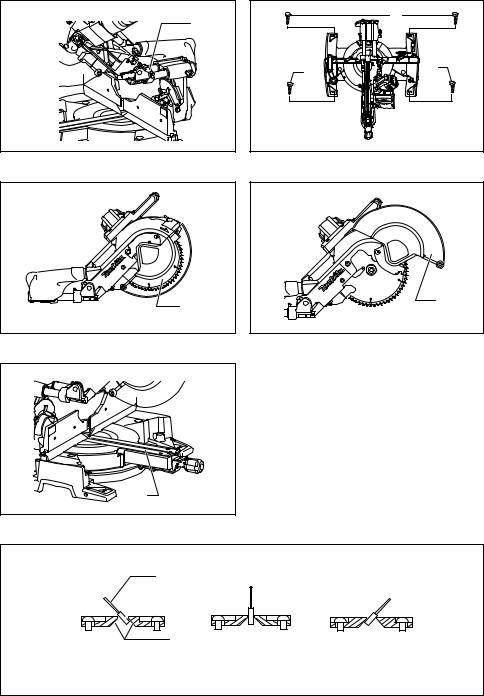
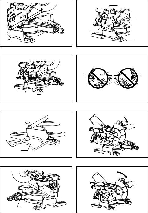
When the tool is shipped, the handle is locked in the lowered position by the stopper pin. Release the stopper pin by simultaneously applying a slight downward pressure on the handle and pulling the stopper pin. (Fig. 1)
WARNING:
•Ensure that the tool will not move on the supporting surface. Movement of the miter saw on the supporting surface while cutting may result in loss of
control and serious personal injury.
This tool should be bolted with four bolts to a level and stable surface using the bolt holes provided in the tool’s base. This will help prevent tipping and possible injury.
(Fig. 2)
FUNCTIONAL DESCRIPTION
WARNING:
•Always be sure that the tool is switched off and unplugged before adjusting or checking function on the tool. Failure to switch off and unplug the tool may result in serious personal injury from accidental start-up.
Blade guard (Fig. 3 & 4)
When lowering the handle, the blade guard rises automatically. The blade guard returns to its original position when the cut is completed and the handle is raised.
WARNING:
•Never defeat or remove the blade guard or the spring which attaches to the guard. An exposed blade as a result of defeated guarding may result in serious personal injury during operation.
In the interest of your personal safety, always maintain the blade guard in good condition. Any irregular operation of the blade guard should be corrected immediately. Check to assure spring loaded return action of guard.
WARNING:
•Never use the tool if the blade guard or spring are damaged, faulty or removed. Operation of the tool with a damaged, faulty or removed guard may result in serious personal injury.
If the see-through blade guard becomes dirty, or sawdust adheres to it in such a way that the blade and/or workpiece is no longer easily visible, unplug the saw and clean the guard carefully with a damp cloth. Do not use solvents or any petroleum-based cleaners on the plastic guard because this may cause damage to the guard.
If the blade guard becomes dirty and needs to be cleaned for proper operation follow the steps below: With the tool switched off and unplugged, use the supplied socket wrench to loosen the hex bolt holding the center cover. Loosen the hex bolt by turning it counterclockwise and raise the blade guard and center cover. With the blade guard so positioned, cleaning can be more completely and efficiently accomplished. When cleaning is complete, reverse procedure above and secure bolt. Do not remove spring holding blade guard. If guard becomes damaged through age or UV light exposure, contact a Makita service center for a new guard.
DO NOT DEFEAT OR REMOVE GUARD.
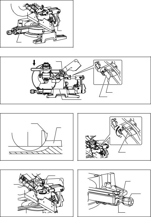
Positioning kerf board (Fig. 5, 6 & 7)
This tool is provided with the kerf boards in the turn base to minimize tearing on the exit side of a cut. The kerf boards are factory adjusted so that the saw blade does not contact the kerf boards. Before use, adjust the kerf boards as follows:
First, unplug the tool. Loosen all the screws (2 each on left and right) securing the kerf boards. Re-tighten them only to the extent that the kerf boards can still be easily moved by hand. Lower the handle fully and push in the stopper pin to lock the handle in the lowered position. Loosen the locking screw counterclockwise which secures the upper slide poles and also push forward the lock lever which secures the lower slide poles. Pull the carriage toward you fully. Adjust the kerf boards so that the kerf boards just contact the sides of the blade teeth. Tighten the front screws (do not tighten firmly). Push the carriage toward the guide fence fully and adjust the kerf boards so that the kerf boards just contact the sides of blade teeth. Tighten the rear screws (do not tighten firmly).
16
After adjusting the kerf boards, release the stopper pin and raise the handle. Then tighten all the screws securely.
NOTICE:
•After setting the bevel angle ensure that the kerf boards are adjusted properly. Correct adjustment of the kerf boards will help provide proper support of the workpiece minimizing workpiece tear out.
Maintaining maximum cutting capacity (Fig. 8, 9 & 10)
This tool is factory adjusted to provide the maximum cutting capacity for a 260 mm saw blade.
Unplug the tool before any adjustment is attempted. When installing a new blade, always check the lower limit position of the blade and if necessary, adjust it as follows: First, unplug the tool. Lower the stopper lever to position the saw blade as shown in the figure. Push the carriage toward the guide fence fully and lower the handle completely. Use the socket wrench to turn the adjusting bolt until the periphery of the blade extends slightly below the top surface of the turn base at the point where the front face of the guide fence meets the top surface of the turn base.
With the tool unplugged, rotate the blade by hand while holding the handle all the way down to be sure that the blade does not contact any part of the lower base. Readjust slightly, if necessary.
After adjustment, always return the stopper lever to the original position by turning it counterclockwise.
WARNING:
•After installing a new blade and with the tool unplugged, always be sure that the blade does not contact any part of the lower base when the handle is lowered completely. If a blade makes contact with the base it may cause kickback and result in serious personal injury.
Stopper arm (Fig. 11)
The lower limit position of the blade can be easily adjusted with the stopper arm. To adjust it, rotate the stopper arm in the direction of the arrow as shown in the figure. Adjust the adjusting screw so that the blade stops at the desired position when lowering the handle fully.
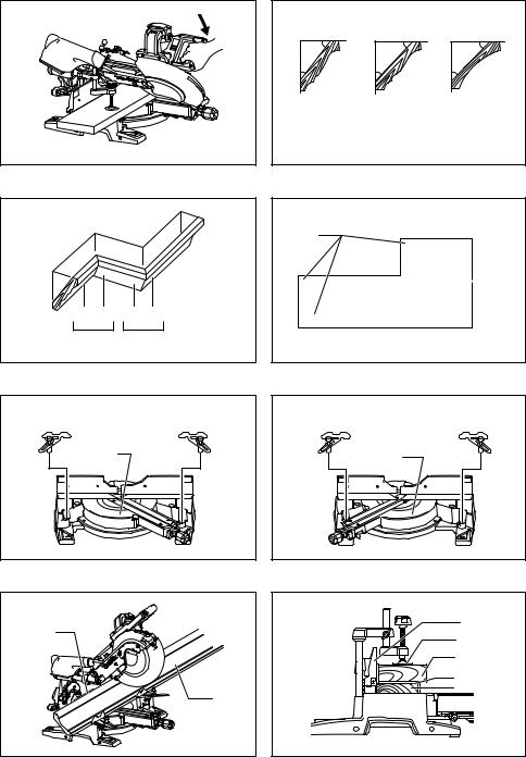
Adjusting the miter angle (Fig. 12)
Push the grip so that the cams engages and turn it clockwise until it stops. Turn the turn base while pressing down the lock lever. When you have moved the grip to the position where the pointer points to the desired angle on the miter scale, turn the grip 90° counterclockwise to lock the turn base.
CAUTION:
•After changing the miter angle, always secure the turn base by turning the grip 90° counterclockwise.
NOTICE:
•When turning the turn base, be sure to raise the handle fully.
Adjusting the bevel angle (Fig. 13, 14 & 15)
To adjust the bevel angle, loosen the lever at the rear of the tool counterclockwise. Push the latch lever forward as shown in the figure fully while supporting the weight of the saw head so as to release the pressure on the lock pin.
When tilting the carriage to the right, tilt the carriage to the left slightly after loosening the lever and press the releasing button. With the releasing button being pressed, tilt the carriage to the right.
Tilt the saw blade until the pointer points to the desired angle on the bevel scale. Then tighten the lever clockwise firmly to secure the arm.
When the latch lever is pulled towards the front of the saw, the saw blade can be locked using positive stops at the right and left 22.5 ° and 33.9 ° angle to the base surface.
When the latch lever is pushed to the back of the saw as shown in the figure, the saw blade can be locked at any desired angle within the specified bevel angle range.
CAUTION:
•After changing the bevel angle, always secure the arm by tightening the lever clockwise.
NOTICE:
•When tilting the saw blade be sure the handle is fully raised.
•When changing bevel angles, be sure to position the kerf boards appropriately as explained in the “Positioning kerf board” section.
Slide lock adjustment (Fig. 16)
To lock the lower slide pole, pull the lock lever towards the front of the saw.
To lock the upper slide pole, turn the locking screw clockwise.
Switch action
For European countries (Fig. 17)
To prevent the switch trigger from being accidentally pulled, a lock-off button is provided. To start the tool, push the lever to the left, press in the lock-off button and then pull the switch trigger. Release the switch trigger to stop.
WARNING:
•Before plugging in the tool, always check to see that the switch trigger actuates properly and returns to the “OFF” position when released. Do not pull the switch trigger hard without pressing in the lock-off button. This can cause switch breakage. Operating a tool with a switch that does not actuate properly can lead to loss of control and serious personal injury.
A hole is provided in the switch trigger for insertion of padlock to lock the tool off.
For all countries other than European countries (Fig. 18)
To prevent the switch trigger from being accidentally pulled, a lock-off button is provided. To start the tool, press in the lock-off button and pull the switch trigger. Release the switch trigger to stop.
WARNING:
•Before plugging in the tool, always check to see that the switch trigger actuates properly and returns to the “OFF” position when released. Do not pull the switch trigger hard without pressing in the lock-off button. This can cause switch breakage. Operating a tool with a switch that does not actuate properly can lead to loss of control and serious personal injury.
A hole is provided in the switch trigger for insertion of padlock to lock the tool off.
17
WARNING:
•Do not use a lock with a shank or cable any smaller than 6.35 mm in diameter. A smaller shank or cable may not properly lock the tool in the off position and unintentional operation may occur resulting in serious personal injury.
•NEVER use tool without a fully operative switch trigger. Any tool with an inoperative switch is HIGHLY DANGEROUS and must be repaired before further usage or serious personal injury may occur.
•For your safety, this tool is equipped with a lock-off button which prevents the tool from unintended starting. NEVER use the tool if it runs when you simply pull the switch trigger without pressing the lock-off button. A switch in need of repair may result in unintentional operation and serious personal injury. Return tool to a Makita service center for proper repairs BEFORE further usage.
•NEVER defeat the lock-off button by taping down or some other means. A switch with a defeated lock-off button may result in unintentional operation and serious personal injury.
Lighting up the lamps (Fig. 19)
For Models LS1016F and LS1016FL only CAUTION:
•This is not a rainproof light. Do not wash the light in water or use it in a rain or a wet area. Such a conduct can cause an electric shock and fume.
•Do not touch the lens of the light, as it is very hot while it is lighted or shortly after it is turned off. This may cause a burn to a human body.
•Do not apply impact to the light, which may cause damage or shorted service time to it.
•Do not keep casting the beam of the light to your eyes. This can cause your eyes to be hurt.
•Do not cover the light with clothes, carton, cardboard or similar objects while it is lighted, which can cause a fire or an ignition.
To turn on the light, press the upper position (I) of the switch. To turn off the light, press the lower position (O) of the switch.
Move the light to shift an area of lighting.
NOTE:
•Use a dry cloth to wipe the dirt off the lens of lamp. Be careful not to scratch the lens of light, or it may lower the illumination.
Electronic function
Constant speed control
•The tool is provided with an electronic speed control which helps maintain a constant blade rotation speed even under load. A constant blade rotation speed will result in a very smooth cut.
Soft start feature
•This function allows the smooth start-up of the tool by limiting the start-up torque.
Laser beam action
For Models LS1016L and LS1016FL only
CAUTION:
•Never look into the laser beam. Direct laser beam may injure your eyes.
•LASER RADIATION, DO NOT STARE INTO THE BEAM OR VIEW DIRECTLY WITH OPTICAL INSTRUMENTS, CLASS 2M LASER PRODUCT.
To turn on the laser beam, press the upper position (I) of the switch. To turn off the laser beam, press the lower position (O) of the switch. (Fig. 20)
Laser line can be shifted to either the left or right side of the saw blade by adjusting the adjusting screw as follows. (Fig. 21)
1.Loosen the adjusting screw by turning it counterclockwise.
2.With the adjusting screw loosened, slide the adjusting screw to the right or left as far as it goes.
3.Tighten the adjusting screw firmly at the position where it stops sliding.
Laser line is factory adjusted so that it is positioned within 1 mm from the side surface of the blade (cutting position).
NOTE:
•When laser line appears dim and hard to see because of direct sunlight, relocate the work area to a place where there is less direct sunlight.
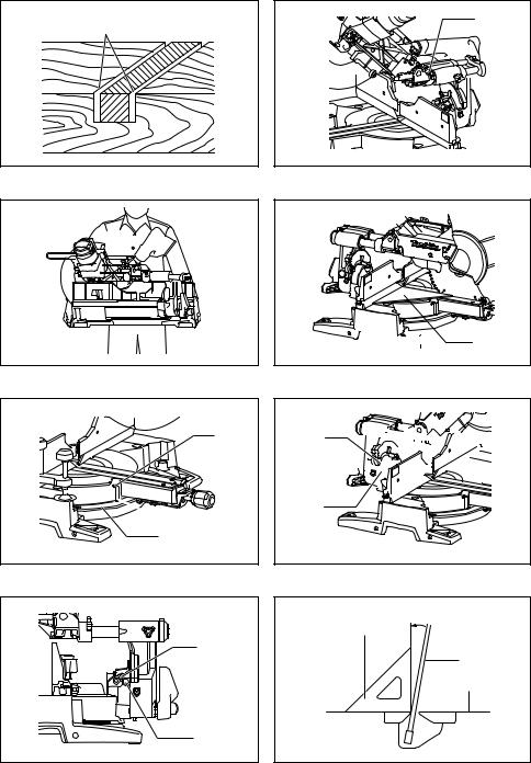
Aligning the laser line (Fig. 22)
Laser line can be shifted to either the left or right side of the blade according to the applications of cutting. Refer to explanation titled “Laser beam action” regarding its shifting method.
NOTE:
•Use wood facing against the guide fence when aligning the cutting line with the laser line at the side of guide fence in compound cutting (bevel angle 45 degrees and miter angle right 45 degrees).
A)When you obtain the correct size on the left side of workpiece
•Shift the laser line to the left of the blade.
B)When you obtain the correct size on the right side of workpiece
•Shift the laser line to the right of the blade.
Align the cutting line on your workpiece with the laser line.
ASSEMBLY
WARNING:
•Always be sure that the tool is switched off and unplugged before working on the tool. Failure to switch off and unplug the tool may result in serious personal injury.
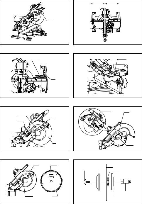
Socket wrench storage (Fig. 23)
The socket wrench is stored as shown in the figure. When the socket wrench is needed it can be pulled out of the wrench holder.
After using the socket wrench it can be stored by returning it to the wrench holder.
Installing or removing saw blade
WARNING:
•Always be sure that the tool is switched off and unplugged before installing or removing the blade.
Accidental start up of the tool may result in serious personal injury.
•Use only the Makita socket wrench provided to install or remove the blade. Failure to use the wrench may result in overtightening or insufficient tightening of the hex bolt and serious personal injury.
Lock the handle in the raised position by pushing in the stopper pin. (Fig. 24)
18
To remove the blade, use the socket wrench to loosen the hex bolt holding the center cover by turning it counterclockwise. Raise the blade guard and center cover.
(Fig. 25)
Press the shaft lock to lock the spindle and use the socket wrench to loosen the hex bolt clockwise. Then remove the hex bolt, outer flange and blade. (Fig. 26)
NOTE:
•If the inner flange is removed be sure to install it on the spindle with its protrusion facing away from the blade. If the flange is installed incorrectly the flange will rub against the machine.
WARNING:
•Before mounting the blade onto the spindle, always be sure that the correct ring for the blade's arbor hole you intend to use is installed between the inner and the outer flanges. Use of the incorrect arbor hole ring may result in the improper mounting of the blade causing blade movement and severe vibration resulting in possible loss of control during operation and in serious personal injury.
To install the blade, mount it carefully onto the spindle, making sure that the direction of the arrow on the surface of the blade matches the direction of the arrow on the blade case.
Install the outer flange and hex bolt, and then use the socket wrench to tighten the hex bolt (left-handed) securely counterclockwise while pressing the shaft lock.
(Fig. 27 & 28)
Return the blade guard and center cover to its original position. Then tighten the hex bolt clockwise to secure the center cover. Release the handle from the raised position by pulling the stopper pin. Lower the handle to make sure that the blade guard moves properly. Make sure the shaft lock has released spindle before making cut. (Fig. 29)
Dust bag (Fig. 30)
The use of the dust bag makes cutting operations cleaner and dust collection easier. To attach the dust bag, fit it onto the dust nozzle.
When the dust bag is about half full, remove the dust bag from the tool and pull the fastener out. Empty the dust bag of its contents, tapping it lightly so as to remove particles adhering to the insides which might hamper further collection.
NOTE:
•If you connect a vacuum cleaner to your saw, cleaner operations can be performed.
Dust box (optional accessory) (Fig. 31, 32 & 33)
Insert the dust box into the dust nozzle. Empty the dust box when necessary.
To empty the dust box, open the cover by pushing the button and dispose of the sawdust. Return the cover to the original position and lock it in place. Dust box can easily be removed by pulling it out while turning it near the dust nozzle on the tool.
NOTE:
•If you connect a Makita vacuum cleaner to this tool, cleaner operations can be performed.
NOTICE:
•Empty the dust box before collected sawdust level reaches the cylinder section.
Securing workpiece
WARNING:
•It is extremely important to always secure the workpiece correctly with the proper type of vise or crown molding stoppers. Failure to do so may result in serious personal injury and cause damage to the tool and/or the workpiece.
•After a cutting operation do not raise the blade until it has come to a complete stop. The raising of a coasting blade may result in serious personal injury and damage to the workpiece.
•When cutting a workpiece that is longer than the support base of the saw, the material should be supported the entire length beyond the support base and at the same height to keep the material level. Proper workpiece support will help avoid blade pinch and possible kickback which may result in serious personal injury. Do not rely solely on the vertical vise and/or horizontal vise to secure the workpiece. Thin material tends to sag. Support workpiece over its entire length to avoid blade pinch and possible KICKBACK. (Fig. 34)
Guide fence (SLIDING FENCES which are upper and lower fences) adjustment
WARNING:
•Before operating the tool, make sure that the upper and lower fences are secured firmly.
•Before bevel-cutting, make sure that no part of the tool, especially the blade, contacts the upper and lower fences when fully lowering and raising the handle in any position and while moving the carriage through its full range of travel. If the tool or blade makes contact with the fence this may result in kickback or unexpected movement of the material and serious personal injury.
The lower fences can be moved inward and outward by loosening the clamping screws. (Fig. 35)
A red indicating area will appear as the lower fences are moved inward and will disappear as the lower fences are moved outward.
The upper fences can be removed or moved inward and outward by loosening the levers. (Fig. 36)
In case of bevel-cutting, adjust the lower and upper fence positions to be as close to the blade as practical to provide maximum workpiece support, and make sure that no part of the tool, especially the blade, contacts the lower and upper fences when lowering and raising the handle fully at any position and pulling or pushing the carriage all the way at the lowest position. (Fig. 37)
Before cutting operations, make a dry run with the saw turned off and unplugged, then check clearance between fences and moving parts.
Before cutting operations, firmly secure lower fences by tightening the clamping screws and upper fences by tightening the levers.
When bevel-cutting operations are complete, don’t forget to return the upper fences to the original position and return it.
Vertical vise (Fig. 38)
The vertical vise can be installed in two positions on either the left or right side of the base. Insert the vise rod into the hole in the base.
19
Position the vise arm according to the thickness and shape of the workpiece and secure the vise arm by tightening the screw. If the screw to secure the vise arm contacts the carriage, install the screw on the opposite side of vise arm. Make sure that no part of the tool contacts the vise when lowering the handle fully and pulling or pushing the carriage all the way. If some part contacts the vise, re-position the vise.
Press the workpiece flat against the guide fence and the turn base. Position the workpiece at the desired cutting position and secure it firmly by tightening the vise knob.
Turning the vise knob to 90° counterclockwise allows the vise knob to be moved up and down, facilitating the quick setting of workpiece. To secure the workpiece after setting, turn the vise knob clockwise.
WARNING:
•The workpiece must be secured firmly against the turn base and guide fence with the vise during all operations. If the workpiece is not properly secured against the fence the material may move during the cutting operation causing possible damage to the blade, causing the material to be thrown and loss of control resulting in serious personal injury.
Horizontal vise (optional accessory) (Fig. 39 & 40)
The horizontal vise can be installed in two positions on either the left or right side of the base.
When performing 15° or greater miter cuts, install the horizontal vise on the side opposite the direction in which the turn base is to be turned.
By flipping the vise nut counterclockwise, the vise is released, and rapidly moves in and out. To grip the workpiece, push the vise knob forward until the vise plate contacts the workpiece and flip the vise nut clockwise. Then turn the vise knob clockwise to secure the workpiece.
The maximum width of workpiece which can be secured by the horizontal vise is 215 mm.
WARNING:
•Always rotate the vise nut clockwise until the workpiece is properly secured. If the workpiece is not properly secured the material may move during the cutting operation causing possible damage to the blade, causing the material to be thrown and loss of control resulting in serious personal injury.
•When cutting a thin workpiece, such as base boards, against the fence, always use the horizontal vise.
Holders (optional accessory) (Fig. 41)
The holders can be installed on either side as a convenient means of holding workpieces horizontally. Slip the holder rods into the holes in the base and adjust their length according to the workpiece to be held. Then tighten the holders securely with the screws.
WARNING:
•Always support a long workpiece so it is level with the top surface of the turn base for an accurate cut and to prevent dangerous loss of tool control.
Proper workpiece support will help avoid blade pinch and possible kickback which may result in serious personal injury.
OPERATION
NOTICE:
•Before use, be sure to release the handle from the lowered position by pulling the stopper pin.
•Do not apply excessive pressure on the handle when cutting. Too much force may result in overload of the motor and/or decreased cutting efficiency. Push down handle with only as much force as is necessary for smooth cutting and without significant decrease in blade speed.
•Gently press down the handle to perform the cut. If the handle is pressed down with force or if lateral force is applied, the blade will vibrate and leave a mark (saw mark) in the workpiece and the precision of the cut will be impaired.
•During a slide cut, gently push the carriage toward the guide fence without stopping. If the carriage movement is stopped during the cut, a mark will be left in the workpiece and the precision of the cut will be impaired.
WARNING:
•Make sure the blade is not contacting the workpiece, etc. before the switch is turned on. Turning the tool on with the blade in contact with the workpiece may result in kickback and serious personal injury.
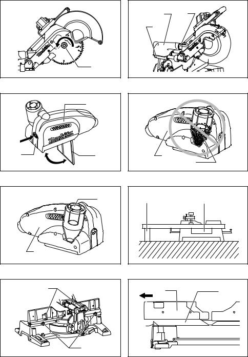
1.Press cutting (cutting small workpieces) (Fig. 42)
Workpieces up to 68 mm high and 160 mm wide can be cut in the following manner.
After turning the stopper lever clockwise and sliding the carriage to your desired position, push the carriage toward the guide fence fully and tighten the locking screw clockwise and pull the lock lever towards the front of the saw to secure the carriage. Secure the workpiece correctly with the proper type of vise or crown molding stoppers.
Switch on the tool without the blade making any contact and wait until the blade attains full speed before lowering. Then gently lower the handle to the fully lowered position to cut the workpiece. When the cut is completed, switch off the tool and WAIT UNTIL THE BLADE HAS COME TO A COMPLETE STOP before returning the blade to its fully elevated position.
WARNING:
•Firmly tighten the locking screw clockwise and pull the lock lever towards the front of the saw so that the carriage will not move during operation. Insufficient tightening of the locking screw may cause possible kickback which may result in serious personal injury.
2.Slide (push) cutting (cutting wide workpieces)
(Fig. 43 & 44)
Loosen the locking screw counterclockwise and also push forward the lock lever so that the carriage can slide freely. Secure the workpiece with the proper type of vise. Pull the carriage toward you fully. Switch on the tool without the blade making any contact and wait until the blade attains full speed. Press the handle down and PUSH THE CARRIAGE TOWARD THE GUIDE FENCE AND THROUGH THE WORKPIECE. When the cut is completed, switch off the tool and WAIT UNTIL THE BLADE HAS COME TO A COMPLETE STOP before returning the blade to its fully elevated position.
20
WARNING:
•Whenever performing a slide cut, first pull the carriage full towards you and press the handle all the way down, then push the carriage toward the guide fence. Never start the cut with the carriage not pulled fully toward you. If you perform the slide cut without the carriage pulled fully toward you unexpected kickback may occur and serious personal injury may result.
•Never attempt to perform a slide cut by pulling the carriage towards you. Pulling the carriage towards you while cutting may cause unexpected kickback resulting in possible serious personal injury.
•Never perform the slide cut with the handle locked in the lowered position.
•Never loosen the knob which secures the carriage while the blade is rotating. A loose carriage while cutting may cause unexpected kickback resulting in possible in serious personal injury.
3.Mitre cutting
Refer to the previously covered “Adjusting the miter angle”.
4.Bevel cut (Fig. 45)
Loosen the lever and tilt the saw blade to set the bevel angle (Refer to the previously covered “Adjusting the bevel angle”). Be sure to retighten the lever firmly to secure the selected bevel angle safely. Secure the workpiece with a vise. Make sure the carriage is pulled all the way back toward the operator. Switch on the tool without the blade making any contact and wait until the blade attains full speed. Then gently lower the handle to the fully lowered position while applying pressure in parallel with the blade and PUSH THE CARRIAGE TOWARD THE GUIDE FENCE TO CUT THE WORKPIECE. When the cut is completed, switch off the tool and WAIT UNTIL THE BLADE HAS COME TO A COMPLETE STOP before returning the blade to its fully elevated position.
WARNING:
•After setting the blade for a bevel cut, before operating the tool ensure that the carriage and blade will have free travel throughout the entire range of the intended cut. Interruption of the carriage or blade travel during the cutting operation may result in kickback and serious personal injury.
Measuring
•While making a bevel cut keep hands out of the path of the blade. The angle of the blade may confuse the operator as to the actual blade path while cutting and contact with the blade will result in serious personal injury.
•The blade should not be raised until it has come to a complete stop. During a bevel cut the piece cut off may come to rest against the blade. If the blade is raised while it is rotating the cut-off piece maybe ejected by the blade causing the material to fragment which may result in serious personal injury.
NOTICE:
•When pressing down the handle, apply pressure in parallel with the blade. If a force is applied perpendicularly to the turn base or if the pressure direction is changed during a cut, the precision of the cut will be impaired.
•Before bevel-cutting, an adjustment of the upper fence and lower fence maybe required. Refer to the section titled “Guide fence adjustment”.
5.Compound cutting
Compound cutting is the process in which a bevel angle is made at the same time in which a miter angle is being cut on a workpiece. Compound cutting can be performed at the angle shown in the table.
Miter angle |
Bevel angle |
|
|
Left and Right 0° – 45° |
Left and Right 0° – 45° |
|
|
When performing compound cutting, refer to “Press cutting”, “Slide cutting”, “Miter cutting” and “Bevel cut” explanations.
6.Cutting crown and cove moldings
Crown and cove moldings can be cut on a compound miter saw with the moldings laid flat on the turn base. There are two common types of crown moldings and one type of cove moldings; 52/38° wall angle crown molding, 45° wall angle crown molding and 45° wall angle cove molding. See illustrations. (Fig. 46)
There are crown and cove molding joints which are made to fit “Inside” 90° corners ((1) and (2) in Fig. 47 & 48) and “Outside” 90° corners ((3) and (4) in Fig. 47 & 48).
Measure the wall length and adjust workpiece on table to cut wall contact edge to desired length. Always make sure that cut workpiece length at the back of the workpiece is the same as wall length. Adjust cut length for angle of cut. Always use several pieces for test cuts to check the saw angles.
When cutting crown and cove moldings, set the bevel angle and miter angle as indicated in the table (A) and position the moldings on the top surface of the saw base as indicated in the table (B).
In the case of left bevel cut
Table (A)
|
Molding position |
Bevel angle |
Miter angle |
|||
|
|
|
|
|
||
|
in Fig. 47 & 48 |
52/38° type |
45° type |
52/38° type |
45° type |
|
|
|
|||||
|
|
|
|
|
|
|
For inside corner |
(1) |
|
|
Right 31.6° |
Right 35.3° |
|
|
|
|
|
|
||
(2) |
Left 33.9° |
Left 30° |
Left 31.6° |
Left 35.3° |
||
|
||||||
|
|
|||||
For outside corner |
(3) |
|||||
|
|
|
|
|||
|
|
|
|
|
||
(4) |
|
|
Right 31.6° |
Right 35.3° |
||
|
|
|
||||
|
|
|
|
|
|
|
21
Table (B)
|
Molding position |
Molding edge against guide fence |
Finished piece |
|
|
in Fig. 47 & 48 |
|||
|
|
|
||
|
|
|
|
|
|
(1) |
Ceiling contact edge should be |
Finished piece will be on the Left |
|
For inside corner |
against guide fence. |
|||
|
||||
|
|
side of blade. |
||
|
(2) |
Wall contact edge should be against |
||
|
|
|||
|
|
|
||
|
(3) |
guide fence. |
Finished piece will be on the Right |
|
|
|
|||
For outside corner |
|
|
||
|
Ceiling contact edge should be |
|||
(4) |
side of blade. |
|||
|
||||
|
against guide fence. |
|
||
|
|
|
||
|
|
|
|
Example:
In the case of cutting 52/38° type crown molding for position (1) in Fig. 47 & 48:
•Tilt and secure bevel angle setting to 33.9° LEFT.
•Adjust and secure miter angle setting to 31.6° RIGHT.
•Lay crown molding with its broad back (hidden) surface down on the turn base with its CEILING CONTACT EDGE against the guide fence on the saw.
•The finished piece to be used will always be on the LEFT side of the blade after the cut has been made.
In the case of right bevel cut
Table (A)
|
Molding position |
Bevel angle |
|
Miter angle |
||||
|
|
|
|
|
|
|
||
|
in Fig. 47 & 48 |
|
52/38° type |
|
45° type |
|
52/38° type |
45° type |
|
|
|
|
|
||||
|
|
|
|
|
|
|
|
|
For inside corner |
(1) |
|
|
|
|
|
Right 31.6° |
Right 35.3° |
|
|
|
|
|
|
|
|
|
(2) |
|
Right 33.9° |
|
Right 30° |
|
Left 31.6° |
Left 35.3° |
|
|
|
|
|
|||||
|
|
|
|
|
||||
For outside corner |
(3) |
|
|
|||||
|
|
|
|
|
|
|
||
|
|
|
|
|
|
|
|
|
(4) |
|
|
|
|
|
Right 31.6° |
Right 35.3° |
|
|
|
|
|
|
|
|||
|
|
|
|
|
|
|
|
|
Table (B) |
|
|
|
|
|
|
|
|
|
|
|
|
|
|
|
|
|
|
Molding position |
Molding edge against guide fence |
|
Finished piece |
||||
|
in Fig. 47 & 48 |
|
||||||
|
|
|
|
|
|
|
||
|
|
|
|
|
|
|
||
|
(1) |
|
Wall contact edge should be against |
|
Finished piece will be on the Right |
|||
For inside corner |
|
guide fence. |
|
|
||||
|
|
|
|
|||||
|
|
|
|
|
|
side of blade. |
|
|
|
(2) |
|
Ceiling contact edge should be |
|
|
|||
|
|
|
|
|
||||
|
|
|
|
|
|
|||
|
(3) |
|
against guide fence. |
|
|
Finished piece will be on the Left |
||
|
|
|
|
|
|
|||
For outside corner |
|
|
|
|
|
|
||
|
|
Wall contact edge should be against |
|
|||||
(4) |
|
|
side of blade. |
|
||||
|
|
|
|
|||||
|
|
guide fence. |
|
|
|
|
||
|
|
|
|
|
|
|
||
|
|
|
|
|
|
|
|
|
Example:
In the case of cutting 52/38° type crown molding for position (1) in Fig. 47 & 48:
•Tilt and secure bevel angle setting to 33.9° RIGHT.
•Adjust and secure miter angle setting to 31.6° RIGHT.
•Lay crown molding with its broad back (hidden) surface down on the turn base with its WALL CONTACT EDGE against the guide fence on the saw.
•The finished piece to be used will always be on the RIGHT side of the blade after the cut has been made.
Crown molding stoppers (optional accessories) allow easier cuts of crown molding without tilting the saw blade. Install them on the base as shown in the figures. (Fig. 49 & 50)
Fig. 49: At right 45° miter angle
Fig. 50: At left 45° miter angle
Position crown molding with its WALL CONTACT EDGE against the guide fence and its CEILING CONTACT EDGE against the crown molding stoppers as shown in the figure (Fig. 51). Adjust the crown molding stoppers according to the size of the crown molding. Tighten the screws to secure the crown molding stoppers. Refer to the table (C) for the miter angle.
22
Table (C)
|
Molding position |
Miter angle |
Finished piece |
|
|
in Fig. 47 & 48 |
|||
|
|
|
||
|
|
|
|
|
For inside corner |
(1) |
Right 45° |
Save the right side of blade |
|
|
|
|
||
(2) |
Left 45° |
Save the left side of blade |
||
|
||||
|
|
|
||
For outside corner |
(3) |
Save the right side of blade |
||
|
||||
|
|
|
||
(4) |
Right 45° |
Save the left side of blade |
||
|
||||
|
|
|
|
7.Cutting aluminum extrusion
When securing aluminum extrusions, use spacer blocks or pieces of scrap as shown in Fig. 52 to prevent deformation of the aluminum. Use a cutting lubricant when cutting the aluminum extrusion to prevent build-up of the aluminum material on the blade.
WARNING:
•Never attempt to cut thick or round aluminum extrusions. Thick or round aluminum extrusions can be difficult to secure and may work loose during the cutting operation which may result in loss of control and serious personal injury.
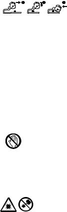
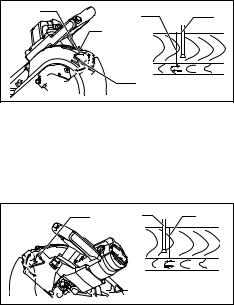
8.Groove cutting (Fig. 53)
A dado type cut can be made by proceeding as follows: Adjust the lower limit position of the blade using the adjusting screw and the stopper arm to limit the cutting depth of the blade. Refer to “Stopper arm” section described previously.
After adjusting the lower limit position of the blade, cut parallel grooves across the width of the workpiece using a slide (push) cut as shown in the figure. Then remove the workpiece material between the grooves with a chisel.
WARNING:
•Do not attempt to perform this type of cut by using a wider type blade or dado blade. Attempting to make a groove cut with a wider blade or dado blade could lead to unexpected cutting results and kickback which may result in serious personal injury.
•Be sure to return the stopper arm to the original position when performing other than groove cutting. Attempting to make cuts with the stopper arm in the incorrect position could lead to unexpected cutting results and kickback which may result in serious personal injury.
Carrying tool
Make sure that the tool is unplugged. Secure the blade at 0° bevel angle and the turn base at the full right miter angle position. Secure the slide poles so that the lower slide pole is locked in the position of the carriage fully pulled to operator and the upper poles are locked in the position of the carriage fully pushed forward to the guide fence (refer to the section titled “Slide lock adjustment”.) Lower the handle fully and lock it in the lowered position by pushing in the stopper pin. (Fig. 54)
Carry the tool by holding both sides of the tool base as shown in the figure. If you remove the holders, dust bag, etc., you can carry the tool more easily. (Fig. 55)
WARNING:
•Stopper pin is only for carrying and storage purposes and should never be used for any cutting operations. The use of the stopper pin for cutting operations may cause unexpected movement of the saw blade resulting in kickback and serious personal injury.
CAUTION:
•Always secure all moving portions before carrying the tool. If portions of the tool move or slide while being carried loss of control or balance may occur resulting in personal injury.
MAINTENANCE
WARNING:
•Always be sure that the tool is switched off and unplugged before attempting to perform inspection or maintenance. Failure to unplug and switch off the tool may result in accidental start up of the tool which may result in serious personal injury.
•Always be sure that the blade is sharp and clean for the best and safest performance. Attempting a cut with a dull and/or dirty blade may cause kickback and result in a serious personal injury.
NOTICE:
•Never use gasoline, benzine, thinner, alcohol or the like. Discoloration, deformation or cracks may result.
Adjusting the cutting angle
This tool is carefully adjusted and aligned at the factory, but rough handling may have affected the alignment. If your tool is not aligned properly, perform the following:
1.Miter angle
Push the carriage toward the guide fence and tighten the locking screw clockwise and pull the lock lever towards the front of the saw to secure the carriage.
Turn the grip counterclockwise which secures the turn base. Turn the turn base so that the pointer points to 0° on the miter scale. Then turn the turn base slightly clockwise and counterclockwise to seat the turn base in the 0° miter notch. (Leave as it is if the pointer does not point to 0°.) Loosen the hex socket bolts securing the guide fence using the socket wrench.
Lower the handle fully and lock it in the lowered position by pushing in the stopper pin. Square the side of the blade with the face of the guide fence using a triangular rule, try-square, etc. Then securely tighten the hex socket bolts on the guide fence in order starting from the right side. (Fig. 56)
Make sure that the pointer points to 0° on the miter scale. If the pointer does not point to 0°, loosen the screw which secures the pointer and adjust the pointer so that it will point to 0°. (Fig. 57)
23
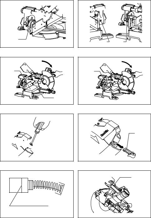
2.Bevel angle
Push the latch lever forward fully to release the positive stops.
1)0° bevel angle
Push the carriage toward the guide fence and tighten the locking screw clockwise and pull the lock lever towards the front of the saw to secure the carriage. Lower the handle fully and lock it in the lowered position by pushing in the stopper pin. Loosen the lever at the rear of the tool. (Fig. 58)
Turn the hex socket bolt on the right side of the arm holder two or three revolutions counterclockwise to tilt the blade to the right. (Fig. 59)
Carefully square the side of the blade with the top surface of the turn base using the triangular rule, trysquare, etc. by turning the hex socket bolt on the right side of the arm holder clockwise. Then tighten the lever securely. (Fig. 60)
Make sure that the pointers on the arm holder point to each 0° on the bevel scale on the arm. If they do not point to 0°, loosen the screws which secure the pointers and adjust them so that they will point to 0°.
(Fig. 61)
2)45° bevel angle (Fig. 62)
Adjust the 45° bevel angle only after performing 0° bevel angle adjustment. To adjust left 45° bevel angle, loosen the lever and tilt the blade to the left fully. Make sure that the pointer on the arm holder points to 45° on the bevel scale on the arm. If the pointer does not point to 45°, turn the left 45° bevel angle adjusting bolt on the side of the arm until the pointer points to 45°.
To adjust right 45° bevel angle, perform the same procedure described above.
Adjustment of the laser line position (Fig. 63 & 64)
For models LS1016L and LS1016FL only
WARNING:
•Since the tool must be plugged in while adjusting the laser line, special care must be taken to not switch on the tool. Accidental start up of the tool may result in serious personal injury.
CAUTION:
•Never look directly into the laser beam. Direct eye exposure to the beam could cause serious damage to the eyes.
•LASER RADIATION Do not stare into beam.
NOTICE:
•Beware that impacts to the tool may cause the laser line to be misaligned or may cause damage to the laser, shortening its life.
Adjusting the laser line for the left side of the blade.
1 |
4 |
5 |
|
||
|
2 |
|
|
|
3 |
1Screw to change the movable range of the adjusting screw
2Adjusting screw
3Hex wrench
4Laser line
5Saw blade
Adjusting the laser line for the right side of the blade.
1 |
2 |
3 |
1Adjusting screw
2Saw blade
3Laser line
For both adjustments, do as follows.
1.Make sure that the tool is unplugged.
2.Draw the cutting line on the workpiece and place it on the turn table. At this time, do not secure the workpiece with a vise or similar securing device.
3.Lower the blade by lowering the handle and just check to see where the cutting line and the position of the saw blade is. (Decide which position to cut on the line of cut.)
4.After deciding the correct position of the line in relation to the blade, return the handle to the original position. Secure the workpiece with the vertical vise without shifting the workpiece from the pre-checked position.
5.Plug the tool and turn on the laser switch.
6.Adjust the position of laser line as follows.
The position of laser line can be changed as the movable range of the adjusting screw for the laser is changed by turning two screws with a hex wrench. (The movable range of laser line is factory adjusted within 1 mm from the side surface of blade.)
24
To shift the laser line movable range further away from the side surface of blade, turn the two screws counterclockwise after loosening the adjusting screw. Turn these two screws clockwise to shift it closer to the side surface of the blade after loosening the adjusting screw.
Refer to the section titled “Laser beam action” and adjust the adjusting screw so that the cutting line on your workpiece is aligned with the laser line.
NOTE:
•Check the position of laser line regularly for accuracy.
•Have the tool repaired by a Makita authorized service center for any failure on the laser unit.
Cleaning the laser light lens (Fig. 65 & 66)
For models LS1016L and LS1016FL only
If the lens for the laser light becomes dirty, or sawdust adheres to it in such a way that the laser line is no longer easily visible, unplug the saw and remove and clean the lens for the laser light carefully with a damp, soft cloth. Do not use solvents or any petroleum-based cleaners on the lens.
To remove the lens for the laser light, remove the saw blade before removing the lens according to the instructions in the section titled “Installing or removing saw blade”.
Loosen but do not remove the screw which secures the lens using a screwdriver.
Pull out the lens as shown in the figure.
NOTE:
•If the lens does not come out, loosen the screw further and pull out the lens again without removing the screw.
Replacing carbon brushes (Fig. 67 & 68)
Remove and check the carbon brushes regularly. Replace when they wear down to the limit mark. Keep the carbon brushes clean and free to slip in the holders. Both carbon brushes should be replaced at the same time. Use only identical carbon brushes.
Use a screwdriver to remove the brush holder caps. Take out the worn carbon brushes, insert the new ones and secure the brush holder caps.
After replacing brushes, plug in the tool and break in brushes by running tool with no load for about 10 minutes. Then check the tool while running and electric brake operation when releasing the switch trigger. If the electric brake is not working correctly, have the tool repaired by a Makita service center.
After use
•After use, wipe off chips and dust adhering to the tool with a cloth or the like. Keep the blade guard clean according to the directions in the previously covered section titled “Blade guard”. Lubricate the sliding portions with machine oil to prevent rust.
•When storing the tool, pull the carriage toward you fully so that the slide pole is thoroughly inserted into the turn base.
To maintain product SAFETY and RELIABILITY, repairs, any other maintenance or adjustment should be performed by Makita Authorized Service Centers, always using Makita replacement parts.
ACCESSORIES
WARNING:
•These accessories or attachments are recommended for use with your Makita tool specified in this manual. The use of any other accessories or attachments may result in serious personal injury.
•Only use the Makita accessory or attachment for its stated purpose. Misuse of an accessory or attachment may result in serious personal injury.
If you need any assistance for more details regarding these accessories, ask your local Makita Service Center.
• Steel & Carbide-tipped saw blades
Miter saw blades |
For smooth and precise cutting in |
|
various materials. |
||
|
||
|
|
|
|
General purpose blade for fast |
|
Combination |
and smooth rip, crosscuts and |
|
|
miters. |
|
|
|
|
Crosscutting |
For smoother cross grain cuts. |
|
Slices cleanly against the grain. |
||
|
||
|
|
|
Fine cross cuts |
For sand-free cuts cleanly against |
|
the grain. |
||
|
||
|
|
|
Non-ferrous metals |
For miters in aluminum, copper, |
|
miter saw blades |
brass, tubing, and other non-fer- |
|
rous metals. |
||
|
||
|
|
•Vise assembly (Horizontal vise)
•Vertical vise
•Socket wrench 13
•Holder
•Dust bag
•Crown molding stopper set
•Triangular rule
•Dust box
•Hex wrench (For LS1016L and LS1016FL)
25

FRANÇAIS (Instructions originales)
Descriptif
1 |
Broche d’arrêt |
35 |
Blocage de l’arbre |
67 |
Butée de moulure couronnée de |
2 |
Boulon(s) hexagonal(aux) |
36 |
Carter de lame |
|
droite (Accessoire en option) |
3 |
Protecteur de lame |
37 |
Flèche |
68 |
Butée de moulure couronnée de |
4 |
Plateau de découpe |
38 |
Flasque extérieur |
|
gauche |
5 |
Lame de scie |
39 |
Flasque intérieur |
69 |
Butée de moulure couronnée de |
6 |
Dents de lame |
40 |
Axe |
|
droite |
7 |
Coupe en biseau à gauche |
41 |
Bague |
70 |
Moulure couronnée |
8 |
Coupe droite |
42 |
Raccord à poussières |
71 |
Étau |
9 |
Coupe en biseau à droite |
43 |
Sac à poussière |
72 |
Cale d’écartement |
10 |
Levier de verrouillage |
44 |
Fermeture |
73 |
Profilé d’aluminium |
11 |
Vis |
45 |
Boîte à poussières |
74 |
Coupe de rainures avec la lame |
12 |
Boulon de réglage |
46 |
Couvercle |
75 |
Règle triangulaire |
13 |
Plateau tournant |
47 |
Bouton |
76 |
Secteur |
14 |
Levier de butée |
48 |
Section cylindrique |
77 |
Plaque graduée de coupe en |
15 |
Tuyau de glissement |
49 |
Sciure de bois |
|
biseau |
16 |
Face supérieure du plateau |
50 |
Cale |
78 |
Boulon de réglage d’angle 0° |
|
tournant |
51 |
Plateau tournant |
79 |
Secteur angulaire |
17 |
Périphérie de la lame |
52 |
Vis de serrage |
80 |
Boulon de réglage de l’angle |
18 |
Guide |
53 |
Guide supérieur |
|
de biseau de 45° à gauche |
19 |
Vis de réglage |
54 |
Guide inférieur |
81 |
Boulon de réglage de l’angle |
20 |
Bras de blocage |
55 |
Poignée de l’étau |
|
de biseau de 45° à droite |
21 |
Poignée |
56 |
Bras de l’étau |
82 |
Pièce à travailler |
22 |
Came |
57 |
Tige de l’étau |
83 |
Ligne laser |
23 |
Levier(s) |
58 |
Plaque d’étau |
84 |
Étau vertical |
24 |
Levier de fermeture |
59 |
Ecrou de l’étau |
85 |
Tournevis |
25 |
Secteur angulaire |
60 |
Servante |
86 |
Vis (une pièce seulement) |
26 |
Bouton de libération |
61 |
Moulure couronnée du type |
87 |
Lentille du laser |
27 |
Index |
|
52/38° |
88 |
Repère d’usure |
28 |
Bouton de déverrouillage |
62 |
Moulure couronnée du type 45° |
89 |
Bouchon de porte-charbon |
29 |
Gâchette |
63 |
Moulure concave du type 45° |
90 |
Vis de verrouillage |
30 |
Orifice pour cadenas |
64 |
Coin intérieur |
91 |
Interrupteur de lampe |
31 |
Interrupteur du laser |
65 |
Coin extérieur |
92 |
Lampe |
32 |
Clé à douille |
66 |
Butée de moulure couronnée de |
93 |
Zone d’indication rouge |
33 |
Support à clé |
|
gauche (Accessoire en option) |
|
|
34 |
Capot central |
|
|
|
|
|
|
|
|
|
|
SPECIFICATIONS |
|
|
|
|
|
Modèle |
|
|
LS1016/LS1016L/LS1016F/LS1016FL |
||
Diamètre de la lame |
|
|
|
|
|
Pour tous les pays à l’exception de l’Europe .................................................................................. |
|
255 mm et 260 mm |
|||
Pour l’Europe.................................................................................................................................................... |
|
|
|
260 mm |
|
Diamètre de l’orifice |
|
|
|
|
|
Pour tous les pays à l’exception de l’Europe ................................................................................................... |
|
25,4 mm |
|||
Pour l’Europe...................................................................................................................................................... |
|
|
|
30 mm |
|
Capacités de coupe maximales (H x P) avec une lame d’un diamètre de 260 mm
Angle d’onglet |
|
Angle de biseau |
|
|
|
|
|
||
|
45° (gauche) |
0° |
45° (droite) |
|
|
|
|
|
|
0° |
42 mm x 310 mm |
68 mm x 310 mm |
29 mm x 310 mm |
|
|
|
|
||
58 mm x 279 mm |
91 mm x 279 mm |
43 mm x 279 mm |
||
|
||||
|
|
|
|
|
45° (droite et gauche) |
42 mm x 218 mm |
68 mm x 218 mm |
29 mm x 218 mm |
|
|
|
|
||
58 mm x 197 mm |
91 mm x 197 mm |
43 mm x 197 mm |
||
|
||||
|
|
|
|
|
52° (droite et gauche) |
– |
68 mm x 190 mm |
– |
|
|
||||
91 mm x 171 mm |
||||
|
|
|
||
|
|
|
|
|
60° (droite) |
– |
68 mm x 155 mm |
– |
|
|
||||
91 mm x 139 mm |
||||
|
|
|
||
|
|
|
|
26

Capacités de coupe maximales en position de coupe spéciale
Moulure couronnée du type 45° |
168 mm |
|
(avec butée de moulure couronnée utilisée) |
||
|
||
|
|
|
Plinthe (H) (avec étau horizontal utilisé) |
120 mm |
|
|
|
|
Vitesse à vide (min–1).............................................................................................................................................. |
3 200 |
|
Type de laser (LS1016L, LS1016FL).............................................. |
Laser rouge 650 nm, <1,6mW (Laser de classe 2M) |
|
Dimensions (L x l x H) ........................................................................................................ |
718 mm x 640 mm x 671 mm |
|
Poids net |
|
|
Pour tous les pays à l’exception de l’Europe |
|
|
LS1016 .............................................................................................................................................................. |
23,6 kg |
|
LS1016L/LS1016F............................................................................................................................................. |
23,7 kg |
|
LS1016FL .......................................................................................................................................................... |
23,8 kg |
|
Pour l’Europe |
|
|
LS1016 .............................................................................................................................................................. |
24,1 kg |
|
LS1016L/LS1016F............................................................................................................................................. |
24,2 kg |
|
LS1016FL .......................................................................................................................................................... |
24,3 kg |
|
Niveau de sécurité................................................................................................................................................... |
/II |
|
|
|
•Etant donné l’évolution constante de notre programme de recherche et de développement, les spécifications contenues dans ce manuel sont sujettes à modification sans préavis.
•Les spécifications peuvent varier suivant les pays.
•Poids selon la procédure EPTA 01/2003
Utilisations
L’outil est conçu pour effectuer des coupes de bois rectilignes et des coupes d’onglet, avec précision. Avec des lames appropriées, il permet également de couper l’aluminium.
Alimentation
L’outil ne devra être raccordé qu’à une alimentation de la même tension que celle qui figure sur la plaque signalétique, et il ne pourra fonctionner que sur un courant secteur monophasé. Réalisé avec une double isolation, il est conforme à la réglementation européenne et peut de ce fait être alimenté sans mise à la terre.
GEA010-1
Consignes de sécurité générales pour outils électriques
 MISE EN GARDE Veuillez lire toutes les mises en garde et toutes les instructions. Il y a risque de choc électrique, d’incendie et/ou de blessure grave si les mises en garde et les instructions ne sont pas respectées.
Conservez toutes les mises en garde et instructions pour référence ultérieure.
ENB034-6
PRECAUTIONS SUPPLEMENTAIRES POUR L’OUTIL
1.Portez une protection oculaire.
2.Gardez bien les mains à l’écart de la lame. Évitez tout contact avec une lame “en roue libre”. Vous pourriez vous blesser gravement.
3.N’utilisez jamais la scie sans les protections en place.
Vérifiez le bon fonctionnement du protecteur de lame avant chaque utilisation. N’utilisez pas la scie si le protecteur de lame ne se déplace pas librement et ne recouvre pas la lame instantanément. N’immobilisez jamais le protecteur de lame en position ouverte.
4.Ne sciez jamais à la volée. Le matériau doit être assuré fermement contre le plateau tournant et le guide au moyen de l’étau durant tous les types de sciage. Ne maintenez jamais la pièce avec la main.
5.Gardez bien les mains à l’écart de la lame.
6.Coupez le contact et attendez l’arrêt de la lame avant de déplacer la pièce ou de modifier les réglages.
7.Débranchez l’outil avant de procéder à un changement de lame ou à une réparation.
8.Avant de transporter l’outil, immobilisez d’abord toutes ses pièces mobiles.
9.La broche d’arrêt qui verrouille en position basse la tête de fraisage sert à des fins de transport et de rangement uniquement et pas pour les opérations de coupe.
10.Ne vous servez pas de votre outil en présence de gaz ou de liquides inflammables. L’utilisation de cet outil électrique comporte un risque d’explosion et d’incendie en présence de liquides ou gaz inflammables.
11.Avant de scier, vérifiez attentivement que la lame n’est ni endommagée, ni fendue.
Si tel est le cas, changez-la immédiatement.
12.N’utilisez que les flasques spécifiés pour cet outil.
13.Prenez garde d’endommager l’alésage, les flasques (tout particulièrement leur surface d’installation) ou le boulon. L’endommagement de ces pièces peut causer une cassure de la lame.
14.Assurez-vous que le plateau tournant est bien immobilisé, afin qu’il ne risque pas de se déplacer pendant le sciage.
15.Pour votre sécurité, retirez copeaux ou autres fragments de la surface du plateau avant la mise en route.
16.Évitez les clous. Avant de travailler votre pièce, inspectez-la et retirez-en tous les clous.
17.Assurez-vous que le blocage de l’arbre est relâché avant de mettre le contact.
18.Assurez-vous que la lame ne touche pas le plateau tournant quand elle est abaissée au maximum.
19.Tenez la poignée fermement. N’oubliez pas que la scie se déplace légèrement de haut en bas au démarrage et à l’arrêt.
27
20.Assurez-vous que la lame ne touche pas la pièce
àscier avant de mettre le contact.
21.Avant de scier la pièce, faites tourner l’outil un instant à vide. Vérifiez que la lame ne présente ni balourd ni shimmy qui pourraient résulter d’un montage incorrect ou d’une usure irrégulière.
22.Avant de scier, attendez que la lame ait atteint sa pleine vitesse.
23.Arrêtez immédiatement le sciage si vous remarquez quoi que ce soit d’anormal.
24.Ne tentez pas de maintenir la gâchette en position ON.
25.Restez vigilant, surtout durant les sciages répétés et monotones. Ne vous laissez jamais prendre par un sentiment trompeur de sécurité. Les lames de scie ne pardonnent pas.
26.N’utilisez que les accessoires recommandés dans ce manuel. L’utilisation d’accessoires différents, disques à tronçonner notamment, peut entraîner une blessure.
27.N’utilisez pas la scie pour couper autre chose que de l’aluminium, du bois ou des matériaux similaires.
28.Raccordez les scies à coupe d’onglet à un dispositif de ramassage de la poussière quand vous effectuez un sciage.
29.Sélectionnez les lames en fonction du matériau
àcouper.
30.Faites attention lorsque vous taillez des encoches.
31.Remplacez le plateau de découpe quand il est usé.
32.Ne pas utiliser de lames fabriquées en acier à coupe rapide.
33.Les poussières dégagées lors de l’utilisation de l’outil peuvent contenir certains produits chimiques reconnus comme pouvant causer le cancer, des anomalies congénitales ou autres problèmes de reproduction. Parmi ces produits chimiques figurent notamment :
• le plomb que contient les matériaux recouverts de peinture à base de plomb ;
• l’arsenic et le chrome que contient le bois de construction traité chimiquement.
Les risques encourus varient suivant la fréquence d’exposition qu’implique votre travail. Pour réduire votre degré d’exposition à ces produits chimiques : travaillez dans une aire de travail bien aérée et en utilisant des dispositifs de sécurité approuvés, tels que des masques à poussière spécialement conçus pour filtrer les particules microscopiques.
34.Pour réduire le bruit émis par la lame, assurezvous toujours qu’elle est bien affûtée et propre.
35.L’utilisateur doit avoir reçu une formation adéquate concernant l’utilisation, le réglage et le fonctionnement de l’outil.
36.Utilisez des lames bien affûtées. Respectez la vitesse maximale indiquée sur la lame.
37.Évitez de retirer de la zone de coupe les coupures et autres bouts détachés de la pièce à couper pendant que l’outil tourne encore et que la tête de la lame n’est pas en position de repos.
38.Utilisez exclusivement les lames recommandées par le fabricant et conformes à la norme EN847-1.
39.Portez des gants pour manipuler la lame (les lames doivent être transportées dans un étui lorsque possible) et les pièces de matériau rude.
40.Lors de l’utilisation avec un laser, ne remplacez pas un type de laser différent. Toute réparation doit être effectuée de manière adéquate.
CONSERVEZ CES INSTRUCTIONS
INSTALLATION
Montage du banc
À sa sortie d’usine, la poignée de cet outil est verrouillé en position abaissée par la broche d’arrêt. Libérez la broche d’arrêt en appliquant une légère pression vers le bas sur la poignée tout en tirant sur la broche d’arrêt. (Fig. 1)
AVERTISSEMENT :
•Assurez-vous que l’outil ne bougera pas sur la surface de soutien. Si la scie à onglet bouge sur la surface de soutien pendant la coupe, il y a risque de perte de contrôle et de blessure grave.
Boulonnez l’outil à l’aide de quatre boulons sur une surface stable et de niveau en utilisant les orifices de boulon prévus sur le socle de l’outil. Ceci pour empêcher tout risque de renversement et de blessure. (Fig. 2)
DESCRIPTION DU FONCTIONNEMENT
AVERTISSEMENT :
•Vérifiez que l’outil est hors tension et débranché avant de l’ajuster ou de vérifier son fonctionnement. Il y a risque de démarrage accidentel et de blessure grave si vous ne coupez pas le contact et ne débranchez pas l’outil.
Protecteur de lame (Fig. 3 et 4)
Le protecteur de lame s’élève automatiquement lorsque vous abaissez la poignée. Le protecteur revient à sa position d’origine une fois la coupe terminée et la poignée relevé.
AVERTISSEMENT :
•Ne jamais modifier ou retirer le protecteur de lame ou son ressort. Une lame exposée suite à la modification du protecteur peut entraîner une blessure grave lors de l’utilisation.
Pour votre propre sécurité, maintenez toujours le protecteur de lame en bonne condition. Tout fonctionnement irrégulier du protecteur de lame doit être corrigé immédiatement. Vérifiez que le mécanisme de rappel du protecteur fonctionne correctement.
AVERTISSEMENT :
•Ne jamais utiliser l’outil si le protecteur de lame ou le ressort est endommagé, défectueux ou retiré.
L’utilisation de l’outil avec un protecteur endommagé, défectueux ou retiré peut entraîner une blessure grave.
Si le protecteur de lame transparent devient sale ou si la sciure de bois y adhère au point que la lame et/ou la pièce ne soit plus bien visible, débranchez la scie et nettoyez soigneusement le protecteur avec un chiffon humide. N’utilisez aucun solvant ou nettoyant à base de pétrole sur le protecteur de plastique, car cela risquerait de l’abîmer.
Si le protecteur de lame est sale et doit être nettoyé pour assurer un fonctionnement adéquat, suivez les étapes cidessous :
28
Avec l’outil hors tension et débranché, utilisez la clé à douille fournie pour desserrer le boulon hexagonal qui retient le capot central. Desserrez le boulon hexagonal en le faisant tourner vers la gauche, puis soulevez le protecteur de lame et le capot central.
Le nettoyage du protecteur de lame peut être effectué de manière plus complète et efficace lorsqu’il se trouve dans cette position. Une fois le nettoyage terminé, effectuez la procédure ci-dessus en sens inverse et fixez le boulon. Ne retirez pas le ressort du protecteur de lame. Si le protecteur se détériore avec le temps ou sous l’effet des rayons ultraviolets, contactez un Centre d’Entretien Makita pour vous procurer un nouveau protecteur.
NE PAS MODIFIER OU RETIRER LE PROTECTEUR.
Positionnement du plateau de découpe (Fig. 5, 6 et 7)
Le socle rotatif de cet outil est équipé de plateaux de découpe pour minimiser la déchirure du côté de sortie de la coupe. Les plateaux de découpe sont réglés en usine de sorte qu’ils n’entrent pas en contact avec la lame. Avant l’utilisation, ajustez les plateaux de découpe comme suit :
Débranchez d’abord l’outil. Desserrez toutes les vis qui retiennent les plateaux de découpe (2 à droite et 2 à gauche). Ne les resserrez que partiellement, de sorte qu’il soit facile de déplacer manuellement les plateaux de découpe. Abaissez complètement la poignée et enfoncez la broche d’arrêt pour verrouiller la poignée en position abaissée. En tournant dans le sens contraire des aiguilles d’une montre, desserrez la vis de verrouillage qui retient les tiges de glissement supérieures, et poussez vers l’avant le levier de verrouillage qui retient les tiges de glissement inférieures. Tirez complètement le chariot vers vous. Ajustez les plateaux de découpe de sorte qu’ils touchent très légèrement les côtés des dents de la lame. Serrez légèrement les vis à l’avant. Poussez complètement le chariot vers le guide et ajustez les plateaux de découpe de sorte qu’ils touchent très légèrement les côtés des dents de la lame. Serrez légèrement les vis à l’arrière.
Après avoir ajusté les plateaux de découpe, dégagez la broche d’arrêt et levez la poignée. Serrez ensuite toutes les vis fermement.
REMARQUE :
•Après avoir réglé l’angle de coupe en biseau, assu- rez-vous que les plateaux de découpe sont bien ajustés. Des plateaux de découpe bien ajustés contribuent au soutien adéquat de la pièce et réduisent l’effet d’arrachement sur la pièce.
Maintien de la capacité de coupe maximale (Fig. 8, 9 et 10)
Cet outil est réglé en usine pour offrir une capacité de coupe maximale avec une lame de 260 mm. Débranchez l’outil avant de tenter tout réglage.
Lorsque vous installez une nouvelle lame, vérifiez toujours la position limite inférieure de la lame, et réglez-la comme suit si nécessaire :
Débranchez d’abord l’outil. Abaissez le levier de butée pour placer la lame tel qu’indiqué sur l’illustration. Repoussez le chariot à fond vers la butée et abaissez complètement la poignée. Utilisez la clé à douille pour tourner le boulon de réglage jusqu’à ce que la périphérie de la lame se trouve légèrement sous la face supérieure du plateau tournant, au point de rencontre entre la face avant du guide et la face supérieure du plateau tournant. Débranchez l’outil et faites tourner la lame manuellement en maintenant la poignée en position complètement abaissée, afin d’être certain que la lame n’entre en contact avec aucune partie du plateau inférieur. Réajustez légèrement au besoin.
Après le réglage, pensez à remettre le levier de butée en position initiale en le tournant dans le sens contraire des aiguilles d’une montre.
AVERTISSEMENT :
•Après avoir installé une nouvelle lame sur l’outil débranché, assurez-vous toujours que la lame ne touche aucune partie du plateau inférieur lorsque la poignée est complètement abaissée. Si la lame entre en contact avec le plateau, elle risquera de causer un choc en retour et d’entraîner une blessure grave.
Bras de blocage (Fig. 11)
Le bras de blocage permet un réglage facile de la position limite inférieure de la lame. Pour l’ajuster, tournez le bras de blocage dans le sens de la flèche, tel qu’indiqué sur la figure. Ajustez la vis de réglage de sorte que la lame s’arrête à la position désirée lorsque la poignée est complètement abaissée.
Réglage de l’angle de coupe d’onglet (Fig. 12)
Poussez la poignée pour engager les cames, et tournezla dans le sens des aiguilles d’une montre jusqu’à ce qu’elle s’arrête. Tournez le plateau tournant tout en appuyant vers le bas sur le levier de verrouillage. Après avoir déplacé la poignée de sorte que l’index pointe sur l’angle désiré sur le secteur, tournez la poignée de 90° dans le sens contraire des aiguilles d’une montre pour verrouiller le plateau tournant.
ATTENTION :
•Après avoir modifié l’angle de coupe d’onglet, fixez toujours le plateau tournant en tournant la poignée de 90° dans le sens contraire des aiguilles d’une montre.
REMARQUE :
•Lorsque vous tournez le plateau tournant, veillez à bien relever la poignée à fond.
Réglage de l’angle de coupe en biseau (Fig. 13, 14 et 15)
Pour ajuster l’angle de coupe en biseau, desserrez le levier à l’arrière de l’outil en le tournant vers la gauche. Poussez le levier de fermeture complètement vers l’avant, tel qu’illustré, tout en soutenant le poids de la tête de la lame de façon à libérer la pression sur la broche de verrouillage.
Pour incliner le chariot vers la droite, inclinez-le d’abord légèrement vers la gauche après avoir desserré le levier et appuyez sur le bouton de libération. Tout en continuant d’appuyer sur le bouton de libération, inclinez le chariot vers la droite.
Inclinez la lame jusqu’à ce que l’index indique l’angle désiré sur l’échelle. Resserrez ensuite le levier à fond en le tournant vers la droite pour fixer le bras.
29
En tirant le levier de fermeture vers l’avant de la scie, vous pouvez verrouiller la lame à l’aide des butées fixes, sur un angle de 22,5 ° ou 33,9 ° par rapport à la surface du socle, à gauche comme à droite.
En poussant le levier de fermeture vers l’arrière de la scie tel qu’illustré, vous pouvez verrouiller la lame sur l’angle désirée à l’intérieur de la plage d’angle de biseau spécifiée.
ATTENTION :
•Après avoir modifié l’angle de coupe en biseau, fixez toujours le bras en tournant le levier vers la droite pour le serrer.
REMARQUE :
•Quand vous inclinez la lame, assurez-vous que la poignée est complètement relevée.
•Lorsque vous modifiez l’angle de coupe en biseau, assurez-vous toujours de bien placer les plateaux de découpe, tel que décrit dans la section “Positionnement du plateau de découpe”.
Réglage du verrou de glissement (Fig. 16)
Pour verrouiller la tige de glissement inférieure, tirez le levier de verrouillage vers l’avant de la scie.
Pour verrouiller la tige de glissement supérieure, tournez la vis de verrouillage dans le sens des aiguilles d’une montre.
Interrupteur
Pour l’Europe (Fig. 17)
Pour éviter tout déclenchement accidentel de la gâchette, l’outil est muni d’un bouton de déverrouillage. Pour démarrer l’outil, déplacez le levier sur la gauche, appuyez sur le bouton de déverrouillage et tirez sur la gâchette. Pour arrêter l’outil, relâchez la gâchette.
AVERTISSEMENT :
•Avant de brancher l’outil, assurez-vous toujours que la gâchette fonctionne correctement et qu’elle revient en position “OFF” une fois relâchée. Évitez de tirer sur la gâchette avec force lorsque le bouton de sécurité n’est pas enfoncé. Vous risqueriez de briser la gâchette. L’utilisation d’un outil dont la gâchette est défectueuse comporte un risque de perte de contrôle et de blessure grave.
Un orifice a été prévu sur la gâchette, ce qui permet de verrouiller l’outil avec un cadenas.
Pour tous les pays à l’exception de l’Europe (Fig. 18)
Pour éviter tout déclenchement accidentel de la gâchette, l’outil est muni d’un bouton de déverrouillage. Pour faire démarrer l’outil, appuyez sur le bouton de déverrouillage puis tirez sur la gâchette.
AVERTISSEMENT :
•Avant de brancher l’outil, assurez-vous toujours que la gâchette fonctionne correctement et qu’elle revient en position “OFF” une fois relâchée. Evitez de tirer sur la gâchette avec force lorsque le bouton de sécurité n’est pas enfoncé. Vous risqueriez de briser la gâchette. L’utilisation d’un outil dont la gâchette est défectueuse comporte un risque de perte de contrôle et de blessure grave.
Un orifice a été prévu sur la gâchette, ce qui permet de verrouiller l’outil avec un cadenas.
AVERTISSEMENT :
•N’utilisez pas un cadenas dont la tige ou le câble a un diamètre inférieur à 6,35 mm. Une tige ou un câble plus mince risquerait de ne pas verrouiller correctement l’outil en positon d’arrêt, ce qui comporte un risque d’activation accidentelle pouvant entraîner une blessure grave.
•NE JAMAIS utiliser un outil dont le fonctionnement de la gâchette est défectueux. Tout outil dont la gâchette est défectueuse est EXTRÊMEMENT DANGEREUX et doit être réparé avant toute nouvelle utilisation, autrement il y a risque de blessure grave.
•Pour assurer votre sécurité, cet outil est équipé d’un bouton de déverrouillage qui empêche de faire démarrer l’outil par inadvertance. NE JAMAIS utiliser l’outil s’il se met en marche lorsque vous tirez simplement sur la gâchette sans avoir appuyé sur le bouton de déverrouillage. Une gâchette non réparée comporte un risque d’activation accidentelle pouvant entraîner une blessure grave. Retournez alors l’outil à un Centre d’Entretien Makita pour le faire réparer AVANT de poursuivre l’utilisation.
•NE JAMAIS bloquer le bouton de déverrouillage avec du ruban ou de toute autre manière. Une gâchette dont le bouton de déverrouillage est bloqué comporte un risque d’activation accidentelle pouvant entraîner une blessure grave.
Allumage de la lampe (Fig. 19)
Pour les modèles LS1016F et LS1016FL uniquement
ATTENTION :
•Cette lampe n’est pas étanche à la pluie. Ne nettoyez pas la lampe avec de l’eau et évitez de l’utiliser sous la pluie ou dans un endroit humide. Cela risquerait de causer un choc électrique entraînant des émanations de fumée.
•Ne touchez pas la lentille de la lampe alors que cette dernière est allumée ou vient tout juste d’être éteinte et est encore très chaude. Il y a risque de brûlure.
•Évitez de heurter la lampe, afin de ne pas l’endommager ou raccourcir sa durée de service.
•Évitez de diriger directement le faisceau de lumière vers vos yeux. Il y a risque de blessure oculaire.
•Ne recouvrez pas la lampe avec un chiffon, du carton, une boîte ou tout autre objet similaire pendant qu’elle est allumée, pour éviter tout risque d’incendie ou de feu.
Pour allumer la lampe, appuyez sur la position supérieure (I) de l’interrupteur. Pour éteindre la lampe, appuyez sur la position inférieure (O) de l’interrupteur.
Déplacez la lampe pour éclairer une autre zone.
NOTE :
•Utilisez un chiffon sec pour essuyer les saletés qui recouvrent la lentille de la lampe. Prenez garde de rayer la lentille de la lampe, sinon sa capacité d’éclairage sera affectée.
Fonction électronique
Commande de vitesse constante
•L’outil est doté d’une fonction de commande électronique de la vitesse qui aide à maintenir une vitesse de rotation constante de la lame même sous une lourde charge. Une vitesse de rotation constante de la lame permet d’effectuer la coupe de manière très fluide.
30
 Loading...