

Page 1

r
C
M150 & M200
Self-Propelled Windrowe
OPERATOR’S MANUAL
Revision
Part #169017 $25
Page 2
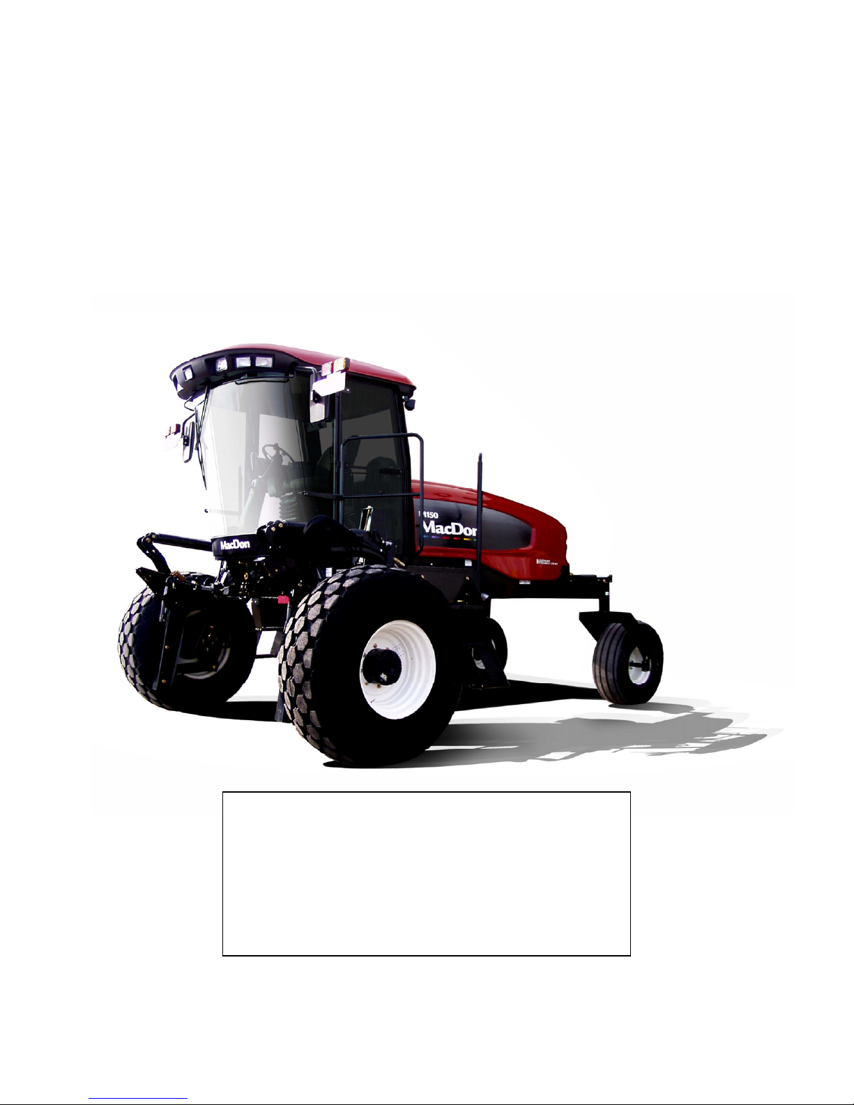
This Manual contains instructions for “SAFETY”, “OPERATION”, and “MAINTENANCE/SERVICE” for your new MacDon
Model M150 and M200 Self-Propelled Windrower.
Diesel engine exhaust and some of its constituents are known
to the State of California to cause cancer, birth defects, and
other reproductive harm.
Battery posts, terminals and related accessories contain lead
and lead components.
CALIFORNIA
Proposition 65 Warning
Wash hands after handling.
Page 3
1 INTRODUCTION
This instructional manual contains information on the MacDon Model M150 and M200 Self-Propelled Windrowers that
are designed to cut and lay in windrows, a wide variety of grain, hay and specialty crops. Windrowing allows starting
the harvest earlier, protects the crop from wind damage, and gives you more fle x ibility in scheduling combine time.
The power unit (referred to in this manual as the “Windrower”), when coupled with one of the specially designed
auger, rotary, or draper headers, provides a package which incorporates many features and improvements in design.
This manual must be used in conjunction with your Header Operator's Manual.
CAREFULLY READ ALL THE MATERIAL PROVIDED BEFORE ATTEMPTING TO UNLOAD, ASSEMBLE, OR USE
THE MACHINE.
Use this manual as your first source of information about the machine. If you follow the instructions given in this
manual, your M150 and M200 Windrower will work well for many years. If you require more detailed service
information, check with your MacDon Dealer.
Use the Table of Contents and the Index to guide you to specific areas. Study the Table of Contents to familiarize
yourself with how the material is organized.
Keep this manual handy for frequent reference, and to pass on to new operators or owners. Call your MacDon Dealer
if you need assistance, information, or additional copies of this manual. A manual storage case is provided in the cab.
NOTE: The M150 and M200 Windrowers are du al direction, m eaning that the Wi ndrowe r can be driven in the cabforward or the engine-forward modes. Right-Hand and Left-Hand designations are therefore determined by the
Operator’s position, facing the direction of travel. This manual uses the terms right cab-forward, left cab-forward, right
engine-forward, and left engine-forward when referencing specific locations on the machine.
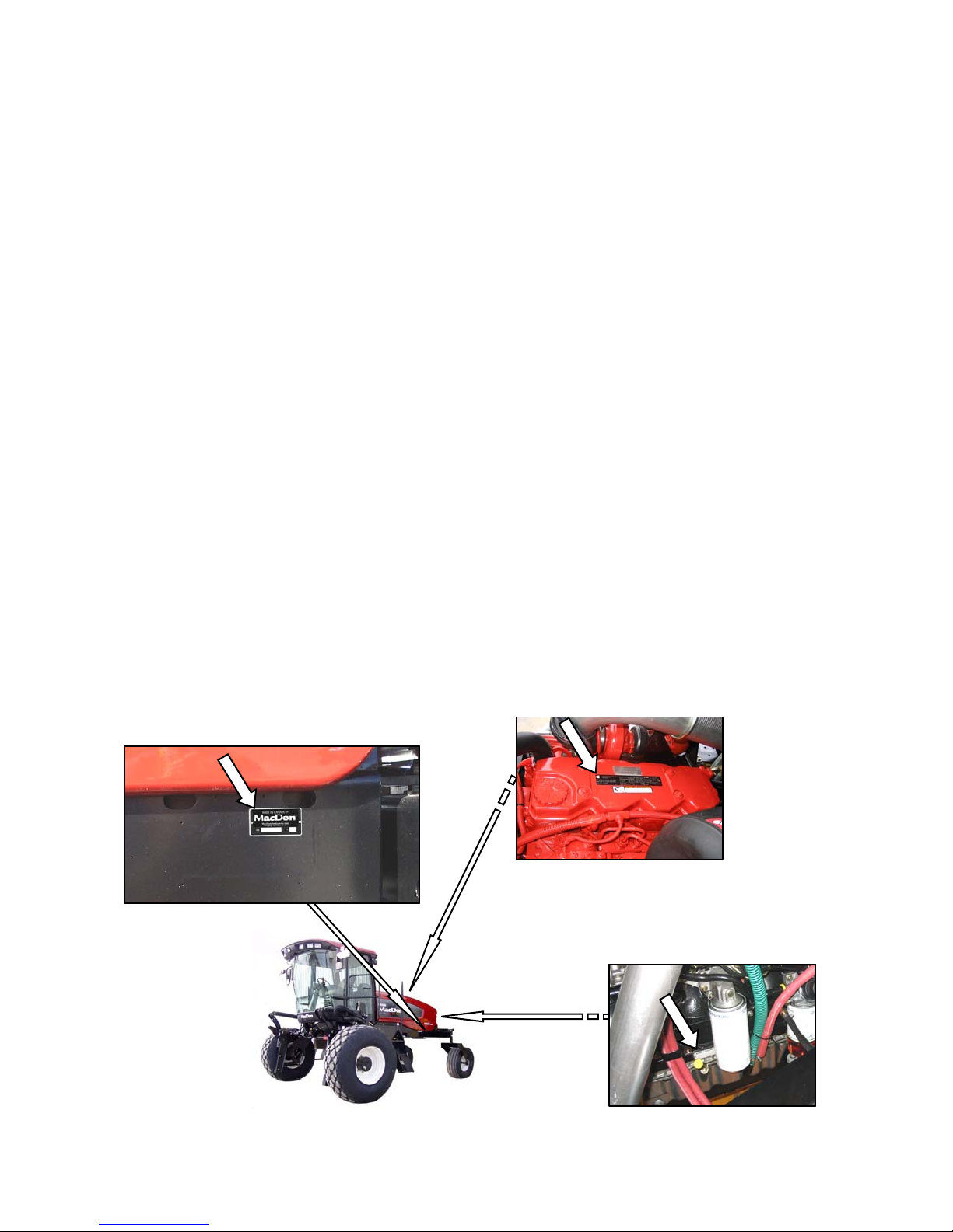
RECORD THE SERIAL NUMBERS IN THE SPACES BELOW.
Windrower ___________________________
Serial Number plate is located on the left cabforward side of the main frame, near the rear
corner.
Published: September, 2010
M150 Diesel Engine_____________________________
Serial Number plate is located on the top face of the
engine cylinder head cover.
M200 Diesel Engine_____________________________
Serial Number plate is located on the lower right cab-
forward side of the engine block.
Form 169017 / 169087 / 169095 1 Revision C
Page 4

TABLE OF CONTENTS
Section/Title Page
INTRODUCTION ...............................................................................................................................1
1
2 SAFETY ............................................................................................................................................6
2.1 SAFETY ALERT SYMBOL .......................................................................................................6
2.2 SIGNAL WORDS ......................................................................................................................6
2.3 SAFETY SIGNS ........................................................................................................................6
2.3.1 Safety Sign Installation .................................................................................................................. 6
2.3.2 Safety Sign Locations .................................................................................................................... 6
2.4 GENERAL SAFETY ................................................................................................................11
3 DEFINITIONS ..................................................................................................................................13
4 SPECIFICATIONS ..........................................................................................................................14
4.1 WINDROWER DIMENSIONS .................................................................................................14
4.2 SPECIFICATIONS ..................................................................................................................15
5 OPERATOR’S STATION ................................................................................................................17
5.1 OPERATOR CONSOLE .........................................................................................................17
5.2 OPERATOR PRESENCE .......................................................................................................18
5.2.1 Header Drive ................................................................................................................................ 18
5.2.2 Engine and Transmission ............................................................................................................ 18
5.3 SEAT ADJUSTMENTS ...........................................................................................................18
5.4 TRAINING SEAT ....................................................................................................................19
5.5 SEAT BELTS ..........................................................................................................................19
5.6 STEERING COLUMN ADJUSTMENT ...................................................................................19
5.7 LIGHTS ...................................................................................................................................20
5.7.1 Cab-Forward Lighting - Field ....................................................................................................... 20
5.7.2 Engine-Forward Lighting - Road .................................................................................................. 21
5.7.3 Cab-Forward Lighting - Road (Optional) ...................................................................................... 21
5.7.4 Beacon Lighting - Export (N.A. Optional) ..................................................................................... 22
5.7.5 Slow Moving Vehicle (SMV) Signs ............................................................................................... 22
5.8 WINDSHIELD WIPERS ..........................................................................................................23
5.9 REAR VIEW MIRRORS ..........................................................................................................23
5.10 CAB TEMPERATURE ............................................................................................................23
5.10.1 Heater Shut-Off Valve .................................................................................................................. 23
5.10.2 Air Distribution ............................................................................................................................. 23
5.10.3 Controls ....................................................................................................................................... 24
5.10.4 A/C Compressor Protection ......................................................................................................... 24
5.11 INTERIOR LIGHTS .................................................................................................................24
5.12 OPERATOR AMENITIES .......................................................................................................25
5.13 RADIOS ..................................................................................................................................26
5.13.1 AM/FM Radio ............................................................................................................................... 26
5.13.2 Antenna Mounting ........................................................................................................................ 26
5.14 HORN .....................................................................................................................................26
5.15 ENGINE CONTROLS/GAUGES .............................................................................................27
5.16 WINDROWER CONTROLS ...................................................................................................28
5.17 HEADER CONTROLS ............................................................................................................29
5.17.1 Header Engage Switch ................................................................................................................ 29
5.17.2 Header Drive Reverse Button ...................................................................................................... 29
5.17.3 Ground Speed Lever (GSL) Header Switches ............................................................................. 30
5.17.4 Console Header Switches ............................................................................................................ 32
5.18 CAB DISPLAY MODULE (CDM) ............................................................................................33
5.18.1 Engine and Windrower Functions ................................................................................................ 33
5.18.2 Header Functions ........................................................................................................................ 33
5.18.3 Operating Screens ....................................................................................................................... 34
5.18.4 Cab Display Module (CDM) Warnings/Alarms ............................................................................. 41
5.18.5 Cab Display Module (CDM) Programming ................................................................................... 44
5.18.6 Setting Guidelines ........................................................................................................................ 50
5.18.7 CDM and WCM Fault Codes ....................................................................................................... 50
6 OPERATION ...................................................................................................................................51
6.1 OWNER/OPERATOR RESPONSIBILITIES ...........................................................................51
Form 169017 / 169087 / 169095 2 Revision C
Page 5

TABLE OF CONTENTS
SYMBOL DEFINITIONS ......................................................................................................... 51
6.2
6.2.1 Engine Functions ......................................................................................................................... 51
6.2.2 Windrower Operating Symbols .................................................................................................... 51
6.2.3 Header Functions ........................................................................................................................ 52
6.3 WINDROWER OPERATION .................................................................................................. 53
6.3.1 Operational Safety ....................................................................................................................... 53
6.3.2 Break-In Period ............................................................................................................................ 53
6.3.3 Pre-Season Check ...................................................................................................................... 54
6.3.4 Daily Check ................................................................................................................................. 54
6.3.5 Engine Operation ......................................................................................................................... 55
6.3.6 Driving The Windrower ................................................................................................................ 59
6.3.7 Adjustable Caster Tread Width .................................................................................................... 65
6.3.8 Transporting ................................................................................................................................ 66
6.3.9 Storage ........................................................................................................................................ 76
6.4 HEADER OPERATION ........................................................................................................... 77
6.4.1 Header Lift Cylinder Stops ........................................................................................................... 77
6.4.2 Header Flotation .......................................................................................................................... 78
6.4.3 Levelling ...................................................................................................................................... 81
6.4.4 Header Drive ............................................................................................................................... 82
6.4.5 Header Angle ............................................................................................................................... 83
6.4.6 Cutting Height .............................................................................................................................. 85
6.4.7 Double Windrowing ..................................................................................................................... 87
6.5 D SERIES HEADER OPERATION ......................................................................................... 88
6.5.1 Header Attachment ...................................................................................................................... 88
6.5.2 Header Detachment .................................................................................................................... 91
6.5.3 Header Position ........................................................................................................................... 94
6.5.4 Reel Fore-Aft Position ................................................................................................................. 94
6.5.5 Reel Height .................................................................................................................................. 94
6.5.6 Reel Speed .................................................................................................................................. 94
6.5.7 Draper Speed .............................................................................................................................. 97
6.5.8 Knife Speed ................................................................................................................................. 99
6.5.9 Deck Shift (Optional) ................................................................................................................. 100
6.6 A SERIES HEADER OPERATION ....................................................................................... 101
6.6.1 Header Attachment .................................................................................................................... 101
6.6.2 Header Detachment .................................................................................................................. 104
6.6.3 Auger Speed.............................................................................................................................. 106
6.6.4 Reel Speed ................................................................................................................................ 107
6.6.5 Knife Speed ............................................................................................................................... 108
6.7 R SERIES HEADER OPERATION ....................................................................................... 109
6.7.1 Header Attachment .................................................................................................................... 109
6.7.2 Header Detachment .................................................................................................................. 112
6.7.3 Disc Speed ................................................................................................................................ 114
6.7.4 Converging Drum Assemblies - Grass Seed Header ................................................................ 115
7 MAINTENANCE AND SERVICING .............................................................................................. 116
7.1 PREPARATION FOR SERVICING ...................................................................................... 116
7.1.1 Welding Precautions .................................................................................................................. 116
7.2 RECOMMENDED SAFETY PROCEDURES ....................................................................... 116
7.3 MAINTENANCE SPECIFICATIONS .................................................................................... 117
7.3.1 Recommended Fuel, Fluids and Lubricants .............................................................................. 117
7.3.2 Recommended Torques ............................................................................................................ 118
7.3.3 Conversion Chart ....................................................................................................................... 120
7.4 ENGINE COMPARTMENT HOOD ....................................................................................... 121
7.5 MAINTENANCE PLATFORMS ............................................................................................. 122
7.5.1 Opening/Closing Platforms ........................................................................................................ 122
7.5.2 Opening/Closing Platform for Major Servicing ........................................................................... 122
7.6 LUBRICATING THE WINDROWER ..................................................................................... 124
7.6.1 Procedure .................................................................................................................................. 124
7.6.2 Lubrication Points ...................................................................................................................... 124
7.7 OPERATOR’S STATION ...................................................................................................... 126
7.7.1 Seat Belts .................................................................................................................................. 126
7.7.2 Safety Systems .......................................................................................................................... 126
7.7.3 GSL Adjustments ....................................................................................................................... 127
7.7.4 Steering Adjustments ................................................................................................................ 128
Form 169017 / 169087 / 169095 3 Revision C
Page 6

TABLE OF CONTENTS
7.7.5 Park Brake ................................................................................................................................. 130
7.7.6 HVAC System ............................................................................................................................ 132
7.8 CUMMINS ENGINE (M150) ................................................................................................ 135
7.8.1 General Engine Inspection ......................................................................................................... 135
7.8.2 Manually Turning Engine ........................................................................................................... 135
7.8.3 Oil Level ..................................................................................................................................... 136
7.8.4 Changing Oil and Oil Filter ......................................................................................................... 137
7.8.5 Air Intake System ....................................................................................................................... 139
7.8.6 Fuel System ............................................................................................................................... 142
7.8.7 Engine Cooling System .............................................................................................................. 147
7.8.8 Gearbox ..................................................................................................................................... 150
7.8.9 Exhaust System ......................................................................................................................... 152
7.8.10 Belts ........................................................................................................................................... 153
7.8.11 Engine Speed ............................................................................................................................ 154
7.9 CAT ENGINE (M200) .......................................................................................................... 155
7.9.1 General Engine Inspection ......................................................................................................... 155
7.9.2 Oil Level ..................................................................................................................................... 155
7.9.3 Changing Oil and Oil Filter ......................................................................................................... 156
7.9.4 Air Intake System ....................................................................................................................... 157
7.9.5 Aspirator Hose and Check Valve Replacement ......................................................................... 159
7.9.6 Fuel System ............................................................................................................................... 161
7.9.7 Engine Cooling System .............................................................................................................. 166
7.9.8 Gearbox ..................................................................................................................................... 170
7.9.9 Exhaust System ......................................................................................................................... 172
7.9.10 Belts ........................................................................................................................................... 173
7.10 COOLING BOX .................................................................................................................... 175
7.10.1 Cooling Box Screen ................................................................................................................... 175
7.10.2 Cooling Box Maintenance .......................................................................................................... 177
7.11 ELECTRICAL SYSTEM ....................................................................................................... 179
7.11.1 Battery ....................................................................................................................................... 179
7.11.2 Headlights - Engine-Forward ..................................................................................................... 184
7.11.3 Field lights - Cab-Forward .......................................................................................................... 186
7.11.4 Flood Lights - Forward ............................................................................................................... 186
7.11.5 Flood Lights - Rear .................................................................................................................... 187
7.11.6 Red and Amber Lights ............................................................................................................... 188
7.11.7 Red Tail Lights (If Installed) ....................................................................................................... 189
7.11.8 Beacons (If Installed) ................................................................................................................. 189
7.11.9 Gauge Light ............................................................................................................................... 191
7.11.10 Dome Light ................................................................................................................................ 191
7.11.11 Ambient Light ............................................................................................................................. 191
7.11.12 Turn Signal Indicators ................................................................................................................ 191
7.11.13 Circuit Breakers and Fuses ........................................................................................................ 192
7.12 HYDRAULIC SYSTEM ........................................................................................................ 195
7.12.1 Oil Level ..................................................................................................................................... 195
7.12.2 Changing Hydraulic Oil .............................................................................................................. 196
7.12.3 Hydraulic Oil Cooler ................................................................................................................... 196
7.12.4 Hydraulic Oil Filters .................................................................................................................... 196
7.12.5 Header and Reel Hydraulics ...................................................................................................... 197
7.12.6 Traction Drive Hydraulics ........................................................................................................... 199
7.12.7 Hoses and Lines ........................................................................................................................ 200
7.13 WHEELS AND TIRES ......................................................................................................... 201
7.13.1 Drive Wheels ............................................................................................................................. 201
7.13.2 Caster Wheels ........................................................................................................................... 204
7.14 MAINTENANCE SCHEDULE .............................................................................................. 208
7.14.1 Break-In Inspections .................................................................................................................. 208
7.14.2 Interval Maintenance ................................................................................................................. 209
8 TROUBLESHOOTING ................................................................................................................. 212
8.1 ENGINE ............................................................................................................................... 212
8.2 ELECTRICAL ....................................................................................................................... 215
8.3 HYDRAULICS ...................................................................................................................... 215
8.4 HEADER DRIVE .................................................................................................................. 216
8.5 TRACTION DRIVE .............................................................................................................. 216
8.6 STEERING AND GROUND SPEED CONTROL ................................................................. 217
Form 169017 / 169087 / 169095 4 Revision C
Page 7

TABLE OF CONTENTS
CAB AIR ................................................................................................................................ 218
8.7
8.8 OPERATOR’S STATION ...................................................................................................... 220
9 OPTIONS / ATTACHMENTS ........................................................................................................ 221
9.1 REEL DRIVE AND LIFT PLUMBING ................................................................................... 221
9.2 WINDROWER HYDRAULIC COMPLETION FOR DRAPER HEADER REEL FORE-AFT . 221
9.3 DOUBLE WINDROW ATTACHMENT .................................................................................. 221
9.4 REVERSER VALVE AND PLUMBING ................................................................................. 221
9.5 BOOSTER SPRING KIT ....................................................................................................... 221
9.6 INTERNAL BOOSTER SPRING KIT .................................................................................... 221
9.7 LIGHT HEADER FLOTATION KIT ....................................................................................... 221
9.8 WINDSHIELD SHADES ....................................................................................................... 221
9.9 DISC HEADER VALVE ......................................................................................................... 221
9.10 AM/FM RADIO ...................................................................................................................... 221
9.11 CENTER-LINK SELF-ALIGNMENT KIT ............................................................................... 221
9.12 PRESSURE SENSOR KIT ................................................................................................... 221
9.13 HYDRAULIC CENTER-LINK ................................................................................................ 221
9.14 WEIGHT BOX ....................................................................................................................... 221
9.15 TOWING HARNESS ............................................................................................................. 221
9.16 SWATH ROLLER ................................................................................................................. 221
9.17 WARNING BEACONS .......................................................................................................... 222
9.18 AUTO-STEER ....................................................................................................................... 222
9.19 LIGHTING AND MARKING KIT FOR CAB-FORWARD ROAD TRAVEL ............................ 222
9.20 FAN AIR BAFFLE KIT .......................................................................................................... 222
INDEX ......................................................................................................................................................... 223
CDM / WCM FAULT CODES ..................................................................................................................... 226
M150 AND M200 ENGINE ERROR CODES .............................................................................................. 227
Form 169017 / 169087 / 169095 5 Revision C
Page 8
SAFETY
2 SAFETY
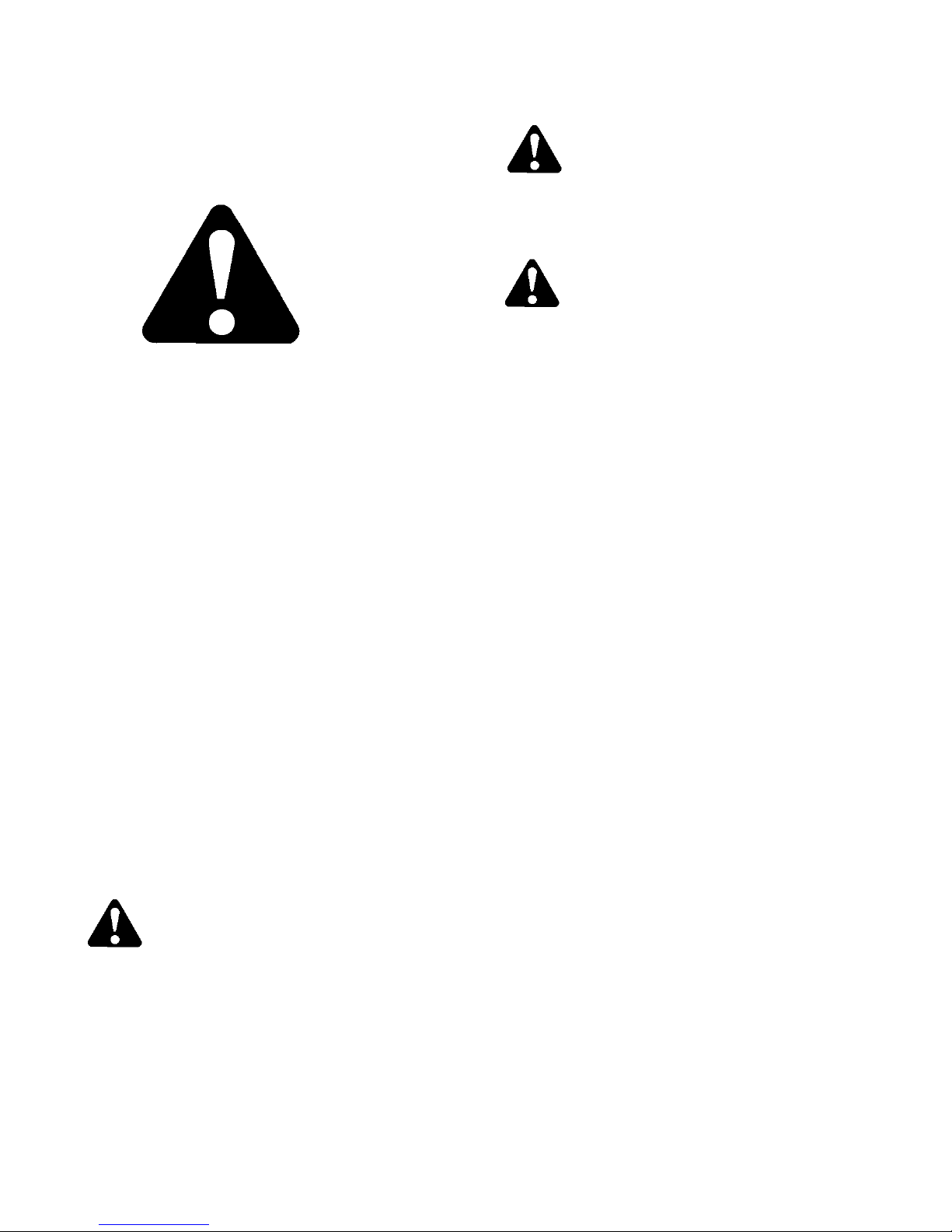
2.1 SAFETY ALERT SYMBOL
This safety alert symbol indicates important safety
messages in this manual and on safety signs on
the machine.
This symbol means:
ATTENTION!
BECOME ALERT!
YOUR SAFETY IS INVOLVED!
Carefully read and follow the safety message
accompanying this symbol.
WHY IS SAFETY IMPORTANT TO YOU?
ACCIDENTS DISABLE AND KILL.
ACCIDENTS COST.
ACCIDENTS CAN BE AVOIDED.
WARNING
Indicates a potentially hazardous situation
that, if not avoided, could result in death or
serious injury. It is also used to alert against
unsafe practices.
CAUTION
Indicates a potentially hazardous situation
that, if not avoided, may result in minor or
moderate injury. It is also used as a reminder
of good safety practices.
2.3 SAFETY SIGNS
2.3.1 SAFETY SIGN INSTALLATION
Refer to the illustration on this and following
pages, and proceed as follows:
a. Be sure the installation area is clean and dry.
b. Decide on the exact location before you remove
the decal backing paper.
c. Remove the smaller portion of the split backing
paper.
d. Place the sign in position and slowly peel back th e
remaining paper, smoothing the sign as it is
applied.
e. Small air pockets can be smoothed out or pricked
with a pin.
2.3.2 SAFETY SIGN LOCATIONS
2.2 SIGNAL WORDS
Note the use of the signal words DANGER,
WARNING, and CAUTION with safety messages.
The appropriate signal word for each message
has been selected using the following guidelines:
DANGER
Indicates an imminently hazardous situation
that, if not avoided, will result in death or
serious injury.
Form 169017 / 169087 / 169095 6 Revision C
The safety signs (decals) appear on the wind rower
at the locations approximately as shown.
• Keep safety signs clean and legible at all
times.
• Replace safety signs that are missing or
become illegible.
• If original parts on which a safety sign was
installed are replaced, be sure the repair part
also bears the current safety sign.
• Safety signs are available from your MacDon
Dealer Parts Department.
Page 9
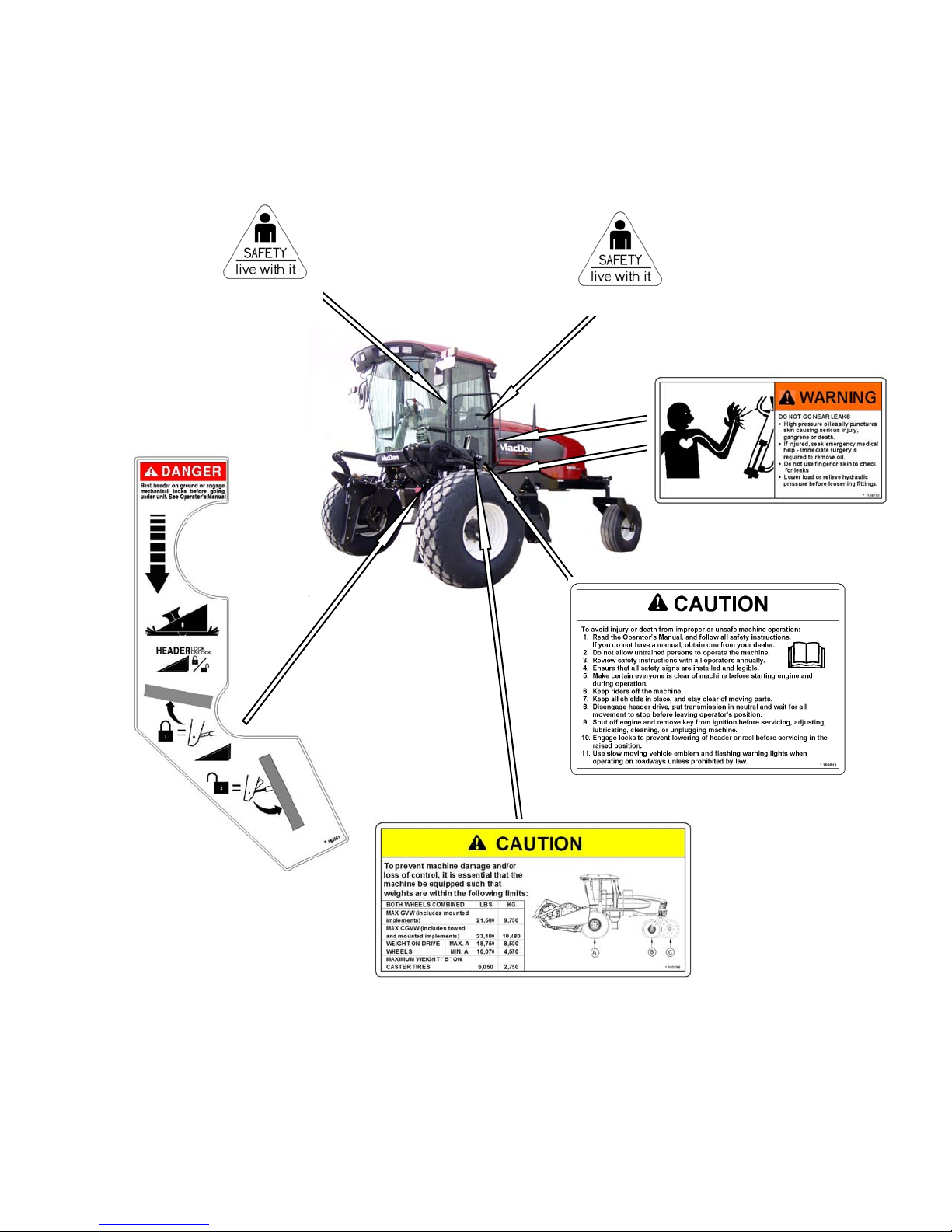
Safety Sign Locations (continued)
SAFETY
IN CAB #32744
BELOW DOOR HANDLE #32744
FRONT OF PLATFORM #134070
(HORIZONTAL FORMAT), AND
ON OIL RESERVOIR UNDER HOOD
(BOTH SIDES) #44944 (VERTICAL FORMAT)
LIFT LINKAGES #163561
Form 169017 / 169087 / 169095 7 Revision C
BEHIND DOOR ON SILL #109843
BEHIND DOOR ON SILL - LH SIDE ONLY
#160396
Page 10
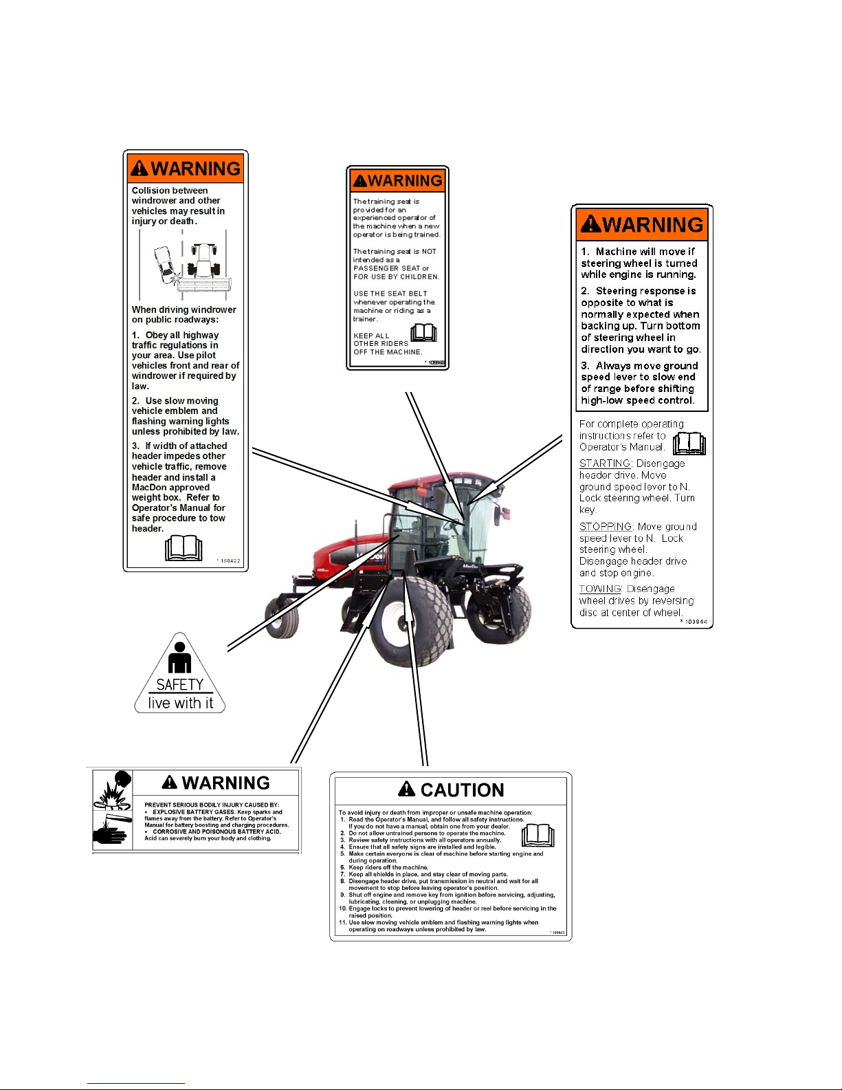
Safety Sign Locations
SAFETY
(continued)
IN CAB #109868
IN CAB #160422
BEL0W DOOR HANDLE #32744
FRONT OF PLATFORM #110989
IN CAB #109844
BEHIND DOOR ON SILL #109843
Form 169017 / 169087 / 169095 8 Revision C
Page 11
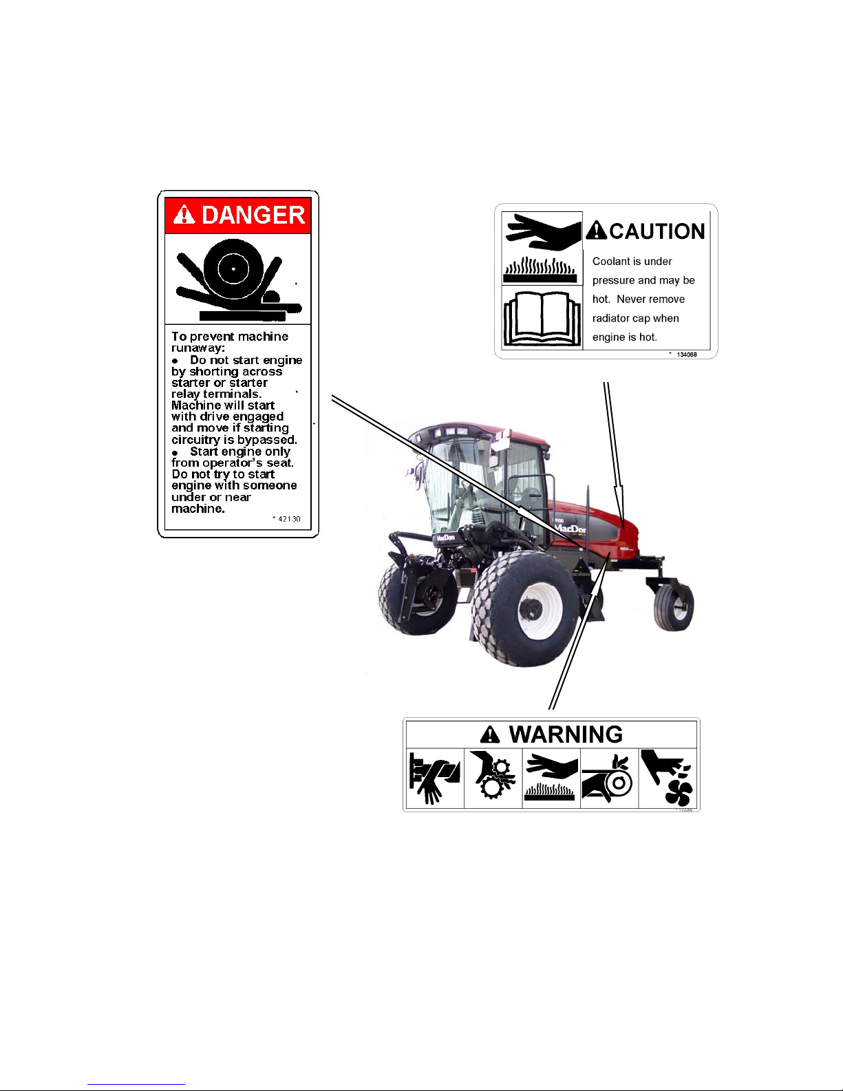
Safety Sign Locations (continued)
SAFETY
ON FAN SHROUD #134068
ON FRAME #42130
ON FRAME #110986
Form 169017 / 169087 / 169095 9 Revision C
Page 12
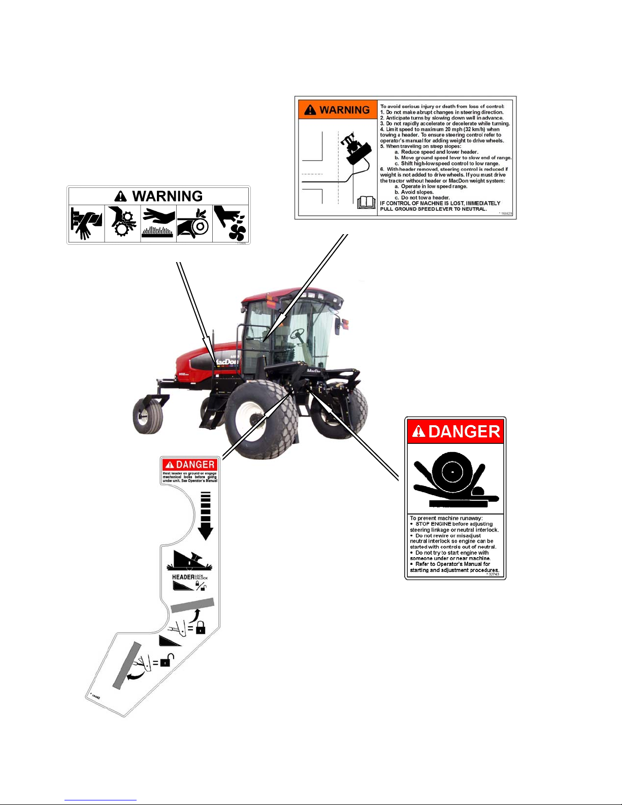
Safety Sign Locations
ON FRAME #110986
SAFETY
(continued)
ON DRINK COOLER #160429
ON LIFT LINKAGE #163562
Form 169017 / 169087 / 169095 10 Revision C
INSIDE FRAME #32743
Page 13
2.4 GENERAL SAFETY
CAUTION
The following are general farm safety
precautions that should be part of your
operating procedure for all types of
machinery.
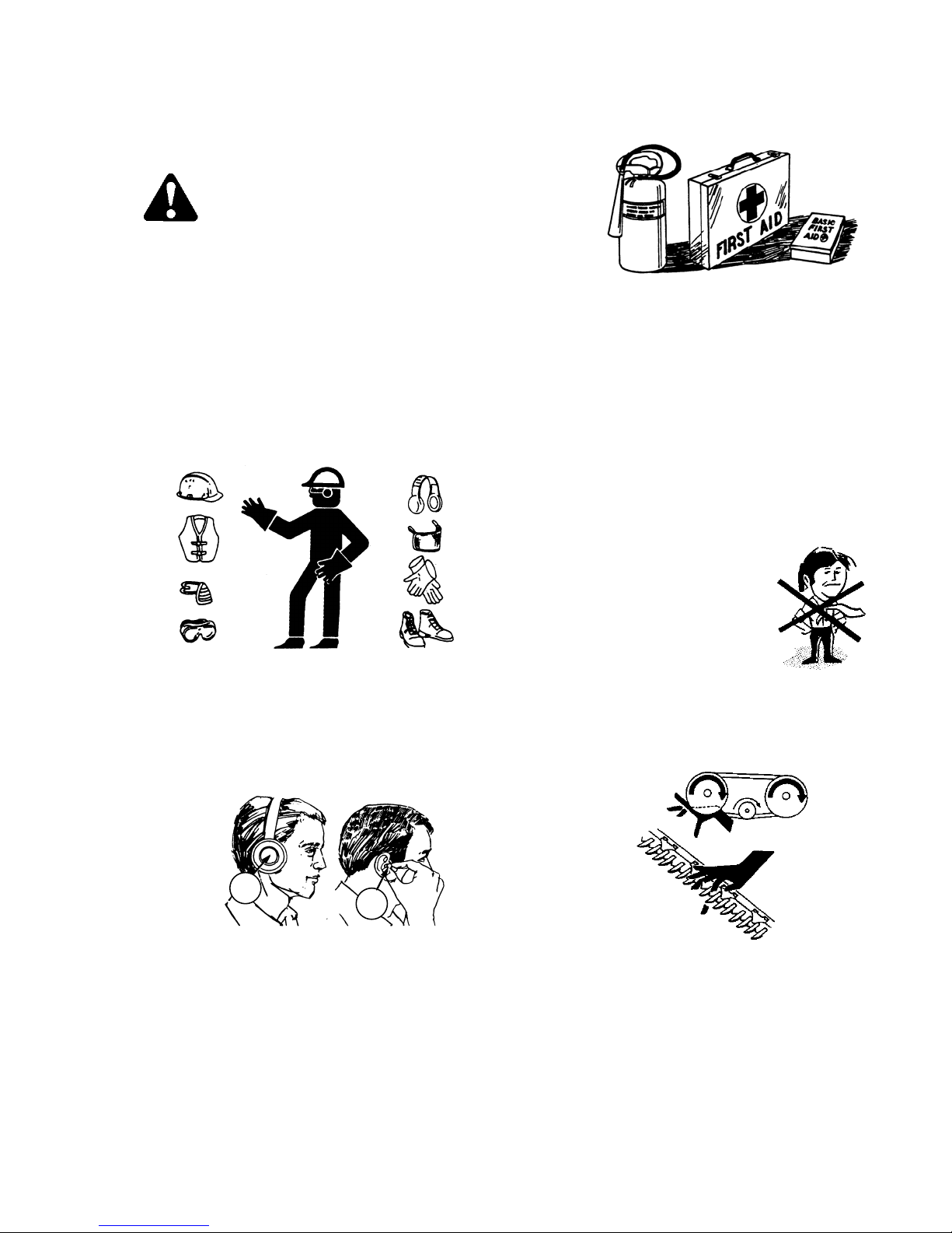
Protect yourself.
• When assembling, operating and servicing
machinery, wear all the protective clothing
and personal safety devices that COULD
be necessary for the job at hand. Don't
take chances.
• You may need:
SAFETY
• Provide a first-aid kit for use in case of
emergencies.
• Keep a fire extinguisher on the machine.
Be sure the extinguisher is properly
maintained and be familiar with its proper
use.
• Keep young children away from machinery
at all times.
• Be aware that accidents often happen
when the operator is tired or in a hurry to
get finished. Take the time to consider the
safest way. Never ignore warning signs of
fatigue.
• a hard hat.
• protective shoes with slip resistant
soles.
• protective glasses or goggles.
• heavy gloves.
• wet weather gear.
• respirator or filter mask.
A
B
• hearing protection. Be aware that
prolonged exposure to loud noise
can cause impairment or loss of
hearing. Wearing a suitable hearing
protective device such as ear muffs
(A) or ear plugs (B) protects against
objectionable or loud noises.
• Wear close-fitting
clothing and cover
long hair. Never wear
dangling items such
as scarves or
bracelets.
• Keep hands, feet, clothing and hair away
from moving parts. Never attempt to clear
obstructions or objects from a machine
while the engine is running.
• Keep all shields in place. Never alter or
remove safety equipment. Make sure
driveline guards can rotate independently
of the shaft and can telescope freely.
• Use only service and repair parts made or
approved by the equipment manufacturer.
Substituted parts may not meet strength,
design, or safety requirements.
Form 169017 / 169087 / 169095 11 Revision C
(continued next page)
Page 14

• Do not modify the machine. Unauthorized
modifications may impair the function
and/or safety and affect machine life.
• Stop engine and remove key from ignition
before leaving Operator’s seat for any
reason. A child or even a pet could engage
an idling machine.
SAFETY
• Keep the area used for servicing
machinery clean and dry. Wet or oily floors
are slippery. Wet spots can be dangerous
when working with electrical equipment.
Be sure all electrical outlets and tools are
properly grounded.
• Use adequate light for the job at hand.
• Keep machinery clean. Straw and chaff on
a hot engine are a fire hazard. Do not allow
oil or grease to accumulate on service
platforms, ladders or controls. Clean
machines before storage.
• Never use gasoline, naphtha or any volatile
material for cleaning purposes. These
materials may be toxic and/or flammable.
• When storing machinery, cover sharp or
extending components to prevent injury
from accidental contact.
Form 169017 / 169087 / 169095 12 Revision C
Page 15

SPECIFICATIONS
3 DEFINITIONS
TERM DEFINITION
API American Petroleum Institute
ASTM American Society of Testing And Materials
Cab-Forward Windrower operation with the operator and cab facing in the direction of travel
CDM Cab Display Module
DWA Double Windrow Attachment
Engine-Forward Windrower operation with the operator and engine facing in the direction of travel
ISC Integrated Speed Control
N-DETENT The slot opposite the neutral position on operator’s console
rpm Revolutions per minute
SAE Society Of Automotive Engineers
WCM Windrower Control Module
Windrower Windrower with header attached
Windrower Tractor Power unit only. (Windrower without the header attached)
Form 169017 / 169087 / 169095 13 Revision C
Page 16
SPECIFICATIONS
4 SPECIFICATIONS
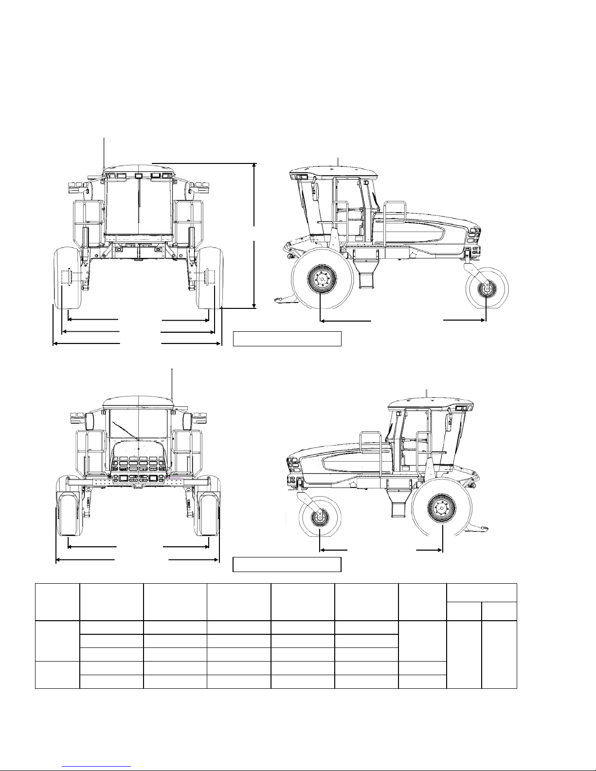
4.1 WINDROWER DIMENSIONS
Dimensions are with 18.4 - 26 drive tires and forked casters.
133 in. (3378 mm)
45.7 in. (1160
DRIVE
TIRE
CASTER
TIRE
TREAD
HUBS
TIRES
TREAD
CASTERS
WHEEL
POSITION
Inner / Outer - 138.7 (3522) - -
Outer / Outer 134.2 (3410) 146.1 (3712) - 157.1 (3990)
Inner / Inner 120.1 (3050) 131.6 (3342) - 150.0 (3810)
Minimum 93.2 (2367) - 115.4 (2932) - Maximum 135.8 (3448) - 158.0 (4013) - -
TREAD
Inch (mm)
CAB - FORWARD
ENGINE - FORWARD
HUBS
Inch (mm)
CASTERS
Inch (mm)
Inch (mm)
WHEEL BASE
WHEEL BASE
TIRES
SHIPPING
Inch (mm)
142.9
(3630)
WHEEL BASE
Inch (mm)
CAB
FWD
158.3
(4021)
ENG
FWD
120.7
(3066)
Form 169017 / 169087 / 169095 14 Revision C
Page 17

SPECIFICATIONS
4.2 SPECIFICATIONS
M150 M200
ENGINE
Type Cummins QSB -130 4 Cyl. Turbo Cat C6.6 6 Cyl. Turbo
Displacement 275 cu.in. (4.5 L) 403 cu.in. (6.6 L)
Power
Bore 4.04 in. (102 mm) 4.13 in. (105 mm)
Stroke 5.39 in. (137 mm) 5.00 in. (127 mm)
Maximum RPM (no load) 2270 - 2330 2250 - 2300
Idle RPM 1100 1100
Rated
Peak
130 hp (97 kW) @ 2200 rpm 213 hp (159 kW) @ 2200 rpm
140 hp (104 kW) @ 2000 rpm 220 hp (164 kW) @ 2000 rpm
ELECTRICAL SYSTEM
Recommended Battery (2)
Alternator 130 amp 120 amp
Starter
Working Lights
12 Volt, Min. 750CCA, Max Dim - 13 x 6.81 x 9.43 in. (330 x 173 x 240 mm).
Group Rating 31A. Heavy Duty / Off Road / Vibration Resistant.
TRACTION DRIVE
Type Hydrostatic, 3 Speed Electric Shift
Wet Type
11
Field (Cab-Forward)
Speed
Transmission
Final Drive
Wheel Motor Displ.
Reverse (Cab-Forward)
Transport (Engine-Forward)
Type
Displacement
Flow
Type
Ratio
Low Range
Mid Range
High Range
SYSTEM CAPACITIES
Fuel Tank
Cooling
Hydraulic Reservoir
HEADER DRIVE
Type Hydraulic, Load Sensing Variable Displacement
Displacement
Pump A - 0 - 2.75 cu.in. (0 - 45 cc)
Pump B - 0 - 2.32 cu.in. (0 - 38 cc)
Low Range 0 - 11 mph (17.7 km/h)
Mid Range 0 - 16 mph (25.7 km/h)
6 mph (9.6 km/h)
High Range 0 - 23 mph (37 km/h)
2 Piston Pumps - 1 per Drive Wheel.
2.65 cu.in. (44 cc)
40 U.S. gpm (151 L/min)
Planetary Gearbox
30.06 : 1
4.15 cu.in. (68 cc)
2.93 cu.in. (48 cc)
2.0 cu.in. (33 cc)
97 U.S. Gallons (378 L)
5.1 U.S. Gallons (20 L)
17.2 U.S. Gallons (66 L)
Pumps A & B - 0 - 3.11 cu.in. (0 - 51 cc)
Piston Pumps
Form 169017 / 169087 / 169095 15 Revision C
Flow
Max
Pressure
Pump A
Pump B
Pump A
Pump B
0 - 27 U.S. gpm (102 L/min) 0 - 39 U.S. gpm (148 L/min)
0 - 24 U.S. gpm (91 L/min) 0 - 34 U.S. gpm (128 L/min)
4000 psi (27.58 MPa) 4800 psi (33.10 MPa)
3200 psi (22.06 MPa) 4800 psi (33.10 MPa)
(continued next page)
Page 18

SPECIFICATIONS
M150 M200
HEADER LIFT/TILT
Type
Gear Pumps (2)
System Pressure (Relief / Max)
Displacement 0.84 cu.in. (13.8 cc)
Flow 11.5 U.S. gpm (46.5 L/min)
HEADER FLOTATION
Primary Adjustment
Fine Adjustment
Automatic
CAB
Width
Dimensions
Seat
Windshield Wiper
Heater
Air Conditioning
Electrical Outlets
Mirrors
Radio
Depth
Height
Volume
Driver
Training
Front
Rear
SYSTEM MONITORING
Speeds
Header
TIRE OPTIONS
Size
Pressure
Rear
Drive
Rear
Drive
FRAME AND STRUCTURE
Dimensions
Frame to Ground (Crop Clearance)
Weight
SK
NG Header Compatibility
DK
Base
Max GVW
Max CGVW
2500 psi (17.24 MPa)
Manual, External, Draw-Bolt With Springs (1 per side)
Hydraulic, In-Cab Switch
Hydraulic, 3 Programmable Settings For All Headers
(Deck Shift Compensation On Draper Headers)
63 in. (1600 mm)
68.3 in. (1735 mm) (at top of window)
64.6 in. (1640 mm)
125 cu.ft. (3540 L)
Adjustable Air-Ride Suspension, Seat Belt
Folding, Cab Mounted, Seat Belt
31.5 in. (800 mm) Blade
22 in. (560 mm) Blade
Two Speakers and Antenna Factory Installed. Radio Dealer Installed
One Inside (Transport), Two Outside (Field)
24,000 Btu/h (7038 W)
28,280 Btu/h (8288 W)
Two Live, Three On Ignition
Ground (mph or km/h), Engine (rpm), Knife (spm), Disc (rpm),
Height, Angle, Float, Optional Knife or
18.4 - 26 Bar, 18.4 - 26 Turf, 600-65 R28 Bar, 23.1 - 26 Turf, 580-70 R26 Turf
Reel (rpm or mph/km/h), Conveyor (Ref. No.)
Reel Drive Pressure
7.5 - 16SL Single Rib, 10 x 16 Front Steer Tire
16.5L - 16.1 Rib Implement Flotation, Forked Caster
Bar - 32 psi (221 kPa), Turf - 20 psi (138 kPa)
Refer to Section 4.1 WINDROWER DIMENSIONS
45.7 in. (1160 mm)
10,700 lb (4858 kg) 11,400 lb (5176 kg)
21,500 (9750 kg)
23,100 lb (10,480 kg)
A30S Auger, D50, D60S Harvest Header
A30D, A40D Auger, D60D Harvest Header
R80 Disc Rotary Header
NOTES: 1. Specifications and design are subject to change without notice, or obligation to revise previously sold units.
2. Weights do not include options
Form 169017 / 169087 / 169095 16 Revision C
.
Hydraulic
Height, Angle, Float, Knife Drive and
Reel Drive Pressures
10 psi (69 kPa)
Page 19
OPERATOR’S STATION
(
5 OPERATOR’S STATION
The Operator’s station is designed for operating
the windrower in a cab-forward mode (working
mode), or in an engine-forward mode (transport
mode).
The operator station, which includes the seat,
console, and steering column, pivots 180° so that
the operator maintains access to the windrower
controls and gauges regardless of the direction of
travel.
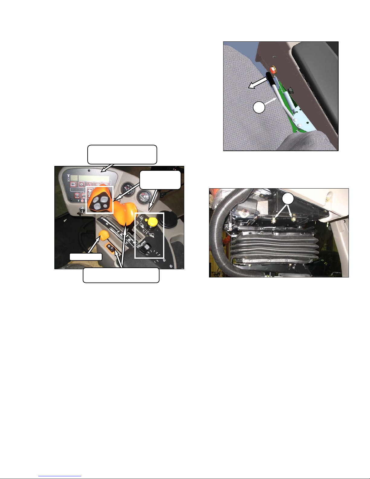
5.1 OPERATOR CONSOLE
ENGINE / WINDROWER
CAB DISPLAY MODULE
CDM)
HEADER
CONTROLS
SECTION 5.17
A
a. Pull lever (A), and slide console fore or aft to
desired position. The height also increases
slightly as the console is moved aft. Release lever
to lock console.
B
THROTTLE
WINDROWER CONTROLS
SECTION 5.16
The console contains controls to operate the
windrower, as well as amenities for the operator.
The console position is adjustable to suit each
particular operator. The console is attached to the
seat, and does not require adjustment when
repositioning the Operator’s seat.
b. To adjust only fore-aft, loosen nuts (B) under
console and move as required.
c. Tighten nuts.
Form 169017 / 169087 / 169095 17 Revision C
Page 20
OPERATOR’S STATION
5.2 OPERATOR PRESENCE
The Operator Presence System is a safety feature
that is designed to deactivate or alarm selected
systems when the operator is not seated at the
Operator’s station.
These systems include:
• Header Drive
• Engine and Transmission
5.2.1 HEADER DRIVE
• Requires the operator to be seated in the seat
in order to engage the header drive.
• Power is maintained to the header drive for 5
seconds after the operator leaves the seat,
and then the header shuts down.
• After the header has shutdown automatically,
the header engage switch must be moved to
“OFF” position, and back to the “ON” position
again to restart the header.
5.2.2 ENGINE AND TRANSMISSION
• The engine will not be allowed to start when
the header drive switch is engaged.
• The engine will not be allowed to start when
the transmission is not locked in neutral.
• The engine will shutdown when the windrower
is moving at 5 mph (8 km/h) or less, and the
operator leaves the seat.
• If the operator leaves the seat and the
transmission is not locked in neutral, after 5
seconds the lower display will flash “NOT IN
NEUTRAL” accompanied by an alarm.
• When the seat is in between cab-forward and
engine-forward positions, the engine will shut
off if the transmission is not locked in the
neutral position. The lower display will flash
“LOCK SEAT BASE” until the seat base is
locked into position.
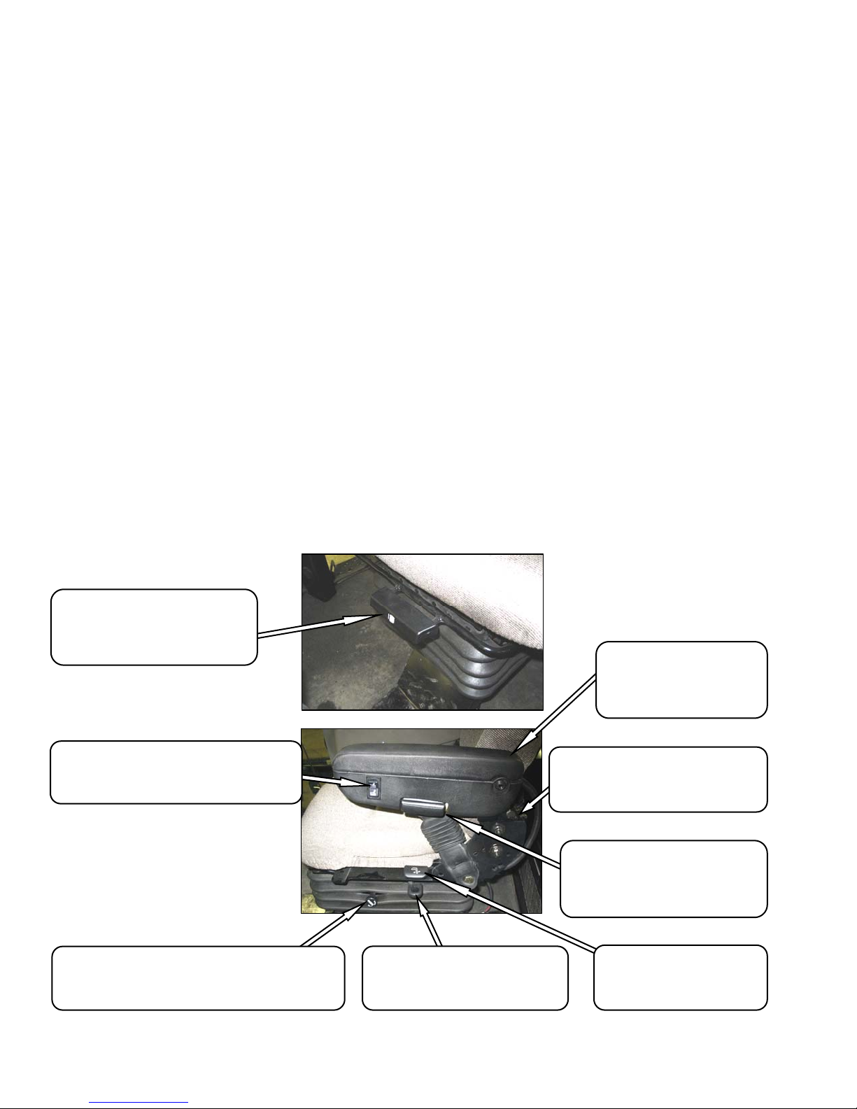
5.3 SEAT ADJUSTMENTS
The Operator’s seat has several adjustments.
Refer to the following illustration for the location
and description of each adjustment.
SEAT FORE-AFT POSITION
Adjusts Fore-Aft Position
Pull Lever Up To Release.
Move Seat Forward or Rearward.
Release Lever.
OPERATOR WEIGHT AND SEAT HEIGHT
Controls Suspension Stiffness and Seat Height
INCREASE - Press Upper Switch.
DECREASE - Press Lower Switch.
VERTICAL DAMPENER
Adjusts Suspension Dampening
INCREASE - Turn Knob Counter Clockwise
DECREASE - Turn Knob Clockwise
SEAT FORE-AFT ISOLATOR LOCK
Locks Seat Fore-Aft Isolator
LOCK - Push Lever Down.
UNLOCK - Pull Lever Up.
Raise Arm Rest For Easier
ARM REST
Access To Seat.
Lower Arm Rest After Seat
Belt Is Buckled.
LUMBAR SUPPORT
Adjusts Stiffness of Seat Back
INCREASE - Rotate Knob Upward.
DECREASE - Rotate Knob Downward.
ARM REST ANGLE
Adjusts Angle of Arm Rest
INCREASE - Rotate Knob Clockwise.
DECREASE - Rotate Knob Counter
Clockwise.
SEAT BACK ANGLE
Pull Lever Up To Release.
Position Seat Back As Desired.
Release Lever.
Form 169017 / 169087 / 169095 18 Revision C
Page 21
OPERATOR’S STATION
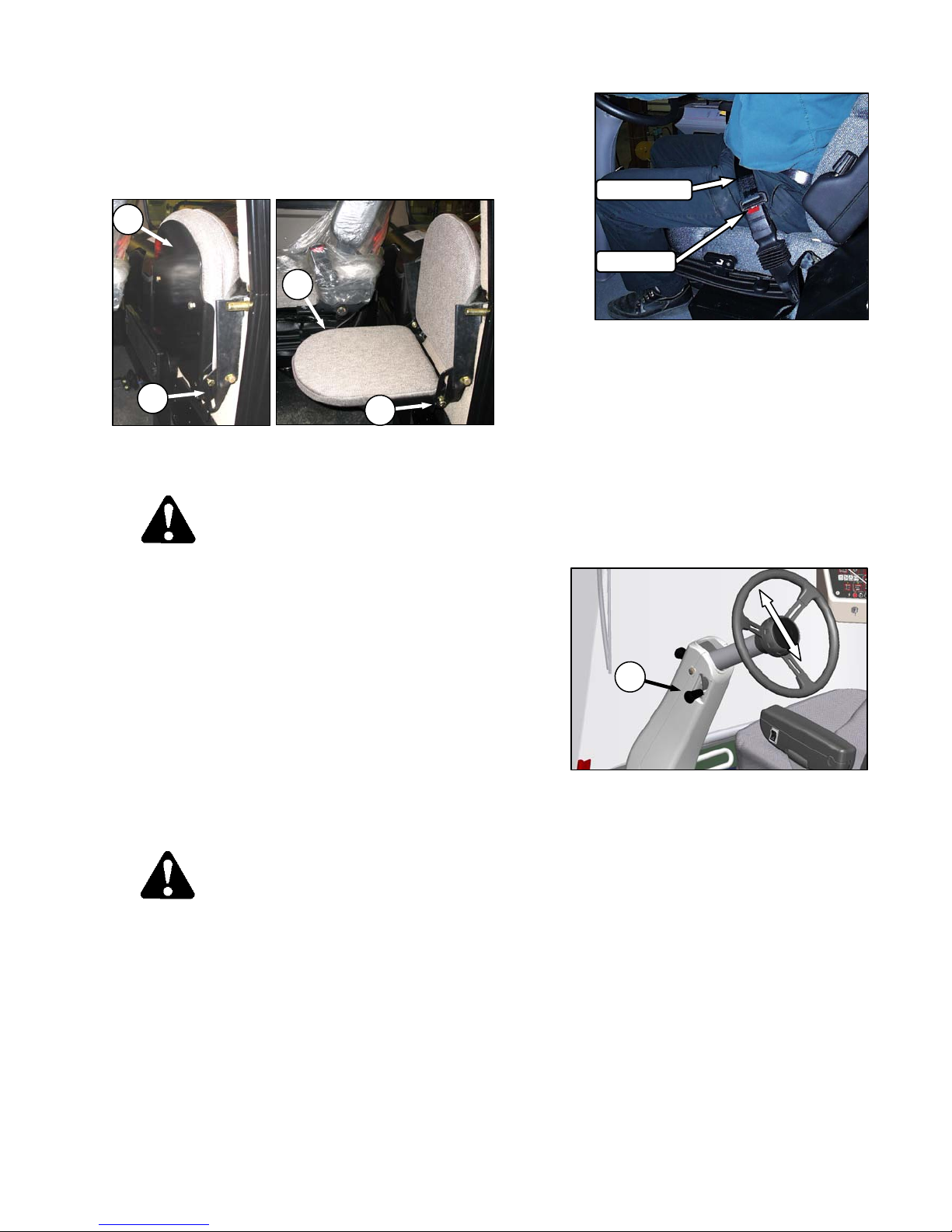
5.4 TRAINING SEAT
A wall mounted fold-up training seat, complete
with seat belt, is provided for use as described
below.
B
B
A
• To lower seat, lift latch (A), and lower seat (B).
• For storage, lift seat (B), and secure with latch (A).
A
WARNING
• The training seat is provided for an
experienced operator of the machine when
a new operator is being trained.
SEAT BELT
RELEASE
a. To fasten seat belt, pull belt completely across
your body. Push the metal eye into the buckle until
it locks. Adjust the position of the belt as low on
your body as possible.
b. To release, push the red button in the end of the
buckle, and separate the buckle and metal eye.
5.6 STEERING COLUMN ADJUSTMENT
The steering column can be adjusted to suit each
particular operator, and for easier entry to and e xit
from the seat.
• The training seat is NOT intended as a
PASSENGER SEAT or FOR USE BY
CHILDREN.
• USE THE SEAT BELT whenever operating
the machine, or riding as a trainer.
• KEEP ALL OTHER RIDERS OFF THE
MACHINE.
5.5 SEAT BELTS
The windrower is equipped with a seat belt on the
Operator’s and Trainer’s seats.
WARNING
• Before starting engine, securely fasten
your seat belt, and ensure trainer’s seat
belt is fastened if occupied. The seat belt
can help ensure your safety if it is used
and maintained.
• Never wear a seat belt loosely or with slack
in the belt system.
• Never wear the belt in a twisted condition
or pinched between the seat structural
members.
C
a. Hold onto steering wheel, lift handle (C), and
move steering wheel up or down to desired
position.
b. Release handle (C) to lock steering wheel
position.
Form 169017 / 169087 / 169095 19 Revision C
Page 22
OPERATOR’S STATION
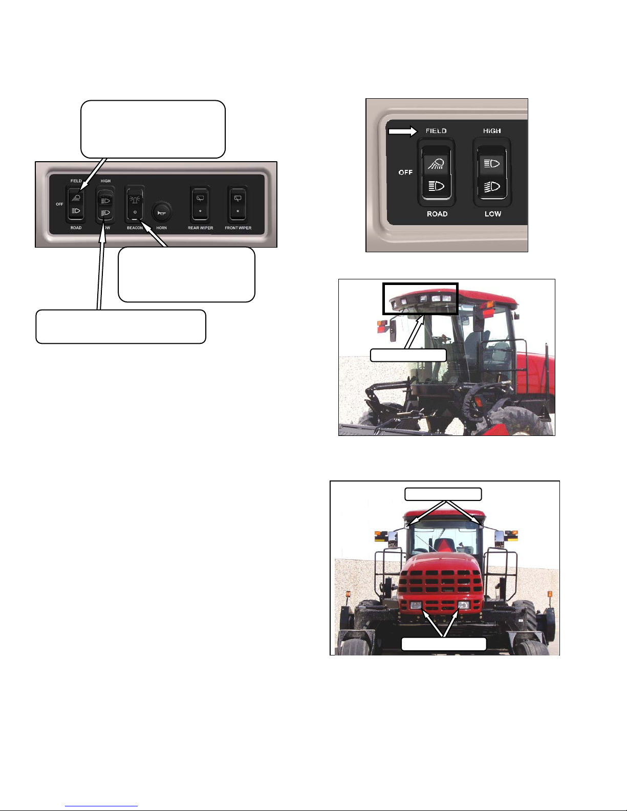
5.7 LIGHTS
LIGHTS
Controls field and transport lights
Field
Off
Road
BEACON
Controls Beacons On Cab
Standard for Export.
Optional for N.A.
On - Off
HIGH / LOW LIGHTS
Controls High / Low Beam For Road Lights
High - Low
The field and transport light switches are located
on a panel in the cab headliner. Refer to
illustrations on following pages for location of
lights.
5.7.1 CAB-FORWARD LIGHTING - FIELD
FIELD LIGHTS
The lighting is dependent upon the position of the
Operator’s station (i.e. cab-forward mode or
engine-forward mode).
The position of the Operator’s station
automatically determines the lighting.
IMPORTANT
Red reflector tape is applied to aft locations
to be visible in engine-forward mode.
Only amber tape is allowed in cab-forward
mode.
FRONT - CAB FWD
FIELD LIGHTS
SWATH LIGHTS
REAR - CAB FWD
Form 169017 / 169087 / 169095 20 Revision C
Page 23
OPERATOR’S STATION
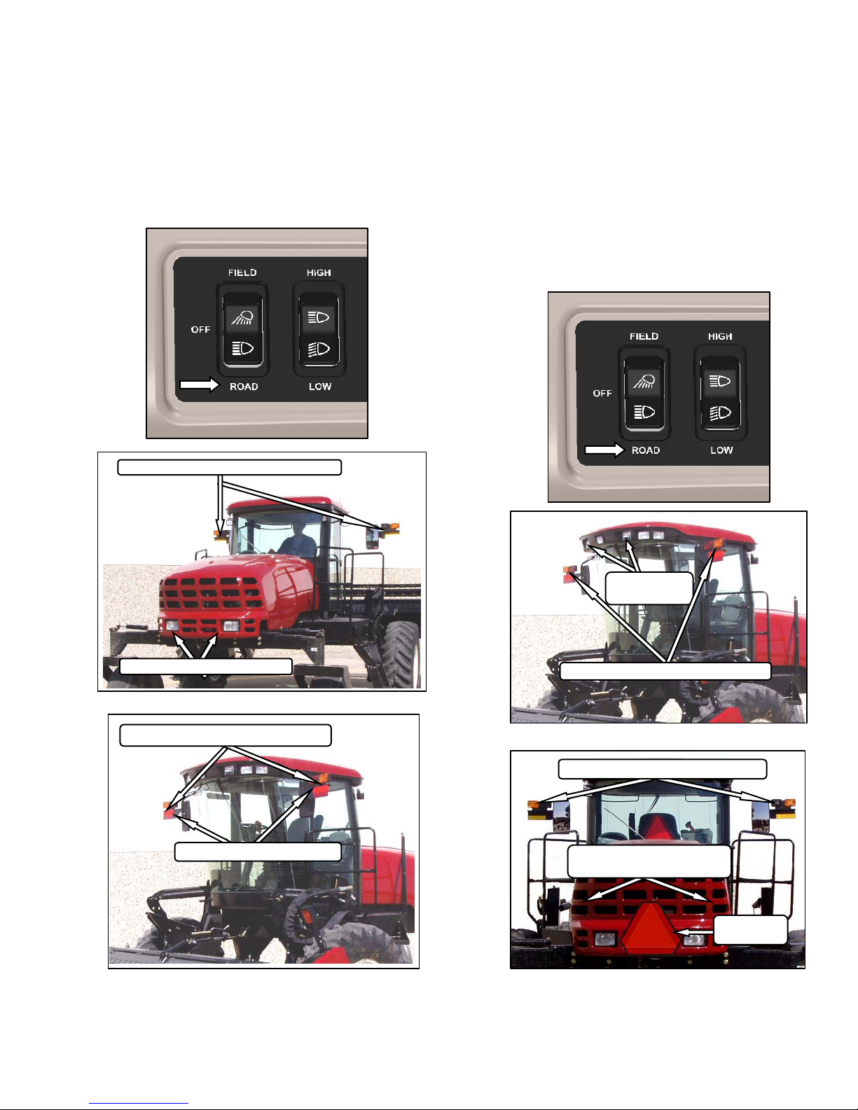
5.7.2 ENGINE-FORWARD LIGHTING ROAD
The following lights are on / functional when the
switch is in the ROAD position. The hazard lights
must be activated with the switch on the CDM
when driving on the road.
TURN SIGNALS / HAZARDS - AMBER
5.7.3 CAB-FORWARD LIGHTING - ROAD
(OPTIONAL)
If equipped, the following lights are functional
when the switch is in the ROAD position. The
hazard lights must be activated with the switch on
the CDM when driving on the road.
IMPORTANT
Optional red tail lighting and marking kit
must be installed so that road travel in the
cab-forward mode complies with road travel
regulations. See your MacDon Dealer.
HIGH / LOW LIGHTS - ROAD
FRONT - ENG FWD
TURN SIGNALS / HAZARDS - AMBER
TAIL / BRAKE LIGHTS - RED
REAR - ENG FWD
HI/LO LIGHTS
-ROAD
TURN SIGNALS/HAZARDS - AMBER
FRONT – CAB FWD
TURN SIGNALS/HAZARDS - AMBER
TAIL LIGHTS – RED
OPTIONAL BRAKE LIGHTS
SMV SIGN
OPTIONAL
REAR – CAB FWD
Form 169017 / 169087 / 169095 21 Revision C
Page 24
OPERATOR’S STATION
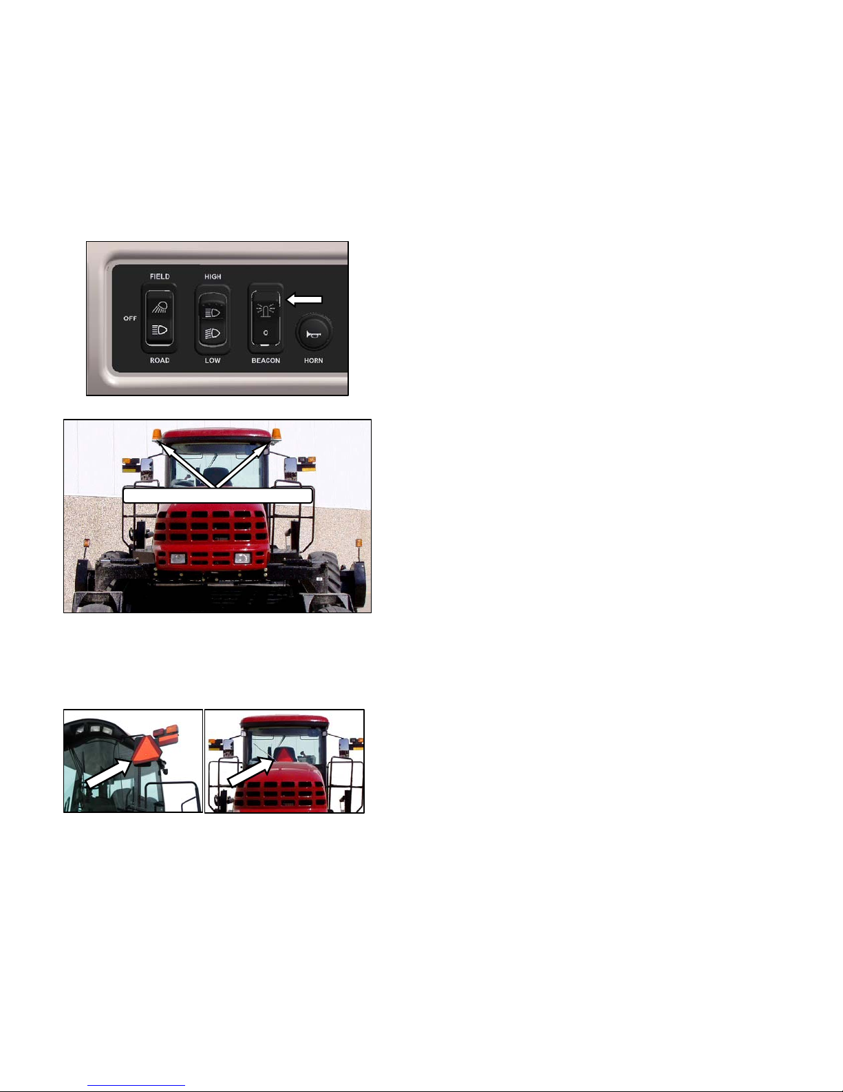
5.7.4 BEACON LIGHTING - EXPORT (N.A.
OPTIONAL)
The beacon lights are functional when the ignition
and the beacon switches are on.
The beacons must be used when driving on the
road.
BEACON LIGHTS - AMBER
5.7.5 SLOW MOVING VEHICLE (SMV)
SIGNS
ENGINE - FORWARD
The Slow Moving Vehicle (SMV) signs must be
visible when travelling on the road.
CAB - FORWARD
Form 169017 / 169087 / 169095 22 Revision C
Page 25
OPERATOR’S STATION
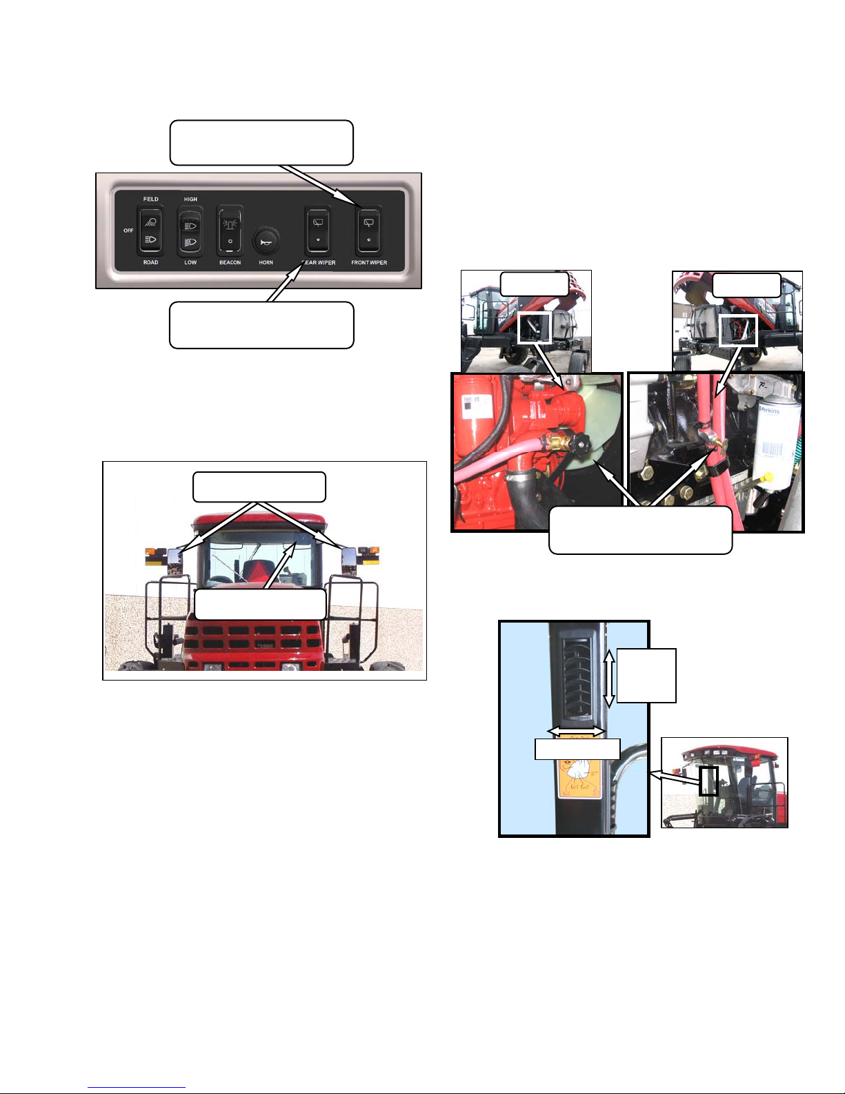
5.8 WINDSHIELD WIPERS
FRONT WIPER SWITCH
Controls Front Windshield Wiper
ON / OFF
REAR WIPER SWITCH
Controls Rear Windshield Wiper
ON / OFF
The windshield wiper controls are located in the
cab headliner. The illustration above designates
the controls as in the cab-forward mode.
5.9 REAR VIEW MIRRORS
REAR VIEW MIRRORS
CAB - FORWARD
5.10 CAB TEMPERATURE
The cab environment is controlled by a climatecontrol system that provides clean air-conditioned
or heated air for the operator.
The heater / evaporator / blower assembly is
located under the cab floorboard, and is
accessible from beneath the windrower.
5.10.1 HEATER SHUT-OFF VALVE
M150
HEATER SHUT-OFF VALVE
OPEN - Counter Clockwise
CLOSE - Clockwise
M200
REAR VIEW MIRROR
ENGINE - FORWARD
Two adjustable outside mounted mirrors provide
rear view vision when the windrower is operated in
the cab-forward mode.
A single interior mounted mirror provides rear view
vision in the engine-forward mode.
A shut-off valve at the engine allows the cab
heater to be isolated from the engine coolant.
OPEN
CLOSE
The valve must be open to provide heat to the
cab, but for maximum cooling, the valve can be
closed.
5.10.2 AIR DISTRIBUTION
Cab air distribution is controlled through
adjustable air vents. They are located in the cab
posts to provide window and operator ventilation
as shown in illustration.
Form 169017 / 169087 / 169095 23 Revision C
Page 26
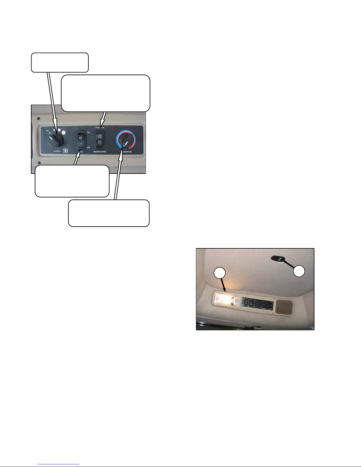
5.10.3 CONTROLS
BLOWER SWITCH
Controls Blower Speed
OFF / LO / MEDIUM / HI
FRESH AIR - Starts Booster Fan and
Filtered Outside Air Drawn Into Cab.
RECIRCULATE - Stops Booster Fan
and Cab Air Is Recirculated.
OUTSIDE AIR SWITCH
Controls Air Source
OPERATOR’S STATION
5.10.4 A/C COMPRESSOR PROTECTION
The compressor is protected from excessivel y low
and high pressures by two switches that shutdown
the compressor to prevent damage to the system.
• The LOW pressure switch opens when the
pressure falls to 5.1 - 10.9 psi (35 - 75 kPa),
and shuts down the compressor. When the
pressure rises to 17.6 - 26.4 psi (121 - 182
kPa), the switch closes, and allows the
compressor to run.
• The HIGH pressure switch opens and stops
the compressor when the pressure rises to
315 - 335 psi (2172 - 2310 kPa). When the
pressure falls to 220 - 280 psi (1517 - 1930
kPa), the switch closes, and allows the
compressor to run.
AIR CONDITIONING SWITCH
Controls A/C System
OFF - A/C Does Not Operate.
ON - A/C Operates With Blower
Switch On.
TEMPERATURE CONTROL
Controls Cab Temperature
INCREASE - Clockwise
DECREASE - Counter Clockwise
IMPORTANT
To distribute the oil throughout the system,
perform the following steps whenever the
machine is first started after storage for
more than one week:
a. Turn blower switch to the first position. Turn
temperature control switch to maximum heating,
and A/C control to “OFF”.
b. Start engine, and operate at low idle until engine is
warm.
c. Click A/C switch from "OFF" to "ON" for one
second, then back to "OFF" for 5 to 10 seconds.
Repeat this step ten times.
If the air conditioning system is shutdown by either
switch, locate the source of the problem, and
correct it before operating the system.
• The Windrower Control Module (WCM)
monitors the compressor operation, and when
it senses rapid pressure changes that cause
the compressor to rapidly engage and
disengage, a “CHECK A/C SYSTEM” will
appear on the CDM display.
5.11 INTERIOR LIGHTS
B
A
Form 169017 / 169087 / 169095 24 Revision C
Two interior lights are installed in the cab
headliner.
A low intensity LED light (A) is located directly
overhead to provide ambient lighting if desired,
and functions only when the road/field light switch
is on.
An on-off switch is located on the light.
The other interior light (B) is located on the
headliner switch panel and the push-on, push-off
button is located on the light.
Page 27
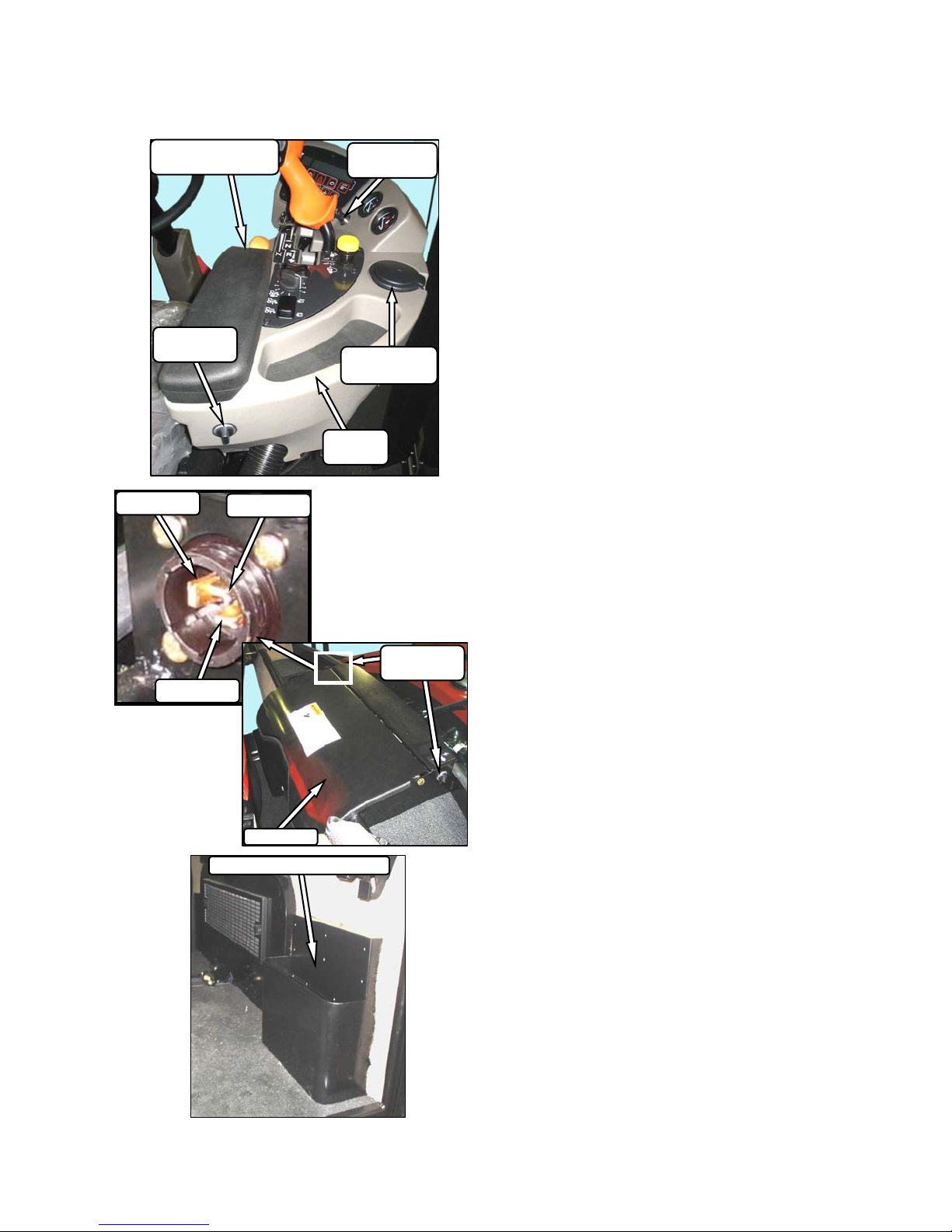
5.12 OPERATOR AMENITIES
OPERATOR’S STATION
UTILITY TRAY
UNDER ARMREST
AUXILIARY
POWER
SWITCHED
CIGARETTE
LIGHTER
ASHTRAY /
CUPHOLDER
UTILITY
TRAY
BATTERY
GROUND
AUXILIARY
POWER
COOLER
MANUAL STORAGE CASE
Form 169017 / 169087 / 169095 25 Revision C
Page 28
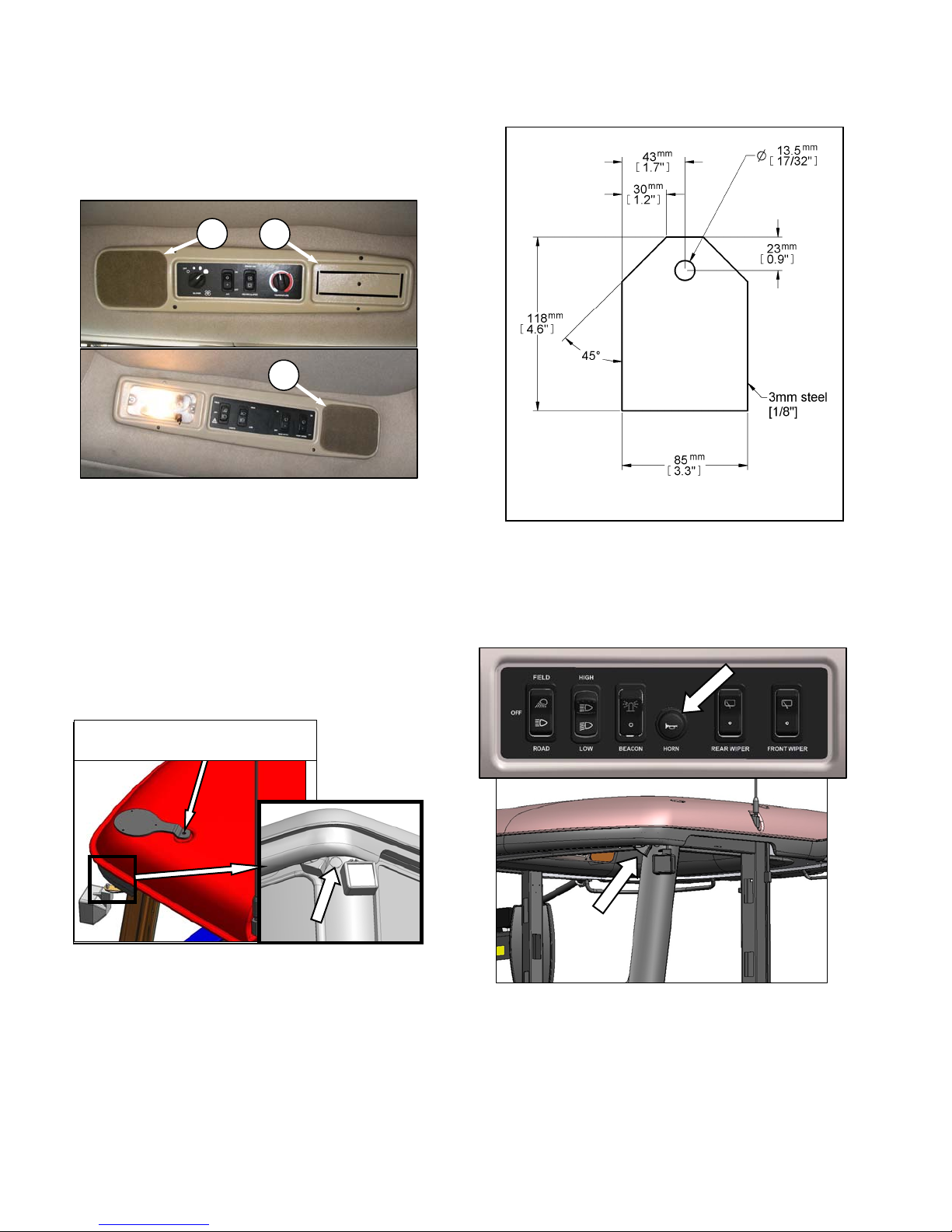
5.13 RADIOS
5.13.1 AM/FM RADIO
OPERATOR’S STATION
B
A
B
A radio is available as optional equipment from
your MacDon Dealer, and a space (A) is provided
in the cab headliner to accommodate the
installation. Two pre-wired speakers (B) have
been factory installed in the headliner.
Refer to M150 and M200 Self-Propelled
Windrower Unloading and Assembly instructional
manual for radio installation procedures.
Operating instructions are supplied with the radio.
11 GA. OR 3.0 mm CQHRS
IMPORTANT
Antenna base can only be installed on the
LH and RH rear cab roof bolts.
5.14 HORN
5.13.2 ANTENNA MOUNTING
REMOVE EXISTING BOLT AND
REINSTALL WITH ANTENNA BASE
A roof mounted antenna base for installing a
magnetic antenna is available as an option from
your MacDon Dealer.
Order part #160288, or see illustration for part
dimensions for a “homemade” version. It
accommodates most CB, 2-way radio and satellite
radio antennas.
A knockout for the antenna lead is provided on the
cab post.
The horn is activated by pushing the button
located on the panel in the headliner. The ignition
switch must be on.
Sound the horn three times prior to starting the
engine.
Form 169017 / 169087 / 169095 26 Revision C
Page 29
OPERATOR’S STATION
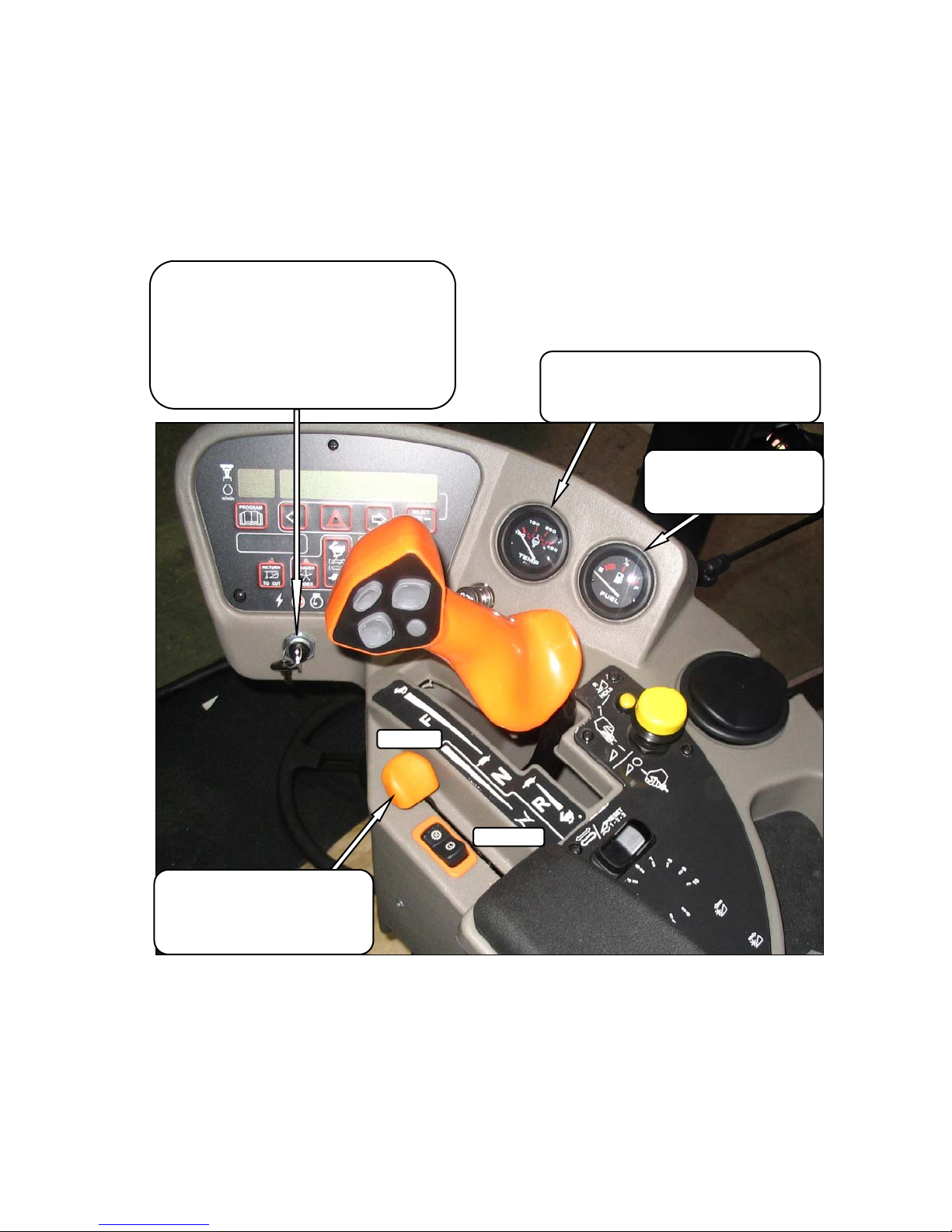
5.15 ENGINE CONTROLS/GAUGES
All engine controls and gauges are conveniently
located on the Operator’s console.
Refer to the following illustration for the location
and a description of each.
ACC - Fully Counter Clockwise
IGNITION SWITCH
OFF - All Electrical Systems Off
RUN - Clockwise
START- Fully Clockwise To Crank Engine
Release and Switch Returns to RUN
REMOVE KEY WHEN WINDROWER NOT IN USE.
KEY ALSO LOCKS DOORS.
ENGINE TEMPERATURE
Indicates Engine Coolant Temperature
Normal Running 180°- 225°F (82°-107°C).
Warning Tone Over 230°F (110°C).
FUEL
Indicates Fuel Level In Tank
E - Empty
F - Full
FULL
CLOSED
THROTTLE
Controls Engine RPM.
FULL - Push Lever Forward
OPERATING - See Section 6.3.6
CLOSED - Pull Lever Back
Form 169017 / 169087 / 169095 27 Revision C
Page 30
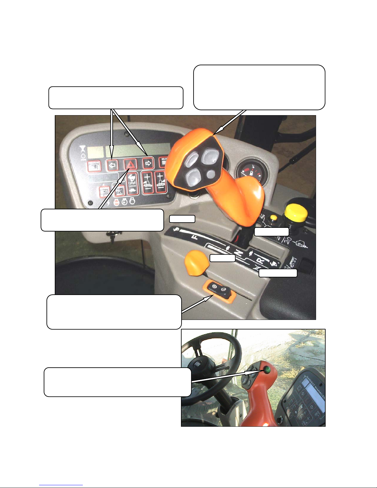
5.16 WINDROWER CONTROLS
TURN SIGNALS
Activates Turn Signals On Windrower and Header
Momentary Switches On Monitor
OPERATOR’S STATION
GROUND SPEED LEVER (GSL)
Controls Speed and Direction of Movement
F - Forward
N - Neutral
N-DETENT - Engages Neutral Interlock and Applies
Park Brake When Steering Locked In Center
R - Reverse
Activates Signals On Windrower Tractor and Header
HAZARD WARNING LIGHTS
Momentary Switch On Monitor
GROUND SPEED RANGE SWITCH
Shifts Transmission Speed Range
H - 0 - 23 mph (37 km/h). ENGINE-FORWARD ONLY.
- 0 -16 mph (25.7 km/h). CAB-FORWARD ONLY.
L - 0 -11 mph (17.7 km/h)
AUTO-STEER ENGAGEMENT SWITCH
Engages Auto-Steer System (If compatible system is installed).
ENGAGE - Click To Engage.
DISENGAGE - Turn Steering Wheel To Disengage.
FAST
N-DETENT
SLOW
REVERSE
Form 169017 / 169087 / 169095 28 Revision C
Page 31

OPERATOR’S STATION
5.17 HEADER CONTROLS
All header controls are conveniently located on the
Operator’s console, and on the GSL handle.
NOTE
Some controls are optional equipment, and
may not be present in your unit. Some
controls may be installed, but will be nonfunctional for certain headers.
5.17.1 HEADER ENGAGE SWITCH
5.17.2 HEADER DRIVE REVERSE BUTTON
HEADER REVERSE
ENGAGE - Push / Hold / Engage Header
DISENGAGE - Release Button
NOTE
The optional hydraulic reversing kit must be
installed.
IMPORTANT
To prevent improper operation and damage
to the reel on D Series draper headers
when the reverser kit is installed:
ENGAGE - Push Center and Pull Up
HEADER DRIVE
DISENGAGE - Push Down
Engages and disengages header drive.
IMPORTANT
Always move throttle lever back to idle
before engaging header drive. Do not
engage header with engine at full RPM.
If switching between A40D auger header
and D50 or D60 draper header, the hose
plumbing to the reverser valve must be
changed to suit the header type. Refer to
Instruction Form #169213 that was supplied
with the reversing kit.
• Reverses knife and conditioner on D Series draper
headers.
• Reverses reel, auger, knife and conditioner on A
Series auger headers.
• Not applicable for R Series rotary headers.
NOTE
To re-engage header drive, push down, and
pull up header drive knob.
Form 169017 / 169087 / 169095 29 Revision C
Page 32

OPERATOR’S STATION
5.17.3 GROUND SPEED LEVER (GSL)
HEADER SWITCHES
B
A
The GSL (A) contains switches for the following
header functions that are most often adjusted
while in operation to suit changing crop conditions.
All are momentary type switches.
5.17.3.1 Display Selector Switch
DISPLAY
SELECTOR
Selects and displays the settings in the CDM (B)
top line read-out for each of the header controls.
• Press switch to scroll through settings.
5.17.3.2 Reel Position Switches
The reel position switches perform the following
functions, depending on CDM programming, and
which header is attached:
A decal that identifies the switch functions is
located on the cab post above the Operator’s
console.
REEL FORWARD
REEL DOWN
DWA DOWN
REEL UP
REEL AFT
DWA UP
• Double Windrow Attachment (DWA) Position
on Draper and Auger Headers. See Section
6.4.7
• Reel Fore-Aft Position and Height on Draper
Headers. See Sections 6.5.4 and 6.5.5.
• Grass Seed Drum Position on Rotary
Headers. See Section 6.7.4.
• Center-link Assist Cylinder. See Sections
6.5.1, 6.6.1, or 6.7.1.
NOTE
Refer to the specific Header section in this
instructional manual for detailed switch
operating modes.
Form 169017 / 169087 / 169095 30 Revision C
Page 33

OPERATOR’S STATION
5.17.3.3 Header Position Switches
REEL / DISC
SPEED
FAST
SLOW
Press and hold switch at location shown to move
header. Release switch at desired position.
NOTE
Refer to the specific Header section in this
instructional manual for detailed switch
operating modes.
5.17.3.4 Reel and Disc Speed Switches
HEADER UP
HEADER
HEADER DOWN
HEADER
TILT UP
Press and hold switch at location shown to change
reel or disc speed. Release switch at desired
speed.
• Auger Header
A30 - Not applicable.
A40 - Auger speed is automatically
maintained when reel speed is
changed.
IMPORTANT
Reel speed on auger header must not
exceed 85 rpm.
IMPORTANT
Auger speed must not exceed 320 rpm.
• Draper Header
Reel speed is limited in INDEX
HEADER SPEED mode.
• Rotary Header
Conditioner speed automatically
adjusts when disc speed is changed.
NOTE
Refer to the specific Header section in this
instructional manual for detailed switch
operating modes.
Form 169017 / 169087 / 169095 31 Revision C
Page 34

OPERATOR’S STATION
5.17.4 CONSOLE HEADER SWITCHES
The Operator’s console contains switches for the
following header functions.
5.17.4.1 Deck Shift / Float Preset Switch
LEFT SIDE
DELIVERY
CENTER
DELIVERY
RIGHT SIDE
DELIVERY
• Draper Header with Deck Shift Option
Controls deck shifting for double
windrowing options with a draper
header.
FLOAT
PRESET 1
FLOAT
PRESET 2
FLOAT
PRESET 3
• Draper Header with Fixed Decks / Auger
Header / Rotary Header
Selects pre-programmed header float
settings. Refer to Section 6.4.2
Header Flotation, for instructions to
preset the float.
NOTE
Refer to the specific Header section in this
instructional manual for detailed switch
operating modes.
Form 169017 / 169087 / 169095 32 Revision C
Page 35

OPERATOR’S STATION
5.18 CAB DISPLAY MODULE (CDM)
5.18.1 ENGINE AND WINDROWER
FUNCTIONS
GROUND SPEED
mph or kph
ENGINE RPM
ENGINE WARNING LIGHTS
Engine Pre-Heat / Water In Fuel /
Do Not Operate / Stop Engine
IGNITION SWITCH POSITIONS
Accessory / Stop / Run / Start
Engine / Windrower Functions
DISPLAY
HAZARD WARNING LIGHTS SWITCH
Activates Hazard Warning Lights
Cancels Turn Signal
SELECT SWITCH
Allows Operator To Select
Display Item On Lower Line
Push To Select
TURN SIGNAL SWITCHES
Activates Turn Signals on Windrower and Header
Push-On / Push-Off
5.18.2 HEADER FUNCTIONS
DISPLAY
Header Functions
RETURN TO CUT HEIGHT SWITCH
Allows Cutting Height Pre-Set.
Push-On / Push-Off
Illuminates In On Position
NOTE
HEADER MUST BE ENGAGED.
HEADER INDEX SWITCH
Links Reel and Conveyor Speed to Ground Speed.
Push-On / Push-Off
Illuminates In On Position
Allows Operator To Select Display Item.
SELECT SWITCH
Bottom Line
Push To Select
FLOAT SWITCH - HEADER RIGHT SIDE
Changes Header Float
Push + to Increase / Push - to Decrease
Remembers Setting With Deck Shift Option If
Activated With Float Setting Switch
FLOAT SWITCH - HEADER LEFT SIDE
Same As Above
AUGER / DRAPER SPEED ADJUST
Changes Auger / Draper Speed INDEX with INDEX SWITCH ON
Changes Auger / Draper SPEED with INDEX SWITCH OFF
Push Upper Switch to Increase
Push Lower Switch to Decrease
Form 169017 / 169087 / 169095 33 Revision C
Page 36

OPERATOR’S STATION
5.18.3 OPERATING SCREENS
The M150 and M200 Windrower Cab Display
Module (CDM), and the Windrower Control
Module (WCM) provide information on several
functions for the engine, header, and windrower.
DISPLAY
The information displayed in various operating
modes is described in the following sections:
UPPER LINE
LOWER LINE
DISPLAY SELECTOR
FOR LOWER LINE
DISPLAY SELECTOR
FOR UPPER LINE
IGNITION ON / ENGINE NOT RUNNING
DISPLAY (Upper Line) (2 - 3 Seconds) DESCRIPTION
HEADER DISENGAGED
IN PARK
ENGINE - FORWARD / ENGINE RUNNING
(Scroll Through Display with CDM Switch or GSL Switch)
DISPLAY DESCRIPTION
ROAD GEAR (Upper Line)
#####.# ENGINE HRS (Upper or Lower Line)
#####.# HEADER HRS (Upper or Lower Line)
###### TOTAL ACRES (Upper or Lower Line)
###### TOTAL HECT (if Metric)
##.# HEADER HEIGHT (Upper or Lower Line)
##.# HEADER ANGLE (Upper or Lower Line)
##.# VOLTS (Upper or Lower Line)
Indicates Header Engage Switch Is Off.
Indicates GSL In Neutral Detent.
Ground Speed Range Switch In High Range.
Total Engine Operating Time.
Total Header Operating Time.
Total Area Cut By Machine.
Distance Setting (00.0 - 10.0) Between Cutterbar and
Ground.
Angle Setting (00.0 - 10.0) Header Relative to
Ground.
Engine Electrical System Operating Voltage.
SCROLL (Lower Line)
Form 169017 / 169087 / 169095 34 Revision C
Displays Above Items After 2 - 3 Seconds.
Press SELECT to cancel.
Page 37

OPERATOR’S STATION
CAB - FORWARD / ENGINE RUNNING / HEADER DISENGAGED
(Scroll Through Display with CDM Switch or GSL Switch)
DISPLAY (Lower or Upper Line) DESCRIPTION
#####.# ENGINE HRS
#####.# HEADER HRS
###.# SUB ACRES
###.# SUB HECTARES (If Metric)
###### TOTAL ACRES
###### TOTAL HECT (If Metric)
##.# HEADER HEIGHT
##.# HEADER ANGLE
##.# L FLOAT R ##.#
##.# VOLTS
SCROLL (Lower Line)
Total Engine Operating Time.
Total Header Operating Time.
Area Cut Since Last Reset. To Reset, Display SUB
ACRES On Lower Line And Hold Down Program Switch
Until Display Resets (5 - 7 Seconds).
Total Area Cut By Machine.
Distance Setting (00.0 - 10.0) Between Cutterbar and
Ground.
Angle Setting (00.0 - 10.0) Header Relative to Ground.
Float Setting (0.0 - 10.0).
Engine Electrical System Operating Voltage.
Displays Above Items After 2 - 3 Seconds.
Press SELECT to cancel.
Form 169017 / 169087 / 169095 35 Revision C
Page 38

OPERATOR’S STATION
CAB - FORWARD / ENGINE RUNNING / HEADER ENGAGED
AUGER HEADER
(Scroll Through Display with CDM Switch or GSL Switch)
DISPLAY (Lower or Upper Line) DESCRIPTION
#####.# ENGINE HRS
#####.# HEADER HRS
##.# ACRES/HOUR
##.# HECTARES/HOUR (If Metric)
###.# SUB ACRES
###.# SUB HECTARES (If Metric)
###### TOTAL ACRES
###### TOTAL HECT (If Metric)
##.## REEL RPM
##.## REEL SENSOR (If Sensor Disabled)
##.# AUGER SPEED
#### KNIFE SPEED
#### KNIFE SENSOR (If Sensor Disabled)
##.# HEADER HEIGHT
##.# HEIGHT SENSOR (If Sensor Disabled)
##.# HEADER ANGLE
##.# TILT SENSOR (If Sensor Disabled)
Total Engine Operating Time.
Total Header Operating Time.
Actual Cutting Rate In Acres (Hectares) / Hour.
Area Cut Since Last Reset.
To Reset, Display SUB ACRES On Lower Line And
Hold Down Program Switch Until Display Resets
(5 - 7 Seconds).
Total Area Cut By Machine.
Reel Rotational Speed.
Auger Rotational Speed (4.7 - 9.9).
Knife Speed In Strokes Per Minute.
Distance Setting (00.0 - 10.0) Between Cutterbar and
Ground.
Angle Setting (00.0 - 10.0) Header Relative To Ground.
##.# L FLOAT R ##.#
FLOAT SENS DISABLED (If Sensor Disabled)
LOAD|■■■■■_____| ####
(If Metric) #####
##.# VOLTS
Left And Right Float Setting (0.0 - 10.0).
Bar Graph Representing Hydraulic Operating Pressure.
Full Scale Is Pre-Programmed Overload Pressure
(M150: 2500 - 4000 PSI; M200: 2500 - 4800 PSI).
If Sensor Disabled, LOAD Does Not Display. See Note.
Engine Electrical System Operating Voltage.
SCROLL
SUB-MENU (Lower Line Only)
#### KNIFE SPEED
##.# HEADER HEIGHT
LOAD|■■■■■■■■■■■■| ####
NOTE: The LOAD sensor is factory installed on M200 (optional for M150) to monitor knife/conditioner circuit pressure.
To monitor reel circuit pressure, relocate sensor as per Instructional Manual #169031 which is available through your MacDon
Dealer.
Form 169017 / 169087 / 169095 36 Revision C
Displays Sub-Menu After 2 - 3 Seconds.
Press SELECT to cancel.
Scroll Through Sub-Menu Display with CDM Switch
Page 39

OPERATOR’S STATION
CAB - FORWARD / ENGINE RUNNING / HEADER ENGAGED
DRAPER HEADER / INDEX SWITCH OFF
(Scroll Through Display with CDM Switch or GSL Switch)
DISPLAY (Lower or Upper Line) DESCRIPTION
#####.# ENGINE HRS
#####.# HEADER HRS
##.# ACRES/HOUR
##.# HECTARES/HOUR (If Metric)
###.# SUB ACRES
###.# SUB HECTARES (If Metric)
###### TOTAL ACRES
###### TOTAL HECT (If Metric)
##.## REEL MPH
##.## REEL KPH (If Metric)
##.## REEL SENSOR (Sensor Disabled)
##.# DRAPER SPEED
#### KNIFE SPEED
#### KNIFE SENSOR (Sensor Disabled)
##.# HEADER HEIGHT
##.# HEIGHT SENSOR (Sensor Disabled)
##.# HEADER ANGLE
##.# TILT SENSOR (Sensor Disabled)
Total Engine Operating Time.
Total Header Operating Time.
Actual Cutting Rate In Acres (Hectares)/Hour.
Area Cut Since Last Reset.
To Reset, Display SUB ACRES On Lower Line And Hold
Down Program Switch Until Display Resets
(5 - 7 Seconds).
Total Area Cut By Machine.
Reel Peripheral Speed.
Draper Speed (0.0 - 11.0).
Knife Speed In Strokes Per Minute.
Distance Setting (00.0 - 10.0) Between Cutterbar and
Ground.
Angle Setting (00.0 - 10.0). Header Relative To Ground.
##.# L FLOAT R ##.#
LOAD|■■■■■_____| ####
(If Metric) #####
##.# VOLTS
Left And Right Float Setting (0.0 - 10.0).
Bar Graph Representing Hydraulic Operating Pressure.
Full Scale Is Pre-Programmed Overload Pressure
(M150: 2500 -4000 PSI; M200: 2500 - 4800 PSI).
If Sensor Disabled, LOAD Does Not Display. See Note.
Engine Electrical System Operating Voltage.
SCROLL
SUB-MENU (Lower Line Only)
#### KNIFE SPEED
##.# HEADER HEIGHT
LOAD|■■■■■■■■■■■■| ####
Displays Sub-Menu After 2 - 3 Seconds.
Press SELECT to cancel.
Scroll Through Sub-Menu Display with CDM Switch
##.## REEL MPH
##.# DRAPER SPEED
NOTE: The load sensor is factory installed on M200 (optional for M150) to monitor knife/conditioner circuit pressure.
To monitor reel circuit pressure, relocate sensor as per Instructional Manual #169031 which is available through your MacDon
Dealer.
Form 169017 / 169087 / 169095 37 Revision C
Page 40

OPERATOR’S STATION
CAB - FORWARD / ENGINE RUNNING / HEADER ENGAGED
DRAPER HEADER / INDEX SWITCH ON
(Scroll Through Display with CDM Switch or GSL Switch)
DISPLAY (Lower or Upper Line) DESCRIPTION
#####.# ENGINE HRS
#####.# HEADER HRS
##.# ACRES/HOUR
##.# HECTARES/HOUR (If Metric)
###.# SUB ACRES
###.# SUB HECTARES
(If Metric)
###### TOTAL ACRES
###### TOTAL HECT (If Metric)
##.## ##.# REEL IND.
##.## REEL SENSOR (Sensor Disabled)
##.# ##.# DRAP INDX
#### KNIFE SPEED
#### KNIFE SENSOR (Sensor Disabled)
##.# HEADER HEIGHT
##.# HEIGHT SENSOR (Sensor Disabled)
##.# HEADER ANGLE
##.# TILT SENSOR (Sensor Disabled)
Total Engine Operating Time.
Total Header Operating Time.
Actual Cutting Rate In Acres (Hectares)/Hour.
Area Cut Since Last Reset.
To Reset, Display SUB ACRES On Lower Line And Hold
Down Program Switch Until Display Resets
(5 - 7 Seconds).
Total Area Cut By Machine.
Reel Peripheral Speed Along With Ground Speed In MPH
Or KPH.
Draper Speed Along With Ground Speed In MPH Or
KPH.
Knife Speed In Strokes Per Minute.
Distance Setting (00.0 - 10.0) Between Cutterbar and
Ground.
Angle Setting (00.0 - 10.0) Header Relative To Ground.
##.# L FLOAT R ##.#
LOAD|■■■■■_____| ####
(If Metric) #####
##.# VOLTS
Left And Right Float Setting (0.0 - 10.0).
Bar Graph Representing Hydraulic Operating Pressure.
Full Scale Is Pre-Programmed Overload Pressure
(M150: 2500 -4000 PSI; M200: 2500 - 4800 PSI).
If Sensor Disabled, LOAD Does Not Display. See Note.
Engine Electrical System Operating Voltage.
SCROLL
SUB-MENU (Lower Line Only)
#### KNIFE SPEED
##.# HEADER HEIGHT
LOAD|■■■■■■■■■■■■| ####
Displays Sub-Menu After 2 - 3 Seconds.
Press SELECT to cancel.
Scroll Through Sub-Menu Display with CDM Switch
##.## REEL IND
##.# DRAP INDX
##.## REEL MIN RPM (Lower Line)
MINIMUM (Lower Line)
NOTE: The load sensor is factory installed on M200 (optional for M150) to monitor knife/conditioner circuit pressure. To monitor
reel circuit pressure, relocate sensor as per Instructional Manual #169031 which is available through your MacDon Dealer.
Form 169017 / 169087 / 169095 38 Revision C
Reel Speed Drops Below Programmed Set-Point.
Reel Speed At Zero Ground Speed.
Page 41

OPERATOR’S STATION
CAB - FORWARD / ENGINE RUNNING / HEADER ENGAGED
ROTARY HEADER
(Scroll Through Display with CDM Switch or GSL Switch)
DISPLAY (Lower or Upper Line) DESCRIPTION
#####.# ENGINE HRS
#####.# HEADER HRS
##.# ACRES/HOUR
##.# HECTARES/HOUR
(If Metric)
###.# SUB ACRES
###.# SUB HECTARES (If Metric)
###### TOTAL ACRES
###### TOTAL HECT (If Metric)
#### DISC RPM
##.## REEL SENSOR (If Sensor Disabled)
##.# HEADER HEIGHT
##.# HEIGHT SENSOR (If Sensor Disabled)
##.# HEADER ANGLE
##.# TILT SENSOR (If Sensor Disabled)
##.# L FLOAT R ##.#
LOAD|■■■■■_____| ####
(If Metric) #####
Total Engine Operating Time.
Total Header Operating Time.
Actual Cutting Rate In Acres (Hectares)/Hour.
Area Cut Since Last Reset.
To Reset, Display SUB ACRES On Lower Line And
Hold Down Program Switch Until Display Resets
(5 - 7 Seconds).
Total Area Cut By Machine.
Disc Rotational Speed.
Distance Setting (00.0 - 10.0) Between Cutterbar and
Ground.
Angle Setting (00.0 - 10.0) Header Relative To Ground.
Left And Right Float Setting (0.0 - 10.0).
Bar Graph Representing Hydraulic Operating Pressure.
Full Scale Is Pre-Programmed Overload Pressure
(M150: 2500 -4000 PSI; M200: 2500 - 4800 PSI).
If Sensor Disabled, LOAD Does Not Display.
##.# VOLTS
SCROLL
SUB-MENU (Lower Line Only)
#### DISC RPM
##.# HEADER HEIGHT
LOAD|■■■■■■■■■■■■| ####
Form 169017 / 169087 / 169095 39 Revision C
Engine Electrical System Operating Voltage.
Displays Sub-Menu After 2 - 3 Seconds.
Press SELECT to cancel.
Scroll Through Sub-Menu Display with CDM Switch.
Page 42

MISCELLANEOUS OPERATIONAL INFORMATION
DISPLAY (Upper Line) DESCRIPTION
< LEFT TURN ■
OPERATOR’S STATION
Indicates Left Turn When Is Pressed On
CDM. See Note 1.
■ RIGHT TURN >
■ HAZARD ■
HEADER REVERSE
HEADER ENGAGED
ROAD GEAR
NOTE: 1. If road light kit is not installed, CDM will display LEFT STOP LAMP as a malfunction.
2. If road light kit is not installed, CDM will display RIGHT STOP LAMP as a malfunction.
Indicates Left Turn When Is Pressed On
CDM. See Note 2.
Indicates Hazard Warning Lights Are On When
Is Pressed On CDM.
Header Drive Running In Reverse.
Header Drive Engaged.
With Hi Range Selected On Console Switch.
Engine-Forward Only. See Note.
Form 169017 / 169087 / 169095 40 Revision C
Page 43

OPERATOR’S STATION
5.18.4 CAB DISPLAY MODULE (CDM) WARNINGS/ALARMS
The CDM displays warnings and sounds alarms to notify the operator of abnormal windrower status at
startup when the ignition is turned on, and at engine operating speeds above 500 rpm.
5.18.4.1 Engine Warning Lights
ENGINE PREHEAT
Illuminates Yellow
Wait To Start Engine
WATER IN FUEL
Illuminates Yellow
Service Recommended
Illuminates Yellow
Prompt Attention Is Required
Refer to Display Code
CAUTION
DISPLAY
Displays Malfunction Code
Refer to Pages 226 - 232.
STOP
Illuminates Red
Stop Engine Immediately
Refer to Display Code
Form 169017 / 169087 / 169095 41 Revision C
Page 44

5.18.4.2 Display Warnings
OPERATOR’S STATION
DISPLAY WARNINGS
Informs Operator of Abnormal
Windrower Conditions
See Table Below
DISPLAY WARNINGS AND ALARMS
DISPLAY
BRAKE OFF
BRAKE ON
BRAKE SW FAILURE
CAB-FORWARD SW ON /
ENG FORWARD SW ON
CENTER STEERING
DISENGAGE HEADER
RE-ENGAGE <1800RPM>
ENGINE AIR FILTER
ENGINE OIL PRESSURE
ENGINE TEMPERATURE
HEADER DISENGAGED
DISENGAGE HEADER
ALARM TONE DESCRIPTION
FLASHING
Short Beep With Each Flash.
9
Messages Flash Alternately. Both Seat Switches Activated.
9
Beeps At 2 Per Second.
9
Single Loud Tone For 10 Seconds.
Repeats Every 30 Minutes Until
9
Condition Is Corrected.
Continuous Loud Tone Until Oil
9
Pressure Is Regained.
Ongoing Intermittent Moderate
Tone Until Temperature Is Below
9
215°F (102°C)
None Normal
9
None R80 - Engine RPM Above 1800.
None
Engine Running,
Brake Solenoid Not Activated.
GSL Out Of N-Detent But Interlock
Switch Remains Closed To Apply Brake.
Ignition On / Engine Not Running,
Brake Switch And Relay Closed.
GSL or Interlock Switches Not Closed
With Key On/Engine Off.
Engine Air Filter Requires Servicing.
Low Engine Oil Pressure.
Engine Temperature Over 230°F (110°C)
Header Switch Is In On Position When
Ignition Switch Turned On.
HEADER OIL PRESS
HYDRAULIC FILTER
Form 169017 / 169087 / 169095 42 Revision C
Continuous Loud Tone Until Oil
9
Pressure Is Regained.
Single Loud Tone For 10 Seconds.
Repeats Every 15 Minutes Until
9
Condition Is Corrected.
Low Header Charge Oil Pressure.
Header Shuts Down Automatically.
Header On Switch Must Be Moved To
Off Position, And Then To On Position
To Restart The Header.
Excessive Pressure Increase Across
Hydraulic Oil Filter.
Page 45

OPERATOR’S STATION
DISPLAY WARNINGS AND ALARMS (Continued)
DISPLAY
IN PARK
KNIFE SPEED OVERLOAD
LOCK SEAT BASE
LOW HYDRAULIC OIL
NO HEADER
NO OPERATOR
ALARM TONE DESCRIPTION
FLASHING
One Short Beep.
9
Short Beep With Each Flash Until
9
Condition Is Corrected.
Continuous Loud Tone For 5
Seconds.
9
If Condition Not Rectified, Single
Loud Tone Every 5 Minutes.
None Header Is Not Detected.
Continuous Tone.
GSL In N-Detent, Steering Wheel
Centered, And Brakes Are Engaged.
Machine Overload.
Knife Or Disc Speed Drops Below
Programmed Value.
Seat Base Not Detected In Cab Or
Engine-Forward Position.
Low Hydraulic Oil Level.
Header Shuts Down Automatically If
Engaged.
Header On Switch Must Be Moved
To OFF Position, And Then To ON
Position To Restart The Header.
Operator Not Detected In Seat With
Header Engaged or
Detent.
Engine Shutdown After 5 Seconds.
Out Of Neutral
NO OPERATOR
ENGINE SHUTDOWN
NOT IN PARK
PLACE GSL INTO “N”
SLOW DOWN
TRANS OIL PRESS
TRANS OIL TEMP
##.# LOW VOLTS
##.# HIGH VOLTS
Engine Shutdown When Operator
Continuous Tone.
Short Beep With Each Flash.
9
Beeps At 2 Per Second Until
Corrected.
Short Beep With Each Flash.
9
Continuous Loud Tone Until Oil
9
Pressure Is Regained.
Ongoing Intermittent Moderate
Tone Until Temperature Is Below
9
Acceptable Level.
9
Single Loud Tone For 10 Seconds. Voltage Below 11.5.
9
Single Loud Tone For 10 Seconds. Voltage Above 16.
Not Detected In Seat With Machine
Moving Under 5 mph (8 km/h).
GSL or Interlock Switches Not
Closed With Key On/Engine Off.
GSL or Interlock Switches Not
Closed With Key On / Engine Off.
Ground Speed is Greater Than or
Equal to 25 mph (40 km/h).
Operator Should Pull Back on the
GSL to Reduce Ground Speed.
Low Transmission Charge Oil
Pressure.
Transmission Oil Temperature
Above 221°F (105°C).
Form 169017 / 169087 / 169095 43 Revision C
Page 46

OPERATOR’S STATION
5.18.5 CAB DISPLAY MODULE (CDM)
PROGRAMMING
The monitoring system requires programming for
each header, and the header must be attached
to the windrower so that the CDM recognizes the
type of header.
Programming the system may be accomplished
with or without the engine running. If the engine is
running, the transmission must be in neutral. If
the engine is not running, the ignition must be on.
Exit programming mode at any time by pressing
the PROGRAM switch, or by turning off the
ignition.
The system only needs to be programmed once
for each header. The operator may make
changes later on to a particular setting to suit
windrowing conditions or modifications to the
machine. Refer to Section 5.18.6 Setting
Guidelines for recommended settings. Most
functions have been pre-programmed at the
factory, but can be changed by the operator if
required.
Proceed as follows to program the CDM:
IMPORTANT
Header must be attached to the windrower
so that the CDM can detect the type of
Header (Header ID), and adjust the
programming mode accordingly. See
Sections 6.5, 6.6, and 6.7.
a. Turn ignition key to RUN, or
Refer to Section 6.3.5 Engine Operation.
b. Press PROGRAM and SELECT on CDM to enter
programming mode. Header ID code is displayed.
c. Press SELECT. TRACTOR SETUP? is displayed
on upper line.
d. Press SET KNIFE SPEED? is displayed
e. Press or to change value on lower
line.
f. Press SELECT. KNIFE OVERLOAD SPD? is
displayed.
g. Press or to change value on lower
line.
h. Press SELECT. KNIFE OVERLOAD SPD? is
displayed.
i. Press or to change value on lower
line.
j. Press SELECT to advance to the next L1 item,
and press arrow keys to change values.
k. Press PROGRAM to exit programming mode
when finished entering desired values.
Refer to Detailed Programming Instructions on
following pages.
NOTE
Contact your Dealer for information
regarding software updates to the electronic
modules. Your MacDon Dealer will have
the necessary interface tools, and access to
the latest software upgrades.
start the engine.
Displays Software Revision Status
SIDE DISPLAY
Upper Line - C### (CDM)
Lower Line - M### or T### (WCM)
PROGRAM SWITCH
Places Monitor Into Program Mode
Press While Depressing SELECT Switch
Press To Exit Program Mode
MENU ITEM SCROLL BACKWARD
Displays Value Under Menu Item
Push To Scroll Backward
Keep Depressed For Fast Scroll *
Displays Menu Item and Selection
Upper Line - Menu Item
Lower Line - Selection
MENU ITEM SCROLL FORWARD
Displays Value Under Menu Item
Push To Scroll Forward
Keep Depressed For Fast Scroll *
MAIN DISPLAY
SELECT SWITCH
Places Monitor Into Program
Mode With PROGRAM SWITCH
Press to Accept Menu Item and
Advance to Next Item.
* Fast scroll applies only when changing KNIFE SPEED, OVERLOAD PRESSURE, and TIRE SIZE.
Form 169017 / 169087 / 169095 44 Revision C
Page 47

OPERATOR’S STATION
||
||
V
||
r
||
||
||
||
V
||
||
||
||
A
||
||
||
||
A
A
||
||
||
||
||
||
A
||
||
A
||
||
||
||
||
||
||
||
||
||
AZA
||
||
||
pp
jump
Y
play
jump
jump
pp
g
jump
jump
jump
DETAILED PROGRAMMING INSTRUCTIONS
(Key On / Engine Running or Not / Header Disengaged).
(Press PROGRAM and SELECT on CDM to enter programming mode).
NOTE: ENGINE MUST BE RUNNING TO CALIBRATE SENSORS.
Programming Menu Flow Chart
L1 Dxxx||TRACTOR SETUP?
L2 Cxxx
NO / YES CAB D I SPLAY SETUP?
L1 Cxxx
L2 Mxxx|| 1200 SPM
L1 Cxxx||KN I FE O
L2 Mxxx
o
L1 Cxxx||DISK OVERL OADSPD?
L2 Mxxx
L1 Cxxx
L2 Mxxx
L1 Cxxx
L2 Mxxx|| REEL & CON
L2 Mxxx
L1 Cxxx
L2 Mxxx
L2 Mxxx
L1 Cxxx
L2 Mxxx|| - 4.0 +
L2 Mxxx
SET KN I FE SPEED?
1000 SPM
2000 RPM
OVERL OAD PRESSURE?
4000 PSI
HEADER INDEXMODE ?
REEL ONLY
RETURN TO CUT MODE?
HEIGHT & TI LT
HE I GHT ONL Y
||
UTO RAISE HEIGHT?
- OFF +
ERL OADSPD?
EYOR
If "NO" then
When the programming mode is entered the
header ID will be displayed on the top line of
the CDM using the last 4 display positions.
Pressing "SELECT" will go to the next line 1
(L1) menu selection. The turn signal "arrow"
keys are used to change the values. Pressing
"PROGRAM" at any time will cancel the
programming mode / menus and return back
to the main operating displays.
The auto raise setting can be changed from
4.0 (min.) to 10.0 (max.) in 0.5 increments
OFF disables the auto raise function.
to:
L1 Cxxx
L2 Mxxx
L1 Cxxx
L2 Mxxx
L1 Cxxx
L2 Mxxx
L1 Cxxx
L2 Mxxx|| 20.5 FEET
L1 Cxxx||H
L2 Mxxx
L1 Cxxx
L2 Mxxx
L2 Mxxx
L1 Cxxx||SET T I RE S I ZE?
L2 Mxxx
L2 Mxxx
L2 Mxxx
L2 Mxxx
L2 Mxxx
L1 Cxxx
L2 Mxxx
DWA INSTALLED?
NO/ YES HEADER CUT WI DTH?
L1 Cxxx
L2 Mxxx|| NO / YES
L1 Cxxx||DW
L2 Mxxx
T I LT CYL I NSTALLED?
NO/ YES HEADER CUT WI DTH?
D I SC BLK I NSTALLED?
NO/ YES HEADER CUT WI DTH?
HDR CUT WIDTH? 0101
UGER HDR RE EL SPD
||
18.4X26 TURF
18.4X26 BAR
23.1X26 TURF
||
SET ENGI NE I SC RPM?
L1 Cxxx
L2 Mxxx
L1 Cxxx
L2 Mxxx||ISC RPM 2000
L1 Cxxx||PRESS H
L2 Mxxx
L1 Cxxx
L2 Mxxx
SWAPDWACONTROL S ?
UTO UP / DOWN?
NO / YES
Y COND I T I ONER?
NO/ YES
RPM/ MPH
RPM/ KPH
600 - 65 R28
580 / 70R26 TURF
NO/ YES SET CONTROL LOCKS?
PRESS HAZARD TO SET
ISC RPM OFF
PRESS HAZARD TO SET
ISC RPM 1900
PRESS HAZARD TO SET
ISC RPM 1800
A
ears for M150 ONLY - If "NO" then jump to:
Use the "arrow" keys to set the header cut
width. The header ID a
DRAPER HEADER ONLY. Default will be
Pressing "SELECT" will go to the next line 1
(L1) menu selection. The turn signal "arrow"
RD TO SET
If "NO" then
Swaps the GSL reel fore / aft with the DWA console
controls. If NO
Enables the express up and down feature with the
header RTC. If NO
If "NO" then
. Use "arrow" keys to select.
flashin
AUGER HEADER ONL
For IMPERIAL display.
For METRIC dis
keys are used to change the values.
If "NO" then
This is used to set the Intermediate Speed
Control function for the engine. The default or
last selected rpm will be displayed first and will
The "arrow" keys are used to cycle between
the selections. When "SELECT" is pressed the
program goes to the EXIT ENGINE ISC? menu
to:
to DWA AUTO UP & DOWN?
to HEADER CUT WIDTH?
to:
ears at the RHS.
.
to:
be flashing.
selection.
Form 169017 / 169087 / 169095 45 Revision C
(continued next page)
Page 48

OPERATOR’S STATION
Y
||
V
||
||
||
A
A
||
||
||
||
A
A
||
r
||
||
A
||
V
||
||
A
||
A
||
A
||
||
||
A
||
||
A
||
||
||
||
A
||
||
||
V
||
||
||
jump
jump
jump
jump
jump
jump
L1 Cxxx||EXIT ENGINE ISC?
L2 Mxxx|| NO/
L1 Cxxx||SET CONTROL LOCKS?
L2 Mxxx
L1 Cxxx
L2 Mxxx
L1 Cxxx
L2 Mxxx|| EN
L1 Cxxx||REEL FORE /
L2 Mxxx
L1 Cxxx
L2 Mxxx
L1 Cxxx
L2 Mxxx|| EN
L1 Cxxx||KN I FE SPEED
L2 Mxxx
o
L1 Cxxx||D I SK SPEED
L2 Mxxx
L1 Cxxx
L2 Mxxx|| EN
L1 Cxxx||EX I T CONTROL LOCKS?
L2 Mxxx
L1 Cxxx
L2 Mxxx
L1 Cxxx
L2 Mxxx|| 575 .1 HRS EN
L2 Mxxx
L1 Cxxx||HE
L2 Mxxx
L2 Mxxx|| 648 .6 HRS LOCKED
L1 Cxxx||REEL FORE /
L2 Mxxx
L2 Mxxx
L1 Cxxx
L2 Mxxx|| 575 .1 HRS EN
L2 Mxxx
L1 Cxxx
L2 Mxxx
L2 Mxxx|| 648 .6 HRS LOCKED
L1 Cxxx||KN I FE SPEED
L2 Mxxx
L2 Mxxx
L1 Cxxx
L2 Mxxx|| 575 .1 HRS EN
L2 Mxxx
L1 Cxxx
L2 Mxxx
L2 Mxxx|| 648 .6 HRS LOCKED
L1 Cxxx||EX I T
L2 Mxxx
L1 Cxxx
L2 Mxxx
||
I EW CONTROL LOCKS?
EXIT TRACTOR SETUP?
NO / YES SET KN I FE SPEED?
NO / YES
HEADER T I LT
ENABL ED / L OCKED
HEADER FLOAT
BL ED / L OCKED
ENABL ED / L OCKED
DRAPER SPEED
ENABL ED / L OCKED
UGER SPEED
BL ED / L OCKED
ENABL ED / L OCKED
ENABL ED / L OCKED
REEL SPEED
BL ED / L OCKED
NO / YES EXIT TRACTOR SETUP?
HEADER T I LT
648 .6 HRS LOCKED
DER FLOAT
575 .1 HRS ENABLED
575 .1 HRS ENABLED
648 .6 HRS LOCKED
DRAPER SPEED
648 .6 HRS LOCKED
UGER SPEED
575 .1 HRS ENABLED
575 .1 HRS ENABLED
648 .6 HRS LOCKED
D I SK SPEED
648 .6 HRS LOCKED
REEL SPEED
575 .1 HRS ENABLED
NO/ YES HEADER TILT
ES PRESS HAZARD TO SET
NO / YES HEADER TILT
I EW LOCKOUT S ?
FT
FT
If "NO" then
If "NO" then
I EW CONTROL LOCKS?
This menu allows the operator to selectably
"lock out" the control functions for the various
header functions. The default or selected
The "arrow" keys are used to ENABLE or
LOCK OUT each function. Pressing "SELECT"
If "NO" then
BLED
When the control lock outs are viewed the
lower display line (L2) will show the engine
hours and either ENABLED or LOCKED to
BLED
BLED
indicate the present status along with the
engine hours at which time the function was
Using the "arrow" keys allows the operator to
select the various functions. Pressing
If "NO" then
to:
"status" for each item will flash.
will go to the next L1 menu item.
If "NO" then
to:
either ENABLED or LOCKED.
"SELECT" wi ll go to the EXIT VIEW
LOCKOUTS? menu selection.
If "NO" then
to:
to:
to:
to:
Form 169017 / 169087 / 169095 46 Revision C
(continued next page)
Page 49

OPERATOR’S STATION
xxx
||
A
Y
xxx
||
xxx
||
A
YLA
xxx
||
xxx
||
xxx
||
A
Y
xxx
||
xxx
||
xxx
||
xxx
||
▂▂▃▅▆
▇
xxx
||
xxx
||
▂▂▃▅▆
▇
xxx
||
xxx
||
▂▂▃▅▆
▇
xxx
||
A
Y
xxx
||
A
YLA
xxx
||
xxx
||
xxx
||
xxx
||
xxx
||
xxx
||
xxx
||
xxx
||
xxx
||
xxx
||
xxx
||
xxx
||
xxx
||
xxx
||
xxx
||
xxx
||
xxx
||
xxx
||
xxx
||
xxx
A
xxx
||
xxx
A
xxx
||
xxx
xxx
xxx
A
xxx
A
xxx
||
xxx
A
xxx
||
xxx
||
xxx
||
xxx
||
xxx
||
xxx
||
xxx
||
xxx
||
)
xxx
||
)
xxx
||
xxx
||
)
xxx
||
jump
jump
jump
L1 C
L2 M
L1 C
L2 M
CAB DISPL
NO / YES CALIBRATE SENSORS?
L1 C
L2 M
L2 M
L1 C
L2 M
L2 M
L1 C
L2 M
L1 C
L2 M
L1 C
L2 M
L1 C
L2 M
CALIBRATE SENSORS?
L1 C
L2 M
L2 M
L2 M
L2 M
L1 C
L2 M
L1 C
L2 M
L2 M
L1 C
L2 M
L2 M
L1 C
L2 M
L2 M
L2 M
L2 M
L1 C
L2 M
L1 C
L2 M
L2 M
L1 C
L2 M
L2 M
L1 C
L2 M
L2 M
L2 M
L2 M
L1 C
L2 M
L1 C
L2 M
L2 M
L1 C
L2 M
L2 M
D I SPL
ENGLISH
ESPANOL
D I SPL
IMPERIAL
METRIC
CDM BU Z ZERVOLUME
CDM BACKL I GHT I NG
CDM CONTRAST
EX I T D I SPL
NO/ YES D I SPL
NO / YES D IAGNOS T I C MOD E ?
TO CALIBRATE SELECT
HEADER HE IGHT
HEADER T I LT
HEADER F LOAT
EX I T CAL? NO/ YES
HE I GHT SENSOR CAL
RAI SE HDR TO START
CALIBRAT I NG HE IGHT
RAISE HEADER HOLD
HEADER RAISE DONE
CALIBRAT I NG HE IGHT
LOWER HEADER HOLD
HT SENSOR COMPLETE
TO CALIBRATE SELECT
HEADER HE IGHT
HEADER T I LT
HEADER F LOAT
||
EX I T C
HDR T I L T SENSOR CAL
||
EXTEND TL T TO ST
CALIBRATING TILT
||
EXTEND T I LT HOLD
||
EXTEND T I LT DONE
||
C
||
RETR
HDR T I LT COMPLETE
||
TO C
HEADER HE IGHT
HEADER T I LT
HEADER F LOAT
EX I T CAL? NO/ YES
CALIBRATING FLOAT
PRESS FLT + TO START
CALIBRATING FLOAT
FLOAT (+
FLOAT (+
CALIBRATING FLOAT
FLOAT ( HDR F LOAT COMPLET E
SETUP?
NGUAGE?
UN I T S?
SETUP?
L? NO/ YES
RT
LIBRATING TILT
CT T I LT HOLD
LIBRATE SELECT
HOLD
DONE
HOLD
If "NO" then
Use the "arrow" keys to change the default
language. Pressing "SELECT" goes to the
next L1 menu selection.
The "arrow" keys are used to select between
IMPERIAL or M ETRIC. The default value will
be displayed first.
The "arrow" keys are used to change the
CDM buzzer volume, CDM backlighting or the
CDM contrast, with the bar graph indicating
the relative level for each item. When
"SELECT" is pressed the program goes to the
EXIT DISPLAY SETUP? menu selection.
If "NO" then
If "NO" then
The operator can select any of the three items requiring
calibration (or exit the CAL menu) by using the turn signal
switches to cycle through the choices. Pressing SELECT will
take the operator to the calibration menu for that particular
The display will indicate the sensor being calibrated. The
operator will be prompted to raise the header and HOLD will
flash until the system has completed reading in the signal with
the header fully raised. HOLD will change to DONE (with
When the header raise is done, the CDM will prompt the user
to lower the header. COMPLETE (with buzzer) will flash on
the screen for 2 seconds when the calibration is finished.
The operator can select any of the three items requiring
calibration (or exit the CAL menu) by using the turn signal
switches to cycle through the choices. Pressing SELECT will
take the operator to the calibration menu for that particular
The display will indicate the sensor being calibrated. The
operator will be prompted to extend the header tilt and HOLD
will flash until the system has completed reading in the signal
with the header tilt fully extended. HOLD will change to DONE
When the header tilt extend is done, the CDM will prompt the
user to press the header tilt retract. COMPLETE (with buzzer)
will flash on the screen for 2 seconds when the calibration is
The operator can select any of the three items requiring
calibration (or exit the CAL menu) by using the turn signal
switches to cycle through the choices. Pressing SELECT will
take the operator to the calibration menu for that particular
The display will indicate the sensor being calibrated. The
operator will be prompted to press the float (+) and HOLD will
flash until the system has completed reading in the signal with
the header float fully extended. HOLD will change to DONE
When the header float (+) is done, the CDM will prompt the
user to press the header float (-). COMPL ET E (wi th buzzer)
will flash on the screen for 2 seconds when the calibration is
to:
to:
NGUAGE?
to:
sensor.
buzzer).
sensor.
(with buzzer).
finished.
sensor.
(with buzzer).
finished.
Form 169017 / 169087 / 169095 47 Revision C
(continued next page)
Page 50

OPERATOR’S STATION
A
A
||
||
||
A
V
V
||
V
||
||
||
||
A
||
V
||
||
||
||
||
V
||
||
||
||
A
A
||
||
||
||
A
V
A
||
||
||
||
A
V
A
V
||
V
||
V
||
jump
jump
jump
jump
jump
jump
gg
jump
jump
L2 C x x x||TO CALIBRATE SEL ECT
L2 M x x x|| HE
L2 M x x x|| HE
L1 M x x x
L2 M x x x
L1 Cx x x
L2 Mx x x|| N O / Y E S T R
DIAGNOS T I C MOD E?
L1 C x x x
L2 M x x x|| NO / YES ENTER SENSOR SETUP?
L1 C x x x
L2 M x x x
L1 C x x x
L2 M x x x|| N O / Y E S
HEADER FLOAT
EX I T CAL? NO/ YES TO CALIBRATE SELECT
||
I EW ERROR CODES?
L1 C x x x
L2 M x x x|| NO/ YES
L1 1
L2 E 4 7||SENSORVOLT S LOW
L1 2
L2 E 7 1||LOW HYDRAUL IC O I L
L1 C x x x||EXIT TR
L2 M x x x|| NO/ YES
L1 C x x x
L2 M x x x
L1 1
L2 4 4 9||FUEL PRESSURE H I GH
L1 C x x x
L2 M x x x|| NO/ YES
L1 C x x x||EXIT ERROR CODES?
L2 M x x x
ENTER SENSOR SETUP?
N O / Y E S R EAD SENSOR I NPUT S?
L1 C x x x
L2 M x x x
L1 C x x x||REEL SPEED SENSOR
L2 M x x x|| EN
L1 C x x x||HE
L2 M x x x
L1 C x x x
L2 M x x x
L1 C x x x
L2 M x x x|| EN
L1 C x x x||O
L2 M x x x|| EN
L1 C x x x||HYD O I L T EMP SENSOR
L2 M x x x
L1 C x x x
L2 M x x x
READ SENSOR INPUTS?
L1 C x x x||SENSOR I NPUT
L2 M x x x||HDR HE I GHT 3 . 5 9
L1 C x x x||SENSOR I NPUT
L2 M x x x
L1 C x x x||SENSOR I NPUT
L2 M x x x
L1 C x x x||SENSOR I NPUT
L2 M x x x||KN I FE SPEED 1 2 3 H Z
L1 C x x x||SENSOR I NPUT
L2 M x x x
DER HE IGHT
DER T I L T
||
IEW TRACTOR CODES?
1234. 5 HRS 123
1230. 5 HRS 123
CTOR CODES?
I EW ENG I NE CODES?
NO/ YES ENTER SENSOR S ET UP?
1234. 5 HRS 123
EX I T ENG INE CODES?
NO/ YES
KN I F E S P EED SENSOR
ENABLE / D I SABLE
BLE / D I SABLE
DER HT SENSOR
ENABLE / D I SABLE
HEADER T I L T SENSOR
ENABLE / D I SABLE
HEADER F LOAT SEN SOR
ENABLE / D I SABLE
EX I T SENSOR SETUP?
NO / YES KN I FE SPEED SENSOR
HDR ANGL E 1 . 8 4
2.45 VFLOAT2.84
REEL SPEED 1 2 3 H Z
BLE / D I SABLE
ERL OADPRESSURE
BLE / D I SABLE
Select any of the sensors by using the turn signal switches to
cycle through the choices. Pressing SELECT will take the
operator to the calibration menu for that particular sensor. NO
is the default for EXIT CAL?. If "NO" then jump to:
If "NO" then
CTOR SETUP?
CT I
to:
If "NO" then
IEW ENGINE CODES?
The last 10 distinct error codes are stored
along with the code #, Exxx, engine hours and
number of occurrences. The "arrow" keys are
If "NO" then jump to the first error code logged.
The last 10 distinct error codes are stored.
If "N O" then ju mp to the first engine error code
IEW TRACTOR CODES ?
If "NO" then
The operator can select each sensor and
selectively enable or disable the sensor. This
can be used to disable a failed sensor to
eliminate false or erratic display readings.
When "SELECT" is pressed the program goes
to the EXIT SENSOR SETUP? menu
NOTE: The oil temp. readout applies to the
M205 model with the Sensata oil temp. sensor.
If "NO" then
TE FUNCT I ONS?
For diagnostic purposes each sensors input
signal can be read. This helps in determining
how each sensor is operating and if the proper
output voltages are being received by the
to:
If "NO" then
used to cycle between codes.
If "NO" then
lo
If "NO" then
to:
selection.
If "NO" then
to:
control system.
to:
to:
ed.
to:
to:
(continued next page)
Form 169017 / 169087 / 169095 48 Revision C
Page 51

OPERATOR’S STATION
||
W
Z
||
V
Y
V
||
||
A
||
||
||
||
||
||
Y
||
A
V
A
||
A
V
A
||
||
A
V
A
||
||
A
V
A
||
A
V
A
||
A
V
A
||
||
A
V
A
||
||
A
V
A
W
A
||
A
V
A
||
A
V
A
||
||
||
||
||
||
Y
X
||
||
||
||
A
||
A
||
||
||
||
||
A
||
A
||
||
X
||
||
||
jump
jump
jump
jump
jump
jump
L1 Cxxx||SENSOR I NPUT
L2 Mxxx
L1 Cxxx||SENSOR I NPUT
L2 Mxxx
L1 Cxxx||EXIT READ S ENSORS ?
L2 Mxxx
L1 Cxxx||SENSOR I NPUT
L2 Mxxx
L1 Cxxx
L2 Mxxx||HDR
L1 Cxxx
L2 Mxxx
L1 Cxxx||SENSOR I NPUT
L2 Mxxx
L1 Cxxx
L2 Mxxx
L1 Cxxx
L2 Mxxx||H
L1 Cxxx
L2 Mxxx
L1 Cxxx
L2 Mxxx
L1 Cxxx
L2 Mxxx
L1 Cxxx
L2 Mxxx||HDR T I L T I N / OUT
L1 Cxxx
L2 Mxxx
L1 Cxxx
L2 Mxxx
L1 Cxxx
L2 Mxxx
L1 Cxxx
L2 Mxxx||D
L1 Cxxx
L2 Mxxx
L1 Cxxx||TO
L2 Mxxx
L1 Cxxx
L2 Mxxx
L1 Cxxx
L2 Mxxx
L1 Cxxx
L2 Mxxx
L1 Cxxx||E
L2 Mxxx
L1 Cxxx
L2 Mxxx
L1 Cxxx
L2 Mxxx
L2 Mxxx
L2 Mxxx
L2 Mxxx
L2 Mxxx
L2 Mxxx
L2 Mxxx
L2 Mxxx||35 FT SK DRAPER
L2 Mxxx
L2 Mxxx||2 0 FT DK DR
L2 Mxxx
L2 Mxxx||3 0 FT DK DR
L2 Mxxx
L2 Mxxx
L1 Cxxx||E
L2 Mxxx
L1 Cxxx
L2 Mxxx
NOTE: The oil temp. readout applies to the
HEEL SPEED 1 2 3 H
HYDOIL TEMP 1.00
||
HDR HE IGHT SENSOR
SENSOR I NPUT
NGL E S ENSOR
SENSOR I NPUT
2.45VFLOAT SENSOR
KN I F E SPEED SEN SOR
SENSOR I NPUT
REEL SPEED SENSOR
SENSOR I NPUT
DOIL TEMP SENSOR
CT I
NO/ YES FORCE HEADER TYPE?
FORC E HEADER TYPE?
NO/ YES EXIT DIAGNO ST I C S?
TE FUNC T I ONS ?
||
CT I
HEADER DOWN/ UP
CT I
REEL DOWN/ UP
CT I
CT I
KN I F E DR IVEON
||
CT I
DRAPER / AUGER ON
CT I
REEL FORE/ AFT
CT I
DR IVEON
CT I
CT I
PRE SSAND HOLD
PURGE CYCLE STARTED
PRE SSAND HOLD
PURGE CYCLE ENDED
||
PURGE CYCLE ENDED
NO EXIT
I T F UNCT I ON MENU ?
SELECT HEADER TYPE
||
DISK HE
||
SKAUGER
DK
GRASS SEED
20 FT SK DRAPER
25 FT SK DRAPER
30 FT SK DRAPER
1 5 FT DK DRAPER
2 5 FT DK DRAPER
3 5 FT DK DRAPER
4 0 FT DK DRAPER
IT HEADER TYPE?
EXIT DIAGNO ST I C S ?
ES SENSOR I NPUT
NO /
TE FUNC T I ONS ?
TE FUNC T I ONS ?
TE FUNC T I ONS ?
TE FUNC T I ONS ?
TE FUNC T I ONS ?
TE FUNC T I ONS ?
TE FUNC T I ONS ?
TE HYD PURGE ?
NO / YES
TE PURGE
ES
NO / YES HEADER DOWN / UP
DER
UGER
PER
PER
NO / YES FORCE HEADER TYPE?
NO / YES DIAGNO ST I C MOD E ?
M205 model with the Sensata oil temp. sensor.
When "SELECT" is pressed the program goes
to the EXIT READ SENSORS? menu
If "NO" then
HDR HE I GHT 3 . 5 9
If a sensor has been disabled "SENSOR" will
be flashing in the area where the input reading
NOTE: The oil temp. readout applies to the
M205 model with the Sensata oil temp. sensor.
If "NO" then
For diagnostic purposes each header function
can be activated by using the "arrow" keys on
the CDM. When "SELECT" is pressed the
program will go to the next function that can be
nomeclature should read: DISC DRIVE instead
PWM OPERATION: I f th e HAZARD switch is
pressed instead of the TURN SIGNAL switch
the GSL will operate the PWM valve (HAZARD
sw must be held) and the PWM value will reset
available if the DWA INSTALLED? is set to
ACTIVATE HYD PURGE - This is to allow the
Pressing and holding the right hand "arrow"
button activates a predetermined timed purge
cycle. Releasing pressure on the switch or a
completed cycle (timed out) will jump to the
If "NO" then
This allows the operator to select or "force" a
header ID configuration if a "NO HEADER" ID
header type will revert back to "NO HEADER"
When "SELECT" is pressed the program goes
to the EXIT HEADER TYPE? menu selection.
would have been.
to:
activated.
If a disk header is detected then the
of KNIFE DRIVE.
to zero when released.
The DWA menu selection should only be
YES.
operator to purge the air from a new or
changed pump system.
PURGE CYCLE ENDED menu selection.
If "NO" then
to:
is being read by the control system. The
every time the ignition is cycled.
If "NO" then
If "NO" then
to:
to:
to:
to:
Form 169017 / 169087 / 169095 49 Revision C
END
Page 52

OPERATOR’S STATION
5.18.6 SETTING GUIDELINES
5.18.6.1 Pressure Settings
WINDROWER
MODEL
M150 D60 and A40D Reel / Draper Pressure 3000 (20684) 3200 (22063)
M150 D60 and A40D Knife / Conditioner Pressure 4000 (27579) 4200 (28958)
M150 R80 Disc Pressure 4000 (27579) 4200 (28958)
M200 R80 Disc Pressure 4300 (29647) 4500 (31026)
M200 D60 and A40D Reel / Draper Pressure 3000 (20684) 3200 (22063)
M200 D60 and A40D Knife / Conditioner Pressure 4300 (29647) 4500 (31026)
HEADER MODEL APPLICATION/SYSTEM
5.18.6.2 R Series Rotary Header Disc Speeds
CROP CONDITION DISC RPM *
Heavy 2100 - 2300
Alfalfa
Light 1800 - 2000
Sudan, Sorghum,
Haygrazer,
Timothy
Tall and
Stemmy
2300 - 2500
Dense 2500
Short Grass
Thin 2000 - 2200
*Suggested Overload Setting - 1300 rpm.
SUGGESTED OVERLOAD
WARNING SETTING
psi (kPa)
WINDROWER
PRESSURE COMP
SETTING
psi (kPa)
5.18.6.3 Engine Error Codes
The CDM displays “Error Codes” when there is a
fault with one of the several sensors that monitor
and control engine operation, to assist the
operator or technician in locating a specific
problem with engine operation.
Refer to the Appendix for the “Error Codes”.
5.18.7 CDM AND WCM FAULT CODES
The CDM displays “Fault Codes” when there is a
fault with one of the several sensors that monitor
and control windrower operation, to assist the
operator or technician in locating a specific
problem with the windrower.
Refer to the Appendix for the “Fault Codes”.
Form 169017 / 169087 / 169095 50 Revision C
Page 53

WINDROWER OPERATION
6 OPERATION
6.1 OWNER/OPERATOR
RESPONSIBILITIES
CAUTION
• It is your responsibility to read and
understand this manual completely before
operating the windrower. Contact your
dealer if an instruction is not clear to you.
6.2.1 ENGINE FUNCTIONS
Electrical
Power-
Accessories
Engine Coolant
Temperature
Engine Glow
Plugs
Engine
Malfunction
Engine Stop
Engine
Throttle
Engine
Urgent Stop
Fast
• Follow all safety messages in the manual
and on safety signs on the machine.
• Remember that YOU are the key to safety.
Good safety practices protect you and the
people around you.
• Before allowing anyone to operate the
windrower, for however short a time or
distance, make sure they have been
instructed in its safe and proper use.
• Review the manual and all safety related
items with all operators annually.
• Be alert for other operators not using
recommended procedures or not following
safety precautions. Correct these mistakes
immediately, before an accident occurs.
• Do not modify the machine. Unauthorized
modifications may impair the function
and/or safety and affect machine life.
• The safety information given in this
manual does not replace safety codes,
insurance needs, or laws governing your
area. Be sure your machine meets the
standards set by these regulations.
Engine Rpm
Engine Run
Engine Start
Slow
Water In
Fuel
6.2.2 WINDROWER OPERATING SYMBOLS
Turn Signals
Hazard
Warning Lights
Forward
Neutral
Reverse
Windshield
Wiper
Seat Height
Up
Seat Height
Down
Seat Fore
And Aft
Seat Fore Aft
Isolator
6.2 SYMBOL DEFINITIONS
The following symbols are used to depict functions
or reactions at the various instruments and
controls.
Learn the meaning of these symbols before
operating the Windrower.
Form 169017 / 169087 / 169095 51 Revision C
Headlights Low
Beam/Road
Lights
Headlights High
Beam/Road
Lights
Work Light
Lighter
Seat Back
Fore And Aft
Seat Ride
Damping
Cab
Temperature
Control
Page 54

Windrower Operating Symbols
Air Conditioning
WINDROWER OPERATION
(cont’d)
Fresh Air
Recirculate
6.2.3 HEADER FUNCTIONS
Program
Header Index
Return To Cut
Conveyor/Auger
Speed
Float Left
Float Right
Reel Speed
Blower
Header Tilt
Header
Header Up
Header Tilt
Increase
Decrease
Deck Shift
Up
Down
Down
Disc Speed
Float
Reel Down
Reel Forward
Reel Up
Reel Rearward
Display Select
DWA Down
DWA Draper
Speed
Header
Engage
Header
Disengage
Push Down
Header
Disengage
Pull Up
Header
Engage
Header
Reverse
DWA Up
Form 169017 / 169087 / 169095 52 Revision C
Page 55

WINDROWER OPERATION
6.3 WINDROWER OPERATION
6.3.1 OPERATIONAL SAFETY
Follow these safety precautions:
CAUTION
• Check for excessive vibration and unusual
noises. If there is any indication of trouble,
shutdown and inspect the machine.
Follow proper shutdown procedure. Refer
to Section 6.3.5.4 Shutdown Procedure.
• Operate only in daylight or good artificial
light.
• Wear close fitting clothing and protective
shoes with slip resistant soles.
• Remove foreign objects from the machine
and surrounding area.
• As well, carry with you any protective
clothing and personal safety devices that
COULD be necessary through the day.
Don't take chances.
• You may need:
a hard hat
o
o protective glasses or goggles
o heavy gloves
o respirator or filter mask
o wet weather gear
• Protect against noise. Wear a
suitable hearing protective
device such as ear muffs or ear
plugs to protect against
objectionable or uncomfortable
loud noises.
• Follow all safety and operational
instructions given in your Operator's
Manuals. If you do not have a windrower
and/or combine manual, get one from your
dealer and read it thoroughly.
• Never attempt to start the engine or
operate the machine except from the
Operator’s seat.
• Check the operation of all controls in a
safe clear area before starting work.
6.3.2 BREAK-IN PERIOD
The Windrower is ready for normal operation.
However there are several items to check and
watch out for during the first 150 hours. In
addition to the following, perform the items
specified in to Section 7.14.1 Break-In Inspection
Requirements.
DANGER
Before investigating an unusual sound or
attempting to correct a problem, place GSL in
N-DETENT, shut off engine, and remove key.
IMPORTANT
Until you become familiar with the sound
and feel of your new windrower, be extra
alert and attentive.
a. Operate engine at moderate load and avoid
extremely heavy or light loading for longer than 5
minutes.
b. Avoid unnecessary idling. If engine will be idling
for longer than 5 minutes after reaching operating
temperature, turn key OFF to stop engine.
c. Check engine oil level frequently. Watch for any
signs of leakage. If oil must be added, refer to
Section 7.8.3 or 7.9.2 Oil Level.
NOTE
During the break-in period, a higher than
usual oil consumption should be considered
normal.
NOTE
If windrower must be driven in cold weather
(below freezing), let engine idle for 3
minutes, and then operate at moderate
speed until oil has warmed up.
d. Watch coolant gauge in cab for temperature rising
beyond normal operating range. Check that
coolant level at reserve tank (mounted next to
radiator) stays between HOT and COLD marks on
tank. Refer to Section 7.8.7.1 or 7.9.7.1 Coolant
Level and Concentration. If over-heating problems
occur, check for coolant leaks.
Form 169017 / 169087 / 169095 53 Revision C
Page 56

WINDROWER OPERATION
6.3.3 PRE-SEASON CHECK
a. Perform the following safety checks at the
beginning of each operating season:
CAUTION
• Review the Operator’s Manual to refresh
your memory on safety and operating
recommendations.
• Review all safety signs and other decals
on the windrower and note hazard areas.
• Be sure all shields and guards are properly
installed and secured. Never alter or
remove safety equipment.
• Be sure you understand and have
practiced safe use of all controls. Know
the capacity and operating characteristics
of the machine.
• Store a properly stocked first aid kit and
charged fire extinguisher on the
windrower.
b. Perform the following checks:
1. Drain off excess hydraulic oil added for
storage. Refer to Section 7.12.2 Changing
Hydraulic Oil.
2. Remove plastic bags and/or tape from all
sealed openings (air cleaner intake, exhaust
pipe, fuel tank).
3. Charge battery and install. Be sure terminals
are clean and cables are connected securely.
4. Adjust tension on A/C compressor belt. See
Section 7.8.10.1 or 7.9.10.1 Tension.
5. Cycle A/C switch to distribute A/C refrigerant
oil.
c. Perform annual maintenance. See Section 7.14
MAINTENANCE SCHEDULE.
6.3.4 DAILY CHECK
a. Check the machine for leaks or any parts that are
missing, broken, or not working correctly.
NOTE:
Use proper procedure when searching for
pressurized fluid leaks. Refer to Section
7.12.7 Hoses and Lines.
b. Clean the windows and mirrors to be sure of good
visibility in all directions. Stand on the platform to
access the rear window. Hold onto the handholds on the cab front corners and stand on the
header anti-slip strips to wash the front window.
c. Clean all lights and reflective surfaces to maintain
visibility to others.
d. Perform Daily maintenance. Refer to Section 7.14
MAINTENANCE SCHEDULE.
Form 169017 / 169087 / 169095 54 Revision C
Page 57

WINDROWER OPERATION
6.3.5 ENGINE OPERATION
6.3.5.1 Starting
DANGER
• Avoid possible injury or death from a
runaway machine.
• This machine has safety devices which
allow the engine to start only when the
ground speed lever is in N-DETENT, the
steering wheel is locked in the neutral
position, and the header drive switch is in
the OFF position. Under no circumstances
are these devices to be deliberately
rewired or misadjusted so that the engine
can be started with controls out of neutral.
• Do not start engine by shorting across
starter or starter relay terminals. Machine
will start with drive engaged and move if
normal starting circuitry is bypassed.
a. A battery main disconnect switch is located on the
RH frame rail, just behind the cab, and can be
easily accessed by raising the engine
compartment hood. Ensure switch is switched to
power on position.
B
C
• Start engine only from Operator’s seat with
controls in neutral. NEVER start engine
while standing on ground. Never try to
start engine with someone under or near
machine.
• Before starting engine, be sure there is
plenty of ventilation to avoid asphyxiation.
IMPORTANT
Do not tow machine to start engine.
Damage to hydrostatic drives will result.
WARNING
Before starting engine, securely fasten your
seat belt and ensure trainer’s seat belt is
fastened if occupied. The seat belt can help
ensure your safety, if it is used and
maintained.
A
b. Lock (A) must be engaged at cab-forward or
engine-forward position.
c. Move GSL (B) into N-DETENT.
d. Turn steering wheel until it locks. It may be
possible to move the steering wheel slightly in the
locked position.
IMPORTANT
Do not attempt to force the wheel out of
locked position as damage to the traction
system may occur.
e. Fasten seat belt.
f. Push header drive switch (C) to off.
(continued next page)
Form 169017 / 169087 / 169095 55 Revision C
Page 58

WINDROWER OPERATION
g. Normal Start - engine temperature above 60°F
(16°C):
F
D
OFF
RUN
E
START
1. Set throttle (D) to start position (E) - fully back.
IMPORTANT
The machine gauges and instruments
provide important information about
machine operation and condition.
Familiarize yourself with the gauges and
monitor them carefully during start-up
operation. Refer to Section 5.15 ENGINE
CONTROLS/GAUGES.
CAUTION
Be sure the area is clear of other persons,
pets etc. before proceeding.
2. Sound horn three times.
3. Turn ignition key (F) to RUN position.
4. Single loud tone sounds, engine warning
lights illuminate and CDM displays HDR
DISENGAGED or HEADER ENGAGED and
IN PARK.
5. Turn ignition key to START position until
engine starts and then release key. Tone
ceases and warning lights go out. CDM
displays programmed header data for 5
seconds if attached and then returns to
previous display.
IMPORTANT
Do not operate starter for longer than 15
seconds at a time. If engine does not start,
wait at least two minutes before trying
again.
After the third 15 second crank attempt,
allow solenoid to cool for 10 minutes before
further cranking attempts. If engine still
does not start, refer to Section 8
TROUBLESHOOTING.
WARNING
If starter engages with steering wheel
unlocked, ground speed lever out of neutral,
or header clutch engaged, DO NOT START
ENGINE. See your MacDon Dealer.
h. Cold Start - engine temperature below 40°F
(5°C). See specific engine for your windrower.
M200 - CAT ENGINE
1. Set throttle (D) to start position (E) - fully back
(low idle).
2. Turn key to RUN.
3. Glow plug light on CDM will cycle on / off / on
after 2 seconds for a pre-set length of time.
The operating period for the glow plug light
will change depending engine temperature.
4. When glow plug light goes out, turn key to
START and crank engine until it starts. Leave
throttle at IDLE.
IMPORTANT
Do not operate starter for longer than 15
seconds at a time. If engine does not start,
wait at least two minutes before trying
again.
After the third 15 second crank attempt,
allow solenoid to cool for 10 minutes before
further cranking attempts. If engine still
does not start, refer to Section 8
TROUBLESHOOTING.
5. If engine fails to start, repeat steps 1 to 4.
6. Engine will cycle through a period where it
appears to labour until engine warms up.
M150 - CUMMINS ENGINE
1. Follow procedure for Normal Start.
2. Engine will cycle through a period where it
appears to labour until engine warms up.
NOTE
Throttle is non-responsive during this time
as engine is in “WARM UP” mode. This
mode will last from 30 seconds to 3 minutes
depending on temperature. After engine
has stabilized and is idling normally, throttle
becomes active.
IMPORTANT
Do not operate engine above 1500 rpm until
engine temperature gauge is above 100°F
(40°C).
(continued next page)
Form 169017 / 169087 / 169095 56 Revision C
Page 59

WINDROWER OPERATION
WARNING
If starter engages with steering wheel
unlocked, ground speed lever out of neutral,
or header clutch engaged, DO NOT START
ENGINE. See your windrower dealer.
6.3.5.2 Engine Warm-Up
Allow engine to run with
throttle lever (D) at or
near low idle position
until temperature gauge
reaches approximately
100°F (40°C).
6.3.5.3 Engine Intermediate Speed Control
(ISC)
The engine operating speed can be programmed
to enable the windrower to operate at reduced
engine rpm without significantly affecting the
ground or header speeds. See table below. This
is useful in where operating loads are reduced
such as in light crop conditions which do not
require the maximum engine rpm. Reduced
engine speed lowers fuel consumption, noise
levels, and exhaust emissions in addition to
reducing engine wear.
6.3.5.5 Fueling
WARNING
To avoid personal injury or death from
explosion or fire, do not smoke or allow flame
or sparks near fuel tank when refuelling.
Never refuel the windrower when the engine
is hot or running.
a. Stop the windrower, and remove key.
b. Stand on either platform to access the fuel tank
filler pipe.
A
B
M150
M200
1800, 1900, 2000, OFF (full throttle)
1600, 1800, 2000, OFF (full throttle
Programming instructions are given in Section
5.18.5 Cab Display Module (CDM) Programming.
The programmed engine speed is activated when
the header is engaged.
6.3.5.4 Shutdown
CAUTION
Be sure windrower is safely parked on a flat,
level surface, header on the ground and the
neutral lock/brakes are engaged.
IMPORTANT
Before stopping engine, run at low idle for
approximately five minutes to cool hot
engine parts (and allow turbocharger to
slow down while engine oil pressure is
available).
a. Turn key counter clockwise to OFF position.
c. Clean the area around the filler cap (A).
d. Turn cap handle (B) counter clockwi se until loose,
and remove cap.
e. Fill tank with approved fuel as per table.
FUEL SPEC
Diesel
Grade
No.2
Diesel
Grade
No.1 &
2 mix *
ASTM
D-975
n/a
SULPHUR
(by weight)
0.5% Max. 0.05% Max. 40 Min.
1% Max.
0.5% Max.
Preferred
WATER &
SEDIMENT
(by vol.)
0.1% Max.
CETANE
NO.
°C.
45-55
Cold
Weather/
High Alt.
LUBRI
CITY
520
microns
460
microns
f. Replace fuel tank cap (A) and turn cap handle (B)
clockwise until snug.
(continued next page)
Form 169017 / 169087 / 169095 57 Revision C
Page 60

WINDROWER OPERATION
NOTE
Fill fuel tank daily, preferably at the end of
the day's operation to help prevent
condensation in the tank. Tank Capacity is
97 U.S. Gallons (378 L).
IMPORTANT
Do not fill tank completely as space is
required for expansion. A filled tank could
overflow if exposed to a rise in temperature ,
such as direct sunlight.
IMPORTANT
Do not allow tank to empty. Running out of
fuel can cause air locks and/or
contamination of the fuel system. Refer to
Section 7.8.6 or 7.9.6 Fuel System for
priming procedures.
6.3.5.8 Electrical
IGNITION ENGINE READING
On
Display flashes voltage reading with single
loud tone. Repeats every 30 minutes until
condition fixed.
INDICATED
CONDITION
13.8 - 15.0 Normal.
> 16.0
See Note
Running
< 12.5
See Note
Shutdown 12.0 Battery Normal.
Regulator Out of
Adjustment.
Alternator Not
Working or
Regulator Out of
Adjustment.
NOTE
6.3.5.6 Engine Temperature
OPERATING RANGE
The normal engine operating temperature range is
180° - 225°F (82° - 107°C), and is indicated by a
gauge on the Operator’s console. If the
temperature exceeds 230°F (110°C), an ongoing
intermittent tone will be heard and the CDM will
flash “ENGINE TEMP”. Stop the engine
immediately and determine cause. The tone will
stop and the CDM will return to normal when the
temperature drops below 225°F (107°C).
The electrical system voltage is displayed on the
CDM when selected with the select button on the
GSL handle or the select switch on the CDM.
The display indicates the condition of the battery
and alternator. Refer to table above.
6.3.5.9 Engine Warning Lights
There are four engine warning lights that
illuminate if abnormal conditions occur while the
engine is running. The engine warning lights
should not be illuminated under normal operating
conditions.
INTAKE AIR PREHEAT
M200 ONLY
Illuminates Yellow
Wait To Start Engine
WATER IN FUEL
Illuminates Yellow
Service Recommended
Illuminates Red
Stop Engine Immediately
Refer to Display Code
STOP
6.3.5.7 Engine Oil Pressure
The nominal engine oil pressure is 10 psi (69 kP a)
at low idle, and 55.1 psi (380 kPa) at maximum
rated speed.
If the oil pressure drops below 7.5 psi (52 kPa), a
continuous loud tone will sound, and the CDM
display will flash “ENGINE OIL PRESS”.
Shutdown the engine immediately if warning
occurs while operating, or if it continues for more
than a few seconds after engine startup.
Form 169017 / 169087 / 169095 58 Revision C
Illuminates Yellow
CAUTION
Prompt Attention Is Required.
Refer to Display Code
DISPLAY
Displays Malfunction Code
Refer to Error Codes at End of this Manual
Page 61

WINDROWER OPERATION
6.3.6 DRIVING THE WINDROWER
WARNING
Before starting engine, securely fasten your
seat belt and ensure trainer’s seat belt is
fastened if occupied. The seat belt can help
ensure your safety if it is used and
maintained.
WARNING
• Avoid driving the machine with header
removed. Removing header decreases the
weight on drive wheels, reducing steering
control.
CAUTION
With the engine running, moving the ground
speed lever out of N-DETENT unlocks
steering. Any movement of steering wheel
will then cause the machine to move, even if
the ground speed lever has not been moved
forward or rearward from the neutral position.
• Hydrostatic steering is more sensitive than
mechanical steering.
• Steering is opposite to normal when
driving in reverse.
• The brakes are only on when the GSL is in
N-DETENT and the steering wheel is
centered and locked.
DANGER
• Never move ground speed lever or
steering wheel until you are sure all
bystanders have cleared the area.
• If necessary to drive machine with header
removed, use transmission "field speed"
range, do not exceed 1500 rpm engine
speed and avoid loose gravel and slopes.
• Never use windrower as a towing vehicle
when header is removed, except as
instructed in Section 6.3.8.2 Towing
Header with Windrower. There is
insufficient weight on the drive wheels to
provide steering control.
• Because of windrower shape
characteristics, a roll-over protected
(ROPS) cab is not required. If operating
with header removed, be aware that the
cab structure will not withstand a roll-over.
CAUTION
HYDROSTATIC STEERING
The machine is steered hydrostatically, that
is, turning the steering wheel varies the
hydraulic flow to one drive wheel relative to
the other drive wheel. The reaction of this
type of steering is different than conventional
steering mechanisms.
• Be sure area is clear before making turns,
ends of header travel in a large arc.
• Check the operation of all controls in a
safe, clear area before starting work. Be
sure you know the capacity and operating
characteristics of this machine.
• Do not allow riders in or on the machine.
• Operate only while seated in the
Operator’s position.
• Never attempt to get on or off a moving
windrower.
• Avoid sudden starts and stops.
(continued next page)
Form 169017 / 169087 / 169095 59 Revision C
Page 62

WINDROWER OPERATION
• Avoid inclines, ditches and fences.
• Do not rapidly accelerate or decelerate
when turning
• Reduce speed before turning, crossing
slopes, or travelling over rough ground.
B
B
• Do not allow anyone to stand behind the
machine while operating. Foreign objects
may be forcibly ejected.
6.3.6.1 Ingress/Egress
CAUTION
• To provide more secure hand and foot
mobility, preventing slipping and possible
injury, always face the windrower and use
the hand rail when dismounting (or
mounting).
• Never attempt to get on or off a moving
windrower.
• Before leaving the Operator’s seat for any
reason:
• Park on level ground if possible.
• Be sure ground speed lever is in N-
DETENT and steering wheel is locked in
the straight-ahead position.
• Fully lower header and reel.
A
A
Swing away platforms and stairs (A) are provided
on both sides of the windrower to accommodate
cab-forward and engine-forward access to the
Operator’s station, as well as several maintenance
tasks.
The right cab-forward side platform is shown in the
rearward (cab-forward) position.
Two doors (B) are provided for cab entry and exit
in either cab-forward mode or engine-forward
mode.
Enter the cab using the door opposite the
Operator’s console.
NOTE
When exiting the cab, the two rear upper
work lights on the cab roof will turn on for 1
minute after the ignition is turned off.
• Disengage header drives.
• Stop engine and remove key from ignition.
A child or even a pet could engage an
idling machine.
• Turn off wipers.
• Turn off lights unless required for
inspection purposes.
• Release seat belt.
• Raise armrest and steering wheel for
easier exit and re-entry.
• Lock the cab door when leaving the
windrower unattended. (When the door is
locked, it can still be opened from inside
the cab.)
Form 169017 / 169087 / 169095 60 Revision C
Page 63

WINDROWER OPERATION
6.3.6.2 Cab-Forward Operation
WARNING
Do not drive windrower on road in cabforward configuration, unless it is equipped
with the proper lighting and markings for cabforward road travel.
CAB-FORWARD - SEAT FACES HEADER
DIRECTION OF TRAVEL
a. Swivel Operator’s seat to cab-forward position as
follows:
H
E
G
A
F
D
d. There are two cab-forward speed ranges. Set
ground speed range switch (D) to either H [0 - 16
mph (25.7 km/h)], or L [0 - 11 mph (17.7 km/h)].
e. Slowly push throttle (F) to full forward (operating
speed). CDM should display 2270 - 2330 RPM at
(G).
CAUTION
B
A
C
1. Place GSL (A) in N-DETENT. Engine can be
running.
IMPORTANT
If GSL is not in N-DETENT, damage to the
GSL cable may result when swivelling
Operator’s station.
2. Pull up on knob (B) and hold to release latch
(C) at base of steering column.
3. Turn steering wheel counter clockwise to piv ot
Operator’s station clockwise 180° until pin
engages latch to secure Operator’s station in
new position.
b. Ensure seat belt is fastened.
c. Start engine if not running. Refer to Section
6.3.5.1 Starting.
Check again to be sure all bystanders have
cleared the area.
f. Slowly move the GSL (A) forward to desired
speed which will be displayed at (H).
CAUTION
Operate both steering wheel and ground
speed lever slowly for familiarization. Avoid
the common tendency of new operators to
over-steer.
g. The windrower can be equipped with an automatic
steering system for use in the field. The AutoSteer is available as an option, and can be
installed by an Auto-Steer Dealer. The GSL has
been pre-wired at the factory with a switch. Also
see Section 9.18 AUTO-STEER.
Form 169017 / 169087 / 169095 61 Revision C
Page 64

WINDROWER OPERATION
6.3.6.2.1 Reverse In Cab-Forward Mode
WARNING
Back up slowly. Steering is opposite to
normal when reversing. Hold steering wheel
at the bottom, and turn wheel in direction you
want the rear (cab-forward) of the machine to
travel.
6.3.6.3 Engine-Forward Operation
A
F
D
a. Move speed-range switch (D) to L.
b. Move throttle lever (F) to a mid-range position.
NOTE
Reversing in low speed-range and at
reduced engine speed is recommended
since steering will be less sensitive than at
higher speed settings.
CAUTION
Check again to be sure all bystanders have
cleared the area.
c. Move the GSL (A) rearward to desired speed.
d. Steer as shown below.
ENGINE - FORWARD - SEAT FACES ENGINE
DIRECTION OF TRAVEL
a. Swivel Operator’s station to engine-forward
position as follows:
B
A
C
1. Place ground GSL (A) in N-DETENT and lock
steering wheel. Engine can be running.
IMPORTANT
If GSL is not in N-DETENT, damage to the
GSL cable may result when swivelling
Operator’s station.
2. Pull up on knob (B), and hold to release latch
(C) at base of steering column.
3. Turn steering wheel clockwise to pivot
Operator’s station counter clockwise 180° until
pin engages latch to secure Operator’s station
in new position.
b. Start engine if not running. Refer to Section
6.3.5.1 Starting.
(continued next page)
CAB - FORWARD MODE
Form 169017 / 169087 / 169095 62 Revision C
Page 65

WINDROWER OPERATION
H
E
G
F
D
c. Set ground speed range switch (D) to H for road
speed [0 - 23 mph (37 km/h)]. CDM will display
ROAD GEAR at (E), and an alarm will briefly
sound.
d. Slowly push throttle (F) to full forward (operating
speed). CDM should display 2270 - 2330 RPM
(M150), 2250 - 2300 RPM (M200) at (G).
A
CAUTION
Check again to be sure all bystanders have
cleared the area.
e. Slowly move the GSL (A) forward to desired
speed which will be displayed at (H).
CAUTION
6.3.6.3.1 Reverse In Engine-Forward Mode
WARNING
Back up slowly. Steering is opposite to
normal when reversing. Hold steering wheel
at the bottom, and turn wheel in direction you
want the rear (cab-forward) of the machine to
travel.
A
F
D
a. Move speed-range switch (D) to L.
b. Move throttle lever (F) to a mid-range position.
NOTE
Reversing in low speed-range and at
reduced engine speed is recommended
since steering will be less sensitive than at
higher speed settings.
Operate both steering wheel and ground
speed lever slowly for familiarization.
Remember that steering is more sensitive
when speed-range control is in Road Speed
Position. Avoid the common tendency of new
operators to over-steer.
f. When more tractive (lugging) power is required,
for example, driving up a ramp, up a hill, or up out
of a ditch:
1. Move the GSL (A) closer to neutral.
2. Switch speed-range control (D) to L (low
range).
g. Once condition as per f. no longer exists:
1. Set GSL to not more than half maximum
forward speed.
2. Move speed-range control (D) to H (high
range). Steering is more sensitive in this
speed range.
Form 169017 / 169087 / 169095 63 Revision C
Check again to be sure all bystanders have
cleared the area.
c. Move the GSL (A) rearward to desired speed.
d. Steer as shown below.
CAUTION
ENGINE - FORWARD
Page 66

WINDROWER OPERATION
6.3.6.4 Spin Turn
Hydrostatic steering gives the operator
significantly more manoeuvrability than
mechanical steering.
To make a spin turn, refer to illustration and
proceed as follows:
CAUTION
Be sure area is clear before making turns.
Although windrower pivots "on the spot", the
ends of header travel faster, and in a large
arc.
A
6.3.6.5 Stopping
WARNING
Do not move ground speed lever rapidly back
to neutral. Operator may be thrown forward
by sudden stop. Always wear seat belt when
operating windrower.
A
F
a. SLOWLY
DETENT.
b. Turn steering wheel until it locks.
c. Move throttle lever (F) to low idle position.
return the GSL (A) to neutral and into N-
a. Move the GSL (A) out of N-DETENT towards the
seat, and hold.
b. Slowly turn the steering wheel in the desired
direction of turn. The windrower will pivot between
the drive wheels.
c. To stop the turn, slowly turn the steering wheel
back to its centered position.
d. To increase the turn radius, slowly move the GSL
away from neutral. Remember that this will
increase ground speed as well.
e. To stop the turn, return the steering wheel to
center.
NOTE
Avoid unnecessary idling. Stop engine if it
will be idling for longer than 5 minutes.
d. Brakes are automatically engaged when steering
wheel is locked in neutral position.
CAUTION
Park on a flat, level surface, header on the
ground and the ground speed lever in NDETENT and steering wheel locked.
IMPORTANT
Before stopping engine, run at low idle for
approximately five minutes to cool hot
engine parts (and allow turbocharger to
slow down while engine oil pressure is
available).
e. Turn key counter clockwise to OFF position.
Form 169017 / 169087 / 169095 64 Revision C
Page 67

WINDROWER OPERATION
6.3.7 ADJUSTABLE CASTER TREAD
WIDTH
The rear casters can be adjusted to a narrow
tread width to allow loading and shipping without
having to remove them.
A narrow tread width also suits smaller headers by
allowing more space to the uncut crop and
provides more maneuverability around poles,
irrigation inlets, or other obstacles.
A wider tread width is useful in heavy crops that
produce large windrows so that runover is
reduced.
To adjust the caster tread width, refer to the
following illustrations, and proceed as follows:
CAUTION
c. Slide walking beam extensions (C) inboard or
outboard equal amounts, and align holes at
desired position.
Park on a flat, level surface, header on the
ground and the ground speed lever in NDETENT position and steering wheel locked.
DANGER
Stop engine and remove key from ignition
before leaving Operator’s seat for any reason.
A child or even a pet could engage an idling
machine.
D
A
C
B
LIFT
HERE
NOTE
Illustration shows widest tread width
adjustment.
IMPORTANT
Center of tread width must be aligned with
center of windrower.
d. Position bracket (D), and install bolts (A) and (B).
The two shorter bolts are installed at the back
inboard locations. Torque as follows:
1. Snug bottom bolts (B).
2. Tighten back bolts (A) to 330 ft·lbf (447 N·m).
3. Tighten bottom bolts (B) to 330 ft·lbf (447
N·m).
e. Lower windrower, and remove lifting device.
f. Re-torque bolts at 5, and 10 hours of operation, or
until stabilized.
a. Raise rear of windrower slightly so that most of the
weight is off the casters, using a jack or other
lifting device, under the frame where shown.
NOTE
Lifting device should have lifting capacity of
at least 5000 lb (2270 kg).
b. Remove bolts and washers (A) and (B) from left
and right sides of the walking beam.
Form 169017 / 169087 / 169095 65 Revision C
Page 68

WINDROWER OPERATION
6.3.8 TRANSPORTING
6.3.8.1 Driving On Road
The M150 and M200 Windrowers are designed to
be driven on the road with the engine-forward to
provide better visibility for the operator and
improved stability for the machine. Refer to
Section 6.3.6.3 Engine-Forward Operation.
The Windrowers are also capable of being driven
on the road in cab-forward, but at a reduced
speed, and under restricted conditions.
WARNING
Do not drive windrower on the road in the
cab-forward mode, unless the optional
lighting marking kit is installed, as
lighting/reflector visibility will not be
compliant with road regulations.
WARNING
Do not drive windrower on a road or highway
at night, or in conditions which reduce
visibility, such as fog or rain. The width of the
windrower may not be apparent under these
conditions.
CAUTION
Operate both steering wheel and ground
speed lever slowly for familiarization.
Remember that steering is more sensitive
when speed-range control is in Road Speed
Position. Avoid the common tendency of new
Operators to over-steer.
WARNING
Collision between windrower and other
vehicles may result in injury or death.
WARNING
When driving windrower on public roadways:
• Obey all highway traffic regulations in your
area. Use pilot vehicles front and rear of
windrower if required by law.
• Use slow moving vehicle emblem and
flashing warning lights unless prohibited
by law.
• If width of attached header impedes other
vehicle traffic, remove header, and install a
MacDon approved weight box.
CAUTION
Check local laws for width regulations and
lighting and marking requirements before
transporting on roads.
HEADER DRIVE
ON - OFF
a. Ensure HEADER DRIVE switch is pushed to “off”
position.
b. Before driving windrower on a roadway:
1. Clean flashing amber lamps, red tail lamp and
head lamps, and check that they work
properly.
2. Clean all reflective surfaces and slow moving
vehicle emblems.
3. Adjust interior rear view mirror, and clean
windows.
(continued next page)
Form 169017 / 169087 / 169095 66 Revision C
Page 69

WINDROWER OPERATION
c. Push LIGHT switch to ROAD position to activate
lamps. Always use these lamps on roads to
provide warning to other vehicles. Use HIGH /
LOW LIGHTS as required when other vehicles are
approaching. Do not use field lamps on roads, as
other drivers may be confused by them.
d. Push BEACON switch to “on” to activate beacons
(North America optional).
NOTE
Windrower can be moving, but speed must
be less than 5 mph (8 km/h) for road gear to
engage.
g. Slowly push throttle (C) to full forward (operating
speed). CDM should display 2270 - 2330 RPM
(M150); 2250 - 2300 RPM (M200) at (D).
h. Slowly move the GSL (E) forward to desired
speed which will be displayed at (F).
i. If towing a header, refer to Section 6.3.8.2 Towing
Header with Windrower.
WARNING
To avoid serious injury or death from loss of
control:
• Do not make abrupt changes in steering
direction.
• Anticipate turns and steep slopes by
slowing down well in advance.
HAZARD WARNING LIGHTS SWITCH
Activates Hazard Warning Lights
Cancels Turn Signal
e. Press switch on CDM to activate hazard lights
(Export optional).
F
B
D
E
C
A
• Do not rapidly accelerate or decelerate
while turning.
• When travelling on steep slopes:
i) Move ground speed lever closer to
neutral to reduce speed.
ii) Lower header.
iii) Move GROUND SPEED RANGE switch
to low range.
iv) If the ground speed is greater than or
equal to 25 mph (40 km/h), the CDM
will display a warning message (SLOW
DOWN) with an audible alert. Move
GSL closer to neutral to reduce speed.
• With header removed, steering control is
reduced if weight is not added to drive
wheels.
• If you must drive the windrower without
header or MacDon weight system:
o Operate in low speed range.
o Do not exceed 1500 rpm engine
speed.
o Avoid loose gravel and slopes.
f. Set ground speed range switch (A) for road speed.
CDM will display ROAD GEAR at (B) if windrower
is in engine-forward mode.
Form 169017 / 169087 / 169095 67 Revision C
o Do not tow a header.
o If control of machine is lost,
immediately pull ground speed
lever to neutral.
Page 70

WINDROWER OPERATION
6.3.8.2 Towing Header with Windrower
WARNING
Harvest Header with Transport Option
• The windrower without the header must
be used to tow headers due to reduced
not
traction, and possible loss of control,
unless the Weight Box option is installed
on the windrower, or a header transporter
that transfers weight to the lift arms.
A
c. Retrieve temporary lift pin from storage location on
weight box, and install into rear hole
of the lift arms for additional lift height for transport
wheel deployment.
(A) at the top
DANGER
• For towed equipment without brakes, do
exceed 20 mph (32 km/h).
not
The windrower can be used to tow a MacDon
Harvest Header with the Slow Speed Transport
option installed, provided the Weight Box option i s
installed on the windrower, or an approved header
transporter with weight transfer to the lift arms.
6.3.8.2.1 From Field to Transport Mode
a. Set header on the ground (field position).
DANGER
Stop engine and remove key from ignition
before leaving Operator’s seat for any reason.
A child or even a pet could engage an idling
machine.
b. Disconnect hydraulic and electrical connections:
1. Left Side - Store hydraulic hoses and
electrical cable into the storage position. See
Header Operator’s Manual.
2. Right Side - Release the multi link and place
into storage on windrower. See Header
Operator’s Manual.
To avoid bodily injury from fall of raised
header, always engage header lift cylinder
stops when working on or around raised
header.
d. Raise header to full height, stop engine, and
engage safety locks on lift cylinders.
e. Deploy header slow speed transport system. See
Header Operator’s Manual.
C
B
Form 169017 / 169087 / 169095 68 Revision C
f. Remove float pin from engaged position (B), and
insert in storage location (C). Secure with lynch
pin.
(continued next page)
Page 71

WINDROWER OPERATION
MECHANICAL LINK - M150
D
g. Remove pins (D) from lower end of lift linkages.
NOTE
Pins (D) are also used to secure weight box
to windrower linkage.
h. Disconnect the center-link as follows:
HYDRAULIC LINK - M200 STD, M150 OPTION
D60 SHOWN
E
F
G
H
J
D60 SHOWN
1. Loosen nut (G), and rotate barrel (H) to relieve
load on link.
2. Remove cotter pin on pin (J), and remove pin
to disconnect from windrower. Reinstall pin i n
header.
i. Back windrower away from header.
(continued next page)
1. Pull up on latch (E), and locate latch into
notch (F) on top of hook.
2. Release the safety lock on the header lift
cylinders.
3. Lower header down onto the transport wheels.
4. Disengage the top link from the header. Use
the header tilt switch to release load on the
cylinder if necessary.
NOTE
If optional self-alignment kit is installed, the
top link can be raised or lowered using the
Reel “UP” and “DOWN” buttons on the
GSL.
Form 169017 / 169087 / 169095 69 Revision C
Page 72

WINDROWER OPERATION
j. Attach header transport hitch to header as follows:
A
AFT SECTION
FORWARD SECTION
C
D
B
E
F
5. Position end (F) of the forward section into
end (E) of the aft section.
E
F
6. Lower forward section into aft section.
H
A
1. Position end (A) of the aft section onto front
wheel hook (B).
2. Push down until latch (C) captures the end
G
(A).
3. Secure latch (C) with clevis pin (D).
4. Remove the L-pin from end (E) of aft section if
installed.
7. Fully insert L-pin (G) in upper hole, and turn
pin to lock it. Secure with ring pin (H)
(continued next page)
Form 169017 / 169087 / 169095 70 Revision C
Page 73

WINDROWER OPERATION
1. Drive windrower so that windrower lift arms
J
are positioned into the weight box pockets.
D
K
k. Make the electrical connections (J) at the header
wheel, and at the joint (K).
l. Attach weight box to windrower lift arm linkage as
follows:
C
B
2. Raise lift arms slightly and install locking pins
(D) into pockets and through windrower
header lift linkages. Secure with hairpin.
NOTE
Pins (D) were previously removed from the
header lift linkage lower end.
O
3. Route the weight box harness (O) to the
electrical connector at the left side lift linkage,
and connect harness to connector.
IMPORTANT
To prevent damage to the lift system when
lowering header lift linkages without a
header or weight box attached to
windrower, ensure that float engagement
pin is installed in storage location (C), and
not installed at hole location (B).
Form 169017 / 169087 / 169095 71 Revision C
C
B
m. Raise lift arms, and move float pins from storage
location (C) to engaged position (B).
(continued next page)
Page 74

WINDROWER OPERATION
n. Activate HEADER DOWN switch in cab to lower
lift arms until the lift arm “floats” up away from the
linkage at the rear of the lift arm.
o. Attach slow speed transport hitch to the weight
box tongue with drawbar pin (secure using lynch
pin). Attach safety chain.
p. Connect hitch harness to electrical socket at front
of weight box.
A
q. Remove the temporary lift pins (A) (should be
loose in lift arm), and place into storage holes on
weight box.
Form 169017 / 169087 / 169095 72 Revision C
Page 75

WINDROWER OPERATION
6.3.8.2.2 From Transport Mode To Field
Operation
DANGER
Stop engine and remove key from ignition
before leaving operator's seat for any reason.
A child or even a pet could engage an idling
machine.
a. Shut down engine and remove key from ignition.
A
b. Disconnect electrical harness from windrower and
store harness (A) on weight box.
D
E
d. Remove clevis pin (C).
e. Push latch (D) and lift tow-bar (E) from hook.
Release latch and replace clevis pin.
f. Unhook tow-bar from weight box.
g. Start engine and lower lift arms until rear of lift
arms floats up and away from the lift arm
mechanism.
h. Stop engine and remove key from ignition.
C
F
B
i. Remove temporary lift pins (F) from weight box
and install pins (F) into holes at rear of lift arms.
j. Start engine and fully raise lift arms. Stop engine
c. Disconnect wiring connector (B) at front wheel.
Form 169017 / 169087 / 169095 73 Revision C
and remove key from ignition.
k. Engage lift cylinder stops.
l.
(continued next page)
Page 76

WINDROWER OPERATION
H
G
m. Move float pins from location (G) to disengage the
float, and store pins at location (H).
IMPORTANT
To prevent damage to the lift system when
lowering header lift linkages without a
header or weight box attached to
windrower, ensure that float engagement
pin is installed in storage location (H), and
not installed at hole location (G).
J
n. Remove pins (J) securing lift linkages to weight
box, and retain pins for attaching header to
windrower.
o. Disengage lift cylinder locks.
p. Lower weight box onto blocks and back away.
q. Attach header to windrower. Refer to Section
6.5.1 Header Attachment.
r. Convert header into field position. See Header
Operator’s Manual for procedure.
Form 169017 / 169087 / 169095 74 Revision C
Page 77

WINDROWER OPERATION
6.3.8.3 Towing the Windrower
In emergency situations, for example, towing out
of a field or into a shop, windrower may be towed
without a trailer, providing the following
precautions are followed:
WARNING
A proper towing apparatus is critical to safe
towing. Use the following guidelines:
• Do not attach directly from hitch to walking
beam. Slope of tow bar will not provide
proper transfer of braking force to
windrower, causing loss of control.
WARNING
• With final drives disengaged, the
windrower may roll on a sloped surface.
• Before disengaging final drives, attach
windrower to towing vehicle.
• After towing, engage drives and ensure
GSL is in N-DETENT before detaching from
towing vehicle.
IMPORTANT
Failure to disengage final drives before
towing will result in serious transmission
damage.
IMPORTANT
Do not exceed 16 mph (26 km/h) when
towing windrower. Do not use this towing
method for normal transporting of
windrower.
IMPORTANT
Even with final drives disengaged, rolling
speeds of more than 16 mph (26 km/h) will
cause final drive gears to run at excessive
speeds, possibly destroying the unit.
• For proper steering, towing apparatus
should be attached to both left and right
hand frame members, and should attach to
tow bar at same height as towing vehicle
hitch.
• Towing apparatus should be removed for
field operation, to avoid interference with
windrow.
Form 169017 / 169087 / 169095 75 Revision C
Page 78

WINDROWER OPERATION
6.3.8.4 Final Drives
a. Disengage and engage final drives as follows:
B
A
1. Remove the two hex bolts (A) at center of
drive wheel.
2. Remove cap (B), and flip over so that dished
side faces in. The cap depresses a pin which
disengages the gearbox.
3. After towing, reverse cover (A) to re-engage
final drives. Be sure plunger at center of wheel
pops out to engage drive.
6.3.9 STORAGE
At the end of each operating season:
a. Clean the windrower thoroughly.
WARNING
Never use gasoline, naphtha or any volatile
material for cleaning purposes. These
materials are toxic and/can be flammable.
b. Store windrower in a dry protected place.
CAUTION
Never operate engine in a closed building.
Proper ventilation is required to avoid
exhaust gas hazards.
c. Remove the battery. Refer to Section 7.11.1.6
Replacing Battery.
d. Bring to full charge, and store in a cool, dry place
that is not subject to freezing.
CAUTION
Remember when working around storage
batteries that all of the exposed metal parts
are "live". Never lay a metal object across the
terminals because a spark and short circuit
will result.
e. If stored outside, always cover windrower with a
waterproof tarpaulin or other protective material.
This will protect the switches, instruments, tires,
etc. from inclement weather.
f. If no cover is available; seal air cleaner intake and
exhaust pipe with plastic bags and/or waterproof
tape.
g. If possible, block up windrower to take weight off
tires. If it is not possible to block up the machine,
increase tire pressure by 25% for storage. Adjust
to recommended operating pressure before next
use.
h. Repaint all worn or chipped painted surfaces to
prevent rust.
i. Lubricate the windrower thoroughly, leaving
excess grease on fittings to keep moisture out of
bearings. Apply grease to exposed threads and
sliding surfaces of components.
j. Check for worn components and repair. Tighten
loose hardware, and replace any missing
hardware. See Section 7.3 MAINTENANCE
SPECIFICATIONS for torque charts.
k. Check for broken components, and order
replacements from your Dealer. Attention to t hese
items right away will save time and effort at
beginning of next season.
l. Add approved rust inhibitor to the engine oil in
accordance with the manufacturer’s instructions.
Run engine to operating temperature to mix
inhibitor with oil, unless otherwise specified.
m. To prevent condensation, fill hydraulic oil reservoir
to filler neck with approved hydraulic system oil.
Refer to Section 7.12.1 Oil Level.
n. Test engine coolant antifreeze concentration to
ensure it is sufficient to protect engine against
lowest expected temperature.
Form 169017 / 169087 / 169095 76 Revision C
Page 79

HEADER - GENERAL
6.4 HEADER OPERATION
The M150 and M200 Windrowers are designed to
use the MacDon A Series Auger Header, R Series
Rotary Header, and D Series Rigid Draper
Header, with or without a Hay Conditioner.
This section describes attachment and
detachment procedures, and operating
instructions for these header types.
6.4.1 HEADER LIFT CYLINDER STOPS
Cylinder stops are located on both header lift
cylinders on the windrower.
To avoid bodily injury or death from fall of raised
header, always engage cylinder stops before
going under header for any reason.
Engage cylinder stops as follows:
A
HEADER UP
HEADER DOWN
a. Press HEADER UP switch to raise header to
maximum height.
NOTE
If one end of the header does not raise fully,
the lift cylinders require re-phasing.
Proceed as follows:
1. Press and hold the HEADER UP switch until
both cylinders stop moving.
2. Continue to hold the switch for 3 - 4 seconds.
3. Cylinders are phased.
B
b. Pull lever (A), and rotate toward header to release
and lower cylinder stop (B) onto cylinder. Repeat
for both lift cylinders.
c. To store, turn lever (A) a way from header to rai se
stop until lever locks into vertical position.
Form 169017 / 169087 / 169095 77 Revision C
Page 80

HEADER - GENERAL
6.4.2 HEADER FLOTATION
Float is intended for cutting crops that require the
cutterbar to be in contact with the ground.
Optimum float is for the cutterbar to maintain
contact with the ground with minimum bouncing
and scooping or pushing soil.
The machine will perform best with minimum extra
weight on the header.
IMPORTANT
To avoid frequent breakage of sickle
components, scooping soil, or soil build-up
at cutterbar in wet conditions, header float
should be set as light as possible without
causing excessive bouncing.
When float setting is light, it may be
necessary to use a slower ground speed to
avoid excessive bouncing and leaving a
ragged cut.
IMPORTANT
The stabilizer wheels are designed to
minimiz
not “float” the header. Refer to the D50 and
D60 Harvest Headers for Self-Propelled
Windrowers Operator’s Manual (Form
#169441) for adjustment details.
e bouncing at the header ends and
6.4.2.2 Float Adjustment
The M Series windrowers are equipped with
primary (coarse) and secondary (fine) adjustment
systems.
The primary or coarse adjustment uses drawbolts
to change the tension on the springs in the lift
linkages.
The secondary or fine adjustment uses hydraulic
cylinders to change the spring tension.
a. Check header float as follows:
CAUTION
Check to be sure all bystanders have cleared
the area.
1. Start the engine.
A
B
C
6.4.2.1 Float Operating Guidelines
When working with the cutterbar on the ground;
• Set center-link to mid-range position (05.0 on
CDM). Refer to Section 6.4.5 Header Angle.
• In rocky fields, adjust skid shoes down to raise
guards when operating at flattest header
angle to minimize scooping rocks.
• Adjust header height or adjust header angle to
minimize pushing soil.
HEADER
TILT DOWN
HEADER DOWN
HEADER
TILT UP
2. Using HEADER TILT SWITCHES, set cente rlink to mid-range position (05.0 on CDM) (A).
3. Using HEADER DOWN switch, lower header
fully with lift cylinders fully retracted.
4. Set left and right float fine adjustments on the
CDM to approximately 5.0 as follows:
i) Using float selector switch (B), push
increase float, or
– to decrease float on
+ to
left side of header. CDM display (A) will
indicate selected float for left side, for
example (5.0 L FLOAT R XX.X).
ii) Repeat for right side float with switch (C).
Display will indicate float for both sides,
for example (5.0 L FLOAT R 5.0).
5. Shutdown engine, and remove key.
(continued next page)
Form 169017 / 169087 / 169095 78 Revision C
Page 81

HEADER - GENERAL
DANGER
Stop engine, and remove key from ignition
before leaving Operator’s seat for any reason.
A child or even a pet could engage an idling
machine.
6. Grasp the divider rod and lift. The force to lift
should be as noted in the following table, and
should be approximately the same at both
ends.
HEADER
FORCE TO LIFT CUTTERBAR AT ENDS
WITH LIFT CYL FULLY RETRACTED
D
Auger 75 - 85 lbf (335 - 380 N)
Rotary 95 - 105 lbf (426 - 471 N)
75 - 85 lbf (335 - 380 N) With
Draper
Stabilizer/Transport Wheels
Raised (if equipped).
b. If necessary, coarse adjust the float with the
drawbolts as follows:
CAUTION
Check to be sure all bystanders have cleared
the area.
1. Start engine.
HEADER UP
3. Turn drawbolt (D) clockwise to increase float
(makes header lighter), or counter clockwise
to decrease float (makes header heavier).
4. Re-check the float as described on previous
page.
HEADER DOWN
2. Using HEADER UP switch on GSL, Raise the
header fully, shutdown the engine, and
remove the key.
Form 169017 / 169087 / 169095 79 Revision C
Page 82

HEADER - GENERAL
6.4.2.3 Float Options
For draper headers without the deck shift option,
auger headers, and rotary headers, the float can
be pre-programmed for three types of windrowing
conditions. For example:
• Position 1 - Border
• Position 2 - Normal
• Position 3 - Rocky
Set float pre-sets as follows:
a. Engage header.
c. Using HEADER TILT SWITCHES, set center-link
to mid-range position (05.0 on DISPLAY).
DISPLAY
INCREASE
FLOAT LEFT
DECREASE
FLOAT LEFT
HEADER DOWN
INCREASE
FLOAT RIGHT
DECREASE
FLOAT RIGHT
FLOAT
PRESET 1
FLOAT
PRESET 2
FLOAT
PRESET 3
b. Push float preset switch to position 1.
DISPLAY
d. Using HEADER DOWN switch, lower header fully
with lift cylinders fully retracted.
e. Using left float switch, push
+ to increase float, or
– to decrease float on left side of header.
DISPLAY will indicate selected float for left side,
for example (8.0 L FLOAT R XX.X).
f. Repeat for right side float with right switch.
DISPLAY will indicate float for both sides, for
example (8.0 L FLOAT R 3.0).
g. Select a second preset with the float preset
switch.
h. Repeat steps e. and f. to set the float.
i. Select a third preset with the float preset switch.
j. Repeat steps e. and f. to set the float.
k. Operate windrower.
HEADER
TILT DOWN
Form 169017 / 169087 / 169095 80 Revision C
HEADER TILT UP
Page 83

HEADER - GENERAL
6.4.3 LEVELLING
The windrower linkages are factory set to provide
the proper level for the header, and should not
normally require adjustment.
If the header is not level, perform the following
checks prior to adjusting the leveling linkages.
The float springs are not used to level the header.
a. Check windrower tire pressures.
A
b. Place float pins in locked out location (A).
c. Level header as follows:
1. Park windrower on level ground.
2. Raise header fully, and hold momentarily to
allow lift cylinders to re-phase.
DANGER
Stop engine and remove key from ignition
before leaving Operator’s seat for any reason.
A child or even a pet could engage an idling
machine.
D
E
5. On high side, remove nut, washer, and bolt
(D) that attaches shims (E) to link.
6. Remove one or both shims (E), and reinstall
the hardware (D).
d. Start engine, and raise header slightly. Check
level of header.
e. If additional levelling is required, install the
removed shim on the opposite linkage.
B
3. Set header approximately 6 inches (150 mm)
off ground, and check that member (B) is
against link (C). Note high and low end of
header.
4. Place wooden blocks under header cutterbar
and legs, and lower header onto blocks so
that members (B) lift off links (C). Stop
engine.
Form 169017 / 169087 / 169095 81 Revision C
F
C
f. Once header is level, return float pins to their
engaged position (F).
NOTE
If required, additional shims are available
from your MacDon Dealer
NOTE
Float does not require adjustment after
levelling header.
Page 84

HEADER - GENERAL
6.4.4 HEADER DRIVE
The headers are hydraulically driven, and
controlled from the windrower with no mechanical
drive shafts.
Two hydraulic piston pumps on the windrower
provide fluid power to the knife or discs, drapers or
auger, reel, lift and positioning systems, and
optional attachments.
CAUTION
Check to be sure all bystanders have cleared
the area.
a. Engage the header as follows:
1. Move throttle to adjust engine speed to idle.
b. Reverse the header operation as follows:
IMPORTANT
To prevent improper operation and damage
to the reel on D Series draper headers
when the reverser kit is installed:
IMPORTANT
If switching between A40D auger header
and D50 or D60 draper header, the hose
plumbing to the reverser valve must be
changed to suit the header type. Refer to
Instruction Form #169213 that was supplied
with the reversing kit.
1. Disengage header.
IMPORTANT
Always move throttle lever back to idle
before engaging header drive. Do not
engage header with engine at full RPM.
ENGAGE - Push Center and Pull Up
HEADER DRIVE
DISENGAGE - Push Down
ENGAGE - Push / Hold / Engage Header
DISENGAGE - Release Button
HEADER REVERSE
2. Push down and hold header drive reverse
button, and pull up the header drive switch.
3. CDM will display HEADER REVERSE.
4. Release reverse button to stop header
.
5. Push down the header drive switch to “off” so
that it can be restarted.
2. Push center, and pull header drive switch to
engage header drive. A slight delay between
switch on and operating speed is normal.
3. Push switch to disengage header drive.
Form 169017 / 169087 / 169095 82 Revision C
Page 85

HEADER - GENERAL
6.4.5 HEADER ANGLE
Header angle is defined as the angle between the
ground and the drapers/cutterbar, and is
adjustable to accommodate crop conditions and/or
soil type.
Refer to the appropriate Header Operator’s
manual for range of adjustment and
recommended settings for your particular header.
The header angle can be hydraulically adjusted
from the cab without shutting down the windrower
(M200 standard equipment; M150 optional
equipment).
A readout on the CDM allows the operator to
establish settings for each crop condition.
IMPORTANT
Changing header angle will affect flotation
slightly because it has the effect of making
the header lighter or heavier.
IMPORTANT
To prevent excessive guard breakage when
conditions are not suited to heavier float
(e.g. rocky or wet), do not use the tilt control
“on the go”. Instead, use the header height
switch.
6.4.5.1 Hydraulic Center-Link
Change header angle as follows:
PROGRAM
HEADER
TILT DOWN
DISPLAY
DISPLAY
SELECTOR
HEADER
TILT UP
a. To decrease (flatten) header angle, operate
HEADER TILT UP switch on GSL handle so that
cylinder (A) retracts. The CDM display will show a
reading on the lower line of decreasing value
between 00.0 and 10.0.
A
b. To increase (steepen) header angle, operate
HEADER TILT DOWN switch on GSL handle so
that cylinder extends. The CDM display will show
a reading on the lower line of increasing value
between 00.0 and 10.0.
c. The header tilt switch can be deactivated to
prevent inadvertent header angle changes when
pressing the header height control switches.
Refer to Section 5.18.5 Cab Display Module
Programming
1. Switch to PROGRAM mode on CDM.
2. Press SELECT until SET CONTROL LOCKS?
is displayed.
3. Press to display HEADER TILT.
4. Press to LOCK (deactivate) the
control.
5. Press PROGRAM to exit.
(continued next page)
Form 169017 / 169087 / 169095 83 Revision C
Page 86

HEADER - GENERAL
d. Periodically check the operation of the hook
locking mechanism and ensure that it is working
properly as follows:
6.4.5.2 Mechanical Center-Link
A
1. If header is attached to windrower, disconnect
center-link hook from header by pulling up on
handle (A) to release the locking device, and
then lifting the hook off the header pin.
2. Lower the handle into the lock position.
D
F
E
a. Loosen nut (D), and rotate barrel (E) to adjust
length so that link lines up with header bracket.
b. Install pin (F), and secure with cotter pin.
c. Adjust link to required length for proper header
angle by rotating barrel (E). Tighten nut (D)
against barrel. A slight tap with a hammer is
sufficient.
B
3. Push up on pin (B) only. Handle should catch
on casting, and pin should not lift.
4. Push up on actuator rod (C) and pin should lift
with the handle.
Form 169017 / 169087 / 169095 84 Revision C
C
Page 87

6.4.6 CUTTING HEIGHT
HEADER - GENERAL
a. Program the RETURN TO CUT feature as follows:
IMPORTANT
The windrower must be running with the
header engaged.
DISPLAY
HEADER UP
DISPLAY
SELECTOR
HEADER DOWN
The header is raised or lowered with the HEADER
UP or HEADER DOWN switches on the GSL.
The CDM indicates the header height by a reading
on the DISPLAY lower line between 00.0 and
10.0, with 00.0 being on the ground. Use
DISPLAY SELECTOR switch to display the
current setting.
6.4.6.1 Return to Cut
The M Series monitoring system will assist the
operator in maintaining the desired cutting height
with the RETURN TO CUT feature that can be
turned off or on with a switch on the CDM.
The RETURN TO CUT feature enables the
operator to have the header return to a preselected cutting height and angle.
If desired, the CDM can be programmed so that
only the cutting height feature is active.
The unit is pre-programmed to activate both
cutting height and header angle.
The AUTO RAISE HEIGHT feature allows the
operator to raise the header to a pre-selected
height while in the RETURN TO CUT mode. See
Section 6.4.6.2 Auto-Raise Height.
RETURN TO
CUT
HEADER UP
HEADER
TILT DOWN
HEADER DOWN
DISPLAY
HEADER
TILT UP
1. RETURN TO CUT switch must be off
(indicator light is off).
2. Adjust the header to the desired cutting heigh t
with the HEADER UP or HEADER DOWN
switches on the GSL. CDM displays between
00.0 and 10.0.
3. Adjust the header angle with the HEADER
TILT UP or HEADER TILT DOWN switches
on the GSL. CDM displays between 00.0 and
10.0. This step is not required if height onl y
has been pre-selected.
4. Press the RETURN TO CUT switch on the
CDM. The indicator light will illuminate, and
the settings are now programmed into the
WCM.
b. Use the RETURN TO CUT feature as follows:
IMPORTANT
Ensure the header is engaged and the
RETURN TO CUT switch is illuminated.
NOTE
The header can be raised or lowered at any
time by depressing and holding the
HEADER UP or HEADER DOWN switches
on the GSL.
Form 169017 / 169087 / 169095 85 Revision C
1. If header is above the pre-set cutting height,
momentarily press HEADER DOWN switch
and header will return to pre-set height.
(continued next page)
Page 88

HEADER - GENERAL
2. If the header is below the pre-set height,
press and hold the HEADER UP switch to
raise the header. Release switch to stop
header. Alarm will sound when header rises
past the pre-set height.
3. If the header angle is changed, double-click
(two clicks within 0.5 seconds) the HEADER
TILT UP or HEADER TILT DOWN switch, and
the header will return to the pre-set angle.
NOTE
If the header cannot return to the pre-set
height or angle within 30 seconds, the
RETURN TO CUT feature will deactivate to
prevent the hydraulic oil from overheating.
Push the RETURN TO CUT switch to
reactivate.
6.4.6.2 Auto-Raise Height
a. Program the AUTO RAISE HEIGHT feature as
follows:
RETURN TO
CUT
DISPLAY
6. Press or to change value on
lower line. Range is 0.0 to 10.0, where 10.0
is fully raised.
7. Press PROGRAM to exit programming mode
when finished entering desired values.
b. Use the AUTO RAISE HEIGHT feature as follows:
IMPORTANT
The windrower must be running with the
header engaged at the cutting height, and
the RETURN TO CUT switch activated.
1. Double-click the HEADER UP switch on the
GSL to raise the header to the AUTO RAISE
HEIGHT set point.
NOTE
If HEADER UP is pressed while header is
being raised, AUTO RAISE HEIGHT is
temporarily disabled, and header will
maintain current height.
2. Momentarily press the HEADER DOWN
switch on the GSL to return the header to the
pre-set cutting height.
HEADER UP
HEADER DOWN
1. RETURN TO CUT switch can be “off” or “on”.
2. Press PROGRAM and SELECT on CDM to
enter programming mode.
3. Press SELECT. TRACTOR SETUP? is
displayed on upper line.
4. Press , then SELECT. SET KNIFE
SPEED? is displayed.
5. Press SELECT until AUTO RAISE HEIGHT is
displayed.
Form 169017 / 169087 / 169095 86 Revision C
Page 89

6.4.7 DOUBLE WINDROWING
HEADER - GENERAL
6.4.7.1 Deck Position
DWA DOWN
DWA UP
The double windrow attachment (DWA ) allows the
combining of two windrows of conditioned material
close together to be picked up by a forage
chopper. This unit may be mounted on the
MacDon M150 and M200 Windrowers.
The system is for use with the A Series auger
header, R Series Rotary Disc Header, and D60
Draper Header with HC10 hay conditioner.
The conditioned crop is deposited onto the side
delivery system draper, and delivered to the side
of the windrower when required.
Raising the side delivery system shuts off the
draper, and allows the crop to be deposited
between the windrower wheels as it would be
without the side delivery system.
Refer to MacDon M Series Windrower Double
Windrow Attachment Manual (Form #169216) for
complete operating and maintenance instructions.
The manual is shipped with the DWA Kit.
The deck is raised and lowered with the DWA UP
and DWA DOWN switches on the GSL, or with t he
rocker switch on the Operator’s console,
depending on how the windrower CDM is
programmed during the installation of the DWA.
6.4.7.2 Draper Speed
DRAPER SPEED
DWA UP
DWA DOWN
The draper speed is controlled with the rotary
switch next to the rocker switch on the Operator’s
console.
Form 169017 / 169087 / 169095 87 Revision C
Page 90

HEADER OPERATION - D SERIES
6.5 D SERIES HEADER OPERATION
6.5.1 HEADER ATTACHMENT
A
B
E
D
C
2. Locate boot (D) on lift linkage (E), and reinstall
pin (C). Pin may be installed from either side
of boot.
3. Secure pin (C) with hairpin.
4. Repeat for opposite side.
IMPORTANT
To prevent damage to the lift system when
lowering header lift linkages without a
header or weight box attached to
windrower, ensure that float engagement
pin is installed in storage location (A), and
not installed at hole location (B).
a. If not installed, attach draper header boots
(supplied with header) to windrower lift linkage as
follows:
D
C
1. Remove pin (C) from boot (D).
F
b. Remove hairpin on pins (F), and remove pins from
header legs.
CAUTION
Check to be sure all bystanders have cleared
the area.
(continued next page)
Form 169017 / 169087 / 169095 88 Revision C
Page 91

HEADER OPERATION - D SERIES
HEADER UP
HEADER
TILT DOWN
HEADER DOWN
c. Start the engine, and activate header down butto n
on the GSL to fully retract header lift cylinders.
HEADER TILT UP
2. Install pin (J), and secure with cotter pin.
3. Adjust link to required length for proper
header angle by rotating barrel (H). Tighten
nut (G) against barrel. A slight tap with a
hammer is sufficient.
4. Proceed to step g.
HYDRAULIC LINK WITHOUT SELF-ALIGNMENT
KIT - M200 STD, M150 OPTION
B
E
d. Slowly drive windrower forward so that boots (B)
enter header legs (E). Continue to drive slowly
forward until lift linkages contact support plates in
the header legs, and header nudges forward.
e. Check that linkages are properly engaged in
header legs, contacting support plates.
f. Connect center-link as follows:
MECHANICAL LINK - M150
G
J
1. Relocate the pin at the frame linkage as
required to position the hook over the header
pin.
HEADER UP
HEADER
TILT DOWN
HEADER DOWN
HEADER TILT UP
H
1. Loosen nut (G), and rotate barrel (H) to adjust
length so that link lines up with header
bracket.
Form 169017 / 169087 / 169095 89 Revision C
2. Activate header tilt cylinder switches on GSL
to extend or retract center-link cylinder so that
the hook lines up with the header attachment
pin.
(continued next page)
Page 92

K
HEADER OPERATION - D SERIES
3. Push down on rod end of link cylinder (K) until
hook engages pin on header and is locked.
4. Check that center-link is locked onto header
by pulling upward on rod end of cylinder.
HYDRAULIC LINK WITH OPTIONAL SELFALIGNMENT KIT
REEL DOWN
HEADER
TILT DOWN
REEL UP
HEADER TILT UP
1. Adjust the position of the center-link cylinder
with the REEL UP and REEL DOWN
switches, and HEADER TILT switches on the
GSL to position the hook above the header
attachment pin.
2. Lower the center-link onto the header with
REEL DOWN switch until it locks into position
(handle is down).
g. Raise the header fully with the HEADER UP
switch on the GSL. Stop engine and remove key.
DANGER
To avoid bodily injury from fall of raised
header, always engage header lift cylinder
stops when working on or around raised
header.
h. Engage lift cylinder stops on both lift cylinders.
Refer to Section 6.4.1 Header Lift Cylinder Stops.
M
F
L
i. Install pin (F) through header leg, (engaging U-
bracket in lift linkage) on both sides and secure
with hairpin.
j. Raise header stand (L) to storage position by
pulling pin (M), and lifting stand into uppermost
position. Release pin (M).
(continued next page)
Form 169017 / 169087 / 169095 90 Revision C
Page 93

O
HEADER OPERATION - D SERIES
6.5.2 HEADER DETACHMENT
N
HEADER UP
k. Remove pin from storage position (N) in linkage,
and insert in hole (O) to engage float springs.
Secure with hairpin.
l. Disengage lift cylinder stops. Refer to Section
6.4.1 Header Lift Cylinder Stops.
m. Start engine, and activate header lift cylinders
(switch on GSL) to lower header fully.
n. Stop engine, and remove key.
Q
P
HEADER DRIVE HOSES
HEADER
TILT DOWN
HEADER DOWN
HEADER TILT UP
a. Raise the header fully with the header up switch
on the GSL. Stop engine, and remove key.
DANGER
To avoid bodily injury from fall of raised
header, always engage header lift cylinder
stops when working on or around raised
header.
b. Engage lift cylinder stops on both lift cylinders.
Refer to Section 6.4.1 Header Lift Cylinder Stops.
C
o. Connect header drive hoses (P) and electrical
harness (Q) to header. Refer to the Draper
Header Operator’s Manual.
R
REEL HYDRAULICS
p. Connect reel hydraulics (R) at RH side of
windrower. Refer to the Draper Header Operator’s
Manual.
Form 169017 / 169087 / 169095 91 Revision C
A
B
c. Remove pin (A) from header leg on both sides.
d. Lower header stand (B) by pulling spring loaded
pin (C). Release pin to lock stand.
(continued next page)
Page 94

HEADER OPERATION - D SERIES
E
D
e. Remove pin from location (D) to disengage float
springs, and insert in storage hole (E). Secure
with lynch pin.
IMPORTANT
To prevent damage to the lift system when
lowering header lift linkages without a
header or weight box attached to
windrower, ensure that float engagement
pin is installed in storage location (E), and
not installed at hole location (D).
f. Disengage lift cylinder stops.
g. Start engine, choose a level area, and lower
header to the ground. Stop engine, and remove
key.
H
REEL HYDRAULICS
i. Disconnect reel hydraulics (H), and store on
bracket at windrower LH side.
(continued next page)
G
F
HEADER DRIVE HOSES
h. Disconnect header drive hydraulics (F) and
electrical harness (G) from header. Refer to the
Draper Header Operator’s Manual.
Form 169017 / 169087 / 169095 92 Revision C
Page 95

HEADER OPERATION - D SERIES
j. Disconnect center-link as follows:
MECHANICAL LINK - M150
J
k. Slowly back windrower away from header.
NOTE
If hay conditioner is installed, watch
clearances on both sides.
L
K
1. Loosen nut (J), and rotate barrel (K), to relieve
load on link.
2. Remove cotter pin on pin (L), and remove pin
to disconnect from windrower. Reinstall pin i n
header.
3. Tighten nut (J) against barrel. A slight tap
with a hammer is sufficient.
HYDRAULIC LINK - M200 STD, M150 OPTION
1. Start engine, and activate header tilt cylinder
switch on GSL to release load on center-link
cylinder.
A
l. Reinstall pin (A) into header leg, and secure with
hairpin.
M
2. Disconnect center-link by lifting release (M),
and lift hook (N) off header.
NOTE
If optional center-link self-alignment kit is
installed, lift release (M) and then operate
the link lift cylinder with REEL UP switch on
GSL to disengage the center-link from the
header.
Form 169017 / 169087 / 169095 93 Revision C
N
Page 96

HEADER OPERATION - D SERIES
6.5.3 HEADER POSITION
Refer to Section 6.4 HEADER OPERATION for
procedures for controlling header height, header
tilt, and float.
6.5.4 REEL FORE-AFT POSITION
REEL FORWARD
The reel fore-aft position can be hydraulically
adjusted with the optional reel position system,
and is controlled with multi-function switches on
the GSL. Press and hold the switch for the
desired fore or aft movement of the reel.
DWA DOWN
REEL AFT
DWA UP
6.5.6 REEL SPEED
The speed of the reel is controlled with switches
on the CDM in the cab. On D Series draper
headers, it can be set relative to the ground speed
of the windrower using the Header Index feature,
or can run independently. Refer to the Operator’s
Manual for your specific Header for windrowing
guidelines and recommended speeds.
6.5.6.1 Reel to Ground Speed
Setting the speed of the reel relative to ground
speed using the Header Index function allows the
operator to run the engine at lower rpm while
maintaining the desired ground and reel speed.
This mode requires:
a. setting the Minimum Reel Speed, and
b. setting the Reel Index.
NOTE
Reducing engine speed saves fuel and
reduces noise in the cab. Ground/cutting
speed can be maintained using this feature.
a. Set Reel Minimum Speed as follows
IMPORTANT
Windrower can be moving but must be less
than minimum reel speed.
The switches also control adjustments to the
optional Double Windrow Attachment (DWA)
conveyor, and can be activated during
programming the CDM.
6.5.5 REEL HEIGHT
REEL UP
REEL DOWN
Press and hold the switch for the desired “up or
down movement of the reel.
CAUTION
Check to be sure all bystanders have cleared
the area.
ENGAGE HEADER
HEADER INDEX
SWITCH - ON
ON GSL PRESS REEL SPEED
SWITCH FAST OR SLOW
DISPLAY SHOWS
##. ## MIN REEL
##.## = MPH or KPH
NO
SPEED
O.K.?
YES
DONE
(continued next page)
Form 169017 / 169087 / 169095 94 Revision C
Page 97

HEADER OPERATION - D SERIES
NOTE
DISPLAY will flash ##.## MIN REEL (MPH
or KPH) to prompt the operator to change
the minimum set point, or increase ground
speed if Ground Speed Plus Index is less
than the Minimum Reel Speed Set Point.
Example:
Windrower is operating at 8 mph with Header
Index “on” and set at 5.5. Display shows;
13.5 5.5 REEL IND
where 13.5 (8+5.5) is the reel speed in mph, and
5.5 is the header index setting.
HEADER INDEX
DISPLAY
FAST
DISPLAY
SELECTOR
SLOW
b. Set Reel Index as follows while driving windrower
at normal operating speed and greater than
minimum reel speed.
ENGAGE HEADER
HEADER INDEX
SWITCH - ON
Windrower speed drops to 7.5 mph at same
Header Index setting. Display shows;
13.0 5.5 REEL IND
where 13.0 (7.5+5.5) is the reel speed in mph,
and 5.5 is the header index setting.
Windrower is operating at 8 mph with Header
Index “on” and set at 1.0. Display shows;
9.0 1.0 REEL IND
where 9.0 (8+1.0) is the reel speed in mph, and
1.0 is the header index setting.
ON GSL PRESS REEL SPEED
SWITCH FAST OR SLOW
DISPLAY SHOWS
##.## ##.# REEL IND
##.## = MPH or KPH
NO
INDEX
O.K.?
YES
DONE
##.# = 0.0 to 9.9
NOTE
See example in next column.
Form 169017 / 169087 / 169095 95 Revision C
Page 98

HEADER OPERATION - D SERIES
6.5.6.2 Reel Only Speed
Set the speed of the reel independently of ground
speed as follows:
CAUTION
Check to be sure all bystanders have cleared
the area.
NOTE
This procedure can also be used to change
the reel speed “on the go”. These changes
become the new set-points.
HEADER INDEX
FAST
SLOW
ENGAGE HEADER
HEADER INDEX
SWITCH - OFF
ON GSL PRESS REEL SPEED
SWITCH FAST OR SLOW
DISPLAY
DISPLAY
SELECTOR
DISPLAY SHOWS
##.## REEL MPH
##.## = MPH or KPH
NO
Form 169017 / 169087 / 169095 96 Revision C
SPEED
O.K.?
YES
DONE
Page 99

HEADER OPERATION - D SERIES
6.5.7 DRAPER SPEED
Draper speed affects the orientation of stalks in
the windrow. Faster drap er speeds tend to fo rm
herringbone or dovetail configurations. Refer to
your Header Operator’s manual for guidelines on
what speed to use.
The draper speed can be set with switches on the
CDM relative to the ground speed of the
windrower with the Header Index function, or can
run independently.
CAUTION
NOTE
DISPLAY will flash ##.# MIN CONV (MPH
or KPH) to prompt the operator to change
the minimum set point or increase ground
speed if Ground Speed Plus Index is less
than the Minimum Draper Speed Set Point.
DISPLAY
HEADER INDEX
FAST
Check to be sure all bystanders have cleared
the area.
6.5.7.1 Draper To Ground Speed
Setting the speed of the draper relative to ground
speed using the Header Index function allows the
operator to run the engine at lower rpm while
maintaining the desired ground and draper speed.
This mode requires:
a) setting the Minimum Draper Speed, and
b) setting the Draper Index.
NOTE
Reducing engine speed saves fuel and
reduces noise in the cab. Ground/cutting
speed can be maintained using thi s feature.
a. Set Draper Minimum Speed as follows:
IMPORTANT
Windrower can be moving but must be less
than minimum draper speed.
ENGAGE HEADER
SLOW
DISPLAY
SELECTOR
b. Set Draper Index as follows while driving
windrower at normal operating speed and greater
than minimum draper speed.
ENGAGE HEADER
HEADER INDEX
SWITCH - ON
PRESS DISPLAY SELECTOR
FOR DRAPER INDX
ON CDM PRESS
FAST OR SLOW
HEADER INDEX
SWITCH - ON
PRESS DISPLAY SELECTOR
FOR DRAPER MIN
ON CDM PRESS
FAST OR SLOW
DISPLAY SHOWS
##.# DRAPER MIN
##.# = MPH or KPH
NO
Form 169017 / 169087 / 169095 97 Revision C
SPEED
O.K.?
YES
DONE
DISPLAY SHOWS
##.## ##.# DRAP IND
NO
INDEX
O.K.?
YES
DONE
##.## = MPH or KPH
##.# = +5.0 to -5.0
NOTE
See example on following page.
(continued next page)
Page 100

HEADER OPERATION - D SERIES
Example:
Windrower is operating at 8 mph with Header
Index “on” and set at 1.5. Display shows;
9.5 1.5 DRAP INDX
where 9.5 (8+1.5) is the draper speed in mph,
and 1.5 is the header index setting.
6.5.7.2 Draper Speed Independent of Ground
Speed
Set the speed of the draper independently of
ground speed as follows:
NOTE
This procedure can also be used to change
the draper speed “on the go”.
Windrower speed drops to 7.5 mph at same
Header Index setting. Display shows;
9.0 1.5 DRAP INDX
where 9.0 (7.5+1.5) is the draper speed in mph,
and 1.5 is the header index setting.
Windrower is operating at 8 mph with Header
Index “on” and set at 0.9. Display shows;
8.9 0.9 DRAP INDX
where 8.9 (8+0.9) is the draper speed in mph,
and 0.9 is the header index setting.
CAUTION
Check to be sure all bystanders have cleared
the area.
HEADER ENGAGED
HEADER INDEX
SWITCH - OFF
PRESS DISPLAY SELECTOR
FOR DRAPER SPEED
ON CDM PRESS
FAST OR SLOW
DISPLAY SHOWS
##.# DRAPER SPEED
##.# = MPH or KPH
NO
SPEED
O.K.?
YES
DONE
Form 169017 / 169087 / 169095 98 Revision C
 Loading...