

Page 1

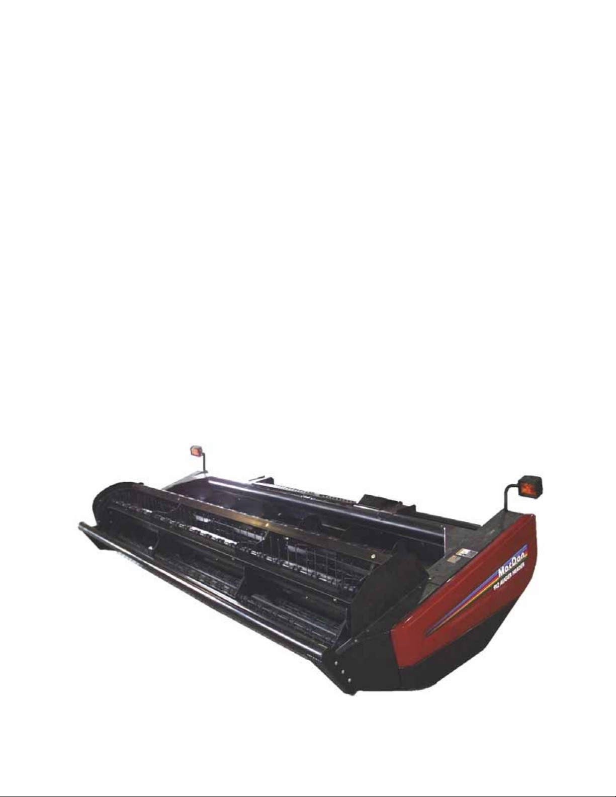
Model 912 / 922
AUGER HEADER and
Model 722
HAY CONDITIONER
Model 933
Grass Seed Special
AUGER HEADER
OPERATOR’S MANUAL
Form 46620 Issue 01/06
Sugg. Retail: $15.00
Page 2

Inside Front Cover
(blank)
Page 3
INTRODUCTION
Your new Model 912 or 922 Auger Header and 722 Hay Conditioner, teamed with the MacDon Self Propelled
Windrower power unit is designed to cut, condition, and lay in windrows, a wide variety of hay and specialty
crops. The Model 933 Grass Seed Special Header is designed specifically for the unique requirements of
growers of this crop.
The header, conditioner and power unit provides a package which incorporates many features and
improvements in design requested by Owner/Operators like yourself.
NOTE: This manual contains information on the Auger Header and Hay Conditioner. It is to be used in
conjunction with the Self-Propelled Windrower Operator's manual, which provides information on the power
unit (tractor).
CAREFULLY READ BOTH MANUALS TO BECOME FAMILIAR WITH ALL RECOMMENDED
PROCEDURES BEFORE ATTEMPTING TO UNLOAD, ASSEMBLE OR USE THE WINDROWER, OR
HEADER.
Use this manual as your first source of information about the machine. If you follow the instructions given in
this manual, your Windrower will work well for many years.
The manual contains instruction for "Safety", "Operation" and "Maintenance/Service". In addition, "Unloading
and Assembly" information is given towards the back of this book.
Use the Table of Contents and the Index to guide you to specific areas. Study the Table of Contents to
familiarize yourself with how the material is organized.
Keep this manual handy for frequent reference and to pass on to new operators or owners. Call your
Windrower dealer if you need assistance, information, or additional copies of the manuals.
NOTE: Right hand (R/H) and left hand (L/H) designations are determined from the operator's position, facing
forward.
Form # 46620 Issue 01/06
1
Page 4

TABLE OF CONTENTS
PAGE
INTRODUCTION.........................................................................................................................................1
SERIAL NUMBER LOCATIONS .................................................................................................................4
SAFETY
Safety Alert Symbol................................................................................................................................5
Signal Words..........................................................................................................................................5
Safety Signs...........................................................................................................................................6
General Farm Safety...........................................................................................................................7,8
SPECIFICATIONS
Auger Header and Hay Conditioner.......................................................................................................9
Hardware Torque Specifications..........................................................................................................10
Hydraulic Fittings Torque Specifications..............................................................................................11
OPERATION
Your Responsibilities as an Owner/Operator.......................................................................................12
To the New Operator............................................................................................................................12
Attaching the Hay Conditioner ..................................................................................................... 13 - 15
Detaching the Hay Conditioner .......................................................................................................16,17
Break-In Period ....................................................................................................................................18
Pre-Starting Checks: Annual................................................................................................................19
Pre-Starting Checks: Daily...................................................................................................................20
Operate Correctly.................................................................................................................................20
Header Controls...................................................................................................................................21
Header Lift Cylinder Stops ...................................................................................................................21
Operating Variables .............................................................................................................................22
Lean Bar Position.................................................................................................................................22
Ground Speed......................................................................................................................................23
Reel Speed ..........................................................................................................................................24
Reel Pick-Up Finger Pitch....................................................................................................................25
Cutting Height ......................................................................................................................................26
Skid Shoes ......................................................................................................................................26
Gauge Rollers .................................................................................................................................26
Header Angle .......................................................................................................................................27
Header Flotation...................................................................................................................................27
Auger Mounted Crop Deflectors/Stripper Bar Extensions/Short Spare Stripper..................................28
Hay Conditioner Roll Intermesh ...........................................................................................................29
Hay Conditioner Roll Tension Springs .................................................................................................30
Auger Feed Pan/Rock Drop Tine Position Relative to Hay Conditioner ..............................................30
Hay Conditioner Forming Shields ...................................................................................................31,32
Windrow Width ................................................................................................................................31
Rear Deflector .................................................................................................................................31
Forming Shield Height.....................................................................................................................32
Forming Shield Deflector Fins..............................................................................................................32
Haying Tips: .........................................................................................................................................33
Topsoil Moisture ..............................................................................................................................33
Climate and Topography .................................................................................................................33
Windrow Characteristics..................................................................................................................33
Raking and Tedding ........................................................................................................................33
Chemical Drying Agents..................................................................................................................33
"Grass Seed Special" Header..............................................................................................................34
Unplugging the Header ........................................................................................................................35
Hydraulic Conditioner Roll Opener..................................................................................................35
Transporting the Header ......................................................................................................................36
Lifting the Header in Working Position.........................................................................................
Storage Procedure...............................................................................................................................37
........36
Form # 46620 Issue 01/06
2
Page 5

TABLE OF CONTENTS
PAGE
MAINTENANCE/SERVICE
Service Procedures..............................................................................................................................38
Recommended Lubricants ...................................................................................................................39
Enclosed Drive Lubricant Capacities ...................................................................................................39
Sealed Bearing Installation ..................................................................................................................39
Greasing the Header and Hay Conditioner.................................................................................. 40 - 43
Sickle and Sickle Drive
Sickle Lubrication ............................................................................................................................44
Sickle Sections ................................................................................................................................44
Sickle Removal................................................................................................................................44
Head Needle Bearing Installation....................................................................................................45
Sickle Installation.............................................................................................................................45
Sickle Storage (Spare Sickle)..........................................................................................................45
Standard Sickle Guards and Hold-Downs.......................................................................................46
Stub Guards and Hold-Downs.........................................................................................................47
Hold Downs – Cast (Optional).........................................................................................................47
Double Sickle Timing.......................................................................................................................48
Changing Double Sickle Speed.......................................................................................................48
Tightening Double Sickle Drive Belts ..............................................................................................49
Tightening Single Sickle Drive Belt .................................................................................................49
Wobble Box Maintenance ...............................................................................................................50
Reel and Reel Drive
Reel Position - Fore and Aft ............................................................................................................51
Replacing Reel Fingers - 922 & 933 Headers.................................................................................52
Reel Speed - 912 Header................................................................................................................52
Reel Drive Belt Tension - 912 Header.............................................................................................52
Reel Drive Chain Tension - 922 & 933 Headers .............................................................................53
Hydraulic Reel Drive - 922 & 933 Headers .....................................................................................53
Auger and Auger Drive
Auger Position .................................................................................................................................54
Auger Speed ...................................................................................................................................55
Auger Drive Belt/Chain Tension ......................................................................................................55
Hay Conditioner
Hay Conditioner Roll Timing............................................................................................................56
Hay Conditioner Drive Belt ..............................................................................................................57
Hay Conditioner Gear Case Lubricant ............................................................................................58
Maintenance Schedule.........................................................................................................................59
Maintenance Record............................................................................................................................60
TROUBLE SHOOTING ..................................................................................................................... 61 - 65
ATTACHMENTS
Tall Crop Kit .........................................................................................................................................66
Gauge Rollers ......................................................................................................................................66
Adjustable Skid Shoes .........................................................................................................................66
Replacement Reel Bat Kits ..................................................................................................................67
Stub Guards.........................................................................................................................................67
Conditioned Windrow Side Delivery System........................................................................................67
Hydraulic Conditioner Roll Opener.......................................................................................................67
UNLOADING.............................................................................................................................................68
ASSEMBLY....................................................................................................................................... 69 - 79
INDEX .................................................................................................................................................80, 81
Form # 46620 Issue 01/06
3
Page 6
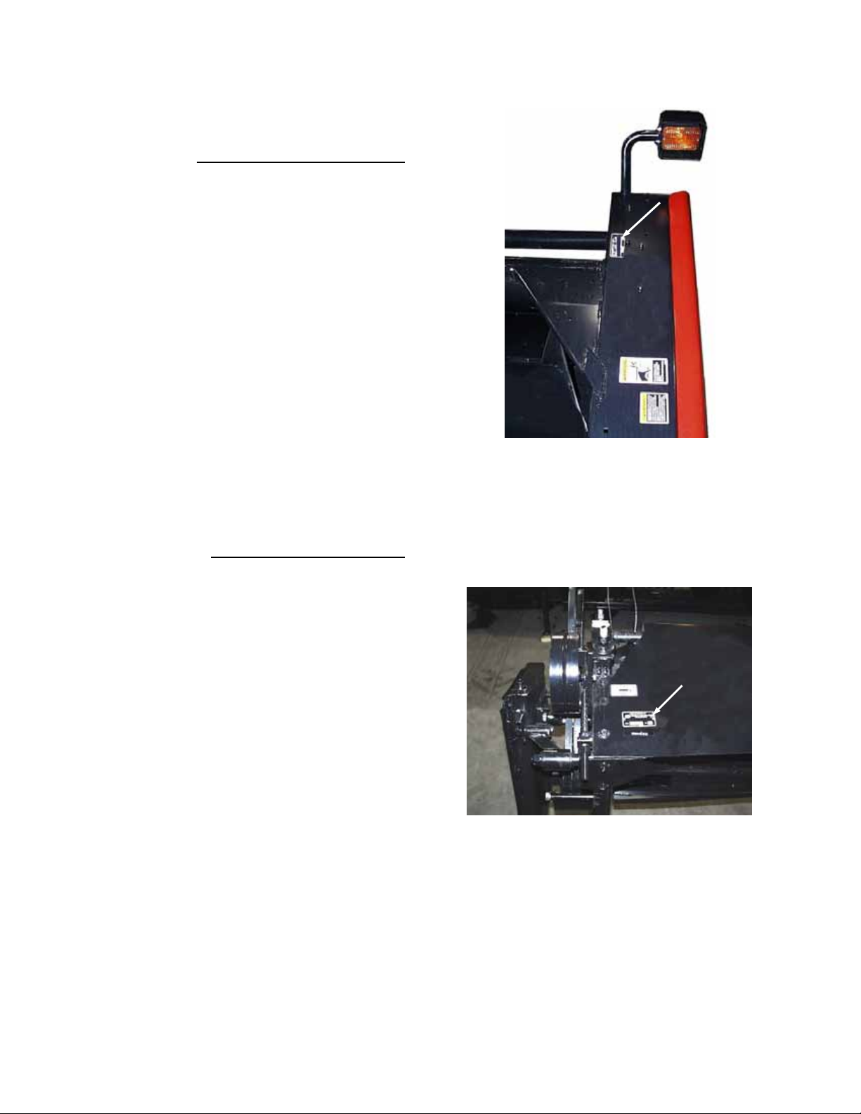
SERIAL NUMBER LOCATIONS
Record the serial numbers in the space provided.
Auger Header:
Plate is located on top of left-hand end sheet.
Hay Conditioner:
Plate is located on left side of top sheet.
NOTE: When ordering parts and service, be sure
to give your dealer the complete and proper serial
number.
AUGER HEADER SERIAL PLATE LOCATION
HAY CONDITIONER SERIAL PLATE
LOCATION
Form # 46620 Issue 01/06
4
Page 7

SAFETY
SAFETY ALERT SYMBOL
This safety alert symbol indicates important safety messages in this
manual and on safety signs on the header.
This symbol means:
ATTENTION!
BECOME ALERT!
YOUR SAFETY IS INVOLVED!
Carefully read and follow the safety message accompanying this symbol.
Why is SAFETY important to you?
· ACCIDENTS DISABLE AND KILL
3 BIG REASONS · ACCIDENTS COST
· ACCIDENTS CAN BE AVOIDED
SIGNAL WORDS
Note the use of the signal words DANGER, WARNING, and CAUTION with safety messages. The appropriate
signal word for each message has been selected using the following guidelines:
DANGER – Indicates an imminently hazardous situation that, if not avoided, will result in death or
serious injury.
WARNING – Indicates a potentially hazardous situation that, if not avoided, could result in death or
serious injury. It is also used to alert against unsafe practices.
CAUTION – Indicates a potentially hazardous situation that, if not avoided, may result in minor or
moderate injury. It is also used as a reminder of good safety practices.
Form # 46620 Issue 01/06
5
Page 8
SAFETY
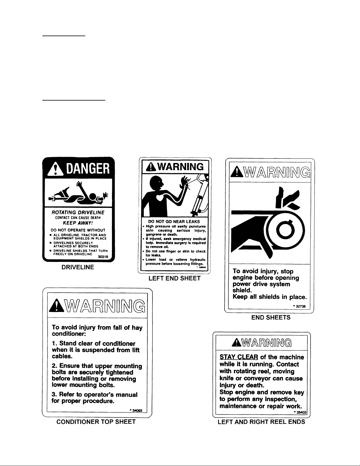
SAFETY SIGNS
· The safety signs reproduced below appear on the header at the locations listed.
· Keep safety signs clear and legible at all times.
· Replace safety signs that are missing or become illegible.
· If original parts on which a safety sign was installed are replaced, be sure the repair part also bears
the current safety sign.
· Safety signs are available from your Dealer Parts Department. The part number is printed in the
lower R/H corner of each safety sign.
To install safety signs:
1. Be sure the installation area is clean and dry.
2. Decide on the exact position before you remove the backing paper.
3. Remove the smaller portion of the split backing paper.
4. Place the sign in position and slowly peel back the remaining paper, smoothing the sign as it is
applied.
5. Small air pockets can be smoothed out or pricked with a pin.
Form # 46620 Issue 01/06
6
Page 9
SAFETY
GENERAL SAFETY
The following are general farm
safety precautions that should be
part of your operating procedure for
all types of machinery.
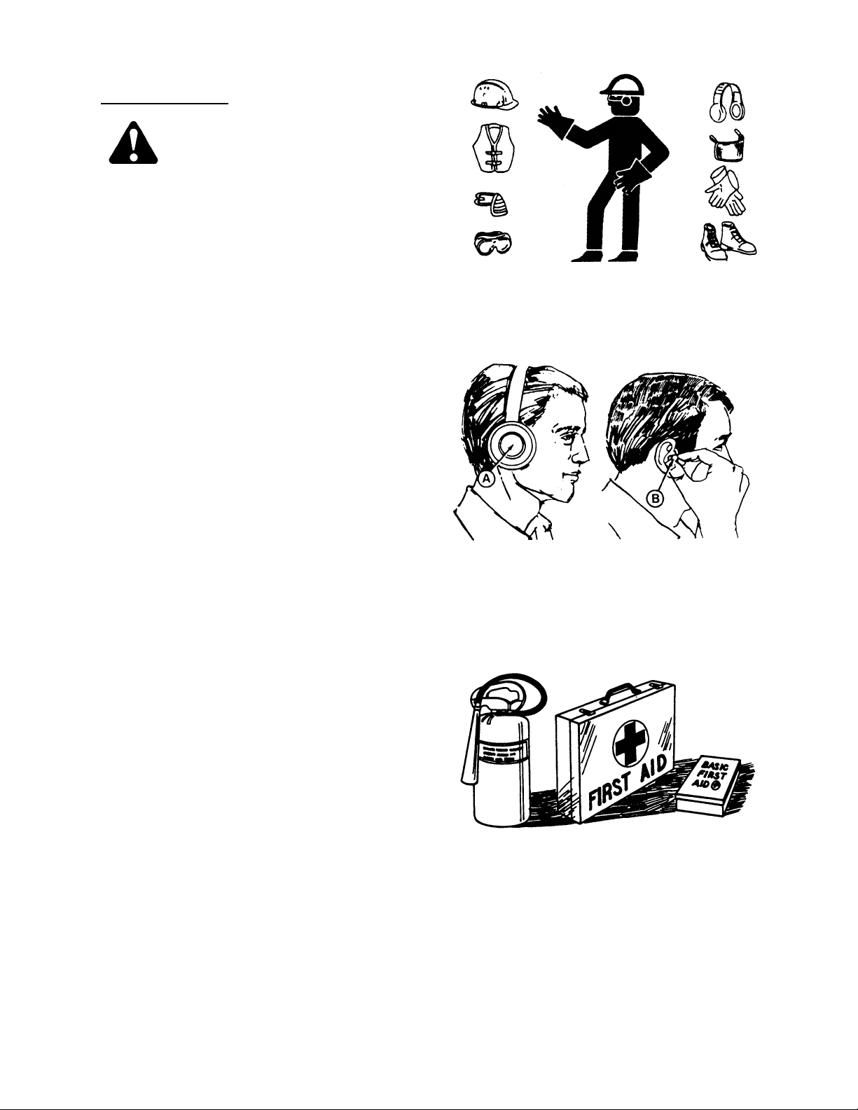
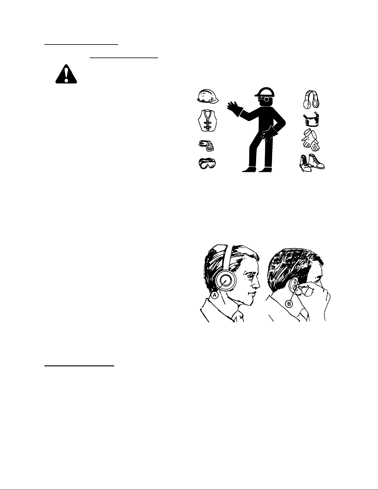
1. Protect yourself.
When assembling, operating and servicing
machinery wear all the protective clothing
and personal safety devices that COULD be
necessary for the job at hand. Don't take
chances.
You may need:
· a hard hat.
· protective shoes with slip resistant soles.
· protective glasses or goggles.
· heavy gloves.
· wet weather gear.
· respirator or filter mask.
· hearing protection. Be aware that prolonged
exposure to loud noise can cause
impairment or loss of hearing. Wearing a
suitable hearing protective device such as
earmuffs (A) or earplugs (B) protects
against objectionable or loud noises.
2. Provide a first-aid kit for use in case of
emergencies.
3. Keep a fire extinguisher on the machine. Be
sure the extinguisher is properly maintained
and be familiar with its proper use.
4. Keep young children away from machinery
at all times.
5. Be aware that accidents often happen when
the operator is tired or in a hurry to get
finished. Take the time to consider the
safest way. Never ignore warning signs of
fatigue.
PROTECT YOURSELF
PROTECT AGAINST NOISE
BE PREPARED FOR EMERGENCIES
Form # 46620 Issue 01/06
7
Page 10
SAFETY
GENERAL SAFETY
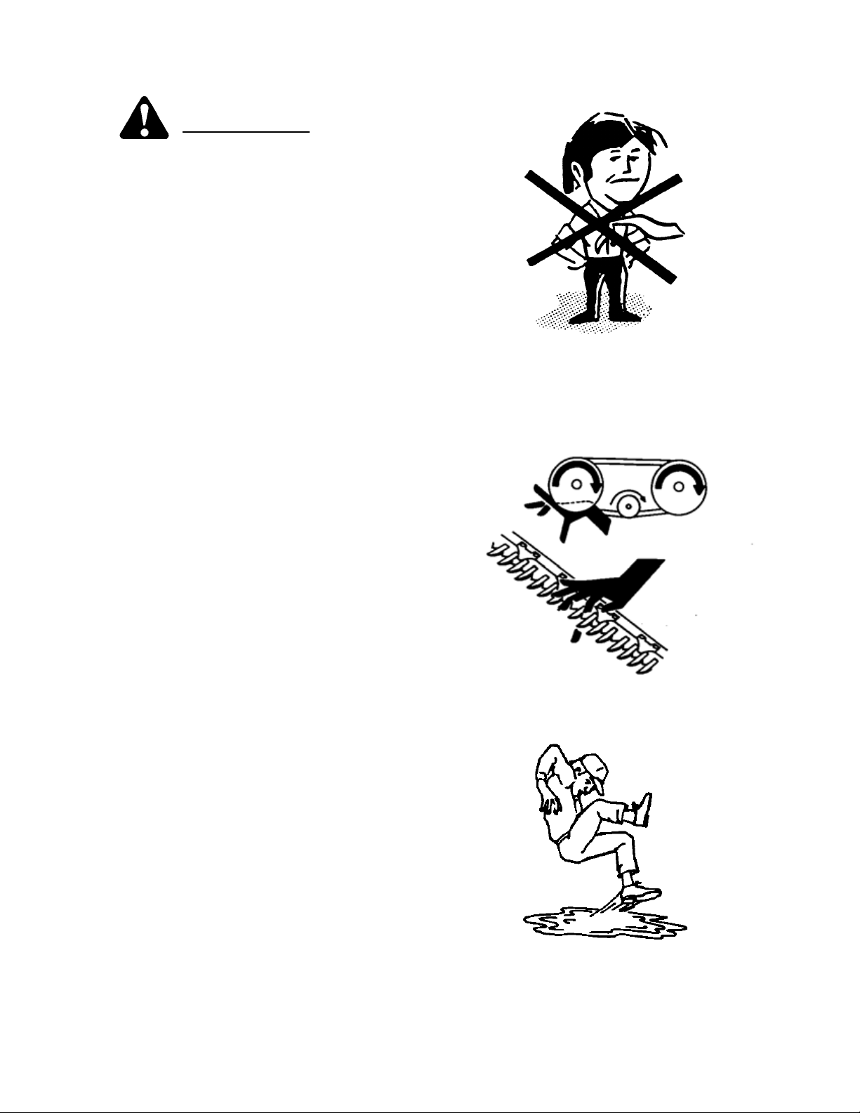
6. Wear close-fitting clothing and cover long
hair. Never wear dangling items such as
scarves or bracelets.
7. Keep hands, feet, clothing and hair away
from moving parts. Never attempt to clear
obstructions or objects from a machine
while the engine is running.
8. Keep all shields in place. Never alter or
remove safety equipment. Make sure
driveline guards can rotate independently of
the shaft and can telescope freely.
9. Use only service and repair parts made or
approved by the equipment manufacturer.
Substituted parts may not meet strength,
design, or safety requirements.
10. Do not modify the machine. Unauthorized
modifications may impair the function
and/or safety and affect machine life.
11. Stop engine and remove key from ignition
before leaving operator's seat for any
reason. A child or even a pet could engage
an idling machine.
12. Keep the area used for servicing machinery
clean and dry. Wet or oily floors are
slippery. Wet spots can be dangerous when
working with electrical equipment. Be sure
all electrical outlets and tools are properly
grounded.
13. Use adequate light for the job at hand.
14. Keep machinery clean. Straw and chaff on a
hot engine are a fire hazard. Do not allow oil
or grease to accumulate on service
platforms, ladders or controls. Clean
machines before storage.
15. Never use gasoline, naphtha or any volatile
material for cleaning purposes. These
materials may be toxic and/or flammable.
16. When storing machinery, cover sharp or
extending components to prevent injury
from accidental contact.
(continued)
KEEP SERVICE AREA CLEAN AND DRY
NEVER WEAR LOOSE
OR DANGLING CLOTHES
KEEP AWAY FROM MOVING PARTS
Form # 46620 Issue 01/06
8
Page 11

SPECIFICATIONS
AUGER HEADERS:
AVAILABLE SIZES 912 Single Sickle Header: 12 ft., 14 ft.
922 Double Sickle Header: 14 ft., 16 ft., 18 ft.
CUT WIDTHS 12' 3" (3.73 m) / 14' 3" (4.34 m) / 16' 3" (4.95 m) / 18' 3" (5.56 m)
SINGLE SICKLE DRIVE "C" belt to enclosed oil bath wobble box
DOUBLE SICKLE DRIVE Timing belts to enclosed oil bath wobble boxes
SINGLE SICKLE SPEED 1450 S.P.M.
DOUBLE SICKLE SPEED 1875* or 1450 S.P.M. (* - factory assembled)
STANDARD SICKLE TYPE Over-serrated (bolted) sections, double heat-treated guards
GRASS SEED SICKLE TYPE Fixed lower stub guards, over-serrated (bolted) sections and forged
CUTTERBAR RANGE 6 in. (150 mm) below ground to 35.5 in. (900 mm) above ground
GUARD ANGLE measured with cutterbar on ground:
Tractor models:
XX52/XX52i c/w shallow angle kit
XX52/XX52i w/o shallow angle kit
XX40/XX50
DELIVERY OPENING WIDTH 912/922 Header: 60 in. (1524 mm)
AUGER DRIVE 912 Header: "C" belt to chain final drive
AUGER SPEED 912 Header: 210 rpm standard, 186 rpm optional
AUGER TYPE 24 in. (610 mm) diameter - center feed
REEL DRIVE 912 Header: "C" belt from auger drive
REEL SPEED 912 Header: 71 rpm Standard, 63 or 80 rpm Optional
REEL TYPE 912/922 Header: 5 Bat (standard)
HEADER WEIGHT 12' 912 single sickle - 2435 lbs. (1105 kg)
722 HAY CONDITIONER:
TYPE Crimper - Intermeshing steel rolls, Header mounted
ROLL WIDTH 63.5 in. (1615 mm)
ROLL DIAMETER 8.7" (220 mm)
SPEED 850 rpm
WEIGHT 730 lbs. (330 kg)
933 Grass Seed Header (Double Sickle): 12 ft., 14 ft.
adjustable upper hold-downs
(measured to guard tip)
8° to 16° below horizontal
8° to 16° below horizontal
11° to 18° below horizontal
933 Grass Seed Header: 68, 59, or 50 in. (1720, 1490, 1260 mm)
922/933 Header: Enclosed gearbox
922 Header: 205 rpm standard, 170 rpm optional
933 Grass Seed Header: 12’ & 14’ = 170 rpm, 16’ = 205 rpm
922/933 Header: Hydraulic to chain final drive
922 Header: 30 to 75 rpm (variable from cab)
933 Grass Seed Header: 30 to 69 rpm (variable from cab)
933 Grass Seed Header: 6 bat standard
Pick-up Reel, cam action, replaceable steel fingers
14' 912 single sickle - 2644 lbs. (1199 kg)
14' 922 double sickle - 2821 lbs. (1280 kg)
16' 922 double sickle - 3114 lbs. (1410 kg)
18' 922 double sickle - 3413 lbs. (1550 kg)
12' 933 Grass Seed double sickle - 2680 lbs. (1220 kg)
14' 933 Grass Seed double sickle - 2900 lbs. (1315 kg)
16’ 933 Grass Seed double sickle – 3193 lbs (1451 kg)
Form # 46620 Issue 01/06
9
Page 12
[
[
]
[.4]
[
]
[
[
]
[4]
[7]
[7]
[11]
[18]
[26]
[37]
[52]
[66]
[92]
[
[
]
[
[
]
[
[
]
[
[
]
[
[
]
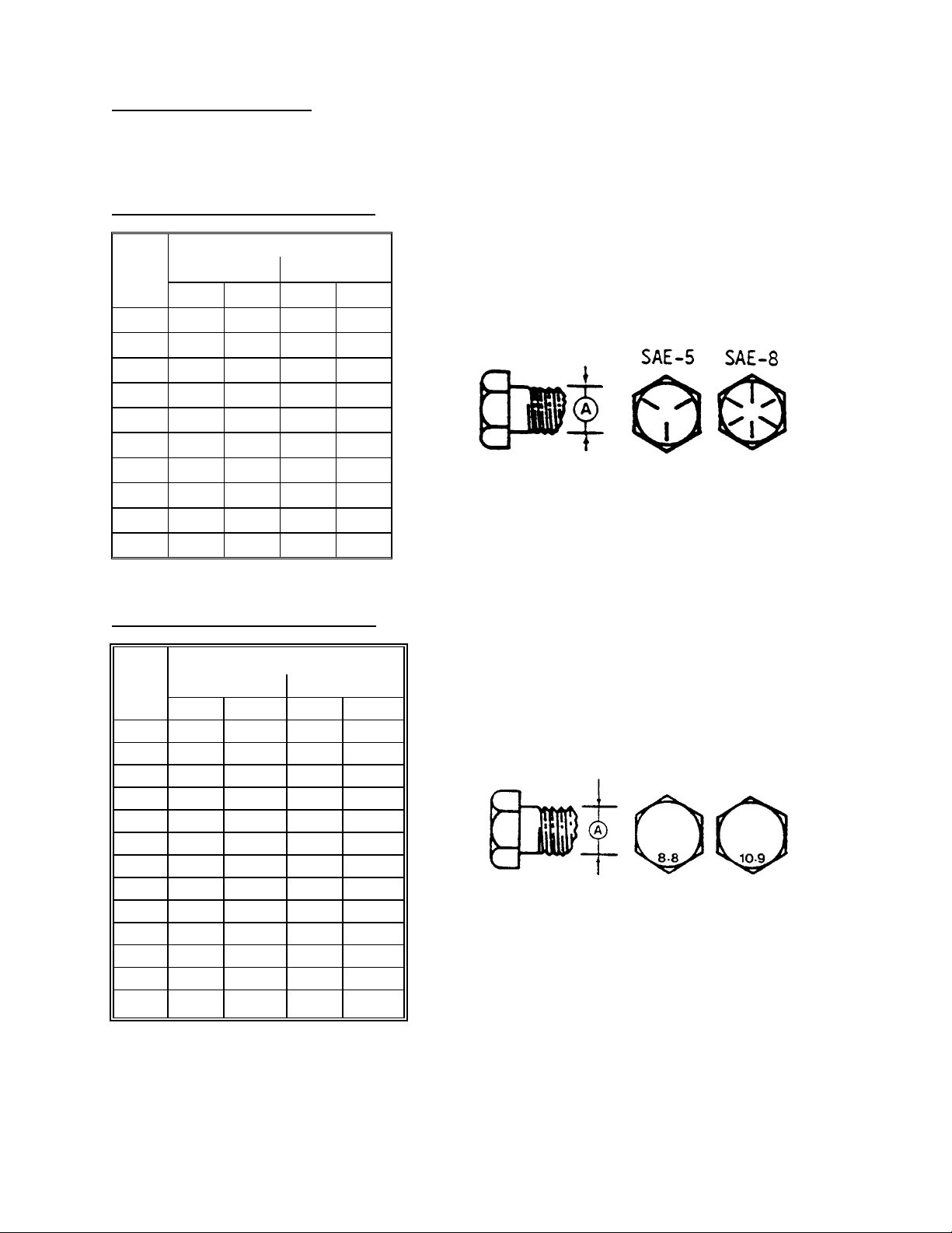
CHECKING BOLT TORQUE
TORQUE SPECIFICATIONS
The tables shown below give correct torque values for various bolts and capscrews. Tighten all bolts to the
torques specified in chart unless otherwise noted throughout this manual. Check tightness of bolts periodically,
using bolt torque chart as a guide. Replace hardware with the same strength bolt.
ENGLISH TORQUE SPECIFICATION
Bolt
Dia.
"A"
1/4" 12 [9] 15 [11]
5/16" 24 [18] 34 [25]
3/8" 43 [32] 56 [41]
7/16" 68 [50] 95 [70]
1/2" 102 [75] 142 [105]
9/16" 149 [110] 202 [149]
5/8" 203 [150] 271 [200]
3/4"
7/8" 569 [420] 813 [600]
1" 867 [640] 1205 [890]
METRIC TORQUE SPECIFICATIONS
Bolt
Dia.
"A"
M3 0.5
M4
M5
M6
M8
M10 50
M12 90
M14 140
M16 225
M20 435
M24 750
M30 1495
M36 2600 [1917] 3675 [2710]
Torque figures indicated above are valid for non-greased or non-oiled threads and heads unless otherwise
specified. Do not grease or oil bolts or capscrews unless specified in this manual. When using locking
elements, increase torque values by 5%.
* Torque value for bolts and capscrews are identified by their head markings.
NC Bolt Torque*
SAE 5 SAE 8
N·m [lb-ft] N·m [lb-ft]
359 [265]
Bolt Torque*
8.8
3
6
10
25
lb-ft] N·m
2.2] 4.5
103] 200
166] 310
321] 610
553] 1050
1103] 2100
N·m
495 [365]
1.8
9
15
35
70
125
10.9
lb-ft
1.3
3.3
148
229
450
774
1550
Form # 46620 Issue 01/06
10
Page 13

TORQUE SPECIFICATIONS
TIGHTENING HYDRAULIC O-RING FITTINGS*
1. Inspect O-ring and seat for dirt or obvious
defects.
2. On angle fittings, back the lock nut off until
washer bottoms out at top of groove.
3. Hand tighten fitting until back up washer or
washer face (if straight fitting) bottoms on face
and O-ring is seated.
4. Position angle fittings by unscrewing no more
than one turn.
5. Tighten straight fittings to torque shown.
6. Tighten angle fittings to torque shown while
holding body of fitting with a wrench.
* The torque values shown are based on
lubricated connections as in reassembly
.
Size
(in.)
Nut Size
Across
Flats
(in.)
Thread
3/8 1/2 8 [6]
7/16 9/16 12 [9]
1/2 5/8 16 [12]
9/16 11/16 24 [18]
3/4 7/8 46 [34]
7/8 1 62 [46] 1-1/2 1/4
1-1/16 1-1/4 102 [75]
1-3/16 1-3/8 122 [90]
1-5/16 1-1/2 142 [105] 3/4 1/8
Torque Value*
Recommended
Turns to Tighten
(after finger
tightening)
N·m [lb-ft] Flats Turns
2 1/3
2 1/3
2 1/3
2 1/3
2 1/3
1 1/6
1 1/6
TIGHTENING HYDRAULIC FLARE-TYPE
TUBE FITTINGS*
1. Check flare and flare seat for defects that
might cause leakage.
2. Align tube with fitting before tightening.
3. Lubricate connection and hand tighten swivel
nut until snug.
4. To prevent twisting the tube(s), use two
wrenches. Place one wrench on the connector
body and with the second tighten the swivel
nut to the torque shown.
* The torque values shown are based on
lubricated connections as in reassembly.
1-5/8 1-7/8 190 [140] 3/4 1/8
1-7/8 2-1/8 217 [160] 1/2 1/12
Tube
Size
O.D.
(in.)
Nut Size
Across
Flats
(in.)
Torque Value*
Recommended
Turns to Tighten
(after finger
tightening)
N·m [lb-ft] Flats Turns
3/16 7/16 8 [6]
1 1/6
1/4 9/16 12 [9]
1 1/6
5/16 5/8 16 [12]
1 1/6
3/8 11/16 24 [18]
1 1/6
1/2 7/8 46 [34]
1 1/6
5/8 1 62 [46]
1 1/6
3/4 1-1/4 102 [75] 3/4 1/8
7/8 1-3/8 122 [90] 3/4 1/8
Form # 46620 Issue 01/06
11
Page 14
OPERATION
YOUR RESPONSIBILITIES AS AN OWNER/OPERATOR
CAUTION:
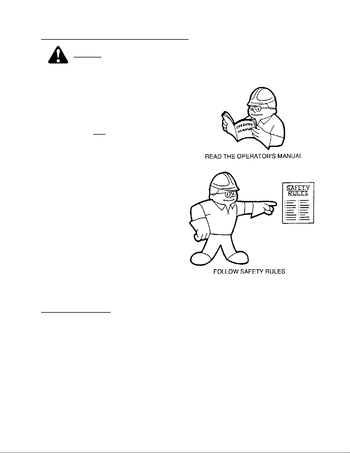
1. It is your responsibility to read and
understand this manual and the Windrower
Operator's Manual completely before
operating the header. Contact your dealer if
an instruction is not clear to you.
2. Follow all safety messages in the manual
and on safety signs on the machine.
3. Remember that YOU
Good safety practices protect you and the
people around you.
4. Before allowing anyone to operate the
machine, for however short a time or
distance, make sure they have been
instructed in its safe and proper use.
5. Review the manual and all safety related
items with all operators annually.
6. Be alert for other operators not using
recommended procedures or not following
safety precautions. Correct these mistakes
immediately, before an accident occurs.
7. Do not modify the machine. Unauthorized
modifications may impair the function
and/or safety and affect machine life.
8. The safety information given in this manual
does not replace safety codes, insurance
needs, or laws governing your area. Be sure
your machine meets the standards set by
these regulations.
TO THE NEW OPERATOR
It's natural for an operator to be anxious to get
started with a new machine. Please take the time
to familiarize yourself with the header by reading
the Operator's Manuals and safety signs before
attempting operation.
are the key to safety.
Form # 46620 Issue 01/06
12
Page 15
OPERATION
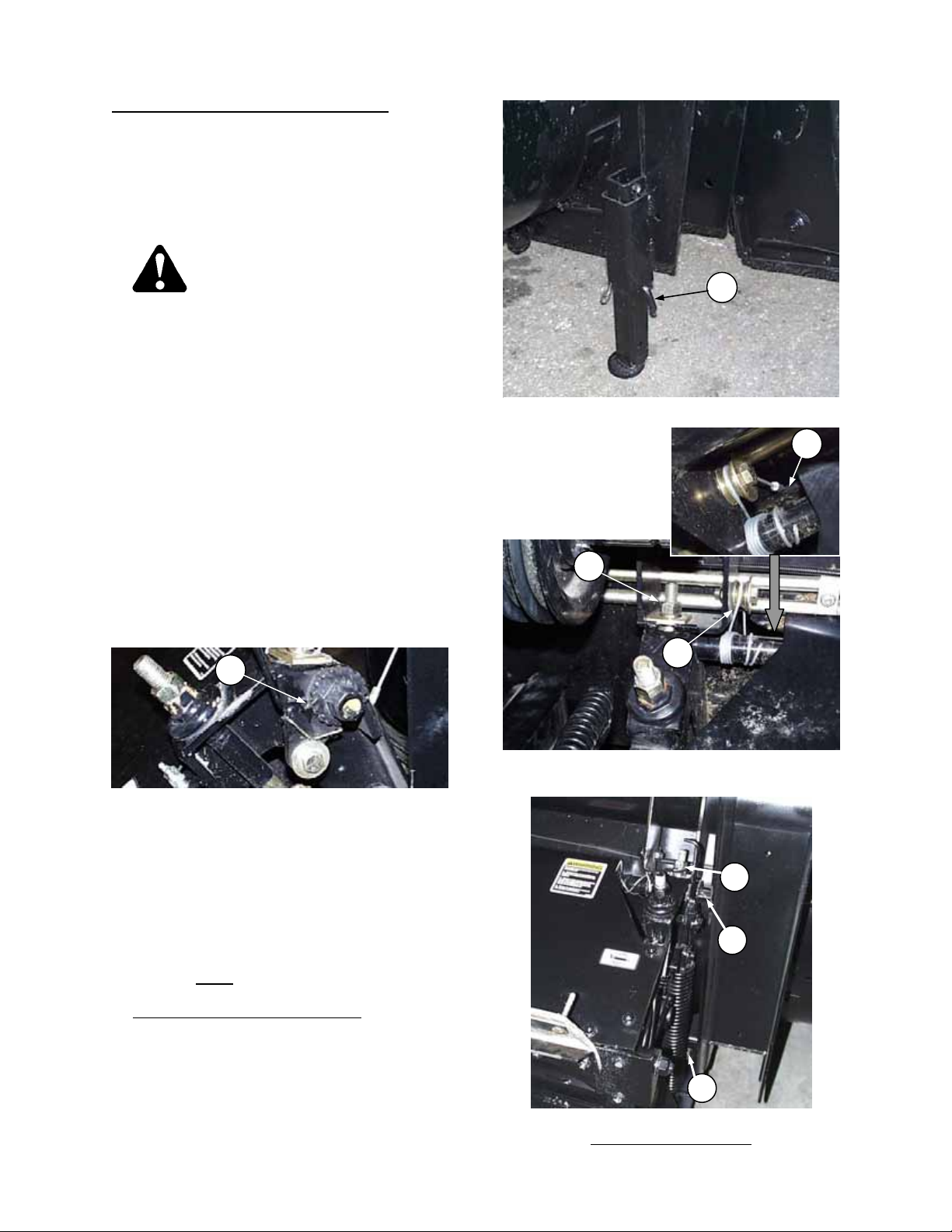
ATTACHING THE HAY CONDITIONER
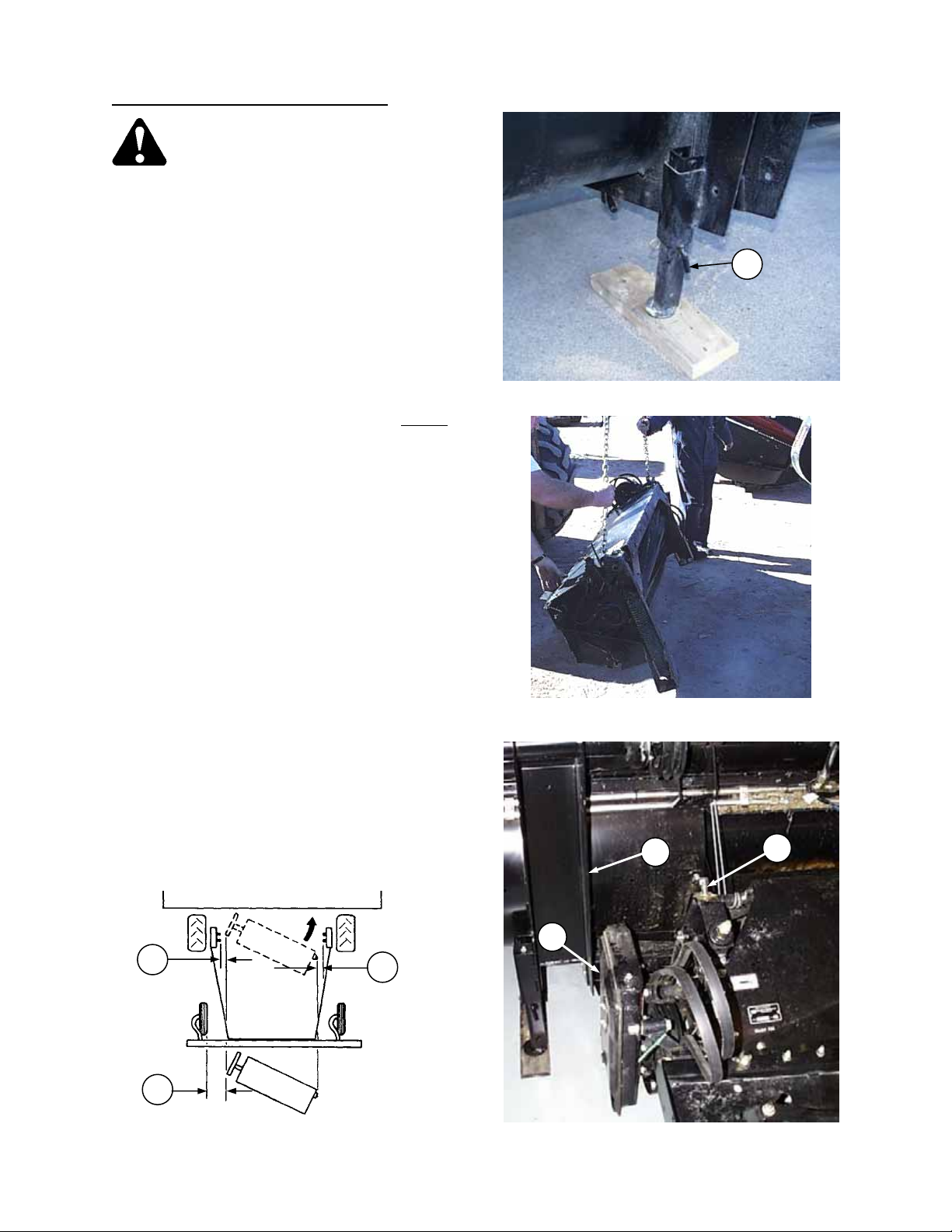
WARNING: Avoid possible injury or
death from fall of hay conditioner:
a. Be sure header stand is secure, with L-pin
(L) engaged and locked with hairpin. In soft
conditions, use a 2 x 4 block under stand.
b. Stand clear of hay conditioner whenever it
is suspended from lift cables only. Keep
hands clear of conditioner and header when
winching.
c. Be sure that upper mounting bolts are
securely tightened before installing or
removing lower mounting bolts. Hay
conditioner weighs approximately 730 lbs.
(330 kg) and will fall suddenly if lift system
becomes disengaged.
HEADER STAND – LOCKED & SECURE
IMPORTANT: For ease of installation, detach
header from tractor before attaching hay
conditioner to header. See Windrower Tractor or
Adapter Operator's Manual.
1. To move conditioner, attach chain hooks to
conditioner side frames as shown (or to U-bolt
on top sheet if present) and lift with forklift.
Position hay conditioner behind header,
approximately in center of swath opening. Be
sure mounting hardware (A) (5/8 mounting bolt,
flatwasher, lockwasher and nut) is in place on
both sides.
NOTE: Watch clearance at gear case (B) and L/H
header leg (C).
If no means of moving the conditioner is available,
use the tractor to position the header as shown
below, then detach header from tractor.
ATTACH CHAIN AT SIDE FRAMES OR U-BOLT
a. Position tractor and header in front of hay
conditioner at angle shown below.
b. Check alignment of hay conditioner with tractor
to ensure sufficient clearance at (D), (E) & (F).
c. Slowly drive tractor straight back so the hay
conditioner is positioned as shown by dotted
lines.
d. Detach header from tractor and back away.
e. Manually rotate right side of hay conditioner so
winch cables can be installed.
L
C
A
B
D
F
CHECK CLEARANCES IF POSITIONING
HEADER WITH TRACTOR
Form # 46620 Issue 01/06
E
POSITION HAY CONDITIONER
FOR INSTALLATION
13
Page 16
OPERATION
ATTACHING THE HAY CONDITIONER
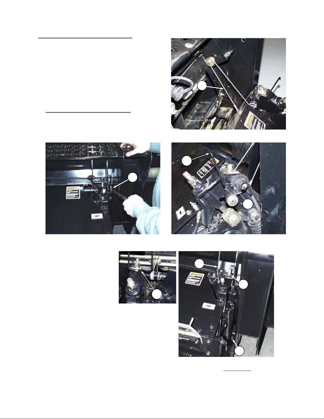
2. Attach winch cables (G) both sides.
NOTE: Ensure cable is correctly routed over pulley
as shown, not crossing over.
3. Standing clear of the hay conditioner
inch wrench on winch nut (H). Keeping hands clear
of conditioner, pull wrench upward to raise the
conditioner into position. After each upward pull on
wrench, push lever (A) forward to ensure winch
pawl engages ratchet wheel at (B).
RAISE HAY CONDITIONER WITH WINCH
4. As hay conditioner reaches
mounted position, slide top
mounting bolts (J) into
header mounting brackets
(K) with square washer, lock
washer and hex nut on top.
NOTE: On left side, be sure
square washer is captured
behind welded stop (C) on
mounting bracket, not resting
on top.
5. TIGHTEN BOLTS (J), BOTH SIDES, SECURELY
BEFORE PROCEEDING TO STEP 6. Use winch
to take up any slack in cables once bolts (J) are
tight.
6. Install and tighten lower mounting bolts (L). (5/8 x
1-1/2 carriage bolt [head to rear], flat washer, lock
washer and hex nut.
(continued)
, use a 1-1/8
H
C
G
ATTACH WINCH CABLES
A
B
ENSURE WINCH PAWL ENGAGES WHEEL
K
J
L
INSTALL AND TIGHTEN MOUNTING
BOLTS – TOP FIRST
Form # 46620 Issue 01/06
14
Page 17
OPERATION
S
ATTACHING THE HAY CONDITIONER
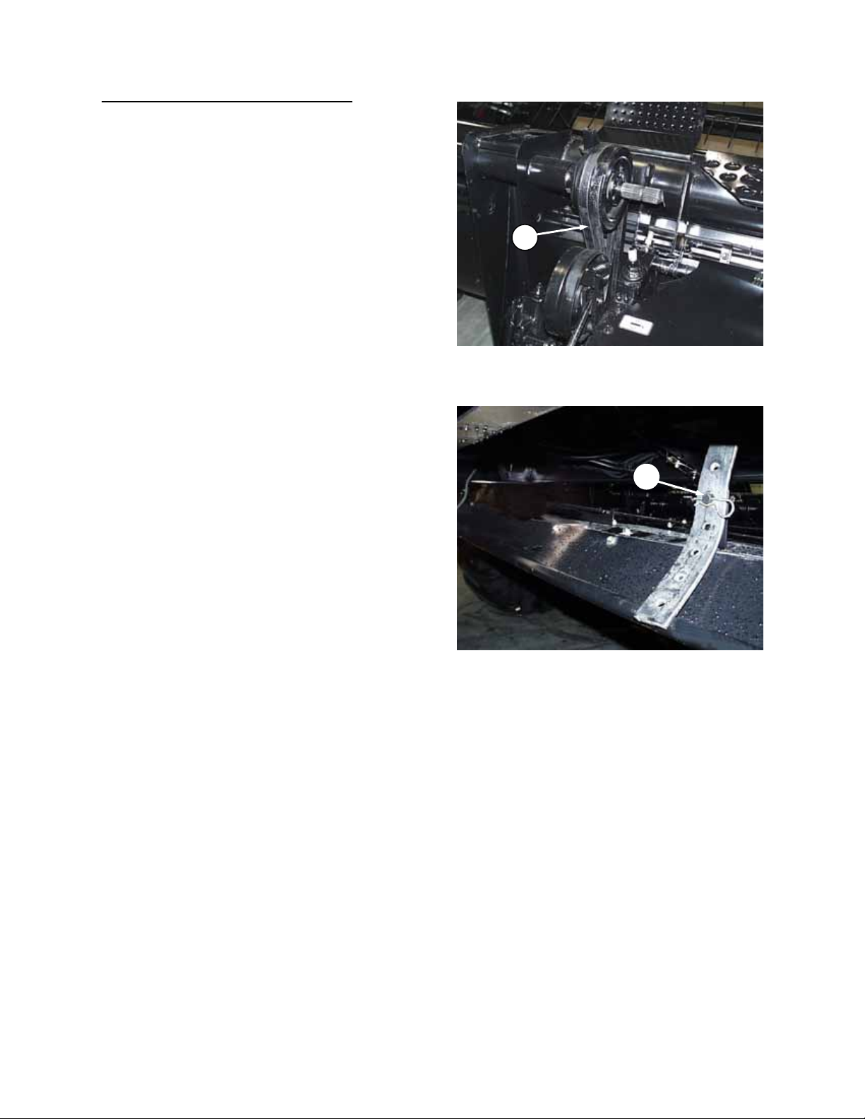
7. Install belt over pulley (M) on header drive
shaft. *
NOTE: Do not pry belt over pulley. Loosen or
remove spring-loaded idler to allow installation.
(If idler is removed, take note of hardware
positioning for re-assembly.)
* IMPORTANT: Before first use, position drive
pulley (M) on shaft to align the belt. See
"Attaching the Hay Conditioner" in Assembly
section.
8. Adjust belt tension. See "Hay Conditioner Drive
Belt" in Maintenance/Service section.
9. Attach header to tractor. See Windrower
Tractor or Adapter Operator's manual.
10. Attach forming shield rear support straps to
lower brackets at (N).
NOTE: See Assembly section for instruction
regarding attaching forming shields to
conditioner and/or tractor.
11. Adjust header float springs for additional
weight. See Windrower Tractor or Adapter
Operator's manual.
(continued)
M
INSTALL BELT AND ADJUST TENSION
N
ATTACH FORMING SHIELD REAR SUPPORT
Form # 46620 Issue 01/06
15
Page 18
OPERATION
DETACHING THE HAY CONDITIONER
1. For ease of removal, first detach the header
from the tractor. See Windrower Tractor or
Adapter Operator's Manual.
NOTE: If front of conditioner forming shield is
attached to conditioner, remember to detach
rear support straps at lower brackets.
WARNING: Avoid possible injury
or death from fall of hay
conditioner:
a. Be sure header stand is secure, with L-pin
(L) engaged and locked with hairpin. In soft
conditions, use a 2 x 4 block under stand.
b. Be sure that upper mounting bolts (F) are
securely tightened before installing or
removing lower mounting bolts. Hay
conditioner weighs approximately 730 lbs.
(330 kg) and will fall suddenly if lift system
becomes disengaged.
c. Check that winch cables are:
• properly routed over pulleys (D)
• tightly wrapped around winch tube
• secured at hook (A) on front face of
conditioner
• If necessary, take up cable slack by
pulling up on 1-1/8 inch wrench on winch
nut (E).
d. Check that winch pawl is engaged in ratchet
wheel at (B).
B
HEADER STAND – LOCKED & SECURE
L
A
F
D
CABLES TIGHT AND PROPERLY ROUTED
& TOP MOUNTING BOLTS TIGHT
e. Stand clear of hay conditioner whenever it
is suspended from lift cables only. Keep
hands clear of conditioner and header when
winching.
F
2. Loosen idler adjuster and remove drive belt
from header pulley. See "Hay Conditioner Drive
Belt" in Maintenance/Service section for
adjuster details.
E
3. Remove lower
conditioner mounting bolts (C).
4. Standing clear of hay conditioner
, loosen and
disengage top mounting bolts (F) from brackets
on header.
C
REMOVE MOUNTING BOLTS -
LOWER BOLTS FIRST
Form # 46620 Issue 01/06
16
Page 19
OPERATION
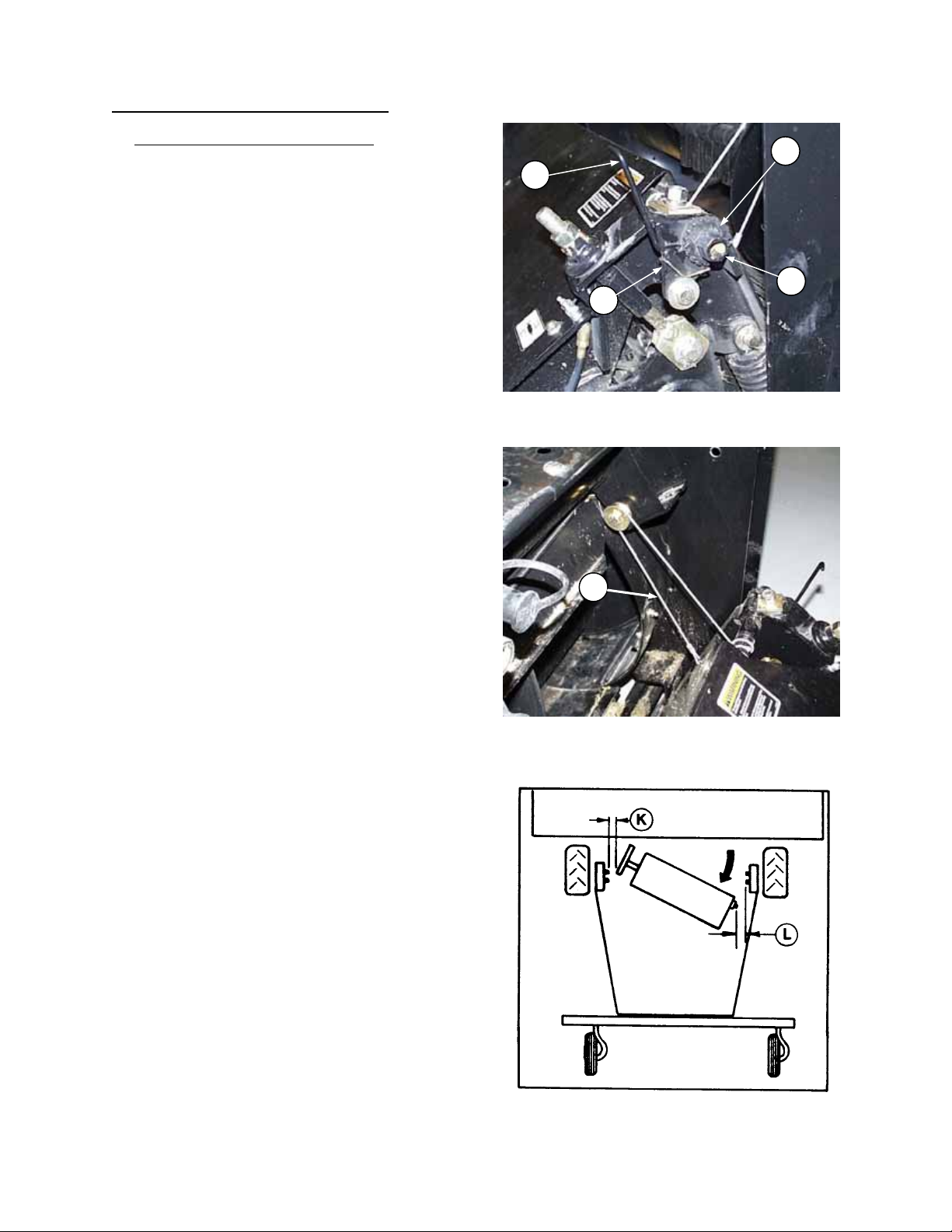
DETACHING THE HAY CONDITIONER
5. Standing clear of hay conditioner
follows. Use a long wrench and keep hands
clear of conditioner and header when winching.
a. Position a 1-1/8 wrench on winch nut (E) and
pull firmly up. Pull lever (G) back to disengage
winch pawl (H) from ratchet wheel (J).
b. Turn winch nut (E) down as far as possible and
push lever (G) forward, ensuring winch pawl
(H) engages ratchet wheel (J).
c. Remove and reposition the wrench on the
winch nut and repeat steps 5a and 5b until the
conditioner is on the ground and winch cables
(D) are slack.
6. Detach winch cables (D) from pulleys on
header.
7. When attaching header to tractor:
If no means of moving the conditioner away
from the header is available, manually rotate
right side of hay conditioner as shown to
maximize clearance. Be sure that there is
sufficient clearance to hydraulic lines at (K) and
(L).
(continued)
, lower as
J
G
E
H
LOWER CONDITIONER WITH WINCH
D
DETACH WINCH CABLES
ROTATE CONDITIONER FOR CLEARANCE
IF ATTACHING HEADER TO TRACTOR
Form # 46620 Issue 01/06
17
Page 20

OPERATION
BREAK-IN PERIOD
1. After attaching header to windrower tractor for
the first time, operate the machine slowly for 5
minutes, watching and listening FROM THE
OPERATOR'S SEAT for binding or interfering
parts.
CAUTION: Before investigating an
unusual sound or attempting to
correct a problem; shut off engine,
engage park brake and remove key.
2. Check all belts after 5 hours
stretch. Tighten as necessary. (See
Maintenance/Service section.
Continue to check the belts periodically for the
first 50 hours.
3. Tighten any loose hardware after 5 hours
operation. See Specifications section for
recommended torque’s.
4. Tighten the bottom and side wobble box
mounting bolts (C) after 10 hours
and every 100 hours thereafter. Torque to 200
ft.lbs. (270 N⋅m), starting with the side
mounting bolts.
5. Change wobble box lubricant after 50 hours
operation and every 1000 hours (or 3 years)
thereafter. See Maintenance/Service section.
6. Until you become familiar with the sound and
feel of your new header, be extra alert and
attentive.
operation for initial
operation
TIGHTEN WOBBLE BOX MOUNTING BOLTS
Form # 46620 Issue 01/06
18
Page 21

OPERATION
PRE-STARTING CHECKS
Do the following at the start of each operating
season.
1. Review the Operator’s Manual to refresh
2. Review all safety signs and other decals on
3. Be sure all shields and guards are properly
4. Reaquaint yourself with the controls before
Also:
5. Adjust tension on all belts and chains. See
6. Perform all annual maintenance. See
CAUTION:
your memory on safety and operating
recommendations.
the machine and note hazard areas.
installed and secured. Never alter or
remove safety equipment.
beginning operation.
Maintenance/Service section.
Maintenance/Service section.
Form # 46620 Issue 01/06
19
Page 22
OPERATION
PRE-STARTING CHECKS
Do the following each day before start-up:
CAUTION:
1. Clear the area of other persons, pets, etc.
Keep children away from machinery. Walk
around the header to be sure no one is under,
on or close to it.
2. Remove foreign objects from the machine and
surrounding area.
3. Wear close fitting clothing and protective
shoes with slip resistant soles.
As well, carry with you any protective clothing
and personal safety devices that COULD be
necessary through the day. Don’t take
chances.
You may need:
- a hard hat
- protective glasses or goggles
- heavy gloves
- respirator or filter mask
- wet weather gear
4. Protect against noise. Wear suitable hearing
protective devices such as (A) earmuffs or ear
plugs (B) to protect against objectionable or
uncomfortable loud noise.
5. Check the machine for leaks or any parts that
are missing, broken, or not working correctly.
Use proper procedure when searching for
pressurized fluid leaks. See “Hydraulic Reel
Drive” in Maintenance/Service section.
6. Clean lights and reflectors on the header.
7. Perform all daily maintenance. See
Maintenance/Service section.
OPERATE CORRECTLY
IMPORTANT: See Windrower Operator’s
Manual for information on the following:
Start-Up Procedure
Driving the Windrower
Stopping Procedure
Form # 46620 Issue 01/06
20
PROTECT YOURSELF
PROTECT AGAINST NOISE
Page 23
OPERATION
HEADER CONTROLS
CAUTION: Be sure all bystanders are
clear of machine before starting
windrower or engaging any header
drives.
See the Windrower Tractor Operator's Manual for
identification of in-cab controls for:
• Header Drive Clutch
• Header Height
• Ground Speed
• Reel Speed
• Hydraulic Conditioner Roll Opener (Option)
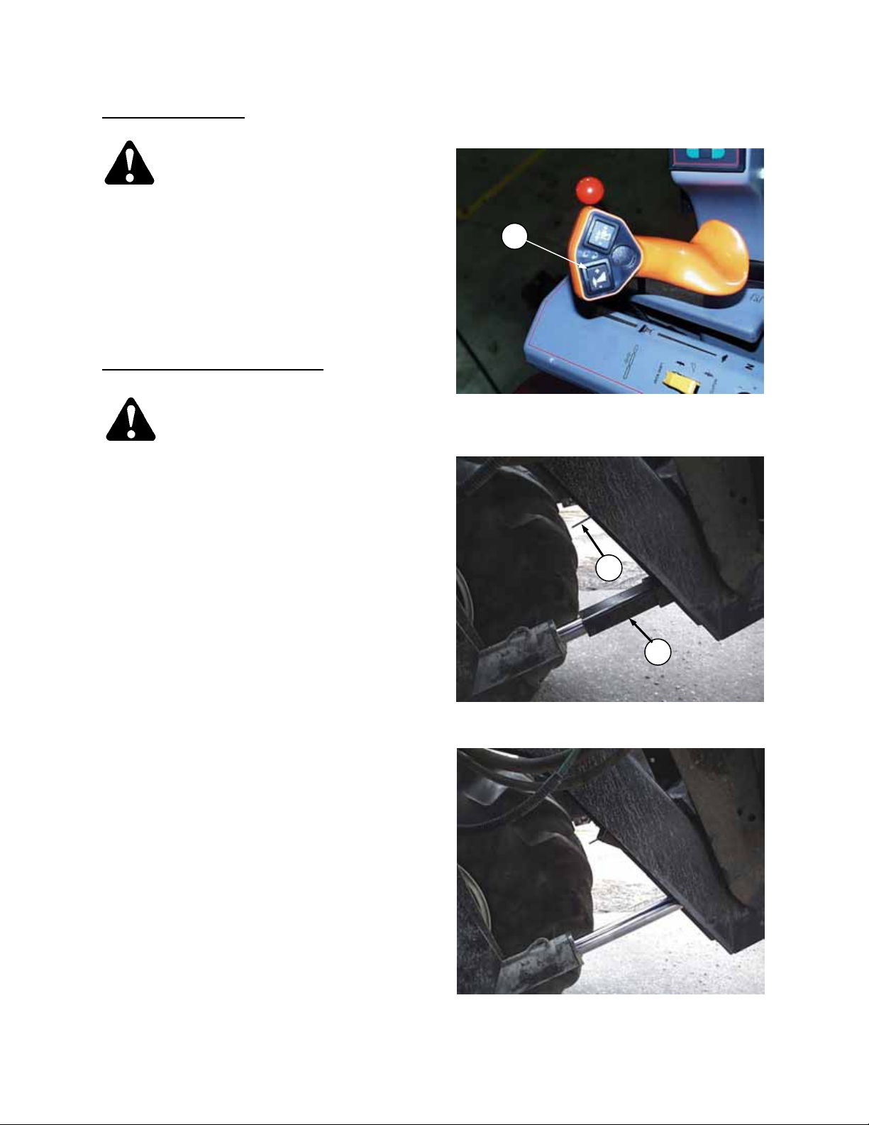
HEADER LIFT CYLINDER STOPS
DANGER: To avoid bodily injury or
death from fall of raised header,
always engage cylinder stops before
going under header for any reason.
Cylinder stops are located on both header lift
cylinders on windrower.
To engage cylinder stops:
1. Press top of header height switch (A) to raise
header to maximum height.
2. Lift retainer (B) up to release cylinder stop (C).
Lower stop onto cylinder.
3. To store, push up on stop (C) until retainer
locks in storage position.
A
HEADER HEIGHT SWITCH
B
C
LIFT CYLINDER STOP - ENGAGED
LIFT CYLINDER STOP - STORAGE
Form # 46620 Issue 01/06
21
Page 24
OPERATION
A
OPERATING VARIABLES
Satisfactory function of the header and hay
conditioner in all situations requires making proper
adjustments to suit various crops and conditions.
Correct operation reduces crop loss and allows
cutting of more acres. As well, proper adjustments
and timely maintenance will increase the length of
service you receive from the machine.
The variables listed here and detailed on the
following pages will affect the performance of the
header and conditioner. You will quickly become
adept at adjusting the machine to give you the
desired results.
LEAN BAR POSITION
IMPORTANT: To prevent structural damage to
header, do not operate with lean bar removed.
Use the lean bar adjustment to accommodate
different crop heights.
The lean bar should strike the upper portion of
crop, leaning it away from the header and
exposing the stalks to the sickle.
To raise or lower lean bar, re-position hardware
(A) in adjustment holes as required.
NOTE: In very tall crops, to prevent pinning of crop
around lean bar, extensions are available. See
“Tall Crop Kit” in Attachments section.
UGER HEADER
1. Lean Bar Position
2. Ground Speed
3. Reel Speed
4. Reel Pick-Up Finger Pitch
5. Cutting Height
6. Header Angle
7. Header Flotation
8. Auger Mounted Crop Deflectors
HAY CONDITIONER
9. Roll Intermesh
10. Roll Tension
11. Feed Pan Position
12. Forming Shields
OPERATING VARIABLES
LEAN BAR ADJUSTMENT
A
Form # 46620 Issue 01/06
22
Page 25
OPERATION
GROUND SPEED
Ground speed of windrower should be such that
sickle can cut crop smoothly and cleanly.
See Windrower Tractor Operator's Manual for
identification and instructions for use of ground
speed control.
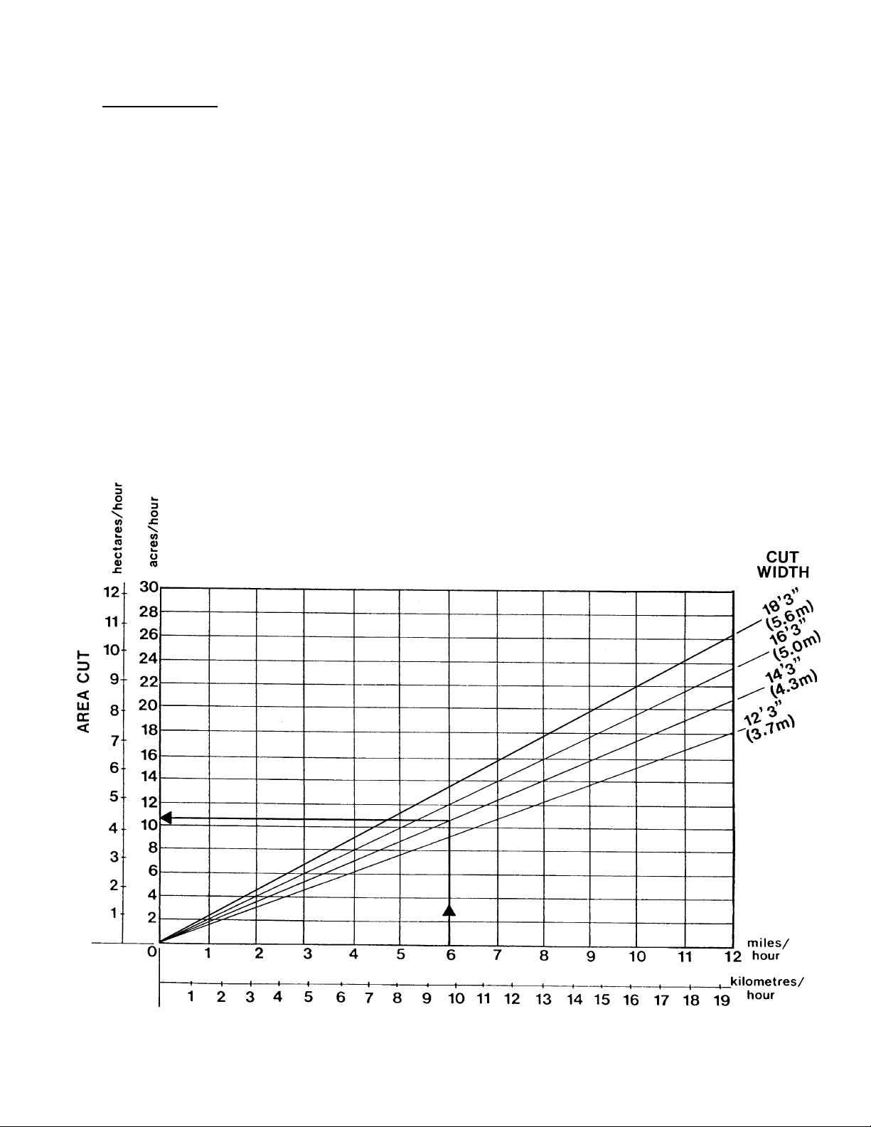
The chart below indicates the relationship between
ground speed and area cut for the three auger
header sizes.
Example shown: At a ground speed of 6 miles per
hour (9.7 km/h) with a 14 ft. header*, the area cut
per hour would be 10-1/2 to 11 acres (4-1/4 to
4-1/2 hectares).
* A 14 ft. header has a cut width of 14 ft. 3 in. (4.3 m)
A 12 ft. header has a cut width of 12 ft. 3 in. (3.7 m)
A 16 ft. header has a cut width of 16 ft. 3 in. (5.0 m)
An 18 ft header has a cut width of 18 ft. 3 in. (5.6 m)
Form # 46620 Issue 01/06
23
Page 26

OPERATION
REEL SPEED
For best feeding of crop into the sickle and auger,
reel speed should be just faster than ground
speed. This gently sweeps crop across sickle into
auger. Excessive reel speed causes undue wear
of reel components and unnecessary load on reel
drive, resulting in uneven reel motion.
922 and 933 Headers
See Windrower Tractor Operator's Manual for
identification and instructions for use of reel speed
control in cab.
NOTE: Both speed control knobs on tractor
console are used to adjust reel speed.
912 Header
See "Reel and Reel Drive" in Maintenance/
Service section for instructions regarding changing
reel speed.
Form # 46620 Issue 01/06
24
Page 27

OPERATION
REEL PICK-UP FINGER PITCH
Another factor in effective feeding of crop into the
sickle and auger is finger pitch angle (the angle the
fingers operate at in relation to the ground).
NOTE: In the illustration at right, pitch angle (A) is
more aggressive than pitch angle (B).
Generally it should not be necessary to adjust the
finger pitch angle, however in certain crop types
and conditions adjustment of the finger pitch may
be required to achieve best results.
The pitch should be just aggressive enough to
provide adequate crop lifting action for proper
cutting.
Pitch angle can be adjusted by rotating the cam.
Rotating the cam forward
results in a more aggressive
Rotating the cam rearward
results in a less aggressive
To adjust cam position
1. Loosen four bolts (C), both ends of reel.
2. Turn bolts (D) at cam end to move cam up or
down at front or rear until desired position is
obtained.
3. Tighten four bolts (C), both ends, to secure
reel position.
4. Rotate reel slowly by hand and check finger
clearance at knife and pan. Flex fingers to
simulate crop-loaded position to ensure
fingertip clearances to knife sections and
auger pan are adequate for working
conditions.
5. If necessary, adjust reel fore-aft position to
achieve proper clearances. See Maintenance/
Service section.
NOTE: For optimum header performance in all
crops, position the reel so that finger tips are as
close as possible to knife sections and auger
pan without interfering. Some contact between
finger tips and knife guards is acceptable.
Rotate tines in direction of crop load, to check
for minimum clearance as tines pass over
guards and pan.
(higher in the back),
pitch angle.
(higher in the front),
pitch angle.
:
FINGER PITCH ANGLE
FINGER PITCH ADJUSTMENT
CHECK TINE CLEARANCE
Form # 46620 Issue 01/06
25
Page 28

OPERATION
CUTTING HEIGHT
Your header will be equipped with either:
• wide adjustable outer skid shoes, or
• gauge rollers plus narrower skid shoes.
Vary the cutting height by adjusting either skid
shoe or gauge roller position. The operator can
then lower the header to the ground, allowing the
shoes or rollers to provide a consistent cutting
height.
NOTE: Lowering the skid shoes or gauge rollers
raises the cutting height. (Gauge rollers allow
higher settings than skid shoes.) This may be
desirable in stony conditions, to reduce damage to
cutting components. Other benefits include
reduced plugging due to mud or dirt build-up and
longer stubble for faster drying.
WARNING: To avoid bodily injury or
death from unexpected start-up or
fall of raised header; stop engine,
remove key and engage header lift cylinder
stops before going under header to adjust skid
shoes or gauge rollers (or for any reason).
Skid Shoes
The right and left end skid shoes are adjustable up
and down.
To adjust:
1. Remove pins (A), two per shoe.
2. Move shoe up or down to desired position and
replace pins (A).
Gauge Rollers
To adjust gauge roller height:
1. Remove pins (B), two per wheel.
2. Move roller to desired position and replace
pins (B).
LIFT CYLINDER STOP - ENGAGED
A
SKID SHOE ADJUSTMENT
B
GAUGE ROLLER ADJUSTMENT
Form # 46620 Issue 01/06
26
Page 29

OPERATION
HEADER ANGLE
The header (or guard) angle is adjustable in the following range depending on tractor model (measured with
cutterbar on ground):
Tractor models:
XX52/XX52i c/w shallow angle kit
XX52/XX52i w/o shallow angle kit
XX40/XX50
8° to 16° below horizontal
8° to 16° below horizontal
11° to 18° below horizontal
Header angle is adjusted by lengthening or shortening the tractor lift linkage center link. Choose an angle that
maximizes performance for your crop and field conditions.
IMPORTANT: A flatter header angle is recommended for normal conditions. A flatter angle reduces sickle
section breakage and reduces soil build-up at the cutterbar and/or auger pans in wet conditions or where
ground is uneven (gopher mounds, etc.).
Use a steeper angle to cut very close to the ground, or for better lifting action of down crops.
See Windrower Tractor Operator's Manual for adjustment procedure.
HEADER FLOTATION
As a starting point for normal conditions, adjust float spring tension so that 75 - 85 lbs. force (335 to 380 N) is
required to lift cutterbar off ground at each end.
Benefits of lighter float settings:
1. Less cutting component breakage in rough or stony conditions.
2. Avoids soil build-up at the cutterbar and/or auger pans in wet conditions or where ground is uneven
(gopher mounds, etc.).
Benefits of heavier float settings:
1. When cutting very close to the ground, enables cutterbar to closely follow ground contours.
Header float weight changes if lift linkage center link length is changed. Float weight also varies through
first few inches of header lift cylinder extension. Check header float weight after selecting a center link
length and with header lift cylinders fully retracted. Readjust header float springs if necessary to obtain
desired float. See Windrower Tractor Operator's Manual for adjustment procedure.
Form # 46620 Issue 01/06
27
Page 30

OPERATION
AUGER MOUNTED CROP DEFLECTORS/STRIPPERS & STRIPPER BAR EXTENSIONS:
912 & 922 HEADERS
Four rubber finger assemblies are mounted to the auger to direct crop rearward to the hay conditioner such
that material is evenly distributed across the full width of the conditioner. If too much “end feeding” of
conditioner rolls is occurring, remove two outboard rubber finger assemblies (A).
If too much “Center Feeding” of conditioner rolls is occurring, the following may be necessary:
1. Install flighting-mounted deflectors (B). Deflectors are stored under platform at (C). Depending on crop
conditions, install one or two deflectors at each side of delivery opening.
2. Replace full-length front “L” angle strippers with 1/2 length front “C” channel strippers. These 1/2 length
strippers are stored on underside of pan at (D). On-header storage of full length front strippers is not
provided.
3. Remove center stripper extensions (E) on center stripper bars at each side of delivery opening.
AUGER MOUNTED CROP DEFLECTORS
B
C
AUGER FLIGHTING DEFLECTOR
E
CENTER STRIPPER EXTENSIONS
D
FRONT STRIPPER – SHORTER “C” CHANNEL
DEFLECTOR STORAGE
STRIPPER STORAGE
Form # 46620 Issue 01/06
28
Page 31

OPERATION
(
)
HAY CONDITIONER ROLL INTERMESH
The intermeshing steel rolls of the hay conditioner
crimp the plant stems in several places, allowing
moisture release and faster drying. The degree to
which the stems are conditioned (crimped)
depends on the amount of roll intermesh.
Correct conditioning of alfalfa, clover and other
legumes is usually indicated when 90% of the
stems show crimping but no more than 5% of the
leaves are damaged. To achieve this, roll
intermesh is factory set so that dimension (D) is
approximately 5/8 inch (16 mm) for normal
operation, which corresponds to 2.5 on the roll gap
decal.
In heavy thick stemmed crops, rolls may need to
be adjusted for almost no roll intermesh (7 on roll
gap decal).
In lighter crops, a closer intermesh may be
required for optimum conditioning, however setting
rolls too close may cause excessive stem and leaf
damage.
To adjust roll intermesh
NOTE: The top face of nut (E) is used as the
indicator for the gauge decal on the threaded rod.
Each division on the roll gap decal represents a
change of approximately 1/8 inch (3mm) in roll
gap. The factory setting of 5/8 inch (16mm)-roll
gap is mark 2.5 on the decal. When adjusting roll
gap, be sure that the decal reading is the same on
both sides of the conditioner roll to achieve
consistent intermesh across the rolls.
1. Loosen nut (E).
2. Turn nut (F) clockwise to decrease intermesh,
or counter-clockwise to increase intermesh.
NOTE: Nut (F) is welded to adjuster tube so
complete assembly will turn.
3. When intermesh is correct, tighten nut (E)
while holding nut (F) with another wrench to
lock the position securely.
:
ROLL INTERMESH ADJUSTMENT
ROLL INTERMESH
FACTORY SET AT 5/8”
E
F
16 mm
ROLL INTERMESH ADJUSTMENT
Form # 46620 Issue 01/06
29
Page 32

HAY CONDITIONER ROLL TENSION SPRINGS
The conditioner roll intermesh is maintained by two
tension springs to provide roll pressure for correct
conditioning of the crop. These springs also allow
the rolls to open to allow passage of small solid
objects without damage to the rolls. The roll
tension has been factory set for normal operating
conditions and generally does not require
adjustment.
In some conditions, less aggressive conditioning
may be desirable, and roll tension can be reduced
as required. For smooth conditioner operation,
back off tension only as much as required for
desired conditioning action.
To decrease spring tension:
1. Loosen jam nut (A).
2. Turn bolt (H) out of spring to decrease tension
(easier to force rolls open.)
3. Hold spring plug (K) with a wrench and tighten
nut (A) securely against plug to secure the
position.
4. Repeat at other side.
FEED PAN/ROCK DROP TINE POSITION:
(Relative to Hay Conditioner)
Rock drop tines must be correctly positioned to
ensure proper feeding into hay conditioner. Check
also that conditioner feed pan has not become
pushed down or buckled. A damaged feed pan
can result in uneven feeding to the hay
conditioner.
To adjust position of feed pan and rock drop tines:
1. Ensure that all tine points are in line. Bend
tines to align if required.
2. Select desired setting for tine positions (see
step 4).
3. To adjust tine position, loosen bolts (J) at both
sides of delivery opening.
4. Rotate channel assembly with wrench either
upward or downward to align pointer (E) with
the center of slots in hay conditioner frame for
your specific crop conditions, as follows:
SLOT: (B) – recommended for light crop.
(C) – factory set, for medium volume crops.
(D) – recommended for heavy crop.
5. Tighten bolts (J).
Form # 46620 Issue 01/06
30
ROLL TENSION ADJUSTMENT
J
ROCK DROP TINE POSITIONING
E
ALIGN POINTER WITH CENTER OF SLOT
B
C
D
OPERATION
Page 33

OPERATION
HAY CONDITIONER FORMING SHIELDS
CAUTION: Keep forming shields installed at all times conditioner is in use. Do not allow
anyone to stand behind the machine while operating. Stones or other foreign objects may be
ejected from the conditioner with considerable force.
The side and rear deflectors, and deflector fins are adjustable to shape the windrow to your preference.
In deciding on windrow width, the following factors should be considered:
• weather conditions (rain, sun, humidity, wind)
• type and yield of crop
• drying time available
• method of processing (bales, silage, "green-feed")
A wider windrow will generally dry faster and more evenly, resulting in less protein loss. Fast drying is
especially important in areas where the weather allows only a few days to cut and bale. See "Haying Tips" in
this section for more information.
Where weather conditions permit or when drying is not critical, for example, when cutting for silage or "greenfeed", a narrower windrow may be preferred for ease of pick-up.
Windrow Width
Position the adjuster handle as required to move
the side deflectors to the desired width.
NOTE: With hardware installed in hole (A) in L/H
link as shown, deflectors will move symmetrically
about the center of the conditioner rolls. For the
most evenly formed windrows, use position (A)
for windrows up to 65 inches wide. Use hole (B)
only when windrows over 65 inches are required,
as this allows the left deflector to open to a wider
position than the right deflector. Maximum width
is with hardware in hole (B) and handle in
position (1).
Rear Deflector
The rear deflector (L) slows the crop exiting the
conditioner rolls, directs the flow downward,
and "fluffs" the material.
To start, adjust rear deflector to approximately
the mid-range position (45°). Optimum position
for best windrow uniformity must be determined
for each crop condition.
To adjust rear deflector, loosen adjuster handles
(M), one per side, position deflector and tighten
adjuster handles (M). For even windrow formation,
be sure deflector is not twisted.
HAY CONDITIONER FORMING SHIELDS
Form # 46620 Issue 01/06
31
Page 34

HAY CONDITIONER FORMING SHIELDS
(continued)
Forming Shield Height
Depending on the amount of crop material,
the rear of the forming shield assembly can
be raised or lowered to properly deflect the
crop. For heavier crops use the higher
settings:
• XX40 & XX50 series tractors use 4
th
hole from the bottom on the rubber
5
strap.
• XX52/XX52i tractors use 1
st
or 2nd hole
th
or
from the bottom of rubber strap.
For lighter crops, lower forming shield as
required to form the most uniform windrows.
Note that too low a setting will cause
uneven and poorly formed windrows.
To adjust forming shield rear height, remove
hairpin at (N), both sides, and raise or lower
shields to desired height.
NOTE: For normal operation, front of
forming shield assembly is attached to
conditioner top cover. If desired, shield
assembly can be fully tractor mounted with
front of shield assembly attached to top rear
pin of tractor lift linkage. This
accommodates frequent removal of header
from tractor. See Assembly section for details.
Deflector Fins
Four deflector fins provided standard are stored at (K) on the top L/H side of the top cover. Additional fin
hardware required is stored at (J).
Use deflector fins as shown at (D) to evenly distribute material when laying swaths wider than 72 inches (1830
mm). Fin position can be adjusted without loosening mounting bolt. Set fins approximately parallel to side
deflectors for wide swath and adjust as required for even distribution of crop across full width. For narrow
windrow less than 72 inches (1830 mm) remove fins.
NOTE: Four additional fins (available from your dealer) may be mounted in holes (A) for even crop distribution
in swaths over 90 inches (2286 mm) wide.
HAY CONDITIONER FORMING SHIELDS
OPERATION
DEFLECTOR FINS
Form # 46620 Issue 01/06
32
Page 35

OPERATION
HAYING TIPS
There is one certainty when making hay - a fast cure will maintain top quality. It is critical to have the cured hay
baled as quickly as possible, for two reasons:
1. Every day hay lies on the ground, 5% of the protein is lost.
2. The sooner the cut hay is off, the earlier the start for next growth.
Generally, leaving the windrow as wide and thin as possible makes for the quickest curing, however there are
other factors that affect curing time:
1. TOPSOIL MOISTURE
When the ground is wetter than the hay, moisture from the soil is absorbed by the hay above it. Determine
topsoil moisture level before cutting. Use a moisture tester or estimate level:
Over 45% - WET - Soil will be muddy
25 - 45% - DAMP - Walking on soil leaves tracks
Under 25% - DRY - Soil will be dusty on top
When ground is wet due to irrigation, wait until soil moisture drops below 45%. When ground is wet due to
frequent rains, cut when weather allows and let the forage lie on wet ground until it dries to the moisture level
of the ground. At this point, the cut hay will dry no more until the ground under it dries, so consider moving the
windrow to drier ground.
On wet soil, the general rule of "wide and thin" does not apply. A narrower windrow will dry faster than hay left
flat on wet ground.
2. CLIMATE AND TOPOGRAPHY
a. Try to have as much hay cut as possible by midday, when drying conditions are best.
b. Fields sloping south get up to 100% more exposure to the sun's heat than do north sloping fields. If you
bale and chop, consider baling the south facing fields and chopping those facing north.
c. When relative humidity is high, the evaporation rate is low and hay dries slower. If there is no wind,
saturated air becomes trapped around the windrow, further hindering the drying process. Raking or
tedding will expose the hay to fresher, less saturated air. Cutting hay perpendicular to the direction of the
prevailing winds may also help.
3. WINDROW CHARACTERISTICS
See "Operating Variables" in this section. Control the factors listed to produce a windrow with the following
characteristics:
a. High and fluffy for good air flow.
process than direct sunlight.
b. Consistent formation, not bunchy.
chopper etc.
c. Even distribution, not piled in the middle or higher on one side.
side could cause stacks to lean, round bales to have one end smaller and loose, or small square bales to
be heavy on one side, causing handling and stacking problems.
d. Properly conditioned without excessive leaf damage.
4. RAKING AND TEDDING
Raking or tedding will speed up drying, however the benefits must be weighted against the additional leaf
losses which will result. When the ground beneath the down hay is dry, raking or tedding is probably not
worthwhile.
Big windrows on damp or wet ground should be turned over when they reach 40-50% moisture. Hay should
not be raked or tedded at less than 25% moisture, or excessive yield losses will result.
5. CHEMICAL DRYING AGENTS
Hay drying agents work by removing wax from legume surfaces, enabling water to escape and evaporate
faster. However, treated hay lying on wet ground will also absorb ground moisture faster.
Before deciding to use a drying agent, costs and benefits relative to your area should be carefully compared.
Always follow chemical manufacturer’s recommendations for safe handling and proper use.
The movement of air through the windrow is more important to the curing
A uniform windrow permits an even flow of material into the baler,
A windrow that is higher or heavier on one
Form # 46620 Issue 01/06
33
Page 36

OPERATION
S
JUS
"GRASS SEED SPECIAL" HEADER
The grass seed auger header has several features
to adapt it to this special application. These
features include:
Stub Guards and Hold-downs
equipped with stub guards for effective cutting in
tough grass crops. See "Sickle and Sickle Drive"
in Maintenance/Service section for maintenance of
these components.
Special Auger Design
beater supports have been removed to reduce
auger wrapping.
Slower Auger Speed
slower auger speed of 170 RPM (compared with
205 RPM for 16’ and standard header) also
reduces auger wrapping.
Adjustable Stripper Bars
stripper bars are adjustable for more effective
stripping of grass crops.
To adjust:
1. Loosen bolts (G) along upper stripper bars.
2. Slide extension bars (H) in or out to obtain
approximately 1/8 inch (3 mm) clearance to
auger flighting (J) along entire auger length.
3. Tighten bolts (G).
Auger Pan Extensions
provided to reduce delivery opening from the
maximum 68 inches (1720 mm) to 59 inches (1490
mm). A second pan extension may be ordered to
further reduce opening to 50 inches (1260 mm).
NOTE: When installing auger pan extensions (A):
1. The pan supplied is factory assembled to be
installed on the left side of the delivery
opening, with cutterbar support (D) at inboard
side. Install hardware supplied as shown.
2. Move the two upper sets of stripper bars (B)
so end of stripper is flush with edge of pan
extension. The lowest (most forward) set of
stripper bars (C) should remain in standard
pan position as shown. Reset upper stripper
bars clearance as described above.
Windrow Forming Rods
provided to assist in forming the narrow windrows
preferred for this application. Bend the rods to
modify the windrow shape. Use the forming rods in
conjunction with the auger pan extensions to
achieve the width and shape of windrows you
desire. See “forming rod installation” section.
Six-Bat Reel
for smoother reel action and better crop feed into
the header.
: A sixth bat is added to the reel body,
: The center beaters and
: For 12’ & 14’ Headers, the
: One pan extension is
: The cutterbar is
: The two upper sets of
: Forming rods are
J
G
H
TRIPPER BAR AD
INSTALLING AUGER PAN
EXTENSION
POSITION UPPER STRIPPER BARS
FLUSH WITH PAN EXTENSIONS
WINDROW FORMING RODS
TMENT
Form # 46620 Issue 01/06
34
Page 37

OPERATION
UNPLUGGING THE HEADER
WARNING: Stop engine and remove
key from ignition before removing
plugged material from header.
If the sickle plugs
:
1. Stop forward movement of the windrower and
disengage header drive clutch.
2. With header on ground, back up several feet
and engage header drive clutch.
3. If plug does not clear, disengage header drive
clutch and raise header fully.
4. Shut off engine, remove key and engage park
brake.
5. Engage header lift cylinder stops.
WARNING: Wear heavy gloves when
working around sickle.
6. Clean off cutterbar.
If plugging persists, see Trouble Shooting section.
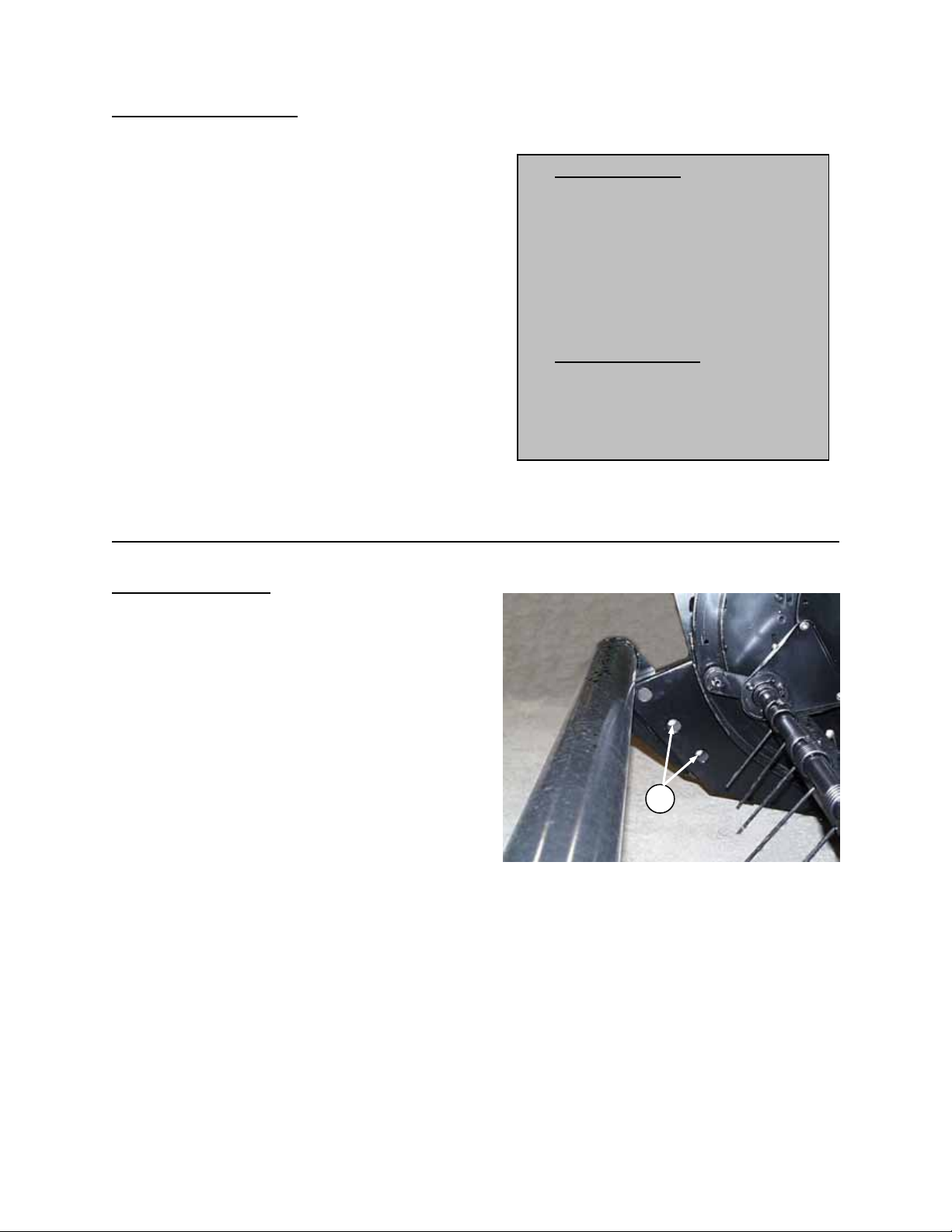
If auger or conditioner plugs:
1. Stop forward movement of the windrower,
disengage header drive clutch and raise
header fully.
2. Shut off engine, remove key and engage park
brake.
3. Engage header lift cylinder stops.
WARNING: Wear heavy gloves when
working around sickle.
4. Clean off cutterbar and area under reel.
5. Position wrench (A) over end of drive shaft (B)
and rotate counter-clockwise (from left end)
until plug clears.
6. Store wrench in left end divider and secure
with hairpin at (C).
If plugging persists, see Trouble Shooting section.
Hydraulic Conditioner Roll Opener (Option)
For units equipped with this option, if conditioner
rolls plug during operation:
• Disengage header drives.
• Press top of switch (D) to extend the cylinders
at the sides of the conditioner frame, forcing
the rolls open.
• While holding switch (D) in the up position, set
engine throttle at half speed and engage
header drive to clear conditioner plug.
• When plug is cleared, release switch and
continue normal operation. Cylinders will
automatically retract.
For information on ordering this option, see
Attachments section in this book.
running, or if header drive is engaged with
engine running. If it becomes necessary to
manually remove a plug from the conditioner:
• Disengage header drive.
• Press top of switch (D) to extend the
• Shut off engine and remove key.
• Remove plug manually and continue
A
B
CLEARING PLUGS
C
WRENCH STORAGE
D
OPERATE HYDRAULIC ROLL OPENER
WITH REEL LIFT SWITCH
WARNING: Be aware that rolls will
close automatically if bottom of
switch (D) is pressed while engine is
cylinders at the sides of the conditioner
frame, forcing the rolls open.
normal operation.
Form # 46620 Issue 01/06
35
Page 38

OPERATION
TRANSPORTING THE HEADER
See "Transporting the Windrower" in Windrower Tractor Operator's Manual for recommended procedures for:
· Driving the Windrower on Roads
· Towing the Windrower on a Trailer
· Towing the Windrower without a Trailer
NOTE: For headers with divider rods, when transporting on a side-mount trailer, remove divider rods to narrow
the transport width.
LIFTING HEADER IN WORKING POSITION
If it is necessary to lift header once it has been lowered from shipping position to working position, see "Lifting
Vehicle Requirements" and "Chain Requirements" in Unloading & Assembly section before proceeding.
Attach one chain (C) from lifting vehicle to both ends of lean bar. Attach a second chain (D) from lifting vehicle
to center link anchor on frame tube as shown.
CAUTION: Be sure hooks are secure before lifting header. Stand clear when lifting, as
machine may swing.
LIFTING HEADER IN WORKING POSITION
Form # 46620 Issue 01/06
36
Page 39

OPERATION
STORAGE PROCEDURE
Do the following at the end of each operating season:
CAUTION:
1. Clean the windrower thoroughly. Never use gasoline, naphtha or any volatile material for cleaning
purposes. These materials may be toxic and/or flammable.
2. Store machine in a dry, protected place if possible.
3. Cover cutterbar and sickle guards to prevent injury from accidental contact.
Also:
4. Repaint all worn or chipped painted surfaces to prevent rust.
5. Loosen all drive belts.
6. Lubricate the windrower thoroughly, leaving excess grease on fittings to keep moisture out of bearing.
Apply grease to exposed threads and sliding surfaces of components.
7. Check for worn or broken components and repair or order replacements from your dealer. Attention to
these items right away will save time and effort at beginning of next season.
8. Tighten loose hardware and replace any missing hardware. See Specification section for torque charts.
9. Remove divider rods (if equipped) to reduce space required for inside storage.
10. Units with stub guards - To prevent stub guard adjuster bar bolts from becoming seized, apply penetrating
oil at bolts prior to storage.
Form # 46620 Issue 01/06
37
Page 40

MAINTENANCE/SERVICE
SERVICE PROCEDURES
CAUTION: To avoid personal injury,
before servicing machine or opening
drive covers:
1. Fully lower header. If necessary to service
in the raised position, first engage header
lift cylinder stops.
2. Disengage header drive clutch.
3. Stop engine and remove key.
4. Engage park brake.
5. Wait for all
Wear close-fitting clothing and cover long hair.
Never wear dangling items such as scarves or
bracelets.
Wear protective shoes with slip-resistant soles,
a hard hat, protective glasses or goggles and
heavy gloves.
If more than one person is servicing the
machine at the same time, be aware that
rotating a driveline or other mechanically
driven component by hand (for example to
access a lube fitting) will cause drive
components in other areas (belts, pulleys and
sickle) to move. Stay clear of drive components
at all times.
Be prepared if an accident should occur. Know
where the first aid kit and fire extinguishers are
located and how to use them.
Keep the service area clean and dry. Wet or
oily floors are slippery. Wet spots can be
dangerous when working with electrical
equipment. Be sure all electrical outlets and
tools are properly grounded.
Use adequate light for the job at hand.
Replace all shields removed or opened for
service.
Use only service and repair parts made or
approved by the equipment manufacturer.
Substituted parts may not meet strength,
design or safety requirements.
Keep the machine clean. Never use gasoline,
naphtha or any volatile material for cleaning
purposes. These materials may be toxic and/or
flammable.
moving parts to stop.
Form # 46620 Issue 01/06
38
Page 41

MAINTENANCE/SERVICE
RECOMMENDED LUBRICANTS
GREASE
Use SAE Multi-Purpose High Temperature Grease with Extreme Pressure (EP) Performance and
containing at least 1.5% molybdenum disulphide. (NLGI Grade 2)
Also acceptable is an SAE Multi-Purpose Lithium Base Grease.
GEAR LUBRICANT
Wobble Box and Hay Conditioner Gear Case: Use SAE 85W-140 gear lube (API Service Class. GL-5)
Auger Drive Gear Case: Use grease as specified above.
CAPACITIES
Wobble Box – 2.2 litres (2.3 U.S. quarts)
Hay Conditioner Gear Case - 1100 ml (1.2 U.S. quart)
Auger Drive Gear Case - 600 grams (1.5 tubes)
STORING LUBRICANTS
Your machine can operate at top efficiency only if clean lubricants are used. Use clean containers to
handle all lubricants. Store them in an area protected from dust, moisture and other contaminants.
SEALED BEARING INSTALLATION
1. Clean shaft and coat with rust preventative.
2. Install flangette, bearing, flangette and lock
collar. The locking cam is only on one side of
the bearing.
3. Install (but do not tighten) the flangette bolts.
4. When the shaft is located correctly, lock the
lock collar with a punch. The collar should be
locked in the same direction the shaft rotates.
Tighten the setscrew in the collar.
5. Tighten the flangette bolts.
6. Loosen the flangette bolts on the mating
bearing one turn and re-tighten. This will allow
the bearing to line up.
TIGHTEN COLLAR IN DIRECTION
Form # 46620 Issue 01/06
39
Page 42

MAINTENANCE/SERVICE
GREASING THE HEADER AND CONDITIONER
See "Recommended Lubricants" in this section for
recommended greases.
The following greasing points are marked on the
header by decals showing a grease gun (A), and
grease interval (B) in hours of operation. Use the
hour meter in the windrower cab and the
"Maintenance Checklist" provided to keep a record
of scheduled maintenance.
Procedure:
1. Wipe grease fitting with a clean cloth before
greasing, to avoid injecting dirt and grit.
2. Inject grease through fitting with grease gun
until grease overflows fitting, except where
noted. Inject grease slowly to prevent seal
damage.
3. Leave excess grease on fitting to keep out dirt.
4. Replace any loose or broken fittings
immediately.
5. If fitting will not take grease, remove and clean
thoroughly. Also clean lubricant passageway.
Replace fitting if necessary.
10 Hours or Daily
1. Cross-Shaft Center Support Bearing (D)
- one fitting on Double Sickle Header
25 Hours
1. Sickle Head (C) - single sickle: one fitting
NOTE: If more than 6 to 8 pumps of the grease
gun are required to fill the cavity, replace the seal
in the sickle head. When changing seal, check pin
and needle bearing for wear. Replace if necessary.
See page 45.
:
- double sickle: two fittings
SAMPLE GREASE DECAL
CROSS-SHAFT CENTER SUPPORT BEARING
DOUBLE SICKLE HEADER
D
C
SICKLE HEAD
Form # 46620 Issue 01/06
40
Page 43

MAINTENANCE/SERVICE
GREASING THE HEADER AND CONDITIONER (continued)
50 Hours
:
1. Reel Finger Tube Bearings (E)
- twenty fittings on 14’, 16’, 18’ - 922 headers.
- eighteen fittings on 12’ – 933 headers.
- twenty-four fittings on 14’ – 933 headers.
3. Hay Conditioner Idler Pivot (J)
- one fitting
E
REEL FINGER TUBE BEARINGS
922 & 933 HEADERS
2. Hay Conditioner Roll Shaft Bearings (F) & (G)
- four fittings.
G
F
J
CONDITIONER IDLER PIVOT
4. Auger Drive Jackshaft Bearings (K)
- one fitting on 912 Header only
K
JACKSHAFT BEARINGS - 912 HEADER
LEFT SIDE RIGHT SIDE
CONDITIONER ROLL BEARINGS
Form # 46620 Issue 01/06
41
Page 44

CO
MAINTENANCE/SERVICE
GREASING THE HEADER AND CONDITIONER
(continued)
100 Hours or Annually:
1. Hay Conditioner Universal Shaft (H)
- three fittings.
2. Drive Shaft Support Bearings (C) &
(D)
- two fittings
3. Cross-Shaft End Support Bearings
(E) & (F)
- two fittings on Double Sickle
Header
4. Reel Shaft Bearings (G) & (H)
- two fittings on 922 and 933
Headers
LEFT END RIGHT END
DRIVE SHAFT SUPPORT BEARINGS
E
LEFT END RIGHT END
CROSS-SHAFT END SUPPORT BEARINGS
DOUBLE SICKLE HEADER
NDITIONER UNIVERSAL SHAFT
C
G
H
D
F
H
LEFT END RIGHT END
REEL SHAFT BEARINGS & DRIVE CHAIN
922 & 933 HEADERS
Form # 46620 Issue 01/06
42
Page 45

MAINTENANCE/SERVICE
GREASING THE HEADER AND CONDITIONER (continued)
100 Hours or Annually
5. Reel Drive Chain (J)
- one fitting on 922 and 933 Headers. (Four to six pumps of
grease gun will be sufficient.)
6. Reel Shaft Bearings (K) and (M)
- two fittings on 912 Header
7. Auger Shaft Bearing (L) and (P)
- one fitting
8. Gauge Roller Bearings (N) - (Optional Equipment)
- four fittings
L
912 HEADER 922/933 HEADERS
K
LEFT END RIGHT END
REEL SHAFT BEARINGS - 912
J
REEL DRIVE CHAIN
M
P
AUGER SHAFT BEARING
N
GAUGE ROLLER BEARINGS
Form # 46620 Issue 01/06
43
Page 46

MAINTENANCE/SERVICE
SICKLE AND SICKLE DRIVE
WARNING: Keep hands clear of the
area between guards and sickle at all
times.
CAUTION: Wear heavy gloves when
working around or handling sickles.
Sickle Lubrication
Apply SAE 10 or equivalent light weight oil daily
(one or two drops per section) along entire length
of sickle.
NOTE: Do not oil sickle if operating in sandy
conditions. Oil will cause sand to adhere to sickle
components, resulting in excessive wear.
Units with stub guards - Keep adjuster screws and
top guard adjuster bar well-lubricated, especially
before storage to prevent corrosion.
Sickle Sections
Check daily
sickle back and are not worn or broken. Replace
as required.
To replace sickle section:
1. A worn or broken sickle section (A) can be
replaced without removing sickle from
cutterbar.
2. Remove lock nuts and lift section off of bolts.
IMPORTANT: Do not mix heavy and light
sickle sections on same sickle.
3. Clean any dirt off of sickle back and position
new sickle section on bolts. Secure with lock
nuts.
To Remove Sickle
1. Clean area around sickle head. Stroke sickle
to its outer limit and remove bolt (C).
2. Insert screwdriver in slot (B) and pry up on
sickle head pin to free sickle.
3. Stroke pitman arm to clear bearing in sickle
head. Insert sickle head pin in sickle head to
shield bearing from dirt.
4. Wrap a chain around sickle head and pull
sickle out.
5. If sickle is not being immediately reinstalled,
cover sickle head to shield bearing from dirt.
that sections are firmly bolted to the
WARNING: Always stand to rear and
grasp rear edge of sickle during
removal to reduce risk of injury from
cutting edges. Wear heavy gloves
when handling sickle.
KEEP HANDS AWAY FROM SICKLE
OIL SICKLE DAILY EXCEPT
IN SANDY SOIL
A
BOLT-ON SECTIONS
B
C
REMOVING SICKLE
Form # 46620 Issue 01/06
44
Page 47

MAINTENANCE/SERVICE
S
SICKLE AND SICKLE DRIVE (continued)
Sickle Head Needle Bearing Installation
Using a flat-ended tool (A) with approximately the
same diameter as the bearing, push the bearing
into the sickle head until the top of the bearing is
flush with the step (B) in sickle head.
IMPORTANT: O-ring and plug must be in place in
sickle head before installing bearing. Assemble the
bearing with the stamped end (the end with
identification markings) against the tool.
Install seal (C) in top of sickle head with dust lip
facing outwards.
IMPORTANT: To avoid premature sickle head or
wobble box failure, be sure there is no looseness
in:
a) Fit of sickle head pin and needle bearing.
b) Fit of sickle head pin and pitman arm.
To Install Sickle
WARNING: Always stand to rear and
grasp rear edge of sickle during
installation to reduce risk of injury
from cutting edges. Wear heavy
gloves when handling sickle.
IMPORTANT: Always align guards and re-set
sickle hold-downs while replacing sickle. See
"Guards" and "Sickle Hold-Downs" in this section.
1. Slide sickle into place and replace bolt (D).
NOTE: When installing sickle head pin (E),
bottom out the pin in sickle head, then hammer
sickle head back up to pitman arm.
2. Tighten bolt (D) to 160 ft.lbs. (220 N.m)
Spare Sickle Storage
Provisions have been made for the storage of a
spare sickle. When storing sickle, slide in from end
of header and position sickle behind guides (C)
under the header. Secure sickle head with clamp
(B) as shown.
To remove spare sickle from its storage position,
remove clamp-retaining nut (A), remove clamp (B)
and pull sickle out.
NEEDLE BEARING INSTALLATION
D
INSTALLING SICKLE – FRONT
D
INSTALLING SICKLE
A
C
B
E
BOTTOM OUT
PIN IN HEAD
C
A
B
PARE SICKLE STORAGE – CLAMP END
Form # 46620 Issue 01/06
SPARE SICKLE STORAGE – UNDER HEADER
45
Page 48

MAINTENANCE/SERVICE
Guards (Standard)
Check daily
proper shear cut between sickle section and
guard. Sickle sections should contact shear
surface of each guard.
Check guards alignment by sighting down
cutterbar. Align guards with guard straightening
tool provided, as shown.
To bend guard tips up, position tool as shown at
(B) and pull up.
To bend tips down, position tool as shown at (C)
and push down.
See "Unplugging the Header" in Operation section
for tool storage.
SERVICE PARTS NOTE: The first two guards at
each end of cutterbar (double knife header) and at
L/H end only (single knife headers) are special
guards without the rear wear bar. To prevent
interference with the knife back and avoid damage
to the drive, these end guards must be serviced
with the correct service part. (See Parts Catalog).
Sickle Hold-Downs
Check daily
prevent sickle sections from lifting off guards but
still permit sickle to slide without binding. Set holddowns after guards are aligned.
To set hold-downs:
1. Use the unplug wrench (A) with the flattened
end against the front edge of the hold down
(B). Strike the end of the wrench with a heavy
hammer. This allows adjustment of hold-down
arch (B) without "pinching" sickle. Clearance
from hold-down to sickle section should be
.020 in. (0.5 mm).
2. After adjusting all sickle hold-downs, run
header at a low engine speed and listen for
noise due to insufficient clearance. Re-adjust
as necessary by placing a .020 in. (0.5 mm)
shim between hold-down and section, then
striking the hold-down arch (B) with a hammer.
that guards are aligned to obtain
(912 & 922 Headers)
that sickle hold-downs are set to
B
BENDING GUARD TIPS UP
A C
BENDING GUARD TIPS DOWN
A
B
SETTING SICKLE HOLD-DOWNS
SETTING SICKLE HOLD-DOWNS
Form # 46620 Issue 01/06
46
Page 49

MAINTENANCE/SERVICE
SICKLE AND SICKLE DRIVE (continued)
Stub Guards and Hold-Downs
Stub guards are standard equipment on the 933
Grass Seed header, but may be installed on the
standard header as well. Kits are available for
conversion.
To adjust stub guard top guides:
1. Stroke sickle to center the sections on guard
points.
2. Using a feeler gauge at (H), back off adjusting
screws (F) as required to obtain .010 to .015
inch (.25 to .38 mm) clearance between holddown and sickle section at each guard point.
3. Tighten guard bolts (E).
4. Use bolt (G) as required to tilt nose of top
guide up or down.
5. Check for clearance between sickle head and
adjuster bar at first hold-down (both ends of
header). Check clearance at both extremities
of sickle stroke.
6. After adjusting all hold-downs, run header at a
low engine speed and listen for noise due to
insufficient hold-down clearance. Re-adjust as
necessary.
Check hold-down clearances daily
required, using screws (G).
Cast Hold-Downs
Adjustable cast hold-downs are available for use
with standard guards.
To adjust cast hold-downs:
1. Loosen guard bolts.
2. Using a feeler gauge between hold-down and
sickle section, turn bolt (K) to obtain .020 inch
(0.5 mm) clearance.
3. Tighten guard bolts.
4. After adjusting all hold-downs, run header at a
low engine speed and listen for noise due to
insufficient hold-down clearance. Re-adjust as
necessary.
(Optional)
– 933 Header
. Adjust as
STUB GUARDS AND HOLD-DOWNS
ADJUSTING CAST HOLD-DOWNS
933 HEADER
K
Form # 46620 Issue 01/06
47
Page 50

MAINTENANCE/SERVICE
Sickle Timing (Double Sickle Headers)
To prevent excessive vibration, the left and right sickles must be accurately timed to move in opposite
directions. Timing is achieved by rotating the wobble box pulley as required when installing the wobble box
drive belts.
To time the sickles:
1. Install the left hand wobble box drive
belt and tension as described (next
page). Check that the belt is properly
seated in the grooves on both driver
and driven pulleys.
2. Rotate the left hand wobble box driven
pulley clockwise
until the left hand
sickle (A) is at the center of the
inboard
stroke (moving towards the
center of the header).
NOTE: Center stroke is when the
sickle sections are centered between
the guard points as shown.
3. Remove the right hand drive belt from the wobble box pulley and rotate the pulley counter-clockwise
until
the right hand sickle (B) is also at the center of the inboard stroke.
IMPORTANT: It is critical that sickles are centered at guard points while both
center of the header, not
one moving inboard and one moving outboard.
are moving towards the
4. Install the right hand wobble box drive belt and tension as described (next page).
NOTE: To maintain timing, wobble box driver and driven pulleys must not rotate as the belt is tightened.
Tighten all hardware and check that the belt is properly seated in the grooves on both driver and driven
pulleys.
5. Check for correct sickle timing by rotating the rear cross-shaft slowly. Observe sickles where they over-lap
at the center of the header.
IMPORTANT: At the start of each stroke, sickles must move in opposite directions and must begin to move
at exactly the same time. If timing is slightly off, loosen right hand belt just enough to allow skipping the belt
one or more teeth as required: If R/H sickle "leads" L/H, rotate right hand driven pulley clockwise. If R/H
sickle "lags" L/H, rotate pulley counter-clockwise. Tighten right hand belt.
Changing Double Sickle Speed
Sickle drive is factory assembled for sickle speed
of 1875 strokes per minute (S.P.M.). By
exchanging pulleys (A) and (B) sickle speed can
be decreased to 1450 S.P.M.
To change sickle speed:
1. Loosen auger drive belt. See "Auger Drive Belt
Tension”.
2. Loosen and remove L/H sickle drive timing belt
and cross shaft drive belt. See “Tightening
Double Sickle Drive Belts”, next page.
3. Remove taper lock bushing (C) and remove
pulleys. Remove three nuts (D) and separate
the timing belt pulley from the inner “double B”
pulley (B).
4. Remove three nuts (F) and separate “double B”
pulley (A) from auger drive pulley.
5. Exchange positions of pulleys (A) and (B) and
reassemble.
6. Tension all belts and time the sickles as
described above.
F
B
D
A
C
CHANGING SICKLE SPEED
\
Form # 46620 Issue 01/06
48
Page 51

MAINTENANCE/SERVICE
Tightening Double Sickle Drive Belts
1. To tighten cross-shaft drive belt (G) only
NOTE: If timing belt (L) also requires
tightening, go to step 2.
a) Loosen auger drive belt at adjuster (H).
b) Loosen four nuts (J) at driver pulley mounting
plate.
c) Turn adjusting bolt (K) clockwise until a force
of 12 lbs. (55 N) deflects belt (G) 1/8 inch (3
mm) at mid-span.
d) Tighten nuts (J) to lock the position, then
tighten auger drive belt. See "Auger Drive".
2. To tighten L/H timing belt (L)
:
a) Loosen auger drive belt at adjuster (H).
b) Loosen four nuts (J) and two nuts (M) at pulley
mounting plates.
c) Turn adjusting bolt (K) clockwise until a force
of 6 lbs. (28 N) deflects timing belt (L) 1/2 inch
(13 mm) at mid-span.
d) Tighten two nuts (M) to lock the timing belt
tension.
e) Tighten cross-shaft and auger drive belts as
described in steps 1 c) and 1 d).
3. To tighten R/H timing belt (P)
:
a) Loosen three nuts (R) at R/H driver pulley
mounting plate.
b) Turn adjusting bolt (S) clockwise until a force
of 6 lbs. (28 N) deflects timing belt (P) 1/2 inch
(13 mm) at mid-span.
c) Tighten nuts (R) to lock the position.
Tightening Single Sickle Drive Belt
IMPORTANT: To prolong belt and drive life, do not
over tighten belt. Operate at minimum tension
required to prevent slipping or excessive belt whip.
To adjust:
1. Loosen idler mounting bolt (A).
2. Use a punch or screwdriver in pry holes (B) to
raise idler until a force of 12 lbs. (55 N)
deflects belt 1/2 inch (13 mm) at mid-span.
3. Tighten bolt (A).
When installing a new belt:
1. Never pry belt over pulley.
2. Loosen bolt (A) and move idler fully down.
3. Install belt and adjust belt tension as above.
4. Re-adjust belt tension after a short run-in
period. (About 5 hours).
:
H
LOOSEN AUGER DRIVE BELT FIRST
L/H SICKLE DRIVE BELTS
R
S
P
R/H SICKLE DRIVE BELT
A
B
SINGLE SICKLE DRIVE BELT TENSION
Form # 46620 Issue 01/06
49
Page 52

MAINTENANCE/SERVICE
UG
SICKLE AND SICKLE DRIVE (continued)
Wobble Box Maintenance
NOTE: For double sickle headers, perform
maintenance at both boxes.
Mounting Bolts - Check four wobble box
mounting bolts (B) torque after the first 10 hours
operation and every 100 hours thereafter. Torque
should be 200 ft.lbs. (270 N⋅m). When tightening,
start with the side mounting bolts.
Lubricant - Check wobble box lubricant level
before first operation and every 100 hours
thereafter. To check:
1. Raise header to a point where the wobble box
base is approximately level.
2. Remove breather/dipstick (A). Oil level must be
between end of dipstick and bottom hole (or
groove) in dipstick.
3. Add as required. See "Recommended Lubri-
cants" for specified gear lube and capacity of
box.
4. Replace breather/dipstick.
Change wobble box lubricant after the first 50
hours operation and every 1000 hours (or 3 years)
thereafter.
To drain wobble box, raise header fully and
engage header lift cylinder stops. Remove drain
plug from box at (D).
Assembly/Disassembly
When reinstalling drive arm or pulley:
1. Remove any rust or paint from
inner spline. For replacement parts,
remove oil/grease with degreasing
agent.
2. Before assembly, apply Loctite®
#243 adhesive (or equivalent) to
spline. Apply in two bands (C) as
shown, with one band at end of
spline and one band approximately
mid-way.
WOBBLE BOX MOUNTING BOLTS & DRAIN PL
A
WOBBLE BOX LUBRICANT
USE ADHESIVE FOR ASSEMBLY
Form # 46620 Issue 01/06
50
Page 53

MAINTENANCE/SERVICE
REEL AND REEL DRIVE
Reel Position - Fore and Aft
The reel fore-aft position has been factory set and
should not normally require adjustment. For nearly
all conditions, the reel should be set as close as
possible to knife and auger pan by maintaining
dimension 1032mm (40-5/8”) from reel tube to
header frame leg (see illustration below).
Component wear may cause clearances to
become excessive, which can result in feeding
problems and uneven windrows. Changing the reel
finger pitch (see "Operating Variables") may also
affect reel clearances.
Should adjustment be required:
1. Loosen four bolts (A), both ends of reel.
2. To move reel forward, loosen nut (B) and turn
nut (C) clockwise. To move reel rearward,
loosen nut (C) and turn nut (B) clockwise.
Repeat at other end of reel.
3. Tighten bolts (A) and nut (B) or (C).
4. Rotate reel slowly by hand, checking for
interference.
IMPORTANT: Do not set reel too low. Flex the
fingers back as shown to simulate crop load
when checking clearance at guards and auger
pan.
REEL FORE-AFT POSITION
Form # 46620 Issue 01/06
51
Page 54

MAINTENANCE/SERVICE
REEL AND REEL DRIVE (continued)
Replacing reel fingers - 922 & 933 Headers
instructions below.
LEFT SPAN:
• Remove bat mounting bolts (A) and reel arm
mounting bolts (B) at reel arm #1.
• Remove reel arm #1 complete with bearing.
• Replace fingers and reassemble.
CENTER SPAN:
• Remove bat mounting bolts (A) and reel arm
mounting bolts (B) at reel arm #1.
• Remove bolts (C) connecting left hand and
center finger bar sections.
• Remove complete left-hand finger bar assembly
(including reel arm #1).
• Remove bat mounting bolts (A) and reel arm
mounting bolts (B) at reel arm #2.
• Remove reel arm #2 complete with bearing.
• Replace fingers and reassemble.
IMPORTANT: When replacing hardware (C) and
(E), ensure tapered end of locknut seats in
countersunk hole in tube. Tighten 5/16" bolt at (C),
(E) and (G) to 35 ft.lbs. (47 N⋅m).
Reel Speed - 912 Header
The reel drive is factory assembled for reel speed
of 71 rpm. Reel speed may be increased to 80 rpm
by changing pulley (K). The alternate pulley is
available from your dealer.
NOTE: Reel speed may also be slowed to 63 rpm
by changing the auger drive pulley at the left end
of the header. This will also slow auger speed. See
"Auger Speed - 912 Header" in this section for
details.
Reel Drive Belt Tension - 912 Header
To adjust reel drive belt tension:
1. Back nut (L) away from nut (M).
2. Turn nut (M) to compress spring until dimension
(N) is 4-3/8 inches (110 mm), measured from
bottom of frame bracket to bottom of spring.
3. Tighten nut (L) against nut (M) to secure the
position.
: Depending on location of fingers to be replaced, follow
RIGHT SPAN:
• Remove cam follower bearing bolt (D). (For
access to bolt, remove cover over hole in cam,
align bearing with hole.)
• Remove bat mounting bolts (A) and reel arm
mounting bolts (B) at reel arm #4.
• Remove reel arm mounting bolts (B) at arm #3.
• Remove bolts (E) and (G) connecting cam arm
to finger bar.
• Remove cam arm assembly (F), complete with
reel arm #4.
• Replace fingers and reassemble.
IMPORTANT: When replacing bearing bolt (D),
install distorted thread end of nut towards bolt
head. Tighten to 125 ft.lbs. (170 N⋅m). Replace
cover on cam.
K
N
L
M
REEL DRIVE - 912 HEADER
Form # 46620 Issue 01/06
52
Page 55

MAINTENANCE/SERVICE
REEL AND REEL DRIVE (continued)
Reel Drive Chain Tension – 922 & 933 Headers
To tighten reel drive chain:
1. Remove three bolts at (C) and remove drive cover.
NOTE: 1 bolt under L/H end sheet, 2 bolts (C) shown
in picture.
2. Loosen four mounting bolts (D).
3. Tighten bolt (E) to increase chain tension until
deflection at (F) is 1/4 to 3/8 inch (6 to 10 mm)
maximum.
4. Tighten four mounting bolts (D).
5. Replace cover and secure with three bolts.
REEL DRIVE CHAIN ADJUSTMENT
922 & 933 HEADERS
Hydraulic Reel Drive - 922 & 933 Headers
Check hydraulic hoses daily
for signs of leaks.
WARNING: Avoid high-pressure
fluids. Escaping fluid can penetrate
the skin causing serious injury.
Relieve pressure before
disconnecting hydraulic lines. Tighten all
connections before applying pressure. Keep
hands and body away from pinholes and
nozzles, which eject fluids under high
pressure. Use a piece of cardboard or paper to
search for leaks. If ANY fluid is injected into
the skin, it must be surgically removed within a
CHECK PROPERLY FOR LEAKS
few hours by a doctor familiar with this type of
injury or gangrene may result.
IMPORTANT: Dust, dirt, water and foreign
material are the major causes of hydraulic system
damage. DO NOT attempt to service hydraulic
system in the field. Precision fits require WHITE
ROOM CARE during overhaul.
The header's reel drive hydraulic circuit requires
no periodic maintenance. See "Hydraulic System"
in the Maintenance/Service section of the
Windrower Operator's Manual for total system
care.
Form # 46620 Issue 01/06
53
AVOID HIGH PRESSURE FLUIDS
C
F
D
E
Page 56

MAINTENANCE/SERVICE
AUGER AND AUGER DRIVE
Auger Position
The auger position has been factory set for proper
stripper clearance. Auger/Stripper clearance
should be checked periodically. For all conditions,
the auger performs best when set as close as
possible to all stripper bars without rubbing. This is
especially important in grass and other crops
which have a tendency to wrap. In alfalfa and other
crops, component wear may cause clearances to
become excessive, resulting in feeding problems
and uneven windrows.
To position auger:
1. Lower auger and reposition to cradle it in the
three sets of strippers.
2. Raise auger just enough to obtain clearance to
strippers at the closest point as auger is
rotated. Clearance should be maximum 4 mm
at any point along length of front and center
strippers. Stripper bar shims are available
through your dealer.
NOTE: Front strippers are provided only on
912/922 Headers 14’ & larger.
NOTE: On 933 Header position stripper bar
extension on center and rear strippers for close
auger clearance along full length of stripper.
3. Check that auger clears all strippers through full
rotation with header up and header down.
Vertical adjustment
1. Loosen bolts (D), four per side.
2. Loosen nuts (E), two per side.
3. Loosen nuts (K) and (L), both sides.
4. Turn push bolts (F), two per side, to lower or
raise auger.
5. Tighten nuts (E), (K), and (L) and bolts (D) to
secure the position.
Fore-Aft Adjustment
1. Loosen bolts (D), four per side.
2. To move auger rearward, loosen nut (K) and
turn nut (L) clockwise. To move auger forward,
loosen nut (L) and turn nut (K) clockwise.
3. Repeat adjustment at other end of auger.
4. Tighten nuts (K), (L), and bolts (D) to secure
the position.
AUGER CLEARANCE TO FLIGHTING
L
F
AUGER POSITION ADJUSTMENTS
K
E
D
F
Form # 46620 Issue 01/06
54
Page 57

MAINTENANCE/SERVICE
AUGER AND AUGER DRIVE (continued)
Auger Speed - 912 Header
The auger drive is factory assembled for auger
speed of 210 rpm. Auger speed may be slowed to
186 rpm by changing pulley (F). The alternate
pulley is available from your dealer.
NOTE: Installing alternate pulley to slow auger
speed will also slow reel speed from 71 rpm
standard to 63 rpm.
Auger Primary Drive Belt - 912 Header
To adjust auger primary drive belt tension:
1. Loosen two nuts (G) at drive support plate.
2. Loosen nut (H) at mounting arm.
3. Back off jam nut (J) on adjuster bolt.
4. Turn nut (K) counter-clockwise to tighten auger
drive belt until a force of 20 lbs. (92 N) deflects
belt 1/2 inch at mid-span (L).
5. Tighten nuts (G), (H) and (J) to secure the
position.
6. Check and adjust auger drive chain tension as
required, (see below).
Auger Drive Chain – 912 Header
To adjust auger drive chain tension:
1. Loosen nut (N).
2. Slide idler sprocket forward in slot until chain
deflection is 1/4 inch (6 mm) at mid-span.
3. Tighten nut (N) to secure the position.
Auger Speed - 922 & 933 Headers
The auger speed is factory set at 205 rpm with a 93/4” (248 mm) O.D. pulley for the 922 Headers &
16’ 933 Header and 170 rpm with a 11-3/4” (299
mm) O.D. pulley for the 12’ & 14’ 933 Grass Seed
Headers.
The change in auger speed is accomplished by
changing the driven pulley (A) at the auger gear
drive. The alternate pulleys are available from your
dealer.
Auger Drive Belt Tension - 922 & 933 Headers
To adjust auger drive belt tension:
1. Loosen jam nut (C) on adjuster bolt.
2. Turn nut (D) clockwise to tighten auger drive
belt until a force of 12 lbs. (55 N) deflects belt
(E) 1/2" (13 mm) at mid-span.
NOTE: Adjustment of double sickle drive belts will
require loosening the auger drive belt prior to the
adjustment, and re-tightening afterwards.
AUGER DRIVE BELT - 912 HEADER
AUGER DRIVE CHAIN - 912 HEADER
D
A
C
AUGER DRIVE BELT
922 & 933 HEADERS
N
E
Form # 46620 Issue 01/06
55
Page 58

MAINTENANCE/SERVICE
HAY CONDITIONER
Hay Conditioner Roll Timing
1. Minor corrections to roll timing can be made by
loosening bolt (A) and rotating gearbox to
correct roll timing.
2. Check for correct roll timing at R/H end of
conditioner roll.
3. Retighten bolt (A).
NOTE: If above procedure does not result in proper
roll timing proceed as follows:
1. Remove 4 bolts (B) and remove cover (C)
2. Loosen 6 bolts (D) at top roll hub (rotate top roll
to access these bolts through slot in cover.
3. Secure bottom roll and rotate top roll to center
top roll bar between bars on bottom roll.
4. Tighten 6 bolts (D).
5. Apply silicone sealant between cover plate and
gearbox cover, and reinstall cover (C).
TIMING CONDITIONER ROLLS
A
B
C
D
- Located under cover C
CENTER TOP BAR BETWEEN TWO
BARS ON BOTTOM ROLL
Form # 46620 Issue 01/06
56
Page 59

MAINTENANCE/SERVICE
HAY CONDITIONER
Hay Conditioner Drive Belt Tension
IMPORTANT: To prolong belt and drive life,
maintain correct belt tension.
When properly tensioned, coils on spring (C) must
be fully compressed. Check belt tension every 50
hours, or weekly.
To adjust:
1. Loosen rear nut (A) on adjuster.
2. Turn nut (B) clockwise until spring coils (C) are
compressed, then turn nut (B) an additional two
turns for proper tension.
3. Tighten nut (A) to lock the position.
NOTE: Nut (D) must not be over tightened as
assembly pivots at this point.
Replacing Hay Conditioner Drive Belts
It is not necessary to detach conditioner from
header to replace the belts. Proceed as follows:
1. Never pry belt over pulley.
2. Loosen nut (B). Turn nut (A) to fully loosen the
adjuster.
3. Apply rearward force on spring at (E), (pushing
with wrench works well) to "pop" spring off of
retaining nut. This allows full retraction of idler
for belt removal and installation.
NOTE: Removing the spring-loaded idler allows
easier belt removal and installation. If idler is
removed, take note of hardware positioning for
re-assembly.
4. To remove belt, loosen rear bolt (F) on link
between conditioner frame and gearbox.
Remove forward bolt (G) and pivot the link back
and out of the way. Pivot the gearbox back to
make sufficient clearance between header and
box for belt removal.
5. Remove bolt (H) at lower shield and pivot
shield down to allow removal of belt from lower
driven pulley.
6. Install belt, reassemble shield, link and idler
spring. Adjust belt tension as above.
7. Re-adjust belt tension after a short run-in
period, (about 5 hours).
A
D
B
HAY CONDITIONER DRIVE BELT
TENSION ADJUSTMENT
G
E
C
F
H
REMOVING / INSTALLING BELTS
Form # 46620 Issue 01/06
57
Page 60

MAINTENANCE/SERVICE
HAY CONDITIONER
Hay Conditioner Gear Case Lubricant
Check gear case lubricant level before first
operation and every 100 hours thereafter.
To check:
1. With gear case approximately level, remove
level plug (A).
2. Remove fill plug with breather (B).
3. Fill to level plughole. See "Recommended
Lubricants" for specified gear lube and capacity
of case.
4. Replace both plugs.
B
A
CHECK GEAR CASE LUBRICANT LEVEL
Form # 46620 Issue 01/06
58
Page 61

MAINTENANCE/SERVICE
MAINTENANCE SCHEDULE
The following maintenance schedule is a listing of periodic maintenance procedures, organized by service
intervals. For detailed instructions, see the specific headings in Maintenance/Service section. Use
"Recommended Fluids and Lubricants" as specified under that heading.
Service Intervals
The recommended service intervals are in hours of operation.
indicate when the next service interval has been reached.
IMPORTANT: Recommended intervals are for average conditions. Service the machine more often if operated
under adverse conditions (severe dust, extra heavy loads, etc.).
Regular maintenance is the best insurance against early wear and untimely breakdowns. Following this
schedule will increase machine life.
Where a service interval is given in more than one time frame, eg. "100 hours or Annually", service the
machine at whichever interval is reached first.
CAUTION: Carefully follow safety messages given under "Service Procedures".
AT FIRST USE: See "Break-In Period" in Operation section.
10 HOURS OR DAILY
1. Grease cross-shaft center support bearing - double sickle headers.
2. Oil sickle (except in sandy conditions).
3. Check sickle sections, guards and hold-downs.
4. Check hydraulic hoses for leaks.
25 HOURS
1. Grease sickle head(s).
50 HOURS
1. Grease reel finger tube bearings.
2. Grease hay conditioner roll shaft bearings.
3. Grease hay conditioner idler pivot.
4. Grease auger drive jackshaft bearings. (912 Header)
5. Check belt tensions.
100 HOURS OR ANNUALLY *
1. Grease drive shaft support bearings.
2. Grease cross-shaft end support bearings -
double sickle headers.
3. Grease reel shaft bearings.
4. Grease reel drive chain.
5. Grease auger shaft bearing.
6. Grease hay conditioner universal shaft.
* It is recommended that Annual Maintenance be down prior to start of operating season.
END OF SEASON: See "Storage Procedure" in Operation section.
1000 HOURS OR 3 YEARS
1. Change wobble box(es) lubricant.
Use the hour meter in the windrower cab to
7. Grease gauge roller bearings (Option).
8. Check wobble box(es) mounting bolt torque.
9. Check wobble box(es) lubricant level.
10. Check hay conditioner gear case lubricant level.
Form # 46620 Issue 01/06
59
Page 62

MAINTENANCE RECORD
Header Serial No.
Hay Conditioner Serial No.
Combine this record with Windrower Maintenance Record for "complete unit" service.
See Maintenance/Service section for details on each procedure. Copy this page to continue record.
(D) - Double Sickle Headers Only (O) - Optional Equipment
ACTION: 9 - Check 6 - Lubricate S - Change
Hour Meter
Reading:
Maintenance
Procedure
BREAK-IN See “Break-In Period” in Operation section for checklist.
10 HOURS OR DAILY
6
Cross-Shaft Cntr. Bearing (D)
6
Sickle Assembly
9
Sections, Guards, Hold-downs
9
Hydraulic Hoses
25 HOURS
6
Sickle Head(s)
50 HOURS
6
Reel Finger Tube Bearings
6
Cond. Roll Shaft Bearings
6
Conditioner Idler Pivot
6
Auger Jackshaft Brgs. (912)
100 HOURS OR ANNUALLY
6
Drive Shaft Support Bearings
6
Cross-Shaft End Bearings (D)
6
Reel Shaft Bearings
6
Reel Drive Chain
6
Auger Shaft Bearing
6
Gauge Roller Bearings (O)
6
Conditioner Universal Shaft
9
Wobble Box Bolt Torque
9
Wobble Box Lubricant Level
9
Cond. Gear Case Lube Level
1000 HOURS OR 3 YEARS
Wobble Box Lubricant
S
STORAGE See “Storage Procedure” in Operation section for checklist.
Serviced By:
Form # 46620 Issue 01/06
60
Page 63

SYMPTOM
Excessive breakage of sickle
sections or guards.
Sickle back breakage.
Ragged and uneven cutting of crop.
Long stubble.
* - Also see your Windrower Tractor Operator’s Manual.
TROUBLESHOOTING
PROBLEM
Cutterbar operating too low in
stony conditions.
Header float is set too heavy.
Bent or broken guard.
Header angle too steep.
Worn sickle head pin and/or
drive arm.
Worn sickle sections.
Worn guards.
Sickle hold-downs not adjusted
properly.
Bent or broken guard.
Sickle sections or guards are
worn or broken.
Sickle speed on low speed.
(922 & 933)
Header angle too flat.
Reel fingers not lifting crop
properly ahead of sickle.
Reel speed too slow.
Sickle hold-downs not adjusted
properly.
Cutting edge of guards not close
enough or parallel to sickle
sections.
Underside of guard plugged with
soil.
Loose sickle drive belt.
Reel tines too high off cutterbar.
Ground speed too fast.
Cutterbar too high.
Ground speed too fast.
Reel speed too slow.
Reel tines not lifting crop
properly.
Guard angle too flat
Header flotation too light.
SOLUTION
Raise cutterbar, using skid shoes or
gauge rollers.
Adjust float spring for lighter float.
Straighten or replace.
Flatten header angle.
Replace.
Replace sections, or install new
knife.
Replace guards.
Adjust hold-downs so sickle works
freely, but still keep sections from
lifting off guards.
Straighten or replace.
Check and replace all worn and
broken cutting parts.
Install pulley for high-speed sickle.
(922 & 933)
Increase header angle to tilt header
so tines are closer to ground.
Increase finger pitch
aggressiveness.
Increase reel speed.
Adjust hold-downs so sickle works
freely, but still keep sections from
lifting off guards.
Align guards.
Clean underside of guard, flatten
header angle.
Adjust sickle drive belt tension.
Adjust reel position for closer tine
clearance to cutterbar.
Decrease ground speed.
Raise end skid shoes or gauge
rollers.
Decrease ground speed
Increase reel speed.
Increase header angle to tilt header
so tines are closer to ground.
Increase guard angle
Decrease header float
REF.
26
27*
46
27*
45
45
46
46
46
44
48
*
25
24
46
46
27
49
51
23
26
23
24
*
*
*
Form # 46620 Issue 01/06
61
Page 64

TROUBLESHOOTING
SYMPTOM
Excessive header vibration.
Sickle plugging.
Adjust float springs for lighter float. *
Ineffective cutting of crop. Install stub guards and set hold
Reel wrapping in tangled and
weedy crops causing improper reel
delivery.
Reel position does not suit
Lean bar not leaning crop
Reel carrying crop over causing
improper reel delivery.
Auger carrying crop over back
onto reel.
* - Also see your Windrower Tractor Operator’s Manual.
PROBLEM
Soil build-up on conditioner
rolls.
Sickle not operating at
recommended speed.
Loose or worn sickle head pin
or drive arm.
Excessive worn knife section
or guards.
Loose sickle drive belt.
Dull or broken sickle sections.
Bent or broken guards.
Improper sickle hold-down
adjustment.
Reel fingers not lifting crop
properly ahead of sickle.
Header float too heavy.
Mud or dirt build-up on
cutterbar.
Reel speed too fast.
conditions.
away from reel.
Reel speed too fast.
Incorrect reel position.
Dirt build up to auger stripper
bars.
SOLUTION
Remove soil build-up ---
Check engine speed of windrower.
Tighten or replace parts.
Replace sickle.
Adjust belt tension.
Replace.
Align or replace.
Adjust hold-down so sickle is held
against guard cutting surface.
Increase finger pitch
aggressiveness.
Adjust float springs for lighter float.
Raise cutterbar by lowering skid
shoes or gauge rollers.
Flatten header angle.
downs for close clearance.
Reduce speed of reel to allow
weedy crops to feed into auger
properly.
Position reel downward as close
as possible to knife and pan.
In tall crops, install lean bar
extensions (part of tall crop kit).
Reduce reel speed so crop will not
carry over top of reel. Reel should
turn just enough faster than
ground travel so the crop feeds up
auger pan and into auger.
Position reel rearward, as close as
possible to auger and downward
as close as possible to knife and
pan.
Clean out dirt accumulation at
auger strippers.
REF.
*
45
45
49
44
46
46
25
*
26
*
47
24
51
66
24
---
---
Form # 46620 Issue 01/06
62
Page 65

TROUBLESHOOTING
SYMPTOM
Auger carrying crop over back onto
reel (continued).
Reel will not turn.
Max reel speed too slow.
Reel speed is uneven in heavy crop. Reel speed too slow.
Reel tines hitting ground. Decrease header angle. *
Uneven cutting of crop. See section “Ragged & Uneven
Reel causes seed loss.
(e.g. grass seed).
Header angle too steep, causing
Reel not correctly positioned. Lower reel speed, move reel
Auger will not turn.
Header lift insufficient.
Auger carries crop around back and
forward over top of auger.
Auger/Stripper bar clearance is
Auger speed too fast. Reduce auger speed by changing
Delivery of crop into hay
Header suddenly stops turning.
* - Also see your Windrower Tractor Operator’s Manual.
PROBLEM
Auger speed too fast.
Excessive Auger/Stripper
clearance.
Control(s) set at 0 (922 & 933).
Quick couplers not properly
connected.
Reel drive chain disconnected.
One reel drive coupler not
properly connected.
Tall crop hairpinned at leanbar,
causing reel to stall.
Relief pressure too low.
Relief valve malfunction.
Reel speed too fast.
tines to contact ground.
Loose belt.
Low relief pressure.
Dirt build up on auger pan at
stripper bars and on hay
conditioner feed pan.
too great.
conditioner from conditioner
feed pan is too high.
Ineffective crop stripping action
beneath auger.
Auger and or hay conditioner
plugged.
SOLUTION
Reduce auger speed. Obtain larger
gearbox pulley from dealer.
Reposition auger to proper clearance
to strippers.
Activate reel speed control.
Check coupler connections.
Connect chain.
Check coupler connections.
Install tall crop kit with lean bar
extensions.
Increase reel speed.
Increase relief pressure.
Replace relief valve.
Cutting”
Adjust flow control on tractor.
Flatten header angle, and check
header float.
rearward, as close as possible to
auger, and downward as close as
possible to knife and pan.
Tighten auger drive belt.
Increase relief pressure.
Remove all dirt build up in header. ---
Reposition auger to close clearance
with stripper bars.
drive pulley.
Lower feed pan rock drop tines. 30
Install long (full length) front stripper.
Turn mechanism in reverse with
unplug wrench to remove wad.
REF.
55
54
*
*
52
*
66
24
*
-
61
*
27*
25
55
*
54
55
28
35
Form # 46620 Issue 01/06
63
Page 66

TROUBLESHOOTING
pp
SYMPTOM
Hay conditioner rolls will not turn.
Auger is excessively end-feeding hay
to conditioner rolls.
Install longer “L” channel front
Install center stripper extensions. 28
Reposition auger for closest
Auger is excessively center-feeding
hay to conditioner rolls.
Install shorter “C” channel front
Remove center stripper bar
Install auger flighting deflectors. 28
Reduce auger speed. 55
Over-conditioning of crop.
Under-conditioning of crop.
Windrow too wide or too narrow.
For swath widths wider than 72”
Windrow uneven. Unclean cutting due to sickles
Sickle hold-downs incorrectly
Excessive dirt build-up in front
Reel not clearing crop off of
Crop hesitating on auger pans
Excessive clearance between
Conditioner rolls set too close
* - Also see your Windrower Tractor Operator’s Manual.
PROBLEM
Obstruction or wad in
conditioner rolls.
Drive belt too loose.
Crop is not being distributed
evenly to conditioner.
Crop is not being distributed
evenly to conditioner.
Excessive intermesh of hay
conditioner rolls.
Insufficient intermesh of hay
conditioner rolls.
Windrow forming shields
improperly positioned for
desired width.
and/or guards excessively worn.
set causing poor cutting.
of auger and along stripper
bars.
sickle.
in front of auger, especially in
short crops.
auger and stripper bars
SOLUTION
Turn mechanism in reverse and
remove wad.
Tighten conditioner belt.
Remove auger flighting deflectors.
Remove outboard sets of rubber
fingers on auger.
strippers.
clearance to front and center stripper
bars.
Install outboard finger assemblies
mounted to auger.
strippers.
extensions.
Reduce intermesh of rolls.
Increase intermesh of rolls.
Position shields to width desired.
(1830 mm) install deflector fins on
forming shield top cover.
Replace sickles and guards. 45
Adjust hold-downs. 46
Remove dirt accumulation in auger
pans to clear stripper bars. Increase
header flotation and reduce guard
angle to prevent dirt being carried
into header.
Move reel down, closer to sickle. 25
Move reel down, closer to knife and
pan.
Move auger down and rearward for
close clearance (1/8” [3 mm]) to front
and center stri
Increase clearance between rolls.
er bars
REF.
35
57
28
28
28
54
28
28
28
29
29
31
32
*
25/51
54
29
Form # 46620 Issue 01/06
64
Page 67

TROUBLESHOOTING
pp
SYMPTOM PROBLEM SOLUTION REF.
Windrow uneven cont’d. Auger flighting is bent, has large
Conditioner is center feeding in
Remove longer “L” angle front
Feed pan/Rock-drop tines not
Auger pans and/or conditioner
Lean bar too high in medium
Lean bar too low in tall crops
Conditioner forming shield too
Forming shield rear deflector too
Forming shield fins incorrectly
Ground speed too fast.
Windrow/Swath slow to dry. Windrow uneven. See previous section. -- Insufficient crop conditioning.
Excessive crop conditioning.
Windrow too narrow.
Forming shield set too low: rear
Set rear deflector at a
Crop not flowing uniformly
Check for soil build-up in header that
Check that conditioner feed pan is
Ensure that fins on conditioner
** - See your Windrower Dealer
nicks in OD, or is excessively
worn causing poor feed across
header.
heavy crop
correctly positioned.
feed pan pushed down in front
of or below auger
height crops.
low.
low.
positioned.
(Windrow/swath flat, instead of
fluffy for optimum aeration.
deflector also too low.
across cutterbar, along auger
into hay conditioner.
Straighten flighting, repair or replace
if excessively worn.
Remove center stripper bar
extensions, or install auger flighting
deflectors
stripper bars and replace with shorter
“C” channel front strippers.
Position feed pan/rock drop tines to
match crop volume.
Raise pan to its original position.
Lower lean bar to 2/3 of crop height. 22
Raise lean bar or install lean bar
extensions to prevent hair pinning
over lean bar.
Raise forming shield.
Raise rear deflector to mid-slot
position.
Position fins parallel to side
deflectors. Use fins only
ft. and wider.
Reduce ground speed.
Increase conditioner roll intermesh.
Decrease conditioner roll intermesh.
Increase windrow width. Use fins on
conditioner forming shield for swaths
wider than 72” (1830 mm).
Set forming shield in 5
bottom on rubber strap supports.
Inspect all components for proper
adjustment.
may impede crop flow.
not pushed down and is properly
feeding conditioner.
forming shield (only for 72” (1830
mm) and wider) are correctly
positioned for smooth crop flow.
for swaths 6
th
hole from
roximately 32
---
28
28
30
---
22/66
31
31
32
23
29
29
31/32
---
---
---
---
32
Form # 46620 Issue 01/06
65
Page 68

ATTACHMENTS
Consult your Windrower Dealer for details on the
following Options and Attachments.
Tall Crop Kit
WholeGoods order number: B2539
Kit includes crop dividers and lean bar extensions.
These can be used separately or together.
Crop dividers mount to lean bar for clean crop
dividing and reel entry in tall crops. Left and right
dividers are included in the kit.
The amount of crop "gathered" by the divider is
adjustable. For the most aggressive gathering,
mount the divider at the two forward holes (A) and
position the U-bolt (B) farther inboard on the lean
bar.
For the least aggressive gathering, mount the
divider at the two rearward holes (C) and position
the U-bolt (B) farther outboard on the lean bar.
Use minor adjustments of U-bolt position to
achieve best results in specific conditions.
Crop dividers should be removed for flat-bed
transport or for storage.
For very tall crops, lean bar extensions allow
raising the lean bar to strike the upper portion of
the crop, leaning it away from the header and
exposing the stalks to the sickle.
Gauge Rollers
Wholegoods order number: B2882
For stony conditions, gauge rollers allow higher
cutterbar settings than skid shoes. This allows the
operator to lower the header to the ground and let
the gauge rollers follow ground contours. See
"Cutting Height" in Operation section for
adjustment of gauge rollers.
NOTE: The gauge roller kit includes special
narrow outer skid shoes for use with gauge rollers.
Standard width outer skid shoes (shown below)
can not be used with gauge rollers.
Adjustable Skid Shoes
Wholegoods order number: B2865
Where higher cutting height settings are not
necessary, adjustable outer skid shoes perform
the same function as gauge rollers, following
ground contours to provide consistent cutting
height. See "Cutting Height" in Operation section
for adjustment of skid shoes.
(Optional to Skid Shoes)
(Optional to Rollers)
B
A
MOST AGGRESSIVE
B
LEAST AGGRESSIVE
CROP DIVIDERS
C
LEAN BAR EXTENSIONS
GAUGE ROLLERS
ADJUSTABLE SKID SHOES
Form # 46620 Issue 01/06
66
Page 69

ATTACHMENTS
Replacement Reel Bat Kits
Wholegoods order number:
Model 912 12’ – B2890 Model 922 14’ – B2884 Model 933 12’ – B2883
14’ – B2891 16’ – B2885 14’ – B2884
18’ – B2886 16’ – B2885
Consists of one complete bat assembly for ease of replacement.
Stub Guards
Wholegoods order number:
Model 912 12’ – B2515 Model 922 14’ – B2518
14’ – B2516 16’ – B2519
18’ – B2771
May be installed in place of standard guards for
effective cutting in tough grass crops.
Conditioned Windrow Side Delivery System
WholeGoods order number: B4258
For side delivery of conditioned forage crops out the
right side of the windrower tractor. Allows forage
chopper to pick up two conditioned windrows at the
same time. A booklet containing Installation
Instructions, Operating Instructions and Parts Listings
is provided with the option package.
Hydraulic Conditioner Roll Opener
WholeGoods order number: B4418
Allows clearing of plugged conditioner rolls by means
of hydraulic cylinders that force the rolls open.
Controlled “in cab” with reel lift switch on ground
speed lever.
STUB GUARDS
CONDITIONED WINDROW SIDE DELIVERY
SYSTEM
HYDRAULIC CONDITIONER ROLL OPENER
Form # 46620 Issue 01/06
67
Page 70

UNLOADING & ASSEMBLY
PREPARE TO UNLOAD
CAUTION: To avoid injury to
bystanders from being struck by
machinery, do not allow persons to
stand in unloading area.
1. Move trailer into position and block trailer
wheels.
2. Lower trailer storage stands.
CAUTION: Unloading equipment
must meet or exceed specified
requirements. Using inadequate
equipment may result in vehicle
tipping, chain breakage, or machine damage.
LIFTING VEHICLE REQUIREMENTS
Use a lifting vehicle with minimum 4600 lb. (2085
kg) lifting capacity.
CHAIN REQUIREMENTS
Use overhead lifting quality chain (1/2 in.) with
minimum 5000 lb. (2270 kg) working load limit.
UNLOAD HEADER
CAUTION: Be sure header is secure
on forks before moving away from
load. Stand clear when lifting.
1. Drive lifting vehicle to position forks under
frame tube and feed pan as shown at (A).
2. To prevent header from sliding back and
contacting forklift mast, stack four 2 x 4's (two
wide and two high) at rear of forks as shown at
(B).
3. Remove hauler's tie down straps and chains.
4. Raise header and remove from trailer.
5. Take to storage or set-up area.
6. Set machine down securely on level ground,
leaving forks in place. Check for shipping
stand damage and damaged or missing parts.
7. Lower forks and back away from unit.
8. Remove any attachments wired under
cutterbar.
PREPARE TO UNLOAD
A
B
UNLOAD HEADER
Form # 46620 Issue 01/06
68
Page 71

INSTALL SKID SHOES OR GAUGE ROLLERS
NOTE: Before lowering header, install either
adjustable skid shoe or gauge roller option at
cutterbar. Installation instructions are packaged
with the option kit.
REMOVE LIFT PAN AND BRACES
Before lowering header, remove lift pan (B), two
vertical braces (C), and brace (D). (Model 933
Header not exactly as shown.)
LOWER HEADER TO GROUND
NOTE: Before lowering header, remove linkage
pins from header legs.
1. Drive lifting vehicle to approach header from its
"underside".
2. Attach chain (A) to both ends of lean bar as
shown.
IMPORTANT: See "Chain Requirements" in
UNLOADING & ASSEMBLY
D
REMOVE LIFT PAN & BRACES
C
B
A
(2)
this section for minimum chain specifications.
Also, chain length must be sufficient to provide
a minimum 48 inches (1220 mm) vertical
distance between forks and lean bar.
3. Raise lifting apparatus to take some of the
weight off shipping stands and back up
SLOWLY to lower the header.
CAUTION: Stand clear when
LOWERING HEADER
lowering, as machine may swing.
SET HEADER SUPPORT STAND
1. Remove chain and move lifting vehicle to rear
of header.
2. Attach chain to center link anchor on frame
tube. Raise rear of header and lower header
stand into position (E).
NOTE: In soft conditions use a 2x4 block
under stand.
3. Lower header onto stand. Remove yellow
E
shipping stands from header legs.
LEAN BAR
Lean bar is fully retracted for shipping. Reposition
lean bar to an appropriate height. See "Lean Bar
HEADER STAND – LOWERED
& SHIPPING STANDS REMOVED
Position" in Operation section.
LIGHTS
F
Rotate lights from shipping position to field
position.
NOTE: Do not overtighten mounting hardware –
G
lights must pivot out of the way of obstructions.
REPOSITION WOBBLE BOX BREATHER
Swap positions of plug (F) and breather (G) at
wobble box to position breather in rear hole.
Form # 46620 Issue 01/06
69
REPOSITION WOBBLE BOX BREATHER
Page 72

UNLOADING & ASSEMBLY
ATTACHING THE HAY CONDITIONER
WARNING: Avoid possible injury or
death from fall of hay conditioner:
a. Be sure header stand is secure, with L-pin
(L) engaged and locked with hairpin. In soft
conditions, use a 2 x 4 block under stand.
b. Stand clear of hay conditioner whenever it
is suspended from lift cables only. Keep
hands clear of conditioner and header when
winching.
c. Be sure that upper mounting bolts are
securely tightened before installing or
removing lower mounting bolts. Hay
conditioner weighs approximately 730 lbs.
(330 kg) and will fall suddenly if lift system
becomes disengaged.
IMPORTANT: For ease of installation, detach
header from tractor before attaching hay
conditioner to header. See Windrower Tractor or
Adapter Operator's Manual.
1. To move conditioner, attach chain hooks to
conditioner side frames as shown (or to U-bolt
on top sheet if present) and lift with forklift.
Position hay conditioner behind header,
approximately in center of swath opening. Be
sure mounting hardware (A) (5/8 mounting bolt,
flatwasher, lockwasher and nut) is in place on
both sides.
NOTE: Watch clearance at gear case (B) and L/H
header leg (C).
If no means of moving the conditioner is available,
use the tractor to position the header as shown
below, then detach header from tractor.
a. Position tractor and header in front of hay
conditioner at angle shown below.
b. Check alignment of hay conditioner with tractor
to ensure sufficient clearance at (D), (E) & (F).
c. Slowly drive tractor straight back so the hay
conditioner is positioned as shown by dotted
lines.
d. Detach header from tractor and back away.
e. Manually rotate right side of hay conditioner so
winch cables can be installed.
HEADER STAND – LOCKED & SECURE
ATTACH CHAIN AT SIDE FRAMES OR U-BOLT
L
C
A
B
D
F
CHECK CLEARANCES IF POSITIONING
HEADER WITH TRACTOR
Form # 46620 Issue 01/06
E
POSITION HAY CONDITIONER
FOR INSTALLATION
70
Page 73

UNLOADING & ASSEMBLY
ATTACHING THE HAY CONDITIONER
2. Attach winch cables (G) both sides.
NOTE: Ensure cable is correctly routed over pulley
as shown, not crossing over.
3. Standing clear of the hay conditioner
inch wrench on winch nut (H). Keeping hands clear
of conditioner, pull wrench upward to raise the
conditioner into position. After each upward pull on
wrench, push lever (A) forward to ensure winch
pawl engages ratchet wheel at (B).
RAISE HAY CONDITIONER WITH WINCH
4. As hay conditioner reaches
mounted position, slide top
mounting bolts (J) into
header mounting brackets
(K) with square washer, lock
washer and hex nut on top.
NOTE: On left side, be sure
square washer is captured
behind welded stop (C) on
mounting bracket, not resting
on top.
5. TIGHTEN BOLTS (J), BOTH SIDES, SECURELY
BEFORE PROCEEDING TO STEP 6. Use winch
to take up any slack in cables once bolts (J) are
tight.
6. Install and tighten lower mounting bolts (L). (5/8 x
1-1/2 carriage bolt [head to rear], flat washer, lock
washer and hex nut.
(continued)
G
, use a 1-1/8
ATTACH WINCH CABLES
A
H
ENSURE WINCH PAWL ENGAGES WHEEL
K
C
INSTALL AND TIGHTEN MOUNTING
BOLTS – TOP FIRST
B
J
L
Form # 46620 Issue 01/06
71
Page 74

UNLOADING & ASSEMBLY
S
JUS
ATTACHING THE HAY CONDITIONER
7. Install pulley (M) on header drive shaft at left
leg.
NOTE: For ease of installation, rotate shaft so
keyway is facing upwards.
Do not tighten split bushing locking bolts (A).
8. Install belt over pulley (M) on header drive
shaft.
NOTE: Do not pry belt over pulley. Loosen or
remove spring-loaded idler to allow installation.
(If idler is removed, take note of hardware
positioning for re-assembly.)
9. Align pulley (M) with driven pulley on
conditioner roll drive, then tighten three bolts
(A) to secure the position.
10. Adjust belt tension. See "Hay Conditioner Drive
Belt" in Maintenance/Service section.
11. Assemble and attach conditioner forming
shields to conditioner or tractor frame. See
pages 73 and 74 for instruction.
12. Attach header to tractor. See Windrower
Tractor or Adapter Operator's manual.
13. Attach forming shield rear support straps to
lower brackets at (N).
14. Adjust header float springs for additional
weight. See Windrower Tractor or Adapter
Operator's manual.
(continued)
M
INSTALL PULLEY AND BELT
A
A
ALIGN CONDITIONER DRIVE PULLEY
AND AD
T BELT TENSION
N
ATTACH FORMING SHIELD REAR SUPPORT
Form # 46620 Issue 01/06
72
Page 75

UNLOADING & ASSEMBLY
S
INSTALL BREATHER IN DRIVE CASE
1. Untie plastic bag (C) and replace plug (D) in
hay conditioner gear case with breather from
bag.
INSTALL SIDE DEFLECTORS AND FINS ON HAY
CONDITIONER FORMING SHIELD ASSEMBLY
1. Insert threaded rod and welded bolt of side deflector
through hole and notch at front corner of top shield.
IMPORTANT: Do not confuse left and right side
deflectors. Welded rod (A) must be positioned to the
outside of the forming shield assembly.
2. Install two 5/8” hex nuts (B) and (C) on threaded
rod.
3. Tighten nut (B) until snug.
4. Hold nut (B) with a wrench and tighten nut (C)
securely against nut (B).
6. Install one 1/2” lock nut (D) to secure L/H link on
the welded bolt.
7. Operate handle on top shield to adjust side
deflector position. If handle is too stiff, loosen nuts (C) and (B)
and readjust.
NOTE: With hardware securing left hand link in hole (E) as
shown, side deflectors open symmetrically about the center of
the conditioner rolls. Move hardware to hole (F) to allow side
deflectors to open to maximum width. See “Hay Conditioner
Forming Shields” in Operation section.
8. For laying swaths wider than 72 inches (1830 mm), remove
deflector fins (G) from their storage position (H), and install in
holes 2 & 4 on each side of forming shield centerline. Hardware
for fins is stored at (J). Position fins approximately parallel to side
C
B
INSTALL BREATHER IN
CONDITIONER GEAR CASE
INSTALL SIDE DEFLECTORS
D
C
D
A
IDE DEFLECTOR CONTROL
deflectors and tighten bolt securely.
NOTE: Depending on crop conditions,
an additional 4 fins can be installed in
remaining holes, in order to produce
desired swath configurations. Fins are
available from your dealer.
Form # 46620 Issue 01/06
73
Page 76

UNLOADING & ASSEMBLY
ATTACH HAY CONDITIONER FORMING SHIELDS
NOTE: If attaching header to a Bi-Directional
Tractor, see 802 Adapter Operator's Manual for
instructions.
Standard (Low) Position
Attach hay conditioner forming shields to
conditioner top cover:
1. Remove nuts (E) and front hinge support (F) at
rear of hay conditioner, both sides.
2. Attach forming shield by positioning rubber
hinges (G) on bolts at rear of hay conditioner,
and reassembling support (F) and nuts (E) as
shown.
3. Attach rear supports to forming shield
assembly, at the second bolt (P) from each
end as shown.
4. Attach top bracket of rear support to front
hole
(H) in tractor floorboard, each side.
NOTE: If mounting to a XX52/XX52i tractor
with the angle reduction kit, attach top bracket
of rear support to large holes (J) & (M) in
floorboards. Install hex head bolt (provided)
from top of floor board with the one washer
under bolt head to keep bolt from pulling
through large hole (J) & (M).
Optional (High) Position
Attach hay conditioner forming shields to tractor
frame. This may be preferred if header is
frequently removed from tractor:
1. Attach side supports (N) (available from your
Dealer) to forming shield assembly as shown
in above illustration.
2. Mount forming shield assembly on top rear pin
of tractor lift linkage, both sides. Secure with
hair pin.
3. Attach rear supports to forming shield
assembly, at the second bolt (P) from each
end as shown in above illustration.
4. Attach top bracket of rear support to rear
hole
(K) in tractor floorboard, each side. See above
illustration.
NOTE: If mounting to a XX52/XX52i tractor
with the angle reduction kit, attach top bracket
of rear support to large holes (J) & (M) in
floorboards. Use one washer on each side of
the floorboard to keep bolt and nut from pulling
through large hole (J) & (M).
NOTE: For high clearance tractors (MacDon
9352/9352i, Westward 9352/9352i, Prairie Star
4952/4952i, Premier 2952/2952i), reposition side
support brackets to extended position (L) as
shown below.
Form # 46620 Issue 01/06
ATTACH FORMING SHIELDS -
STANDARD (LOW) POSITION
N
ATTACH FORMING SHIELDS -
OPTIONAL (HIGH) POSITION
WITH XX40/XX50 MODEL TRACTORS
L
ATTACH FORMING SHIELDS - OPTIONAL
(HIGH) POSITION WITH XX52(i) TRACTOR
74
L
Page 77

AUGER PAN EXTENSION INSTALLATION – GRASS SEED HEADER
One pan extension is provided to reduce delivery
opening from the maximum 68 inches (1720 mm)
to 59 inches (1490 mm). A second pan extension
may be ordered to further reduce opening to 50
inches (1260 mm).
NOTE: When installing the factory provided pan
extension (A):
1. The pan is factory assembled to be installed
on the left side of the delivery opening, with
cutterbar support (D) at inboard side. Install
hardware supplied as shown.
2. Move the two upper stripper bars (B) so end of
stripper is flush with edge of pan extension.
The lowest (most forward) stripper bar (C)
should remain in standard pan position as
shown. Re-adjust the upper stripper bars to
provide 1/8” (3 mm) clearance to auger. See
page 34.
FORMING ROD INSTALLATION – GRASS SEED HEADER
Install forming rods, placing hardware as shown. (3
places per side)
NOTE: Longer rod goes to bottom.
A – 5/16 NC x 1” Carriage Bolt
B – 13/32” I.D. Flatwasher
C – 11/32” I.D. Flatwasher
D – 5/16” Lockwasher
E – 5/16 NC Hex Nut
INSTALLING AUGER PAN EXTENSION
GRASS SEED HEADER
UNLOADING & ASSEMBLY
FORMING RODS
Form # 46620 Issue 01/06
75
Page 78

UNLOADING & ASSEMBLY
OPTIOAL HYDRAULIC CONDITIONER ROLL OPENER INSTALLATION INSTRUCTIONS
NOTE: If Hydraulic Roll Opener Kit is used in
combination with the Double Windrow Attachment,
install Hydraulic Reel Fore-Aft Package (B2960
Base Kit plus B2961 Fore-Aft Completion Kit) onto
tractor to operate Double Windrow Attachment
delivery deck
INSTALLATION:
1. Remove existing spacer washers at (A) and
(B) and install top roll brackets using existing
clevis and cotter pins. Left and right brackets
are different. Position as shown.
2. Attach cylinders at sides of conditioner frame.
Secure barrel end to clevis at bottom frame
support with 5/8 x 2.28 clevis pin (C) and cotter
pin. Install cylinder retainer brackets (D) with
3/8 x 1 carriage bolt and smooth flange lock nut.
3. Lay hose and fitting assembly on conditioner
as shown. Connect hoses to cylinders with 45°
fittings pointing up and back as shown.
LEFT RIGHT
INSTALL TOP ROLL BRACKETS
INSTALL CYLINDERS
A
B
TO TRACTOR
REEL LIFT
CIRCUIT
D
C
DIRECTION
OF TRAVEL
Form # 46620 Issue 01/06
76
Page 79

UNLOADING & ASSEMBLY
INSTALLATION (continued):
4. Install one clamp (E) with
3/8 x 1 inch carriage bolt
and smooth flange lock nut.
5. Install four clamps (F) with
3/8 x ¾ carriage bolt, 13/32
flat washer and smooth
flange lock nut. (Install bolts
with heads down. Install
washer between clamp and
nut.)
6. Tie cylinder hoses to existing lube hoses with
plastic ties (G). At left side, ensure that hose clears
all moving parts.
7. Connect the hose from the roll opener cylinders to
the reel lift circuit on the windrower tractor at (H).
CONNECT TO TRACTOR REEL LIFT
8. Install electrical harness provided with kit onto tractor
as follows:
NOTE: Installation of this harness prevents an
operator from continuing operation with the
conditioner rolls open, or unknowingly extending
cylinders by inadvertently pressing the roll opener
switch while running the header. The new wiring
causes the rolls to close automatically (if open) when
the header drive is engaged.
• The kit harness relay block mounts onto the front
shield for cylinder control valve at right side of tractor.
If holes are not present in shield, drill holes at
dimensions shown at right. Also see photo next page,
top right.
H
E
F
HOSE CLAMPS
G
LEFT RIGHT
SECURE HOSES WITH PLASTIC TIES
FRONT SHIELD –
CYLINDER CONTROL
VALVE
TWO HOLES
9/32” DRILL
ADD HOLES TO SHIELD IF NOT PRESENT
(LOCATION DIMENSIONS IN mm)
Form # 46620 Issue 01/06
77
Page 80

UNLOADING & ASSEMBLY
INSTALLATION:
8. Install electrical harness (continued):
• Mount harness relay block onto front shield for
cylinder control valve. Use two #8 x ¾ inch truss
head screws and lock nuts.
J
• Plug the two relays into harness block.
• Attach kit harness ground wire to shield mounting
bolt at (J). IMPORTANT: Scrape paint off of both
sides of bracket and off frame in area surrounding
mounting bolt. Ground terminal, bracket and frame
must have metal-to-metal contact to ensure proper
ground.
• Route kit harness (as shown in bottom photo)
between cylinder control valve and header control
valve (located towards front/center of tractor).
Leave harness unsecured until connections are
MOUNT HARNESS BLOCK ON SHIELD &
ATTACH GROUND WIRE
made.
• Detach existing wire (K) 443 green from top solenoid (S2) of cylinder control valve.
• Detach existing wire (L) 444 green bottom solenoid (S3) of cylinder control valve.
• At header control valve, detach wire (M) 414 green from solenoid.
M
K
L
DETACH EXISTING WIRE 414 FROM
SOLENOID AT HEADER CONTROL VALVE
DETACH EXISTING WIRES 443 & 444 FROM
S2 & S3 AT CYLINDER CONTROL VALVE
• Connect kit harness wire (N) marked 443 to top solenoid (S2) and connect tractor harness wire (K) 443
(removed above) to kit harness as shown.
• Connect kit harness wire (P) marked 444 to bottom solenoid (S3) and connect tractor harness wire (L) 444
(removed above) to kit
harness as shown.
Q
• Connect kit harness wire
(Q) marked 414 to header
control valve solenoid and
connect tractor harness
N
K
wire (M) 414 (removed
above) to kit harness.
• Use plastic ties provided to
secure kit harness to
existing hoses/harnesses
to prevent contact with
moving parts.
M
P
L
MAKE HARNESS CONNECTIONS AND SECURE ROUTING
Form # 46620 Issue 01/06
78
Page 81

UNLOADING & ASSEMBLY
INSTALLATION (continued):
9. Attach “WARNING” card (R) to hydraulic fitting
at tractor reel lift coupler with plastic tie.
WARNING: If a draper header is
attached to this tractor with wiring
modification made as in step 8,
remove one of the relays from kit
harness relay block. This will prevent unexpected
lowering of the reel when header drive is
engaged. Save relay for re-use when auger
header is reattached.
R
ATTACH WARNING CARD TO TRACTOR
OPERATION:
See page 35 for operating instructions for the hydraulic roll opener option
ADJUSTMENTS AND CHECKS
Perform the final checks and adjustments as listed on the "Pre-Delivery Checklist" (yellow insert) to ensure the
machine is field-ready. Use the Operator's Manual for directions.
IMPORTANT: To avoid machine damage, before running header, check that no shipping dunnage has fallen
down between the auger and feed pans.
Form # 46620 Issue 01/06
79
Page 82

INDEX
A
PAGE
Assembly......................................................... 69
Attaching the Hay Conditioner......................... 13
Attachments ....................................................66
Auger Drive Belt/Chain Tension...................... 55
Auger Position................................................. 54
Auger Rocking Wrench ...................................35
Auger Speed ...................................................55
B
Bearing Installation.......................................... 39
Break-In Period ...............................................18
C
Capacities, Enclosed Drive Lubricant.............. 39
Chemical Drying Agents.................................. 33
Climate and Topography Effects ..................... 33
Cutting Height.................................................. 26
D
Deflector Fins (Hay Conditioner Option) .........32
Deflector, Rear (Hay Conditioner)................... 31
Deflectors, Auger Mounted.............................. 28
Detaching the Hay Conditioner .......................16
Dividers, Tall Crop (Attachment) ..................... 66
F
Feed Pan Position........................................... 30
Forming Rods - Grass Seed Special............... 34
Forming Rod Installation – Grass Seed Sp..... 75
Forming Shields - Hay Conditioner .................31
Forming Shields - Attaching ............................ 74
G
Gauge Rollers (Option) ...................................66
Gauge Rollers - Operation ..............................26
Grass Seed Special Header............................ 34
Greasing the Header and Hay Conditioner ..... 40
Ground Speed................................................. 23
Guards, sickle (standard) ................................ 46
Guards, stub.................................................... 47
H
PAGE
Hay Conditioner Drive Belt.............................. 57
Hay Conditioner Gear Case Lubricant ............ 58
Haying Tips ..................................................... 33
Header Angle .................................................. 27
Header Controls.............................................. 21
Header Flotation.............................................. 27
Header Lift Cylinder Stops .............................. 21
Hold Downs – Cast (Optional) ........................ 47
Hydraulic Conditioner Roll Opener (Att.)35 / 67/76
Hydraulic Reel Drive ....................................... 53
L
Lean Bar.......................................................... 22
Lean Bar Extensions (Tall Crop Attachment).. 66
Lifting from Working Position .......................... 36
Lubricants, recommended............................... 39
M
Maintenance Record....................................... 60
Maintenance Schedule ................................... 59
O
Operating Variables ........................................ 22
Owner/Operator Responsibility ....................... 12
P
Pan Extensions - Grass Seed Special ............ 34
Pan Extension Installation - Grass Seed Sp. .. 75
Pre-Starting Checks - Annual ......................... 19
Pre-Starting Checks - Daily............................. 20
R
Raking and Tedding........................................ 33
Reel Bat Kits (Replacement)........................... 67
Reel Drive Belt ................................................ 52
Reel Drive Chain Tension ............................... 53
Reel Fingers - Replacement ........................... 52
Reel Pick-Up Finger Pitch............................... 25
Reel Position - Fore and Aft............................ 51
Reel Speed ..................................................... 24
Reel Speed - Changing, 910 Header.............. 52
Rock Drop Tine Position ................................. 30
Rocking Wrench - Use and Storage ............... 35
Roll Intermesh - Hay Conditioner.................... 29
Roll Tension Springs - Hay Conditioner.......... 30
Roll Timing – Hay Conditioner ........................ 56
Form # 46620 Issue 01/06
80
Page 83

INDEX
S
Safety - Alert Symbol......................................... 5
- General Farm....................................... 7
- Header Lift Cylinder Stops ................. 21
- Operate Correctly............................... 20
- Pre-Starting Checks: Annual.............. 19
- Pre-Starting Checks: Daily................. 20
- Service Procedures............................ 38
- Signal Words........................................ 5
- Signs .................................................... 6
- Storage Procedure............................. 37
- Your Responsibilities ......................... 12
Serial Number Locations................................... 4
Service Procedures......................................... 38
Sickle Drive Belt Tension (Double Sickle)....... 49
Sickle Drive Belt Tension (Single Sickle) ........49
Sickle Guards and Hold-Downs (Standard) ....46
Sickle Guards and Hold-Downs (Stub)............ 47
Sickle Head Needle Bearing Installation ......... 45
Sickle Lubrication ............................................ 44
Sickle Removal & Installation.......................... 44
Sickle Sections................................................ 44
Sickle Speed, Changing (Double Sickle)......... 48
Sickle Storage (Spare Sickle).......................... 45
Sickle Timing (Double Sickle).......................... 48
Side Delivery System (Attachment)................. 67
Skid Shoes (Option) ........................................ 66
Skid Shoes - Operation ................................... 26
Specifications - Header and Conditioner........... 9
- Torque Values........................ 10
Storage Procedure .......................................... 37
Stripper Bars Adjustment - 933 Header ..........34
Stripper Bar Extensions................................... 28
Stub Guards .................................................... 47
Stub Guards (Option Kits) ............................... 67
T
Topsoil Moisture.............................................. 33
Torque Specifications...................................... 10
Transporting the Header .................................36
Troubleshooting............................................... 61
U
Unloading the Header .....................................68
Unplugging the Header or Conditioner............ 35
W
Windrow Characteristics.................................. 33
Windrow Forming Shields ...............................31
Wobble Box Maintenance ...............................50
Form # 46620 Issue 01/06
81
Page 84

Auger Header
Pre-Delivery Checklist
Perform these checks and adjustments prior to delivery to your customer. See the Operator's Manual for
adjustment details.
CAUTION: Carefully follow the instructions given. Be alert for safety related messages which
bring your attention to hazards and unsafe practices.
HEADER: Serial Number _____________________________
Check for shipping damage or missing parts. Be sure all shipping dunnage is removed.
Check tension of sickle drive belt(s) and auger drive belt. (P. 49 & 55)
Check header flotation. (75 – 85 lbs. [335 – 380 N]) (P. 27 & Tractor or Adapter Operator’s Manual)
Check that header is level. (Tractor Operator’s Manual)
Grease all bearings and driveline(s). (P. 40)
Reposition wobble box breather(s). (P 69).
Check wobble box(es) lube level. (P. 50)
Check skid shoes / gauge wheels are evenly adjusted at a setting appropriate for first crop. (P. 26)
Check lean bar is adjusted at a setting appropriate for first crop. (P. 22)
Check hydraulic hose and wiring harness routing, ensuring adequate clearance with header up or down.
Run machine for 15 minutes, STOP ENGINE and check drives for belt/idler alignment and heated
bearings. Check sickle sections for discolouration caused by misalignment of components.
Check lights are functional.
HAY CONDITIONER: Serial Number _____________________________
Grease all bearings (P. 40)
Check conditioner gear case lube level. (P. 58)
Install breather in gear case. (P. 73)
Align conditioner drive pulley on header drive shaft and check conditioner drive belt tension. (P. 72 & 57)
Adjust forming shields to position suitable for conditions. (P. 31)
Check roll intermesh hardware is securely tightened. (P. 29)
Date Checked: ___________________________
Checked by: _____________________________
 Loading...