

Page 1
INTRODUCTION
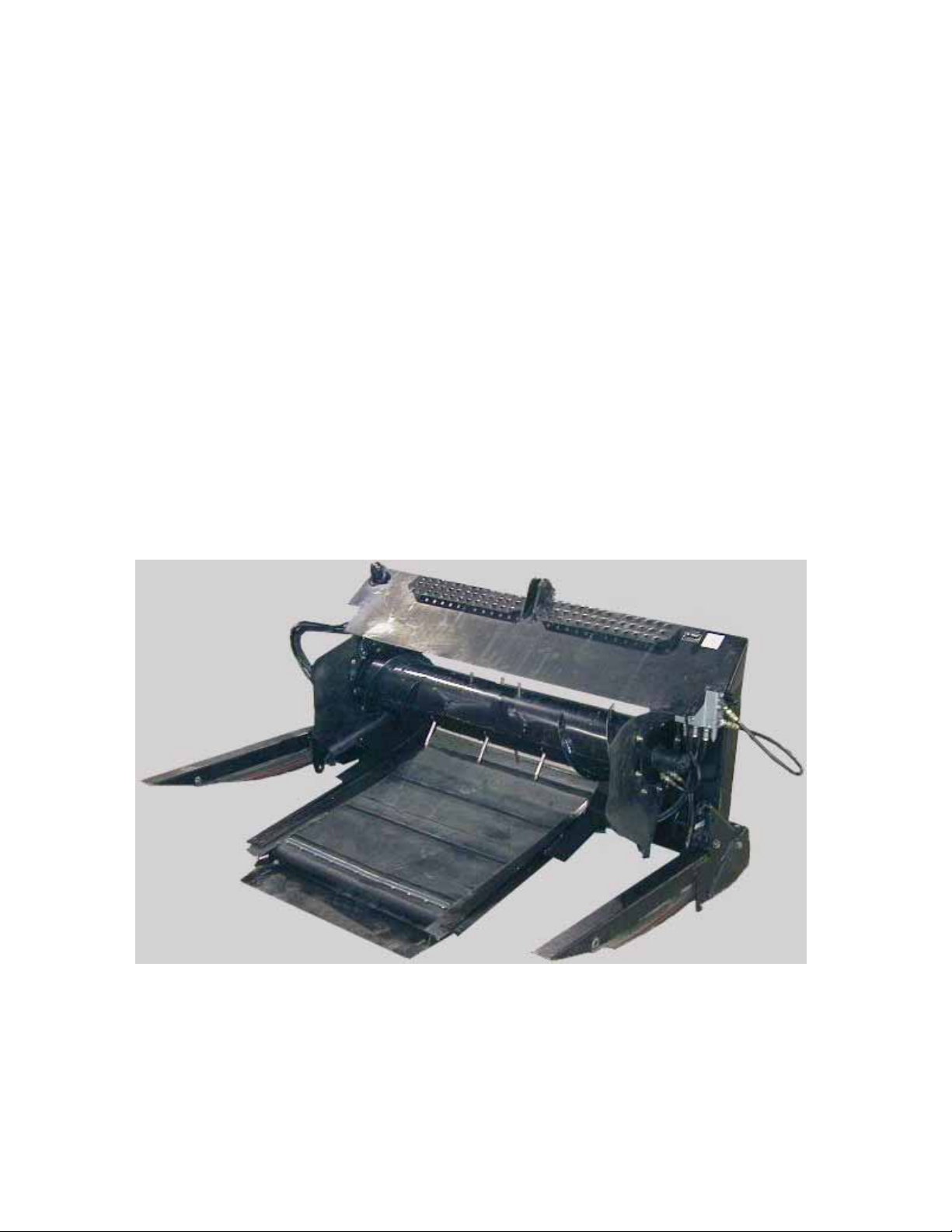
This Manual contains information on the adapter which is required to allow attachment of the MacDon Model
962 and 972 Harvest Header to the various models of combines (see list on cover).
NOTE: This supplement does not provide all the information required to operate the header. It must be used
in conjunction with your Harvest Header and Combine Operator’s Manuals.
CAREFULLY READ ALL MANUALS TO BECOME FAMILIAR WITH RECOMMENDED PROCEDURES
BEFORE ATTEMPTING TO UNLOAD, ASSEMBLE OR USE THE MACHINE.
This manual is divided into sections on: Safety, Attaching and Detaching the Header, Operation and
Maintenance/Service. In addition, Assembly and Adapter Mounting Instructions for each type of combine are
found at the back of this book.
Use the Table of Contents and the Index to guide you to specific areas. Study the Table of Contents to
familiarize yourself with how the material is organized.
Keep this manual handy for frequent reference and to pass on to new operators or owners. Call your dealer
if you need assistance, information or additional copies of the manual.
NOTE: Right hand (R/H), and Left hand (L/H) designations are determined from the operators position, facing
forward.
1
Page 2

TABLE OF CONTENTS
INTRODUCTION ........................................................................................................................................1
SPECIFICATIONS......................................................................................................................................3
SERIAL NUMBER LOCATION ...................................................................................................................3
SAFETY
Safety Alert Symbol................................................................................................................................4
Signal Words .........................................................................................................................................4
Safety Signs...........................................................................................................................................5
HEADER ATTACHING & DETACHING
Attaching Header to Combine and Adapter........................................................................................6-9
Detaching Header from Combine and Adapter...............................................................................10,11
Detaching Header and Adapter from Combine....................................................................................12
Attaching Header and Adapter to Combine.........................................................................................13
OPERATION
Break-In Period....................................................................................................................................14
Draper Speed Control..........................................................................................................................14
Header Flotation ..................................................................................................................................15
Header Levelling..................................................................................................................................16
Header Angle.......................................................................................................................................16
Widening the Delivery Opening ...........................................................................................................17
Windrowing with the Combine (972 Feed Pan Clearance Adjustment)...............................................17
MAINTENANCE/SERVICE
Service Procedures..............................................................................................................................18
Recommended Lubricants...................................................................................................................18
Enclosed Drive Lubricant Capacities ...................................................................................................18
Sealed Bearing Installation ..................................................................................................................19
Greasing the Adapter......................................................................................................................19,20
Hydraulic System
Hydraulic System Safety...................................................................................................................21
Hoses and Lines ...............................................................................................................................21
Hydraulic Schematic .........................................................................................................................21
Hydraulic Oil......................................................................................................................................22
Hydraulic Oil Filter.............................................................................................................................22
Flow Control Relief Pressure ............................................................................................................23
Gearbox Lubrication.............................................................................................................................23
Retracting Tine Drum...........................................................................................................................24
Maintenance Schedule ........................................................................................................................25
Maintenance Record............................................................................................................................26
TROUBLESHOOTING........................................................................................................................27, 28
ATTACHMENTS.......................................................................................................................................29
ASSEMBLY
962 Header Completion Parts .............................................................................................................30
Header Side Drapers & Feeder Deck..................................................................................................31
Feed Draper.........................................................................................................................................32
Center Link...........................................................................................................................................33
Position Retracting Tine Drum.............................................................................................................34
Electrical ..............................................................................................................................................35
Adjustments and Checks.....................................................................................................................36
ADAPTER MOUNTING INSTRUCTIONS
John Deere .....................................................................................................................................37-41
Case IH...........................................................................................................................................42-47
Gleaner...........................................................................................................................................48-54
New Holland....................................................................................................................................55-61
Cat Lexion.......................................................................................................................................62-67
Attaching Adapter to Header (without combine)..................................................................................68
Float Spring Removal or Installation..............................................................................................69, 70
Float Limiter Installation: John Deere 50 Series, Contour Master & New Holland TR Combines .......71
INDEX.......................................................................................................................................................72
2
Page 3

SPECIFICATIONS
FEED DRAPER DRIVE Hydraulic: Pump driven from right side of feeder house, reversible
with combine feeder chain
FEED DRAPER SPEED 522 to 652 feet/min. (159 to 199 metres/min.) varies with combine
FEED DRAPER MATERIAL Self-tracking rubber coated polyester fabric with rubber slats
FEED DRAPER WIDTH:
John Deere & New Holland TX, Cat Lexion 460, 465, 480 & 485 ......................55.9 inches (1420 mm)
Case 80 & 88 Series, Cat Lexion 450, 470 & 475 ..............................................45.5 inches (1155 mm)
Case 60 & 66 Series, Gleaner, & New Holland TR...............................................38.4 inches (975 mm)
RETRACTING TINE DRUM DRIVE Hydraulic: Pump driven from right side of feeder house, reversible
with combine feeder chain
RETRACTING TINE DRUM SPEED 173 to 216 RPM, varies with combine
RETRACTING TINE DRUM DIA.
John Deere & New Holland TX, Cat Lexion 460, 465, 480 & 485 ...........................12 inches (300 mm)
Case, Gleaner, New Holland TR & Cat Lexion 450, 470 & 475..................................11” (280 mm) with
1 ¼” (32 mm) flighting on ends
HEADER SIDE DRAPER DRIVE Hydraulic: Pump driven from right side of feeder house
HEADER SICKLE DRIVE Mechanical: Driveline from left side of feeder house
HEADER FLOTATION 7 inches (175 mm) vertical and 4.5° lateral
HEADER REEL DRIVE Hydraulic from combine oil supply
SERIAL NUMBER LOCATION
Record the serial number in the space provided.
872 Combine Adapter:
Plate (A) is located on left side of adapter
frame.
A
COMBINE ADAPTER SERIAL PLATE
NOTE: When ordering parts and service, be sure to give your dealer the complete and proper serial number.
3
Page 4

SAFETY
SAFETY ALERT SYMBOL
This safety alert symbol indicates important safety messages in this manual and
on safety signs on the header.
This symbol means:
ATTENTION !
BECOME ALERT !
YOUR SAFETY IS INVOLVED !
Carefully read and follow the safety message accompanying this symbol.
Why is SAFETY important to you?
· ACCIDENTS DISABLE AND KILL
3 BIG REASONS · ACCIDENTS COST
· ACCIDENTS CAN BE AVOIDED
SIGNAL WORDS
Note the use of the signal words DANGER, WARNING, and CAUTION with safety messages. The appropriate
signal word for each message has been selected using the following guidelines:
DANGER – Indicates an imminently hazardous situation that, if not avoided, will result in death or
serious injury.
WARNING – Indicates a potentially hazardous situation that, if not avoided, could result in death
or serious injury. It is also used to alert against unsafe practices.
CAUTION – Indicates a potentially hazardous situation that, if not avoided, may result in minor or
moderate injury. It is also used as a reminder of good safety practices.
4
Page 5
SAFETY
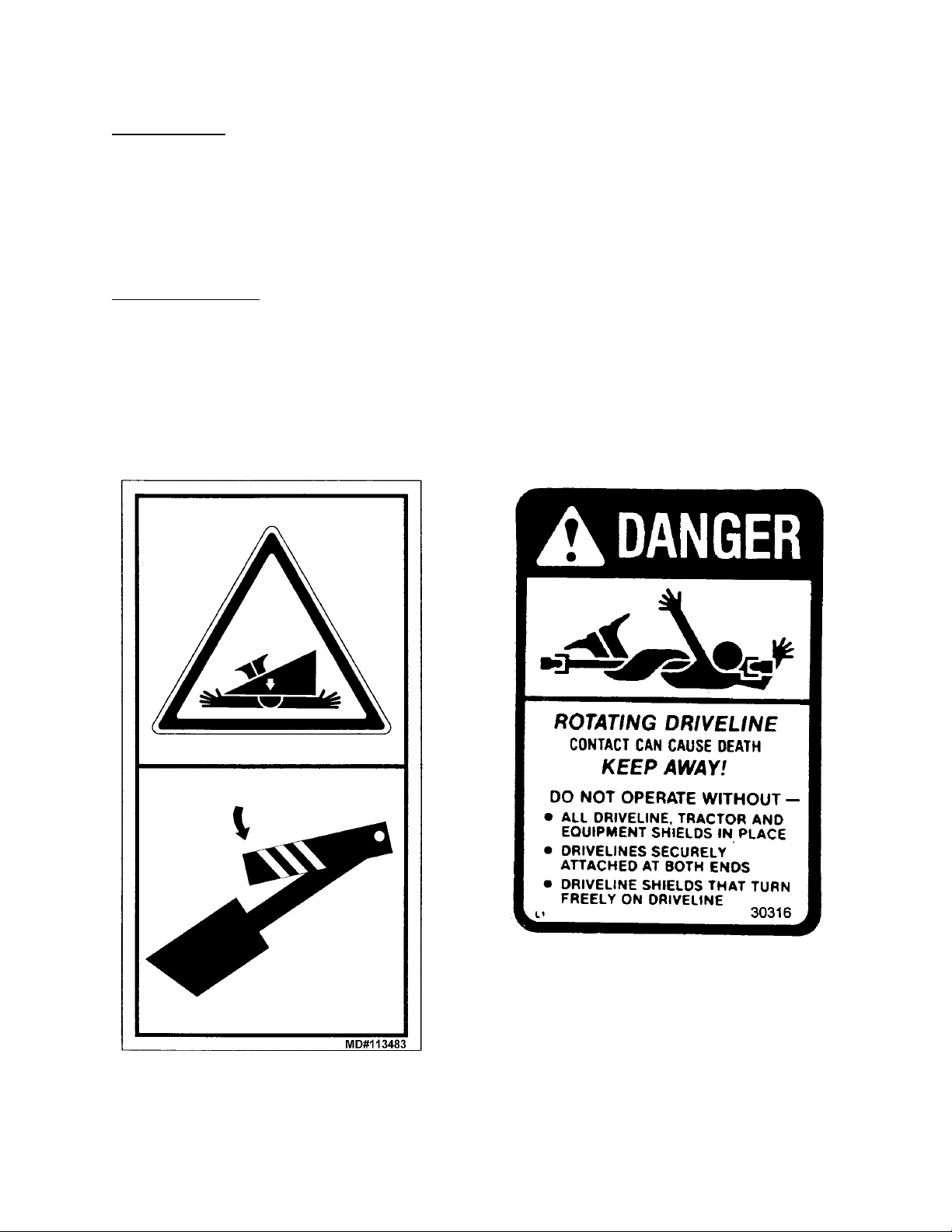
SAFETY SIGNS
• The safety signs below appear on the combine adapter.
• Keep safety signs clean and legible at all times
• Replace safety signs that are missing or become illegible.
• If original parts on which a safety sign was installed are replaced, be sur e the repair part als o bear s the
current safety sign.
• Safety signs are available from your Dealer Parts Department.
To install safety signs:
1. Be sure the installation area is clean and dry.
2. Decide on the exact location before you remove the decal backing paper.
3. Remove the smaller portion of the split backing paper.
4. Place the sign in position and slowly peel back the remaining paper, smoothing the sign as it is applied.
5. Small air pockets can be smoothed out or pricked with a pin.
Rest header on ground or engage mechanical
locks before going under unit.
5
Page 6
HEADER ATTACHING & DETACHING
ATTACHING HEADER TO COMBINE AND ADAPTER
1. Attach adapter to combine feeder housing. See
"Adapter Mounting Instruction" at back of book.
NOTE: If header has been previously attached
to windrower, remove linkage supports from
header lower legs. Connector shaft on header
back tube may remain installed.
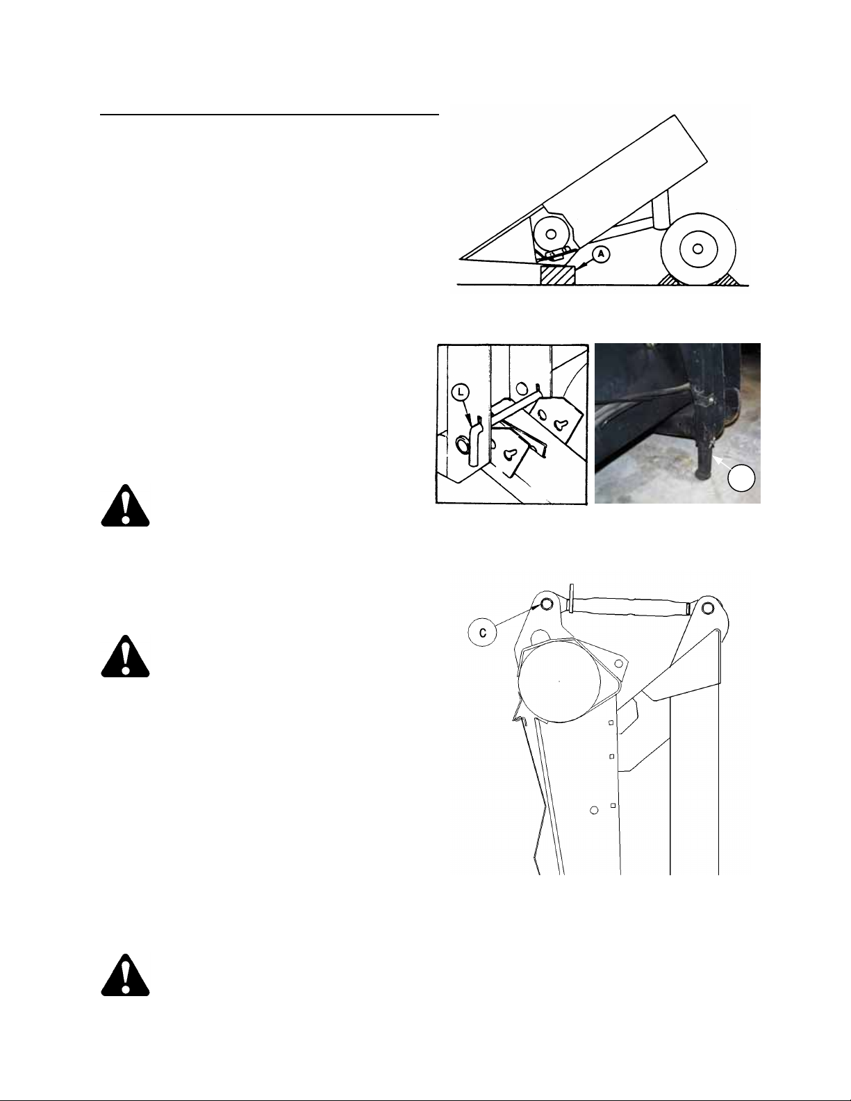
2. Choose an area that is as level as poss ible,
and place supports (A) at both ends of
cutterbar. For 962 Headers use 6" (150 mm )
blocks. For 972 Headers use 2x4 (40 mm)
blocks.
3. For 962 headers with gauge w heel s, block both
wheels front and rear, and be sure gauge
wheel pins are in stand position (L), both sides,
to support rear of header.
For 972 headers and 962 headers without
gauge wheels, be sure header stand (B) is
secure in the down position. For 962 Headers
only, place a 4 inch (100 mm) block under
stand.
CAUTION: Be sure area is clear of
bystanders before starting engine.
BLOCK CUTTERBAR
B
GAUGE WHEELS - 962 HEADER STAND - 972
4. Slowly drive combine forward, aligning float leaf
springs under header legs, unti l t op link can be
connected. Connect top link (C).
NOTE: For headers with hydraulic top link, see
instruction in “Unloading & Assembly” section.
CAUTION: Always connect top link
before raising header.
IMPORTANT: Take care not to crush hydraulic
hoses when driving into header.
IMPORTANT: For 972 Headers, when driving
into header, align notches in adapter feed pan
with retainers welded to cutterbar. Ensure that
pan goes under the retainer and on top of
cutterbar. The feeder house can be rais ed to
lower the front edge of the pan, and vice versa.
In soft ground conditions, a length of 2x4 under
the pan will prevent scooping dirt
5. Raise adapter slowly, making sure float leaf
springs engage in header legs. Continue to lift
until header is fully raised. Stop engine and
remove key.
CONNECT TOP LINK BEFORE LIFTING
DANGER: To avoid bodily injury
from fall of raised header, engage
header lift cylinder stops when
working on or around rais ed hea de r . Se e your
Combine Operator’s Manual for details.
6
Page 7
HEADER ATTACHING & DETACHING
ATTACHING HEADER TO COMBINE AND ADAPTER
(continued)
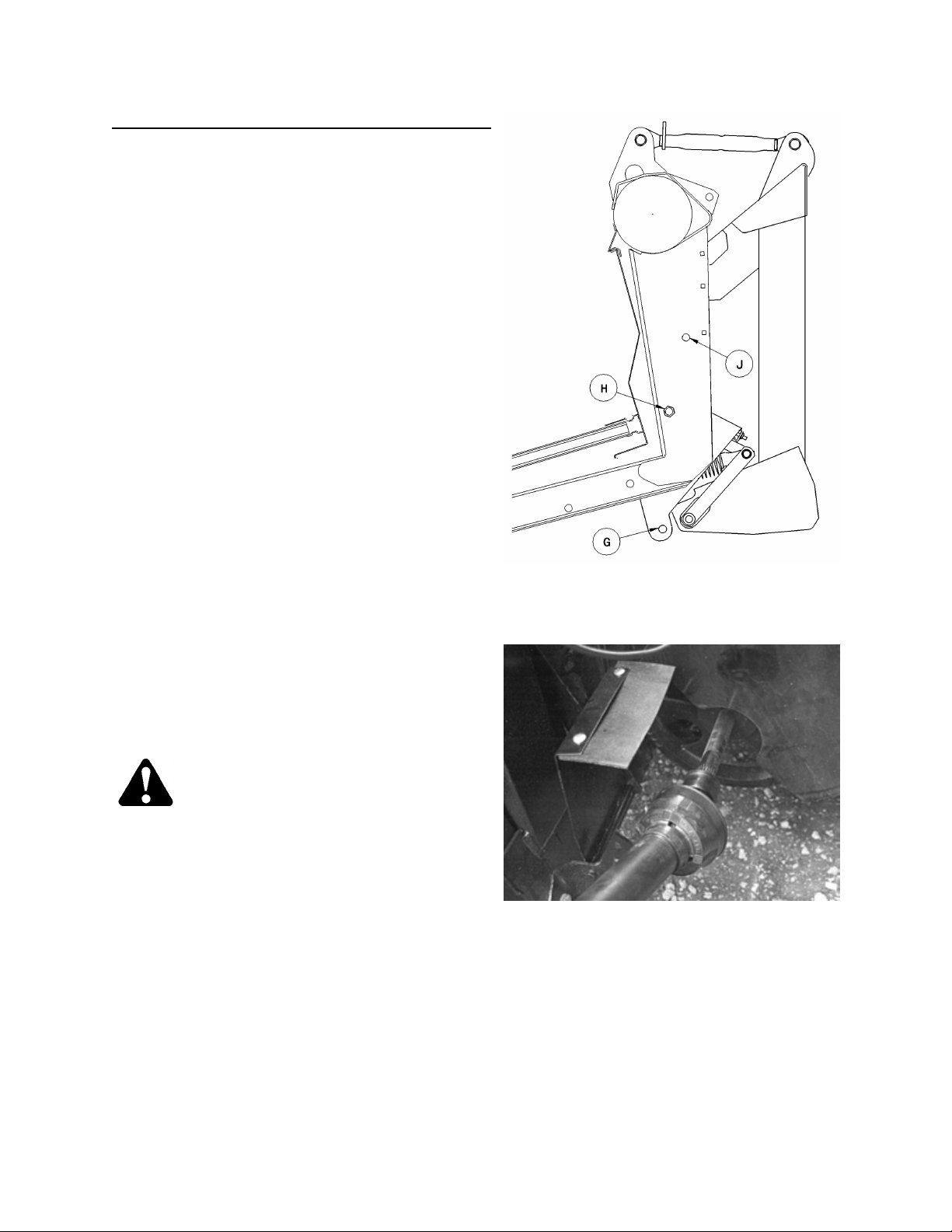
6. Remove ¾ x 7 ½” bolt and lock nut from
storage position (J) (or, on first use, from
shipping position [G]) and install to lock adapter
to header at (H). Move clevis pin from float
lockout position (G) to storage position (J).
Install split ring to capture clevis pin.
NOTE: It may be necessary to rock header by
lifting at divider to properly position float frame
at header leg joint.
Repeat at other leg.
7. Install sickle driveline on combine feeder house
shaft. Ensure driveline locking mechanism
engages. See your combine Operator's
Manual.
DANGER: Entanglement with
rotating driveline will cause
serious personal injury or death.
Keep all driveline shields in place.
Close all hinged covers.
BOLT ADAPTER TO HEADER & MOVE
PIN FROM FLOAT LOCKOUT TO STORAGE
ATTACH DRIVELINE
7
Page 8
HEADER ATTACHING & DETACHING
ATTACHING HEADER TO COMBINE AND ADAPTER
(continued)
8. Make the hydraulic line connections:
Reel drive pressure and return lines: Connect
two hoses between header and combine.
Reel lift line: Connect one hose between
header and combine.
Draper drive pressure and return lines:
Connect two hoses between header and
adapter.
NOTE: As an aid in connecting hydraulics, the
following colour coding has been used:
ORANGE - Draper Drive Pressure
BLUE - Draper Drive Return
YELLOW - Reel Drive Return
Reel fore-aft lines (if equipped): Connect two
hoses between header and combine.
9. Connect wiring harness between header and
combine. NOTE: A harness adapter is supplied
with adapter completion package.
10. For 962 headers with gauge wheels, rem ove
pins at gauge wheels and place in field position
(F). See “Cutting Height” in Header Operator’s
Manual to choose between alternate field
positions. (For headers with gauge
wheel/transport option, gauge wheel support is
not exactly as illustrated. See decal at support.)
NOTE: Rotate pin to align roll pin with key slot
for removal and installation. Roll pin locks
inside to secure the position.
11. For 972 headers and 962 headers without
gauge wheels, raise header stand to storage
position (G).
12. For 972 Headers, for initial setting, set header
at flattest angle (shortest top link length) and
float header up. Ensure that feed pan is as far
forward as possible and tighten pan hardware.
STEPS 13 to 16 A R E FOR 9 62 H EADERS ONLY.
13. Place 6" (150 mm) block under front of adapter
feeder pan. Ensure all feed pan-to-cutterbar
anchors are removed or turned sideways to
prevent damage to anchors when cutterbar is
lowered. Adju st feed pa n ful l y forward for init ia l
setting. (See next page.)
14. Disengage header lift cylinder stops and slowly
lower header until adapter feed pan rests on
block, and cutterbar rests on feed pan.
962 GAUGE WHEELS - FIELD POSITION
G
HEADER STAND - STORAGE POSITION
8
Page 9
HEADER ATTACHING & DETACHING
SIDE VIEW
0 to 5mm
ATTACHING HEADER TO COMBINE AND ADAPTER
(continued)
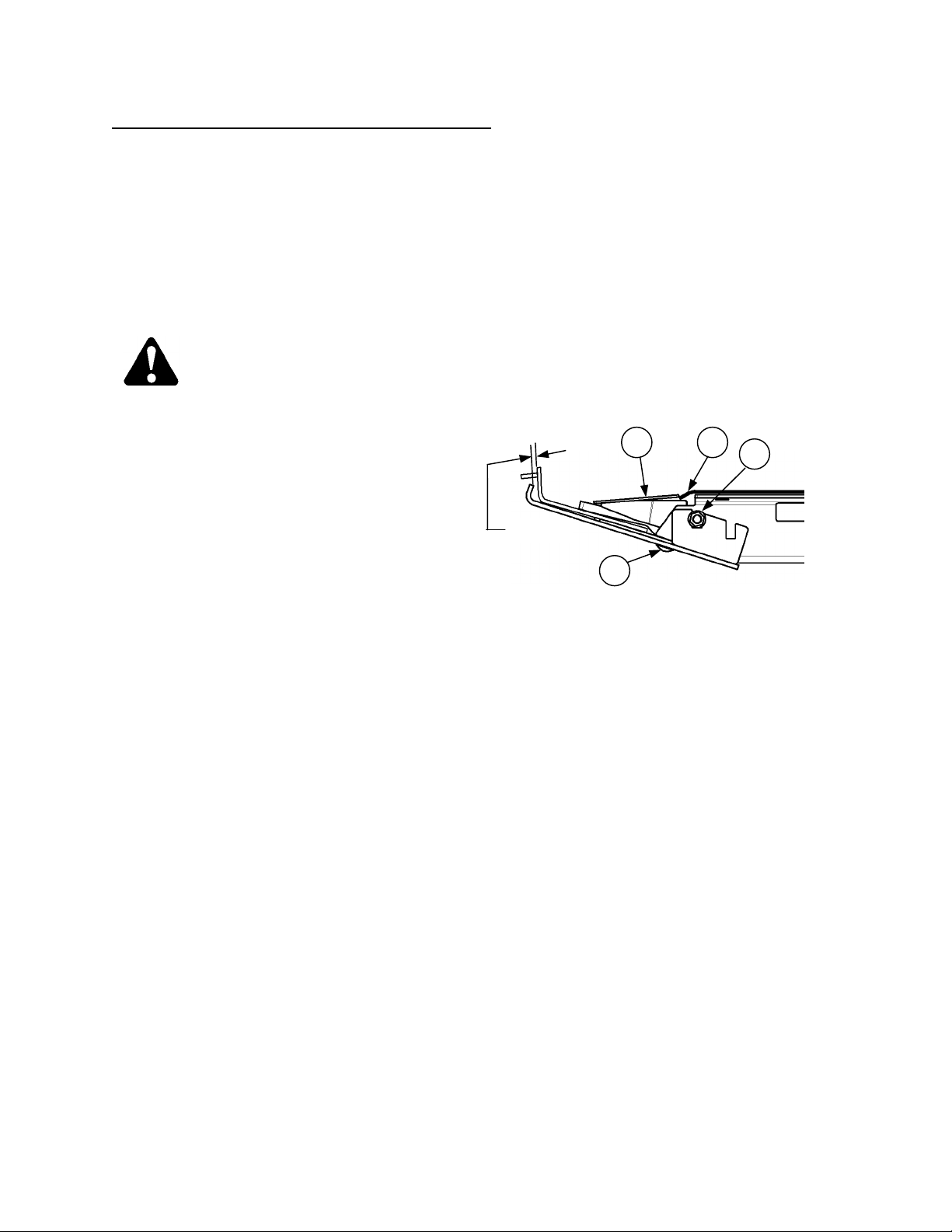
15. Install anchors to clamp feed pan to cutterbar
as shown.
16. Check for 0 to 5 mm (3/16 inch) clearance
between front of adapter feed pan and
cutterbar. Adjust clearance as follows:
a. Raise the header. Stop engine and remove
key.
DANGER: To avoid bodily injury
from fall of raised header, engage
header lift cylinder stops when
working on or around raised
header. See your Combine Operator’s Manual
for details.
b.
• Loosen bolts (F) and (G).
• Adjust feed pan clearance to cutterbar to 0 to
5 mm (3/16 inch).
• Tighten bolts (F) and (G).
• Remove all blocks, disengage header lift
cylinder stops and lower header to ground.
• Ensure that outside anchors (E) are ins talled
as shown, with rubber seal (J) under top plate
of anchor.
E J
F
G
ADJUST FEED PAN - 962 HEADER
9
Page 10
HEADER ATTACHING & DETACHING
DETACHING HEADER FROM COMBINE AND ADAPTER
Using this procedure, adapter will remain attached
to the combine. This would be appropriate when
header is to be used as a windrower. Instructions
for detaching both header and adapter from
combine are given on page 12.
1. Choose a level area. Lower the reel and raise
the header. Stop engine and remove key.
DANGER: To avoid bodily injury from
fall of raised header, engage head er
lift cylinder stops when working on
or around raised header. See your Combine
Operator’s Manual for details .
DANGER: Wait for all movement to
stop. A rotating driveline can cause
entanglement resulting in serious
personal injury or death.
2. Disconnect driveline from f eeder house shaft
and store at bracket (A) on header left leg.
3. Disconnect hydraulic lines:
- Reel lift between header and combine.
- Reel drive pressure and reel return between
header and combine.
- Draper return (blue) and draper drive pressure
(orange) between adapter and header.
- Reel fore-aft hoses between header and
combine (if equipped).
IMPORTANT: Couple or cap all lines to prevent
hydraulic system contamination except as noted
in Warning below. Be sure header stor ed hoses
and combine stored hoses are not entangled.
A
STORE DRIVELINE
WARNING: For headers with
hydraulic reel fore-aft, never connect
the fore-aft couplers to each other.
This would complete the circuit and allow the
reel to creep forward in transport, resulting in
instability.
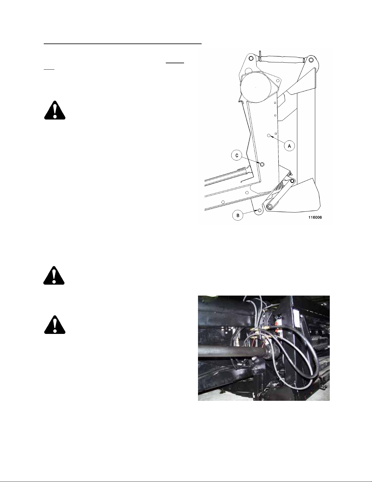
4. Disconnect wiri ng ha rn ess bet w e en he ad er a nd
combine.
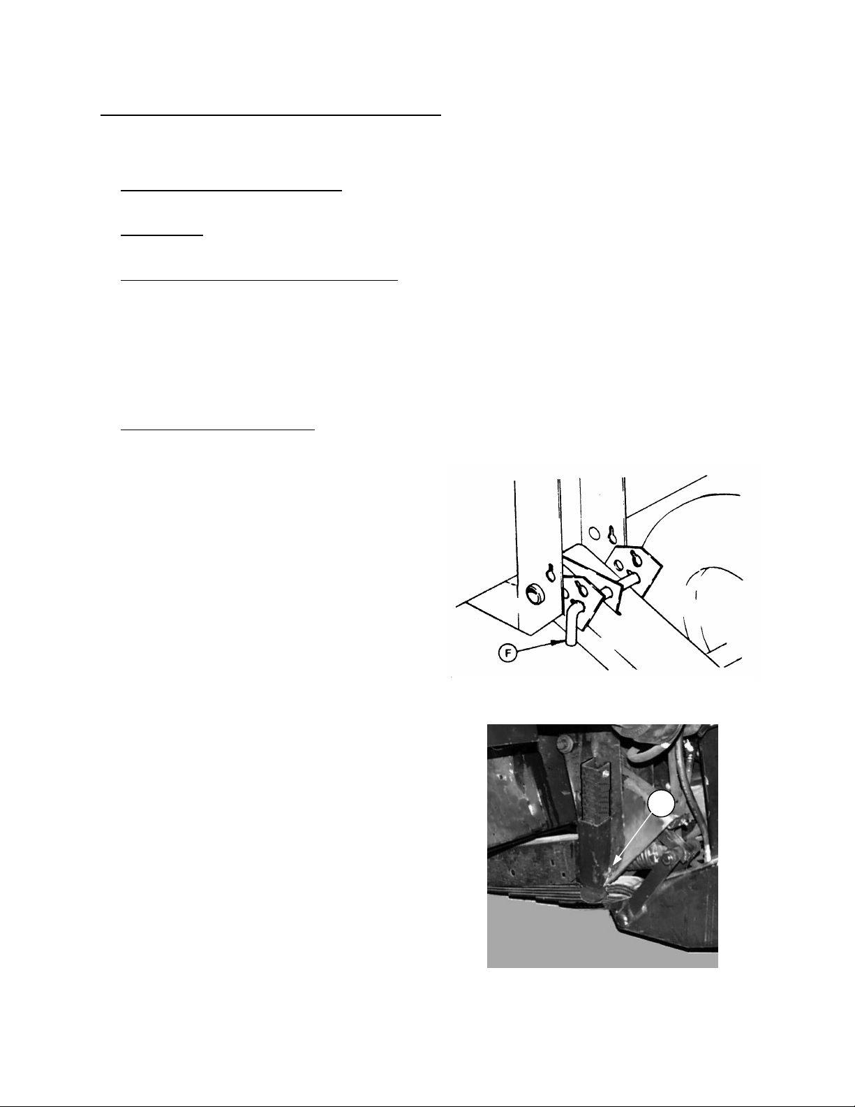
5. Remove split ring and clevis pin f rom storage
position (E) and install in float lockout position
(C). Remove ¾ X 7 ½” bolt and lock nut from
adapter lock position (B) and place in s torage
position (E). Repeat at other leg.
6. Remove plastic wear strip from under adapter
pan, if equipped. Leave wear strip attached to
clips on cutterbar.
STEPS 7 TO 12 ARE FOR 962 HEADERS ONLY.
FOR 972 HEADERS, GO TO STEP 13.
7. Set 6" (150 mm) blocks under the adapter
feeder pan.
8. Disengage header lift cylinder stops and lower
header so feeder pan rests on blocks.
9. Loosen and rotate cutterbar anchors (D) away
from cutterbar.
INSTALL PIN IN FLOAT LOCKOUT &
ENGAGE FLOAT LOCK-OUT AND
MOVE BOLT TO STORAGE POSITION
D
RELEASE CUTTERBAR ANCHORS –
962 HEADERS
10
Page 11
HEADER ATTACHING & DETACHING
DETACHING HEADER FROM COMBINE AND ADAPTER
(continued)
10. Raise header and engage header lift cylinder
stops.
11. Move 6" (150 mm) bloc ks from under adapter
feeder pan to the outside, about 18" (450 mm)
from each end of header.
12. For 962 headers with gauge wheels, rem ove
pins at gauge wheels and place in stand
position (B). Block both gauge wheels.
For 962 headers without gauge wheels, lower
header stand and place a 4 inch (100 mm)
block beneath stand.
13. For 972 Headers, lower header stand (E).
Place a 2x4 under stand only if required for
stability on soft ground. Place 2x4’s (40 mm
blocks) under cutterbar , about 18" (450 mm)
from each end of header.
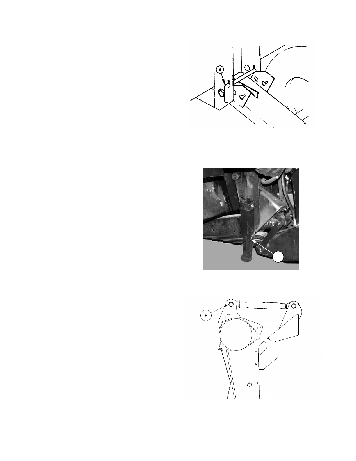
14. Disengage header lift cylinder stop s and lower
header onto blocks. Lower a dapter unti l top l ink
is loose. Detach top link (F).
962 GAUGE WHEELS - STAND POSITION
E
HEADER STAND - LOWERED
15. Lower adapter until float leaf springs are clear
of header legs and slowly back away from
header.
DISCONNECT TOP LINK
11
Page 12
HEADER ATTACHING & DETACHING
DETACHING HEADER AND ADAPTER FROM COMBINE
Using this procedure, adapter will remain attached to
the header. This would be ap pro priat e when detaching
header for transport. Instructions for detaching header
only from adapter and combine are given on page 10.
1. Choose a level area. Lower the reel and raise the
header. Stop engine and remove key.
DANGER: To avoid bodily injury from
fall of raised header, engage header lift
cylinder stops when working on or
around raised header. See your
Combine Operator’s Manual for details.
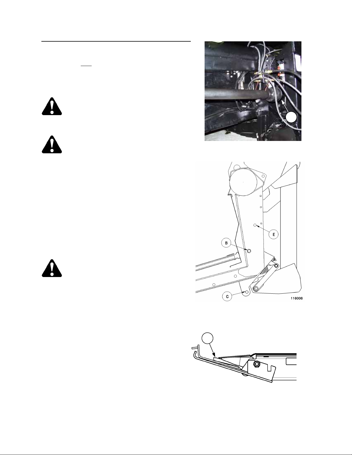
2. Remove split ring and clevis pin from storage
position (A) and install in float lockout positio n (B).
Repeat at other leg. Note that bolt in adapter lock
position (C) remains in place.
3. Disconnect hydraulic lines between header and
combine:
- Reel drive pressure line.
- Reel drive return line.
- Reel lift line.
- Reel fore-aft lines (if equipped).
NOTE: For units with hydraulic center link, before
disconnecting cylinder hoses, turn off oil flow at shutoff valve. This allows easier reattachment of couplers
at combine. Remem ber to r estore oil f low at shut-of f
valve before next use.
INSTALL PIN IN LOCKOUT POSITION
IMPORTANT: Couple or cap all lines to prevent hydraulic system contamination except as noted in Warning
below. Be sure header stored hoses and combine stored hoses are not entangled.
WARNING: For headers with hydraulic reel fore-aft, never connect the fore-aft couplers to
each other. This would complete the circuit and allow the r eel to c ree p forward in tr ansport,
resulting in instability.
4. Disconnect wiring harness between header and
combine.
DANGER: Wait for all mo vement to stop
before appr o ac hi ng dr iv el in e . A rota ti ng
driveline can cause entanglement
resulting in serious personal injury or
death.
5. Disconnect dr iveline from combine feeder house
output shaft and store at header left leg.
6. Disconnect pump from combine feeder house
output shaft and store on adapter. See Mounting
Instruction for your mak e of combine at back of
book.
NOTE: Wear gloves when handling pump.
7. Disengage the header lock system. See Mounting
Instruction for your make of combine at back of book.
DISCONNECT AND STORE DRIVELINE
8. Disengage header lift cylinder stops, start engine and lower header to ground.
9. Slowly back combine away from header.
12
Page 13
HEADER ATTACHING & DETACHING
ATTACHING HEADER AND ADAPTER TO COMBINE
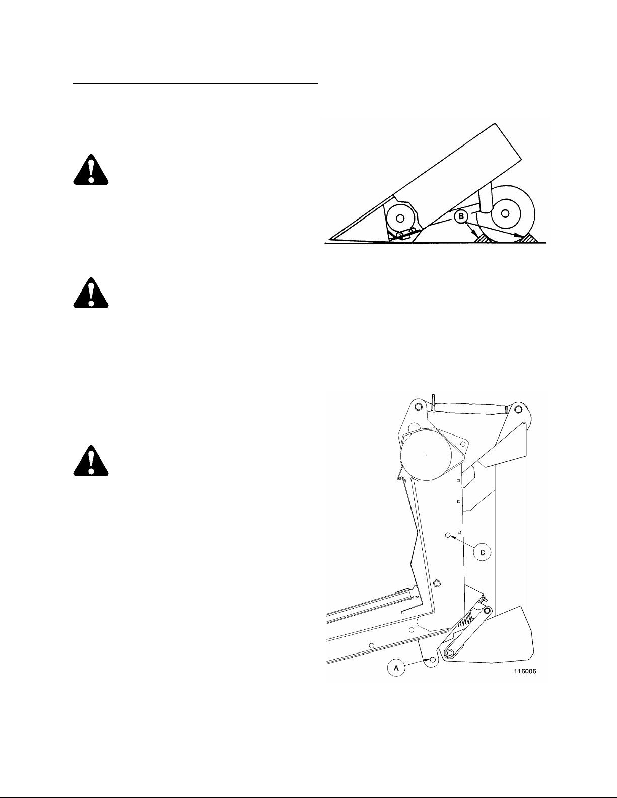
1. If applicable, block both gauge wheels front
and rear (B).
NOTE: Choose an area that is as level as
possible.
CAUTION: Be sure area is clear of
bystanders before starting engine.
2. Drive combine slowly forward and engage
feeder house lifting device in adapter top cross
member. See Mounting Instruction for your
make of combine at back of book for details.
3. Raise header, stop engine and remove key.
DANGE R: To avoid bodil y injur y fr om
fall of raised header, engage header
lift cylinder stops when working on
or around raised header. See your Combine
Operator’s Manual for details .
4. Connect feeder house lock system at bottom of
adapter. See Mounting Instruction for your
make of combine at back of book.
5. Install sickle driveline on L/H feeder house
output shaft. Ensure driveline locking
mechanism engages. See your combine
Operator’s Manual.
DANGER: Entanglement with
rotating driveline will cause serious
personal injury or death. Keep all
driveline shields in place.
6. Connect hydraulic lines between header and
combine:
- Reel drive pressure line.
- Reel drive return line.
- Reel lift line.
- Reel fore-aft lines (if equipped).
BLOCK GAUGE WHEELS
7. Connect wiring harness between header and
combine.
8. Remove split ring and clevis pin from float
lockout position (A) and install in storage hole
(C). Repeat at other leg.
9. Install pump on R/H feeder house output shaft.
See Mounting Instruction for your make of
combine at back of book.
NOTE: Wear gloves when handling pump.
10. Disengage header lift cylinder stop s and lower
header.
REMOVE PIN FROM FLOAT LOCKOUT
13
Page 14
BREAK-IN PERIOD
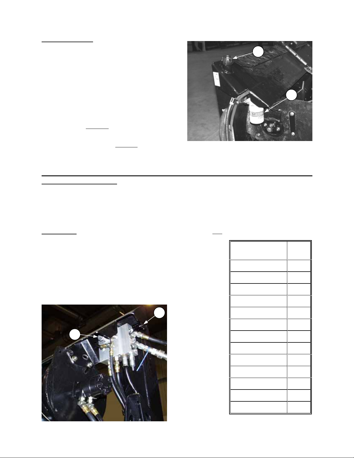
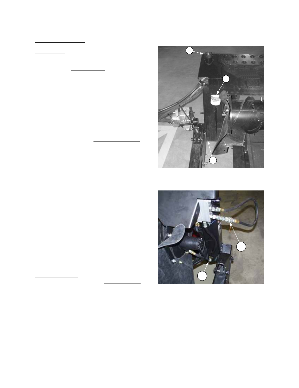
CHECK HYDRAULIC OIL LEVEL
OPERATION
1. Run drapers slowly for 5 minutes to fill hydraulic
A
lines, then check oil level at (A). Maintain level
between LOW and FULL when oil is cold.
NOTE: Breather screw on cap (A) has been
tightened for shipping. Loosen screw before
operating adapter.
NOTE: When ambient temperatures are above
35º C (95º F), maintain oil level in the low portion
D
of the range to prevent ov erflow at breather und er
operating temperatures.
2. Change the hydraulic oil filter (D) on combine
adapter after 50 hours operation and every 250
hours thereafter.
3. Change gearbox oil after 50 hours oper ation and
every 1000 hours or 3 years thereafter.
CHANGE OIL FILTER & GEARBOX OIL
See "Break-In Period" in Header Operator's Manual for further information on break-in maintenance.
DRAPER SPEED CONTROL
Speed of the header drapers is adjusted at the flow control on the combine adapter. Rotate flow control knob
(C) to a number suited to the crop. The higher the number, the faster the draper speed. The settings in the
chart are recommended for optimum feeding capacity.
NOTE: If sufficient draper speed cannot be achieved, a possible caus e is low relief pr essure. See "Flow
Control Relief Pressure" in Maintenance/Service section.
Needle Valve: When laying a windrow, turn needle valve control (B) fully
and drum.
NOTE: Valve must be fully open to prevent rotation of feed draper and
drum when oil is cold. It may also be necessary to secure drum to
prevent rotation.
For a complete list of steps to convert to windrowing mode, see “End
Delivery” in the Operation section of your Header Operator’s Manual.
When straight cutting and experiencing plugging at the rear of the
feeder deck, turn control (B) to slow feed draper and drum.
NOTE: Slowing feed draper and drum too much will cause feeding
problems. Turn needle valve control (B) in 1/16 turn increments.
C
B
open to stop flow to the feed draper
DIAL
CROP
NO.
Barley 3
Beans, Edible 4
Canola 3
Flax 5
Lentils 3
Milo 3
Oats 3
Peas 3
Rice 5
Safflowers 4
Soybeans 5
Sunflowers 4
DRAPER SPEED CONTROL
Wheat 3
14
Page 15
OPERATION
HEADER FLOTATION
IMPORTANT:
To avoid:
- frequent breakage of sickle components
- scooping soil
- soil build-up at cutterbar in wet conditions,
set header float as light as possible without
causing excessive bouncing.
To check header float:
1. Raise feeder house and engage lift cylinder
stops.
2. Be sure float lock out pins are removed f rom
position (C).
3. Disengage lift cylinder stops and lower header
so the cutterbar is 1 to 6 inches (25 to 150 mm)
above the ground.
NOTE: When cutterbar is in the range from 0 to 16
inches (400 mm) off ground, float arm should
touch or be within ¼ inch (6 mm) of angle at (A). If
gap at (A) is greater than ¼ inch, float is set too
light, causing the header to float up.
NOTE: Header gets lighter and gap at (A)
increases when steepening header angle. Adjust
float after changing header angle or reel f ore-aft
position. For best float, gap at (A) should never
exceed ¼ inch (6 mm).
4. W ith cutterbar 1 to 6 inches (25 to 150 m m)
above the ground, grasp the crop divider rod
and lift up. Under normal conditions it should
require 50 to 70 lbs. force (220 to 310 N) to lift
cutterbar off ground at either end. If adjustment
is required, proceed as follows:
To adjust header float:
1. Raise feeder house and engage lift cylinder
stops.
2. Tighten bolts (B) at both sides of adapter to
increase float (which makes header lighter
when lowered to ground).
Loosen bolts to decrease float (which mak es
header heavier when lowered).
IMPORTANT: For 21 ft. 972 headers only. If
header still has excess float with float
adjustment bolt fully backed off, it may be
necessary to remove the 3
the top on both sides of the adapter to provide
proper floatation. See Unloading and Assembly
section for removal instructions.
rd
leaf spring from
FLOAT ADJUSTMENT
15
Page 16
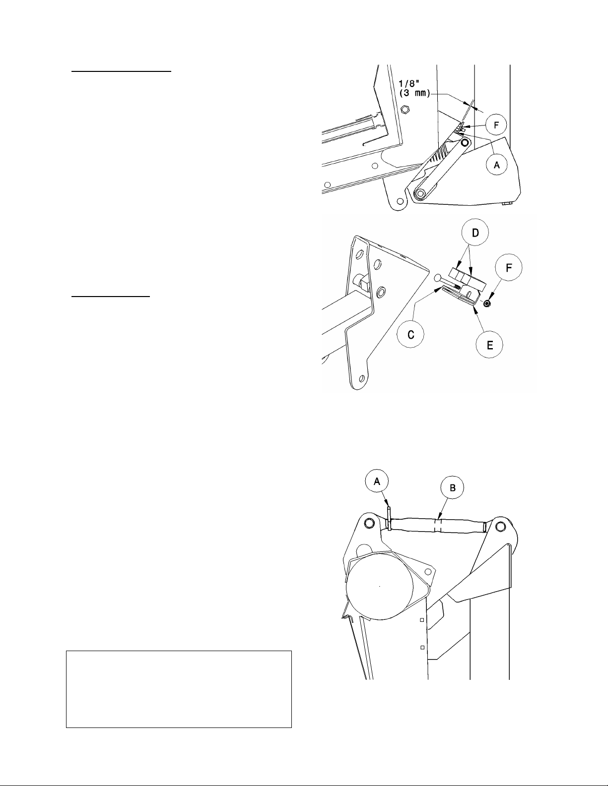
OPERATION
HEADER LEVELLING
Adjust header levelling with header at the flattest angle.
See Header Angle, below.
1. With header on level ground, lower header so
cutterbar is 2 to 4 inches (50 to 100 mm) off the
ground.
2. Check level of header by measuring cutterbar to
ground at both ends.
3. To lower cutterbar on one end, remove a shim (C)
from between rubber pads (D) and angle (E).
Adjust shim quantity side to side, placing from 0 to
2 shims to level header. To add or remove a shim:
• Lower cutterbar to ground and continue lowering
feeder house so gap at (A) increases.
• Remove nut (F) and add or remove shim(s) as
required.
• Reassemble, maintaining 1/8 inch (3 mm) between
angle and float support as shown.
HEADER ANGLE
The header (or guard) angle can be adjusted from
15° to 20° below horizontal. (Actual angle may vary with
combine set-up.)
See Combine Operator’s Manual for header levelling
and additional header angle adjustments.
IMPORTANT: The flat header angle (15°) is
recommended f or normal conditions. A flatter header
angle reduces sickle section breakage and reduces soil
scooping or build-up at the cutterbar in wet conditions.
Use a steeper angle to cut very close to the ground, or
in down crop for better lifting action.
IMPORTANT: Always check adapter drum clearance to header frame after adjusting header angle. Flattening
the header angle will reduce the clearance to the drum fingers.
IMPORTANT: Header flotation gets lighter as header
angle increases, and must be readjusted. See
"Header Flotation", on page 15.
To adjust header angle with mechanical link:
1. Lower cutterbar to ground and continue
lowering to drop feeder house another 2 to 5
inches (50 to 125 mm).
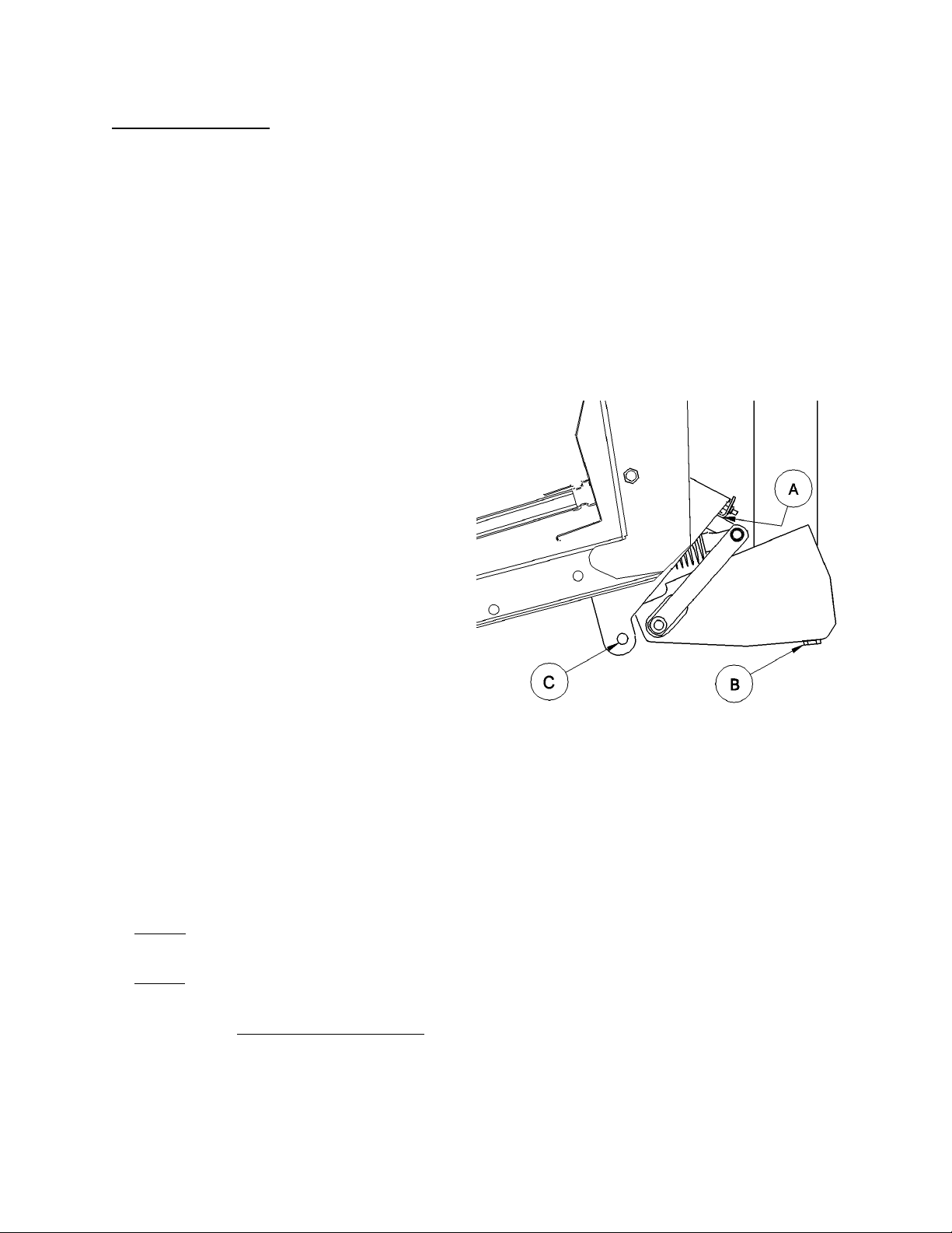
2. Back off the locking collar (A) on top link
turnbuckle.
3. Using a punch in hole in turnbuckle (B), turn to
adjust header angle.
Longer top link = steeper header angle
( = lighter float )
4. At desired adjustment, tighten locking collar (A)
securely against turnbuckle to fix the position.
HEADER LEVELLING
HEADER ANGLE HYDRAULIC ADJUSTMENT
An optional kit is available which allows adju stment
of header angle from the c om bine cab by means
of a hydraulic cylinder.
See “Unloading and Assembly” section for
information on assembly and use of this option.
HEADER ANGLE MECHANICAL ADJUSTMENT
16
Page 17
Assembled for Windrowing with a Combine
Assembled for Maximum Ground Clearance
OPERATION
WIDENING THE DELIVERY OPENING: Case, Gleaner & New Holland TR Combines:
In conditions where severe “bridging” is occurring (bulky crop being thrown across the opening), widen the
header side draper opening to allow the crop to fall onto the feed draper. See “Delivery Opening” in your
Header Operators’ Manual for procedure. To achieve smooth feeding after widening opening, add
outboard tines to the adapter drum. See “Tine Installation”, page 24.
Combine Model New Delivery Opening Qty. of tines to be added to drum
Case 60 & 66 Series, Gleaner, NH-TR 1060 mm (41.7”) 2 per side (4 total)
Case 80 & 88 Series 1260 mm (49.6”) 1 per side (2 total)
WINDROWING WITH THE COMBINE
To convert to windrowing mode (delivering crop to the end of the header) see “End Delivery” in the
Operation section of your Header Operator’s Manual.
972 Feed Pan: Ground Clearance Adjustment
H
G
F
Spacer plate (F) is factory assembled for best
ground clearance, with plate (F) mounted to the
forward set of holes in pan (G) as shown above
left. When windrowing with the combine and in
certain other conditions, clearances may be such
that the header drapers catch on the deck or on
angle (H). If so, move spacer plate (F) to rear set
of holes in pan (G) as shown above right. To
reposition spacer plate (F), proceed as follows:
• Remove two center bolts (K) and loosen bolts
at outside ends of pan.
• Slide spacer out (forward) and slide it in fr om
the back onto the loosened bolts.
• Replace the two center bolts, exchanging
positions so the 1 ¼ bolt again goes through
the spacer plate.
• Exchange positions of the bolts at outside ends
of pan so the 1 ¼ bolts go through spacer
plate.
F
G
K
17
Page 18

MAINTENANCE/SERVICE
SERVICE PROCEDURES
CAUTION: To avoid personal injury, before servicing machine or opening drive covers:
1. Fully lower header and reel. If it is necessary to service in the raised position, first
engage header lift cylinder stops and reel props.
2. Disengage header drive clutch.
3. Stop engine and remove key.
4. Engage park brake.
5. Wait for all moving parts to stop.
6. Park on level surface when possible. Block wheels securely. Follow all recommendations in your
Combine Operator’s Manual.
7. Wear close-fitting clothing and cover long hair. Never wear dangling items such as scarves or
bracelets.
8. W ear protective shoes with slip resistant soles, a hard hat, protective glasses or goggles and
heavy gloves.
9. Be prepared if an accident should occur. Know where the first aid kit and fire extinguisher are
located and how to use them.
10. Keep the service area clean and dry. Wet or oily floors are slippery. Wet spots can be dangerous
when working with electrical equipment. Be sure all electrical outlets and tools are properly
grounded.
11. Use adequate light for the job at hand.
12. Replace all shields removed or opened for service.
13. Use only service and repair parts made or approved by the equipment manufacturer. Substi tuted
parts may not meet strength, design or safety requirements.
14. Keep the machine clean. Never use gasoline, naphtha or any volatile material for cleaning
purposes. These materials may be toxic and/or flammable.
RECOMMENDED LUBRICANTS
GREASE
SAE Multi-Purpose High Temperature Grease with Extr eme Pressure (EP) Perf or mance and containing at
least 1.5% molybdenum disulphide.
Also acceptable is an SAE Multi-Purpose Lithium Base Grease.
HYDRAULIC OIL
Use single grade trans-hydraulic oil. If an oil brand from the recommended list is not available, use 15W40
engine oil.
The following oil company and equipment
manufacturer brand names are recommended:
Petro Canada Duratran
Case IH Hy-Tran Plus®
John Deere Quatrol® J20C
Agco Power Fluid 821XL
GEARBOX OIL
SAE 85W-140 gear lubricant (API Service Classification GL-5)
CAPACITIES
Adapter Gearbox - 450 mL (15 U.S. oz.)
Adapter Hydraulic System (Draper Drive)
Full system: 25 litres (6.6 U.S. gals.)
Tanks only: 17 litres (4.5 U.S. gals.)
STORING AND HANDLING LUBRICANTS
Your machine can operate at top efficiency only if clean lubricants are used. Contaminant in lubricants is the
most likely cause of bearing and hydraulic system failure. Use clean containers to handle all lubricants. Store
lubricants in an area protected from dust, m oisture and other contam inants. Keep hydraulic couplers and
connectors clean.
18
Page 19

MAINTENANCE/SERVICE
TIGHTEN COLLAR IN DIRECTION
SEALED BEARING INSTALLATION
1. Clean shaft and coat with rust preventative.
2. Install flangette, bearing, flangette and lock
collar. The locking c am is only on one side of
the bearing.
3. Install and tighten the flangette bolts.
4. When the shaft is located correctly, lock the
lock collar with a punch. The collar should be
locked in the same dir ection the s haf t r otates .
Tighten the set screw in the collar.
5. Loosen the flangette bolts on the mating
bearing one turn and re-tighten. this will allow
the bearing to line up.
SHAFT ROTATES
GREASING THE ADAPTER
See "Recommended Lubricants" in this section for
recommended greases.
The adapter has four greasing points as shown on
the following page. Use the hour meter in the
combine cab and the "Maintenance Checklist"
provided to keep a record of scheduled
maintenance.
Procedure:
1. Wipe grease f itting with a clean cloth before
greasing, to avoid injecting dirt and grit.
2. Inject grease through fitting with grease gun
until grease overflows fitting.
3. Leave excess grease on fitting to keep out dirt.
4. Replace any loose or broken fittings imm ediately.
5. If fitting will not take grease, remove and clean
thoroughly. Also clean lubricant passageway.
Replace fitting if necessary.
19
Page 20
MAINTENANCE/SERVICE
GREASING THE ADAPTER (continued)
100 Hours or Annually:
1. Drum Bearing (B) - one fitting
For access to grease zerk, turn drum until
drum access cover screws (E) are aligned with
the long fore-aft adjustment slot (F)
(approximately at the 1 o-clock position, viewed
from the center of the adapter).
F
ALIGN COVER SCREWS WITH SLOT
FOR ACCESS TO DRUM BEARING ZERK
B
E
DRUM BEARING
2. Feed Draper Idler Roller Bearings (C) two fittings
Replace bearings every 500 hours or annually.
3. Feeder Draper Drive Roller Bearing (D) one fitting
NOTE: To avoid damage to bearing seal, when
greasing drive roller bearing use a single slow
stroke of grease gun.
Replace bearing every 500 hours or annually.
C
FEEDER DRAPER IDLER ROLLER BEARINGS
D
FEEDER DRAPER DRIVE ROLLER BEARING
20
Page 21
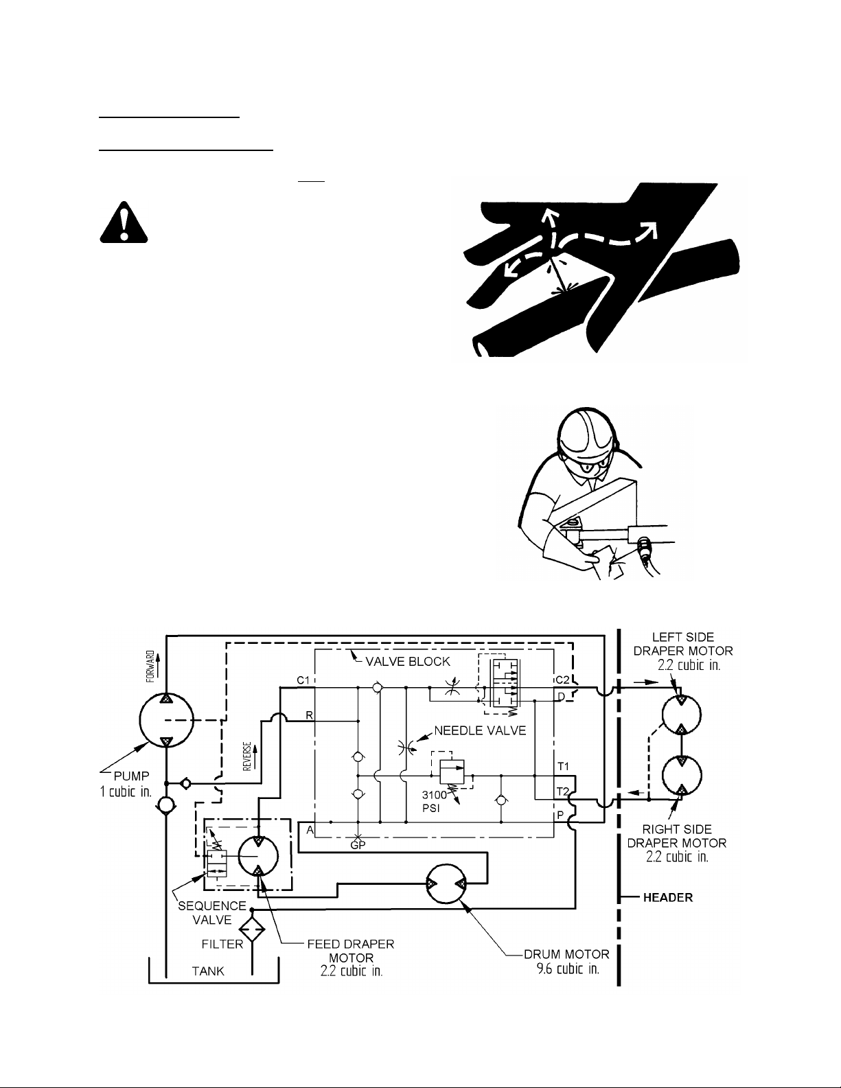
MAINTENANCE/SERVICE
HYDRAULIC SYSTEM
Hydraulic Hoses and Lines
Check hydraulic hoses and lines daily for signs of
leaks.
WARNING: Avoid high-pressure
fluids. Escaping fluid can penetrate
the skin causing serious injury.
Relieve pressure before disconnecting
hydraulic lines. Tighten all connections before
applying pressure. Keep hands and body away
from pinholes and nozzles that eject fluids
under high pressure. Use a piece of cardboard
or paper to search for leaks. IF ANY fluid is
injected into the skin, a doctor familiar with
this type of injury must surgically remove it
within a few hours or gangrene may result.
IMPORTANT:
• Ensure all hydraulic couplings are fully
engaged before operating header.
• Keep hydraulic coupler tips and connectors
clean. Dust, dirt, water and foreign material
are the major causes of hydraulic system
damage.
• To prevent improper mixing of oils:
If header is to be switched back and forth from
combine to windrower, change oil in windrower
tractor (or Bi-Directional Tractor) hydraulic
system to match combine hydraulic system.
AVOID HIGH PRESSURE FLUIDS
CHECK PROPERLY FOR LEAKS
COMBINE ADAPTER HYDRAULIC SCHEMATIC
21
Page 22
HYDRAULIC SYSTEM (continued)
MAINTENANCE/SERVICE
Hydraulic Oil
The combine adapter’s hydraulic system provides
oil for the draper and feed drum drives.
Check oil level every 25 hours at dipstick (A).
Maintain level betw een "LOW" and "FULL" marks
when oil is cold.
Capacity:
- Full system: 25 litres (6.6 U.S. gallons)
- Tanks only: 17 litres (4.5 U.S. gals.)
Type – See recommended lubricants, page 18.
NOTE: When ambient temperatures are above
35º C (95º F), maintain oil level in the low portion
of the range to prevent ov erflow at breather und er
operating temperatures.
Change hydraulic oil every 1000 hours or 3 years
To change hydraulic oil:
1. Remove dipstick cap (A).
2. Remove plug (B) at ri gh t res ervo ir a nd ho se (E )
at left reservoi r.
NOTE: A drain pan with a capacity of 15 litres
(4 U.S. gallons) will be required for each
reservoir.
3. Replace the hydraulic oil filter. See below.
4. Replace plug (B) and hose (E) and fill the
reservoirs through fem ale coupler (D) from a
pressurized oil source.
NOTE: Do not use cap por t (A) to fill s ystem.
Oil will not reach left reservoir. If a pressurized
source of oil is not available, pump oil from
right reservoi r to left as follows:
• Fill R/H reservoir with oil through cap port (A).
• Run the adapter pump until feed drum stops
turning.
• Re-fill R/H reservoir.
• Repeat procedure until oil level in R/H reservoir
remains between LOW and FULL on dipstick.
5. Replace cap (A).
A
C
B
RIGHT HYDRAULIC RESERVOIR
D
Hydraulic Oil Filter
Change hydraulic oil filter (C) after the first 50
hours operation and every 250 hours thereafter.
To change:
1. Clean around the filter head.
2. Remove the filter and clean the gasket surface
of the filter head.
3. Apply a thin film of clean oil to the gask et on
the new filter.
4. Install the new filter. Turn the filter onto the
mount until the gasket contacts the filter head.
Tighten the filter an additional 1/2 to 3/4 turn by
hand.
IMPORTANT: Do not use a filter wrench to install
the filter. Over-tightening can damage gasket and
filter.
E
LEFT HYDRAULIC RESERVOIR
22
Page 23

MAINTENANCE/SERVICE
HYDRAULIC SYSTEM (continued)
Flow Control Relief Pressure
A possible cause of insuff icient draper speed is
low relief pressure.
To check relief pressure:
1. Attach a 5000 psi (34.5 MPa) press ure gauge
in gauge port (GP) of valve block.
2. Install a needle valve between the orange
colour coded male coupler on adapter and the
orange colour coded female coupler on header.
NOTE: Using the needle valve built into the
valve block will not check relief pressure.
3. Set flow control knob to number 6 on dial.
4. Run combine engine at operating speed.
5. Engage header drive.
6. Close needle valve until flow stops. Pressure
reading should be 3100 psi (21.4 MPa).
WARNING: To avoid bodily injury
from bursting hoses and/or
exploding components, do not
exceed 3250 psi pressure (22.4 MPa). Do not
continue closing needle valve if pressure
exceeds 3250 psi (22.4 MPa).
GP
C
FLOW CONTROL RELIEF ADJUSTMENT
If relief pressure requires adjustment:
1. Loosen jam nut (C).
2. Turn relief screw until relief pressure is correct.
3. Tighten jam nut.
GEARBOX LUBRICATION
Change gearbox oil every 1000 hours or 3 years.
Box capacity: 450 mL (15 U.S. oz.)
Lubricant: SAE 85W-140 gear lube (API Service Classification GL-5).
Breather plug – (B)
Level plug – (L)
Drain plug – (D)
B
L
B
L
B
L
D
D
NH, JD Contour Master CASE, GLEANER & JD CAT LEXION
& JD 50 Series Level Land Level Land prior to 50 Series
23
D
Page 24

MAINTENANCE/SERVICE
RETRACTING TINE DRUM
Tine Pitch Adjustment
Tines should be fully extended on the front side of
the drum and full retracted on the rear (feeder
house) side.
Tine pitch can be adjusted to change the
aggressiveness of the tines. More aggressiv e ti ne
pitch means the tines stay extended for longer as
they approach the feed chain on the combine.
Less aggressive means the tines retract sooner.
IMPORTANT: Always maintain a minimum 3/8”
(10 mm) clearance to header with top link fully
retracted.
To adjust tine pitch, reposition bolts (A) in cam
plate at right side of adapte r. Ang ling t he cam plate
further up at the front decreases tine
aggressiveness. Angling th e cam plat e do w n at t he
front increases tine aggressiveness.
Tine Installation
Depending on deck size, some tines may have
been removed from the drum at the factory to suit
the recommended header side draper opening
size. Should header side draper opening be
widened to suit bulky crops, install tines on outer
ends of drum as r equired to aid feeding. Always
check clearances after adding tines, and mainta in
2” (50 mm) gap from tines to side drapers. When
adding or replacing tines, install hair-pin (C) as
shown, with head leading in direction of drum
rotation and clamping side of pin inboard.
A
TINE PITCH ADJUSTMENT
Drum Fore-Aft Adjustment
To adjust drum fore-aft position, loosen two
mounting bolts (B) each side and swing drum foreaft in rear slot. Tighten bolts to secure the position.
In general, there should be 1 to 2 inches (25 to 50
mm) clearance between adapter drum and
combine feed drum, with combine feed drum
floated up.
NOTE: For best performance, dust shields should
be removed from combine whenever possible. If
dust shields are not removable, adapter drum
should be within ¼ to ¾ inches (6 to 19 mm) of the
dust shield.
NOTE: Always check drum clearance to header
frame after adjusting header angle. Flattening the
header angle will reduce the clearance to the drum
fingers.
Windrowing – When laying a wi ndrow out the end
of the header, move the drum back to clea r h ead er
backsheet when it is moved across the center
opening. In some cases it will be necessary to also
remove one row of tines from drum to provide
adequate clearance. See page 14 for procedure to
stop drum rotation when windrowing, and secure
drum if necessary.
For a complete list of steps to convert to windrowing
mode, see “End Delivery” in the Operation sec tion
of your Header Operator’s Manual.
C
TINE I NSTAL LATION
B
DRUM FORE-AFT ADJUSTMENT
24
Page 25

MAINTENANCE/SERVICE
MAINTENANCE SCHEDULE
The following maintenance sc hedule is a listing of periodic m aintenance proc edures, or ganized by service
intervals. For detailed instructions, see the specific headings in Maintenance/Service section. Use
"Recommended Lubricants" as specified under that heading.
Service Intervals
The recommended service intervals are in hours of operation. Use the hour meter in the combine to indicate
when the next service interval has been reached.
IMPORTANT: Recommended intervals are for average conditions. Service the adapter more often if operated
under adverse conditions (severe dust, extra heavy loads, etc.).
Regular maintenance is the best insurance against early wear and untimely breakdowns. Following this
schedule will increase machine life.
Where a service inter val is given in more than one time fr ame, e.g. "100 hours or Annually", service the
machine at whichever interval is reached first.
CAUTION: Carefully follow safety messages given under "Service Procedures".
AT FIRST USE: See "Break-In Period" in Operation section.
10 HOURS OR DAILY
1. Check hydraulic hoses, lines and components for leaks
25 HOURS
1. Check hydraulic oil level at reservoir
100 HOURS OR ANNUALLY *
1. Grease drum bearing
2. Grease feed draper idler roller bearings
3. Grease feed draper drive roller bearing
4. Check gearbox lubricant level
250 HOURS
1. Change hydraulic oil filter
500 HOURS OR ANNUALLY *
1. Change feed draper roller bearings
1000 HOURS OR 3 YEARS
1. Change hydraulic oil in reservoir
2. Change gearbox lubricant
* It is recommended that Annual Maintenance be done prior to start of operating season.
25
Page 26

MAINTENANCE RECORD
ACTION:
Hour Meter
Reading:
Serviced By:
Adapter Serial No.
Combine this record with the record in the Harvest Header Operator’s Manual.
See Maintenance/Service section for details on each procedure. Copy this page to continue record.
✔ - Check ● - Lubricate ▲ - Change
Maintenance
Procedure
BREAK-IN See “Break-In Period” in Operation section for checklist.
10 HOURS OR DAILY
✔
Hydraulic Hoses and Lines
25 HOURS
✔
Hydraulic Oil Level
100 HOURS OR ANNUALLY
●
Drum Bearing
●
Feed Draper Idler Roller Brgs.
●
Feed Draper Drive Roller Brg.
✔
Gearbox Lubricant Level
250 HOURS
▲
Hydraulic Oil Filter
500 HOURS OR ANNUALLY
▲
Feed Draper Roller Bearings
1000 HOURS OR 3 YEARS
▲
Hydraulic Oil
▲
Gearbox Lubricant
26
Page 27

TROUBLESHOOTING
REF.
Swing drum back or move feeder house
or smooth feeder chain bars installed.
SYMPTOM PROBLEM SOLUTION
HYDRAULICS
Insufficient draper
speed.
Speed control set too low. Increase control setting. 14
Relief pressure too low. Increase relief pressure to
recommended setting.
23
FEEDING
Adapter drum backfeeds.
Combine header drive too slow Adjust to correct speed for combine
JD, Case, NH & Cat: Dust shield on
front of feeder house.
Drum tine pitch too aggressive, not
releasing crop.
Side drapers running too fast, piling
material in center of feeder draper.
Adapter drum too far from front drum
of feeder house.
Build-up of material at corners of
feeder house.
Improper header delivery opening. Cut or add to header side drapers for
JD & Gleaner: Feeder chain running
too slow.
John Deere: Equipped with feeder
chain with 4 pitches per bar.
Case, NH: Feeder house face plate
set too steep.
model
Remove dust shield *
Decrease tine pitch aggressiveness at
cam plate.
Reduce header side draper speed. 14
drum forward. (Check clearance with
feeder house drum fully floated.)
Adjust feeder deck rear deflectors to
eliminate corners.
proper opening.
Run feeder chain at high speed. *
Replace with 6 pitch per bar feeder
chain, or remove every other bar.
Adjust feeder house face plate. *
*
24
24
**
31
31
*
****
14
17
Hesitation in flow of
bulky crop.
Case: Stone retarding drum installed,
NH-TR, Cat: Stone ejection roll set
too low.
Adapter drum speed too fast with
respect to combine feed drum
Header angle too flat. Steepen header angle. 16
Reel too far back. Move reel forward on support arms. ***
Header opening too small. Bulky crop
is “bridging” across opening.
Case: Stone retarder blocks
interfering with crop flow.
Side drapers running too fast, piling
material in center of feeder draper.
Feed chain drum too low. Move drum to corn position. **
Install standard drum or fill slots in
stone retarding drum, or install serrated
feed chain bars.
Adjust roll position. *
Adjust adapter needle valve slightly
(1/16 turn) to slow feed draper and
drum.
Widen header opening and install outer
tines in drum.
Adjust blocks to minimum height. **
Reduce header side draper speed. 14
* See “Preparing the Combine” under Mounting Instruction for your Combine Manual at back of this book
** See your Combine Manual / *** See your Header Operator's Manual / **** See your Combine Dealer
27
Page 28

TROUBLESHOOTING
REF.
Adapter drum wraps crop.
Crop back feeds on center
Side drapers running too slow in
Side drapers improperly set with
Rear deflector fins set too wide.
clearance to feed draper connector slat.
Feeder housing lowered too far,
Cutterbar does not float or
SYMPTOM PROBLEM SOLUTION
FEEDING (continued)
Crop susceptible to wrapping.
E.g. flax
Adjust drum tine pitch to decrease
aggressiveness 24
Crop backs up or
hesitates on feed draper.
feed draper
Side drapers back-feed.
Adapter drum speed too fast
with respect to combine feed
drum.
Feed draper/drum speed too
fast.
Feed chain drum too low. Move drum to corn position. **
Heavy crop plugging between
adapter drum & feed draper
Relief pressure too low. Increase relief pressure to
See also” Adapter drum backfeeds”, pg. 27
Excessive clearance from
combine feed drum to adapter
feed draper.
Feed draper/drum speed too
fast with respect to combine
feed drum
heavy crop.
Adjust adapter needle valve slightly
(1/16 turn) to slow feed draper & drum.
Reduce feed draper/drum speed. 14
962 Header: Raise drum. Check
clearance to header before operating.
recommended setting.
Add feeder chain links to achieve less
clearance between combine feed drum
and adapter feed draper. To prevent
damage, ensure a 1-2” (25-50 mm)
clearance between combine drum and
adapter drum. (Combine drum floated
up).
Adjust adapter needle valve slightly
(1/16 turn) to slow feed draper and
drum.
Increase draper speed. 14
14
*
23
**
14
Crop is thrown across
opening and under
opposite side draper.
Hesitation in crop flow at
sides of feeder house.
Adapter drum tines too close to
header side drapers.
respect to feed draper.
Side drapers running too fast in
light crop.
Excessive overlap of feeder
draper.
Remove tines at ends of drum to
maintain 2” (50 mm) gap to draper.
Center side draper drive rollers over
feed draper side deflectors.
Reduce draper speed. 14
Center side draper drive rollers over
feed draper side deflectors.
Set fins approximately 1/2" (13 mm)
inside feeder house opening. Ensure
FLOTATION
Combine feeder housing
pushes dirt when trying to
pick up down crop.
pushes dirt.
Excessive vibration of
adapter and header.
eliminating header float.
Float too light, header legs do
not rest on stops.
Float set too heavy. Adjust to lighter float. 15
Float lockout not disengaged. Raise header, disengage float lockout. 7
Feed pan clearance to cutterbar
is incorrect.
Raise feeder housing until float linkage
bottoms, change header to steeper
angle to pick up down crop.
Adjust to heavier float. 15
Adjust feed pan clearance. 9
* - See your Combine Adapter Dealer. ** - See your Combine Operator’s Manual.
24
31
31
31
16
28
Page 29

ATTACHMENTS
PLASTIC WEAR STRIPS
WholeGoods order no:
B4270 – Case 60 & 66 Series, Gleaner, New Holland TR
B4271 – Case 80 & 88 Series, Cat Lexion 450, 470 & 475
B4272 – John Deere, New Holland TX, Cat Lexion 460, 465, 480 & 485
For use with 972 Header in conditions where soil adheres to steel. Plastic wear strips attach to feed pan skid
plate, adapter leaf springs and header skid shoes. Installation instructions are included with kit.
PLASTIC WEAR STRIPS
FLOAT OPTIMIZER
WholeGoods order no:
B4415 – Case 2300 Series and AFX
B4498 – New Holland CR/CX
B4499 – John Deere 50 Series
B4500 – John Deere prior to 50 Series
B4416 – Cat Lexion
For use in conjunction with Auto Head er Height Con trol
option on Case, New Holland and John Deere
combines, and with the Header Flotation option on Cat
combines. This attachment includes a potentiom eter
that sends a signal to the combine to allow maintaining
a consistent cutting height and optimum adapter float
as the header follows ground contours.
VISUAL FLOAT INDICATOR
WholeGoods order no: B4502
Provides the operator with a visual indication that the cutterbar is on the ground and the header is in a
“floating” condition. Similar to Float Optimizer above, but without potentiometer for auto height control.
29
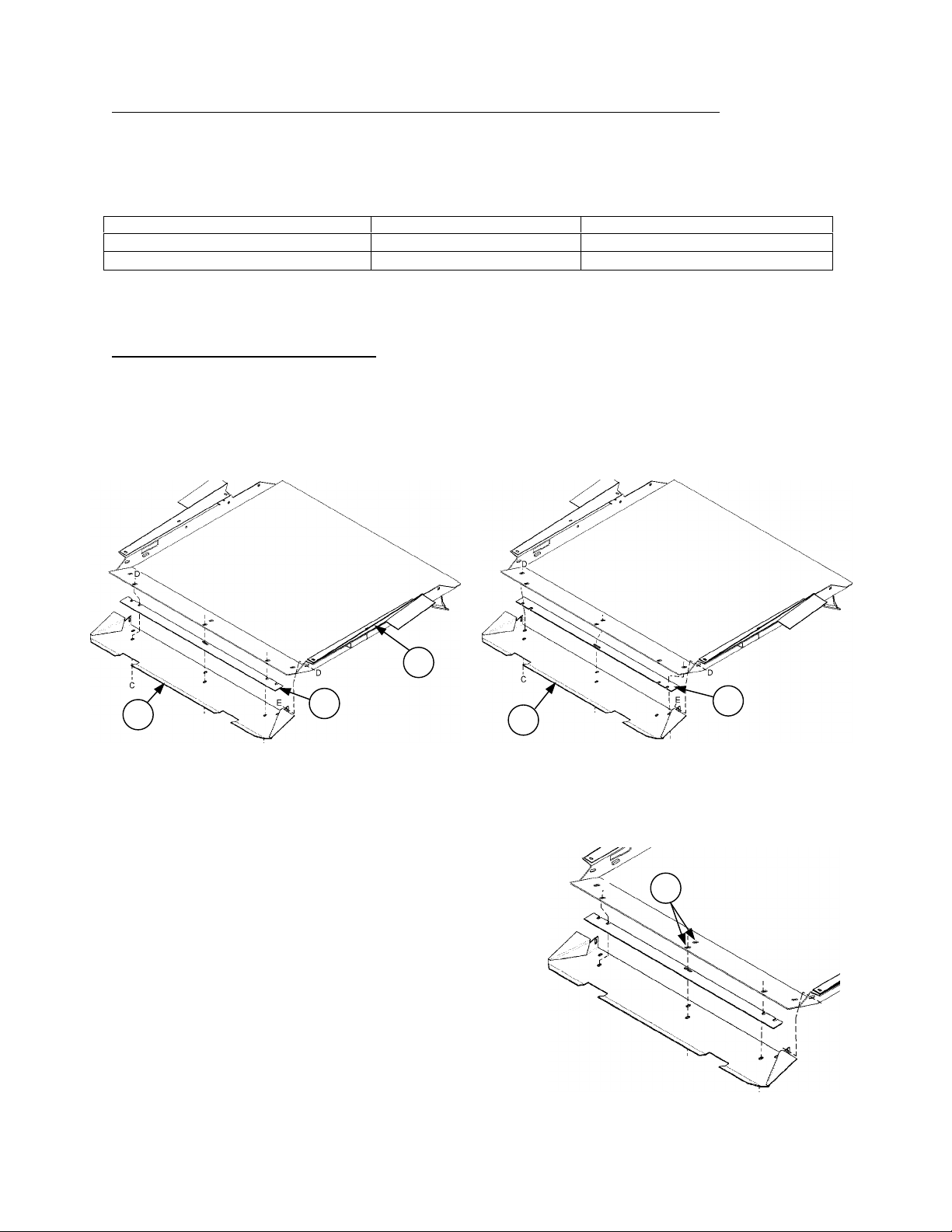
Page 30

ASSEMBLY
INSTALL 962 HEADER COMPLETION PARTS
NOTE: This page applies to Model 962 Header only.
1. Deck backsheet extensions (C) and (D) are in the
Header Completion package that cam e with the
Combine Adapter. These are installed at the
delivery opening.
Install extension (C) on left side of delivery
opening and (D) on right side. Extensions mount
to rear of deck backsheet with 3/8 x 3/4 bolts and
flange locknuts. Install hardware with bolt heads
on draper side.
2. Retainers (E) are shipped with the Combine
Adapter. These are installed inside header
center legs to secure header to adapter when
full float is reached. Retainers also restrict
side movement.
Install retainer (E) at inside of left center leg,
using existing 0.41 x 0.81" slot. Secure with
3/8 x 3/4 carriage bolt (F) and f lange loc knut
(G). When tightening, ensure that header pin
fits freely through leg and retainer at (X).
NOTE: L/H leg is shown. Retainer (E) mounts
to leg side wall closest to center delivery
opening. Left and right retainers (E) are
different. Be sure they are correctly
positioned.
Repeat at right center leg.
3. For delivery openings of 41.7” (1060 mm) and
smaller, install draper supports (A) at cutterbar
side of idler roller bars using 3/8 x ¾ carriage head
bolts and flange nuts.
For larger openings, remove supports (A), if
installed.
A
30
Page 31

ASSEMBLY
INSTALL HEADER SIDE DRAPE RS & SET DECK DEFLECTORS
1. Connect side drapers according to your Header Operator’s Manual or Set-Up Instructions.
IMPORTANT: Cut off any excess flap only after drapers have been connected and tensioned and overlap
at sides of feed draper deck has been checked.
2. For proper feeding in most crops, the header side draper idler rollers should be set to an opening of:
59.5” (1510 mm) for wide deck adapters: John Deere 9600/9610/9650 and Cat 460 & 480 Series
53.5” (1360 mm) for wide deck adapters: John Deere STS/CTS/9500/9510 and New Holland TX
49.6” (1260 mm) for mid-size deck adapters: Cat 450 & 470 Series
41.7” (1060 mm) for mid-size deck adapters: Case 80 & 88 Series
37.4” (950 mm) for narrow deck adapters on 972 Headers: Case 60 & 66 Series, Gleaner &
New Holland TR
33.9” (860 mm) for narrow deck adapters on 962 Headers: Case 60 & 66 Series, Gleaner &
New Holland TR
In some cases, actual opening size will be
varied by re-positioning deck on one side to
properly overlap and align with feed draper. See
plasticized Set-Up card provided.
NOTE: Side deflectors (A) and rear deflectors
(B) are factory set for an opening width to
correspond to the feeder house opening for a
specific model of combine, according to the
following chart.
The rear vertical edge of the deflectors (B)
should just fit inside feeder hous e opening. If
factory setting is not correct for your model of
combine, loosen two bolts (C) and adjust rear of
deflector to suit feeder house opening.
REAR
COMBINE MAKE & MODEL
Case 60 & 66 Series 37” (940 mm)
Case 80 & 88 Series 43.7” (1110 mm)
John Deere 9600, 9610, 9650 * 60.2” (1530 mm)
JD CTS/STS, Contour Master,
9500 & 9510 *
New Holland TR & Gleaner 38.2” (970 mm)
New Holland TX * 54.9” (1395 mm)
Cat Lexion 450 & 470 Series 47.6” (1210 mm)
Cat Lexion 460 & 480 Series * 59” (1500 mm)
DEFLECTORS
OPENING WIDTH
54.9” (1395 mm)
NOTE: For wide deck adapters (thos e with * above),
the rear deflector setting is dictated by the position of
the plastic closure panel. See page 34.
A
B
NARROW DECK ADAPTERS
C
A
B
C
MID-SIZE DECK ADAPTERS
B
C
A
WIDE DECK ADAPTERS
31
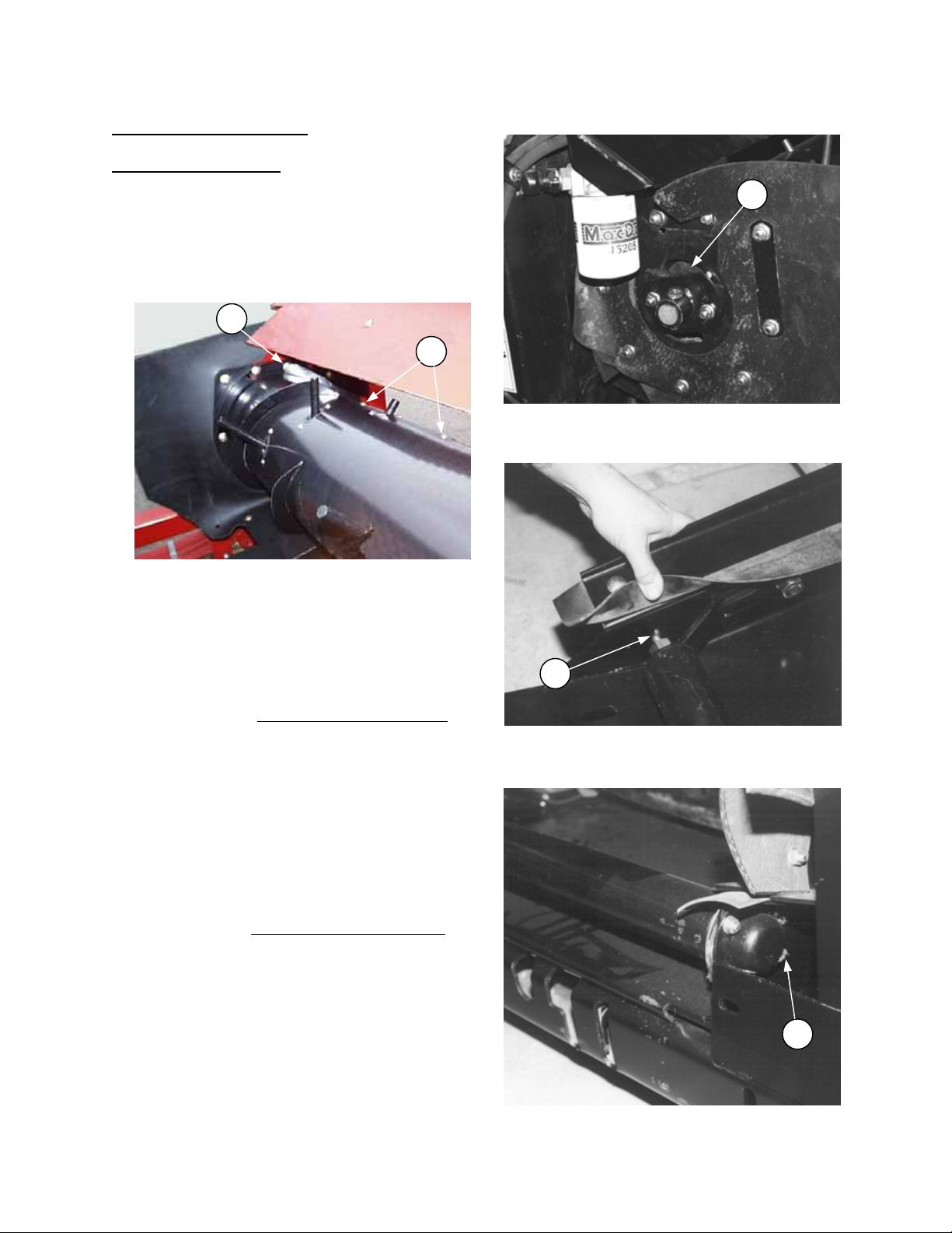
Page 32

APPLY DRAPER TENSION &
ASSEMBLY
ADAPTER PREPARATION
1. Remove shipping brace (painted yellow) and parts strapped to adapter.
2. Install pump in storage position. (See Mounting Instruction for your combine, beginning on page 37.)
NOTE: Wear gloves when handling pump.
INSTALL FEED DRAPER ON COMBINE ADAPTER
1. Loosen nut (G), both sides, and pull up on idler
roller to rotate to position (A). Nut (G) must be
loose enough that idler arm easily passes by
adjusting rod (J).
NOTE: Rod (J) may come out of position when
lifting idler roll er. It will return to proper posi tion
when roller is moved to working position (B).
Try moving idler roller from position (A) back to
working position (B). If roller does not pivot
over, loosen bolt (G) further. W hen nut ( G) is
properly loosened, pull roller up to position (A)
for installation of draper.
2. Install feed draper on a dapter rollers, ensuring
belt on underside seats properly on left side of
both rollers.
3. Pre-install screws (F) in connector slat. Screws
fit tightly into slat holes. To install, support slat
on both sides of hole and hamm er screw into
hole. Position connector slats (D) as shown
with heads leading in direction of travel.
FEEDER DRAPER CONNECTION
4. Apply draper tension as follows:
a. With nut (G) loosened per step 1, swing roller
from position (A) to working position (B),
standing on ends of roller if necessary. Take
care not to damage roller or draper seal.
b. Back off nut (H) and adjust position of nut (C)
to align bracket with welded channel as shown.
This position provides proper spring tension.
Tighten nut (H) against nut (C) to secur e the
position. Repeat at other side.
c. Tighten nut (G), both sides, ensuring that
formed end of adj usting rod seats properly in
pocket formed into idler arm and that rod is
positioned at bottom of cut-out in side of pan.
INSTALL SKID PLATE ON ADAPTER
FEED PAN
962 Header – Attach skid plate to adapter feed
pan, using ½ x 1 carriage bolts and flange nuts as
shown. Position hardware at front of slots and
leave finger tight. When attaching to header,
adjust clearance to cutterbar as described on page
9.
972 Header – Attach pa n (K) and space r plat e (L)
to adapter feed pan, using three ½ x 1 ¼ carriage
bolts (M) and lock nuts to attach through spacer
plate. Elsewhere use ½ x 1 carriage bolts (N) and
lock nuts to attach pan (K) to adapter feed pan.
Slide pan (K) forward and finger tighten hardware
to lightly clamp parts.
NOTE: Spacer plate (L) can be repositioned if
more clearance to header drapers is required. See
page 17.
962 SKID PLATE
INSTALL 962 SKID PLATE
L
M
N
K
INSTALL SKID PLATE – 972 HEADERS
32
Page 33

ASSEMBLY
MECHANICAL CENTER LINK
ATTACH CENTER LINK
For mechanical center link (G), attac h to adapter
frame with clevis and lynch pins as shown, with
locking collar (H) forward and pointing upward.
For hydraulic center link:
1) Attach quick-couplers (not included in cylinder kit)
matching the type on your combine to end of
hoses.
NOTE: Coupler completion kits ar e available for
each combine. See completion k it numbers in
illustration below.
Use the O-ring (A) (provided in cylinder kit) on the
3/8 tube thread of the selected adapter fitting.
This connects into shut-off valve for proper seal.
2) Attach cylinder assembly as follows:
a) Orient cylinder with hoses routed towards header.
b) Attach cylinder to adapter with 1-inch dia. clevis pin (B) and lynch pin.
c) With adapter connected to combine, connect couplers to combine hydraulics.
d) Drive combine close enough to header and extend or retract cylinder to allow attaching cylinder to
header with 1-inch dia. clevis pin (C) and lynch pin.
e) Route hoses along header tube and secure with clamp (F), using 3/8 x 3/4 carriage bolt and nut for
962 header and 3/8 x 5/8 thread rolling screw for 972 header.
3) When detaching adapter from combine, before disconnecting quick couplers, turn off oil flow at shut-off
valve (E). This allows ea si er reat ta chment of coup le rs at combine. Re member to restore oil flow at shutoff valve before next use.
33
Page 34

ASSEMBLY
MID-SIZE DECKS
POSITION THE RETRACTING TINE DRUM
Adapters (except JD Contour Master and Gleaner)
are shipped with drum fore-aft position at
dimension (X or Y) shown in chart. This is
measured from the adapter frame leg to the center
of the drum. This position ensures clearance to the
combine feeder house.
IMPORTANT: For best performance, when
adapter is attached to combine, ensure that
clearance between adapter drum and combine
feed drum ranges f rom 1 to 2 inches (25 to 50
mm), with combine feed drum floated up. Rotate
adapter drum rearward if required to achieve this
dimension. For JD Contour Master rotate drum
forward so Y = 8 ¼” (210 mm) to clear wel ded du st
shields. For Gleaner, rotate drum back so X = 3.9”
(100 mm).
To adjust drum fore-aft position, loosen two
mounting bolts (B) each side and swing drum foreaft in rear slot. Tighten bolts to secure the position.
Combine Make & Model Dimension X
Case 5.9” (150 mm)
New Holland TR 6.5” (165 mm)
Gleaner R62 & R72 3.9” (100 mm)
Cat – Lexion 450, 470 & 475 4.1” (105 mm)
REMOVE DUST
SHIELDS
B
DRUM FORE-AFT ADJUSTMENT
Combine Make & Model Dimension Y Panel*
John Deere Level Land, CTS, STS 6.9” (175 mm) D
John Deere Contour Master 8 ¼“ (210 mm) F
John Deere 9600, 9610, 9650 6.9” (175 mm) F
New Holland TX 6.9” (175 mm) D
Cat – Lexion 460, 465, 480 &485 6.3” (160 mm) E
* NOTE: Panel positions D, E & F indicate hardware
positioning for securing plastic closure panels.
REMOVE DUST
SHIELDS
IMPORTANT: With opening sizes required for some combines, to avoid damage to header, it will be
necessary to remove one tine from each end of retracting tine drum. See plasticized Set-Up card provided.
(25 to 50 mm)
RTD POSITIONING – NARROW &
DRUM
FLOATED UP
1” to 2”
DRUM
FLOATED UP
1” to 2”
(25 to 50 mm)
RTD POSITIONING –WIDE DECKS
34
Page 35

ASSEMBLY
ELECTRICAL HARNESS
Attach electrical harness extension, (shipped with adapter) to your header wiring harness. This allows
connection to combine harness for operation of amber lights on header.
NOTE: For combines that do not have a harnes s connector for feeder house attachm ents, order W iring
Harness (MacDon Part No. 40435), and splice into combine harness as follows:
Dark Blue Wire: to L/H turn signal circuit
Light Blue Wire: to R/H turn signal circuit
Black Wire: to Ground
NOTE: If combine will be used with Hydraulic Deck Shift Header for end delivery windrowing, order B-2407
Harness and Support for deck shift switch. Installation instructions are included with the package. The deck
shift switch is supplied with the Hydraulic Deck Shift Header.
NOTE: Some combine adapter wiring harnesses are supplied with circuits for special functions such as:
• Reel Speed Sensor
• Reel Height Sensor
• Header Height Sensor
The routing of these harnesses for 962 and 972 Headers is described on the Installation Instructions
provided with the sensor kits. For 972 headers, holes for harness clips are not provided in some headers.
For these headers, drill two 0.343” (11/32”) holes as shown below:
HARNESS ENTERS
CHANNEL HERE
CUT-OUT IN CHANNEL UNDER
HARNESS EXITS CHANNEL HERE FOR
SENSORS AT CENTER OF HEADER
(HOLES MEASURED FROM OUTBOARD
EDGE OF THIS CUT-OUT)
DRILL TWO 11/32 HOLES
FOR HARNESS CLIPS AT
DIMENSIONS BELOW
HEADER FRAME TUBE
HARNESS EXITS CHANNEL
HERE FOR SEN S ORS AT R/H
END OF HEADER
280 mm
(11”)
580 mm
(22.8”)
70 mm
(2 ¾”)
35
Page 36

ASSEMBLY
ATTACH ADAPTER TO COMBINE
Attach combine adapter to feeder housing of combine. See Mounting Instructions for your particular make of
combine on the following pages:
John Deere - page 37 Case IH - page 42 Gleaner - page 48
New Holland - page 55 Cat Lexion – page 62
NOTE: If a combine is not available, adapter can be attached to header with use of a forklift. See instruction
on page 68.
ATTACH HEADER
CAUTION: Read the Operator’s Manuals carefully to familiariz e your self with procedure s and
controls before attaching header to combine.
NOTE: Hydraulic hose lengths and couplings are provided based on the latest available inform ation from
combine manufacturers. Should these not be suitable for a particular model or production series, modify or
purchase the necessary components.
See page 6 for "Attaching Header to Combine".
See Header Operator's Manual for assembly instructions not related to the adapter.
ADJUSTMENTS & CHECKS
1. Remove steel backsheet ex tensions for all 972 Headers. For 972 Headers on Case, New Holland T R,
Gleaner, or Cat 450/470/475 combines (11” Retracting Tine Drum), trim rubber closure flaps at (A) to fit
the shape of the header back tube. NOTE: Trim with center link adjusted to shortest operating position.
A
A
TRIM CLOSURE FLAPS ON 972 HEADERS
Case, New Holland TR, Gleaner, or Cat 450/470/475
2. Check that feed draper rear roller moves up and down freely.
3. Run drapers slowly for 5 minutes to fill hydraulic lines, then check oil level at adapter reservoir.
Perform final adjustments and checks as listed on the "Pre-Delivery Checklist" (yellow inserts) in this manual
and the Header Operator's Manual to ensure the machine is field-ready.
36
Page 37

Adapter Mounting Instructions
INSTALL REEL LIFT HOSE - 962 HEADER
for John Deere Combines
PREPARING THE HEADER
1. Mount reel lift coupler assembly (F) to outside
of left header leg wit h t w o 3/8 NC x 3/4 carri age
bolts and flange nuts as shown.
Connect header reel lift hose to reel lift coupler
assembly (F).
962 Header only: Attach reel lift hose (from
header completion pack age) at left of delivery
opening as follows:
For 30’ headers the reel lift hose connects to
hydraulic line (D).
For 36’ headers the reel lift hose connects to
hose (E).
2. Attach driveline supplied wi th adapte r to hea der
sickle drive shaft. Sec ure clam p yoke to shaft
with 1/2 NC hardware provided.
KF
For storage, attach other end of driveline to
anchor (K) provided on reel lift coupler
mounting bracket (F) installed in step 1.
3. Single Sickle:
Bolt the sheet metal p ulley (A) pro vi ded with the
adapter on the sickle drive pulley (962) or drive
hub (972) at the left end sheet, using three 3/8
x 1 bolts with lock washers.
Double Sickle 972:
See 972 Operators Manual “Unloading and
Assembly” section.
4. Install wiring harness extension provided with
adapter onto header wiring harness.
NOTE: Two harnesses are provided. The
harness with the small diameter c onnector is
for combines prior to 50 Series. T he harnes s
for 50 Series combines has a larger diam eter
connector. If combine does not have an
electrical connector, see page 35.
INSTALL REEL LIFT COUPLER
A
INSTALL SICKLE DRIVE PULLEY
37
Page 38

Adapter Mounting Instructions
for John Deere Combines
PREPARING THE ADAPTER
1. Level Land Prior to 50 series F eeder House:
Install pump torque arm support (A) to bolt
welded to R/H frame member of adapter using
3/4” locknut at (K). Orient support as shown.
Contour Master and 50 series Level Land
Feeder House: Install pump torque arm
support (B) to bolt welded to R/H frame
member of adapter using 3/4” loc knut at (L).
Orient support as shown.
NOTE: For 9650 Combine, bolt torque arm (C)
(with two bends) to existing torque arm using
three M12 x 30 bolts.
INSTALL PUMP TORQUE ARM SUPPORT
2. Attach locking c hannels (H) to adapter fram e,
using locking bar (J) between channel and lock
nuts. Install channels with single-hole leg
outboard and narrower clearance to bottom on
two-hole leg as shown.
NOTE: Lock pins at bottom of combine feeder
house engage these channels. Adjust position
of channels (H) by loosening hardware and
sliding channels up and down for proper
alignment.
3. Level Land Prior to 50 series Feeder House:
Attach shield (D) to left side of adapter fr ame
with 5/16 x 3/4” flange bolt and nut.
NOTE: Install nut “upside down”, that is, with
serrated flange down, so flats of hex engage in
slot in adapter frame.
NOTE: For 9600 and 8820 combines, shield
(G) is not required. Remove prior to installation
of shield (D). Swing shield (D) forward for end
transport situations.
4. Contour Master only: Add float range limiters to
prevent damage to the retracting tine drum
and/or header side drapers when operating at
flat header angles. See instruction on page 71.
5. Contour Master only: Trim plastic closure
panels as shown at right (shaded area). Leave
panels off of adapter until just before adapter is
completely installed in header.
J
H
INSTALL LOCKING CHANNELS
G
D
ATTACH L/H SHIELD: LEVEL LAND
95 mm
(3-3/4”)
Trim Line
6. Contour Master only: Move retracting tine drum
forward from the factory installed position to as
shown on page 34. NOTE: To avoid damage
to the tine drum and/or com bine, leave drum
mounting hardware loose until the
combine/adapter/header package is fully
together. Adjust center link (connecting header
to adapter) to minimum length, float header up,
then tighten drum mounting hardware.
7. 9500/10,CTS/II, STS and CT S 50 Series: To
avoid damage to header, remove one tine from
each end of retracting tine drum.
370 mm
(14-1/2”)
38
325 mm
(12-3/4”)
Trim Line
190 mm
(7-1/2”)
TRIM PLASTIC PANELS
CONTOUR MASTER ONLY
Page 39

Adapter Mounting Instructions
SPLINE SHAFT & CLAMP
for John Deere Combines
PREPARING THE COMBINE
1. Check with Combine dealer to ensure combine is
equipped with tire size, rear ballast etc. to carry
larger headers.
2. IMPORTANT: To prevent damage to feeder house
and/or adapter feed drum, remove all feeder house
dust shields (A), closure panels etc. that are
removable.
NOTE: Contour master dust shield is not
removable. The adapter feed drum must be moved
forward to compensate for this. See page 34.
Contour master filler plates (G) should be removed.
3. Lock pin (B) both sides must be in retracted position
before attaching adapter.
4. For models with variable speed feeder house drive,
set header output shaft speed to 520 rpm.
5. Set feeder chain to high speed. For older combines,
additional chain links will be required to move chain
to larger sprocket at (E). On newer combines the
adjustment range allows for this repositioning. Refer
to Combine Operator’s Manual.
6. Contour Master: To improve performance, move
feeder chain as far forward as possible by adding
links.
7. Adjust combine feed drum height to GRAIN position.
Refer to Combine Operator’s Manual.
8. Level Land Prior to 50 Series Feeder House: Attach
spline shaft provided with adapter to feeder house
L/H output drive as follows:
7720, 9500, 9510 & CTS
a. Remove existing sprocket coupler.
b. Ensure that the three 3 inch long bolts (C) are just
tight enough to eliminate gaps between parts, but
no tighter.
c. Position spline shaft & clamp assembly onto shaft
and tighten the two 4-½ inch long bolt s (D ) evenly to
80 ft.lbs. (110 N·m).
d. Tighten the three 3 inch long bolts (C) to 80 ft.lbs.
(110 N·m).
8820, 9600 & 9610
a. Remove the three 3 inch long bolts connecting
spline shaft (F) to clamp halves.
b. Attach spline shaft (F) directly to sprocket with three
½ x 1-¼ bolts and flange nuts provided.
E
B
LOCK PINS RETRACTED
G
REMOVE CONTOUR MASTER
COMBINE FILLER PLATES
A
REMOVE
LEVEL LAND PRIOR TO 50 SERIES:
F
8820, 9600 & 9610
ATTACH SPLINE SHAFT
39
D
LEVEL LAND PRIOR TO 50 SERIES:
7720, 9500, 9510 & CTS - ATTACH
C
Page 40

Adapter Mounting Instructions
PUMP IN WORKING POSITION
for John Deere Combines
ATTACHING ADAPTER TO COMBINE
1. Slowly drive combine up to ada pter until lift lugs
(C) are directly under adapter top cross
member.
2. Raise feeder house to lift adapter, ensuring lift
lugs are properly engaged. Raise adapter fully.
WARNING: To avoid bodily injury or
death from unexpected start-up or
fall of raised attachment; stop
engine, remove key and engage lift cylinder
stop before proceeding with hook-up.
3. Engage lock pins (E) in adapte r brackets, both
sides.
4. Install pump as follows:
NOTE: Wear gloves when handling pump.
a. Remove pump from storage position (A) on
adapter and slide pump onto R/H feeder house
output shaft.
NOTE: The first time the pump is installed,
hoses may have to be loosened for proper
alignment. Tighten hoses after installation.
C
ALIGN LIFT LUGS UNDER ADAPTER FRAME
b. Engage pump torque arm on support arm on
adapter and secure with lynch pin at (B).
NOTE: For 9650 combine, ensure torque arm
(C) with 2 bends has been added to pump
assembly. See page 38, Step 1.
5. Tighten combine feeder chain and check
clearances. See page 39, step 5.
A
PUMP STORAGE ON ADAPTER
E
ENGAGE LOCK PINS - BOTH SIDES
40
Page 41

Adapter Mounting Instructions
COMBINE TO HEADER CONNECTIONS, R/H SIDE
for John Deere Combines
ATTACHING ADAPTER TO COMBINE (continued)
COMBINE TO HEADER CONNECTIONS -
LEFT SIDE
PUMP MOUNTING –
CONTOUR MASTER & 50 SER. LEVEL LAND
PUMP MOUNTING – PRIOR TO 50 SERIES &
41
Page 42

Adapter Mounting Instructions
ATTACH REEL DRIVE MOUNTING PLATE
ROUTE REEL DRIVE HOSES – 30’ 962
ROUTE REEL DRIVE HOSES – 36’ 962
for Case IH Combines
PREPARING THE HEADER
1. Attach the reel drive plumbing as follows:
962 Headers: (see next page for 972)
a. 30 ft. 962 Header: Remove the existing mount
for the reel drive couplers at right header leg.
Remove the two hoses connecting the couplers
to steel lines.
36 ft. 962 Header: Detach the two rear hoses
inside center reel arm (connected to hoses
leading to the reel drive motor). Rem ove rear
hoses, couplers and mounting plate.
b. Attach the reel drive mounting plate (A),
provided with the adapter, to the left header leg
with two 3/8 x 3/4 carriage bolts and flange
nuts.
A
TO HEADER L/H LEG
c. Route reel drive hoses f rom assem bly (A) as
follows:
30’ 962 Header - Attach hoses to lines at (B),
matching yellow cable ties. Rout e hoses along
back tube as shown and secure with four
clamps. Use two 3/8 x 5/8 hex washer head
machine screws at (C) and two 3/8 x ¾
carriage bolts at (D). (Use one carriage bolt
from reel drive coupler mounting plate removed
above. Other parts and hardware supplied with
header completion package.)
36’ 962 Header - Attach hoses to hoses inside
center reel arm leading to the reel driv e motor,
matching yellow cable ties. Rout e hoses along
back tube as shown and secure with three
clamps. Use two 3/8 x 5/8 hex washer head
machine screws at (E) and one 3/8 x ¾
carriage bolt at (F).
D
F
C
D
B
E
42
Page 43

Adapter Mounting Instructions
PREPARING THE HEADER
for Case IH Combines
1. Attach the reel drive plumbing as follows:
972 Headers: (see previous page for 962)
a. Headers with 2-Arm Reel: Remove the existing
mount for the reel drive couplers at right
header leg. (Remove the two elbo w s alon g with
the couplers and mount.)
Headers with 3-Arm Reel: Detach the two
hoses at the reel drive motor, and remove the
couplers and mounting plate.
b. Route reel drive hoses from assembly (A)
(provided with the adapter) as follows:
Headers with 3-Arm Reel - Attach hoses to reel
drive motor. Hose with yellow cable tie goes to
bottom port of motor. Route hoses along back
tube and secure with clamps and hardware
provided with header completion package,
similar to 962 36’ Header shown on previous
page.
Headers with 2-Arm Reel
- Hydraulic Deck Shift Headers only: Route
hose from mounted coupler between deck shift
hoses and L/H header leg.
- All 2-Arm Headers: Remove the draper drive
hose clamps (H), both sides, and clamp (G) to
allow reel drive hoses to be guided past. Push
hoses through channel (F) across header
opening to the R/H side. This will be easier if
hoses being pushed through are at back of
channel (F) (rearward of other hoses in
channel). Connect to header reel dri ve h oses at
(J), matching the yellow cable ties. After
connection, pull hoses back through on L/H
side to position shown in bottom photo. Pull
excess header hose on R/H side toward reel
drive for best appearance.
- Replace clamps (H) and (G) on draper drive
hoses.
G
REMOVE DRAPER DRIVE HOSE CLAMP
J
F
H
REEL DRIVE HOSES – R/H SIDE
F
H
c. Attach the reel drive mounting plate (A) to the
left header leg with two 3/8 x 3/4 carriage bolts
and flange nuts.
A
ATTACH REEL DRIVE MOUNTING PLATE
TO HEADER L/H LEG
43
Page 44

Adapter Mounting Instructions
for Case IH Combines
PREPARING THE HEADER (continued)
2. Connect the male coup ler with 1/4 NPT a dapt er
(from combine adapter package) to the reel lift
hose on the header.
962 Header only: Attach reel lift hose (from
header completion pack age) at left of delivery
opening as follows:
For 30’ headers the reel lift hose connects to
hydraulic line (D).
For 36’ headers the reel lift hose connects to
hose (E).
3. Attach driveline supplied wi th adapte r to hea der
sickle drive shaft. Sec ure clam p yoke to shaft
with 1/2 NC hardware provided.
For storage, attach other end of driveline to
anchor (K).
INSTALL REEL LIFT HOSE - 962 HEADER
K
4. Single Sickle:
Bolt the sheet metal p ulley (A) pro vi ded with the
adapter on the sickle drive pulley (962) or drive
hub (972) at the left end sheet, using three 3/8
x 1 bolts with lock washers.
Double Sickle 972:
See 972 Operators Manual “Unloading and
Assembly” section.
5. Install wiring harness extension provided with
adapter onto header wiring harness.
NOTE: If combine does not have an electrical
connector, see page 35.
DRIVELINE STORAGE LOCATION
A
INSTALL SICKLE DRIVE PULLEY
44
Page 45

Adapter Mounting Instructions
for Case IH Combines
PREPARING THE ADAPTER
1. Install feeder house support (C) (from adapter
package) onto the adapter frame with one
1/2 x 1 flange bolt at (D) and three 1/2 x 1
carriage bolts and flange nuts at (E). Repeat at
other side.
NOTE: For attachment to top beam, engage
carriage bolts in keyhole slots.
2. Attach filler (F) with one 1/2 x 1¼ carriage bolt
and flange nut. Repeat at other side.
NOTE: Filler (F) shown is for 60 & 66 Series
Combines. A similar, shorter piece is used with
the mid size deck used with 80 & 88 Series
Combines
3. Install lower latch pivot bars (B) in adapter
frame. Ensure pivot pin is installed inside frame
in high position as shown.
D
E
C
F
B
INSTALL ADAPTER COMPLETION PARTS
45
Page 46

Adapter Mounting Instructions
ALIGN FEEDER SADDLE UNDER
PREPARING THE COMBINE
for Case IH Combines
1. Check with Combine dealer to ensure combine
is equipped with tire size, rear ballast etc. to
carry larger headers.
2. For 36 foot header on 1460, 1480, 1660 and
1680 combines, install optional third feeder
house lift cylinder. Order numbers:
Feed House Lift Cylinder Kit: Kind - 172, Code
- 1092
Accumulator Kit: Kind - 172, Code – 1084
3. Remove dust shield across top of feeder
house opening to allow positioning of adapter
feed drum as shown on page 34.
4. Remove shield f rom R/H feeder house output
shaft and replace with shield (A) and drive arm
support (D) provided with adapter. T his shield
can be hinged out of the way for MacDon
adapter and swung back into place for pick-up
header.
NOTE: For narrower feeder house combines
(1640, 1644, 1660, 1666, 2166 and 2366) also
install shield extension (E).
5. Install shield (B) on L/H feeder house output
shaft shield with 3/8 x 5/8 flange bo lt a nd nut as
shown.
D
A
HINGED R/H SHIELD
E
D
B
L/H SHIELD
6. Set feeder house face plate, feeder chain and
drum height as shown on Quick Reference
Card.
ATTACHING ADAPTER TO COMBINE
1. Slowly drive combine up to adapter until feeder
saddle (C) is directly under adapter top cross
member.
2. Raise feeder house to lift adapter, ensuring
feeder saddle is properly engaged in adapter
frame. Raise adapter fully.
WARNING: To avoid bodily injury or
death from unexpected start -up or fall
of raised attachment; stop engine,
remove key and engage lift cylinder
stop before proceeding with hook-up.
A
HINGED R/H SHIELD – NARROW FEEDERS
C
ADAPTER FRAME
46
Page 47

Adapter Mounting Instructions
for Case IH Combines
ATTACHING ADAPTER TO COMBINE (continued)
3. Lower latch handle (E) (one each side of feeder
house) to hook pivot bar (F). Lift handle to ov ercenter position to lock. It should take 40 to 50
lbs. force (180 to 220 N) to move handle overcenter. Adjusting the torque of bolts (G) will
vary the handle force required. W hen handle
force is correct, tighten jam nuts (K).
4. Install pin (H) as shown to secure the latch
handle in locked position.
5. Install pump as follows:
NOTE: Wear gloves when handling pump.
E
H
F
K
G
ENGAGE LOCKS - BOTH SIDES
a. Remove pump from storage position (A) on
adapter and slide pump onto R/H feeder house
output shaft.
NOTE: The first time the pump is installed,
hoses may have to be loosened for proper
alignment. Tighten hoses after installation.
b. Engage pump torque arm on support arm on
adapter and secure with lynch pin at (B).
A
PUMP STORAGE ON ADAPTER
B
47
PUMP IN WORKING POSITION
Page 48

Adapter Mounting Instructions
ROUTE REEL DRIVE HOSES – 30’ 962
ROUTE REEL DRIVE HOSES – 36’ 962
ATTACH REEL DRIVE MOUNTING PLATE
for Gleaner Combines
PREPARING THE HEADER
1. Attach the reel drive plumbing as follows:
962 Headers: (see next page for 972)
a. 30 ft. 962 Header: Remove the existing mount
for the reel drive couplers at right header leg.
Remove the two hoses connecting the couplers
to steel lines.
36 ft. 962 Header: Detach the two rear hoses
inside center reel arm (connected to hoses
leading to the reel drive motor). Rem ove rear
hoses, couplers and mounting plate.
b. Attach the reel drive mounting plate (A),
provided with the adapter, to the left header leg
with two 3/8 x 3/4 carriage bolts and flange
nuts.
c. Route reel drive hoses f rom assem bly (A) as
follows:
A
TO HEADER L/H LEG
30’ 962 Header - Attach hoses to lines at (B),
matching yellow cable ties. Rout e hoses along
back tube as shown and secure with four
clamps. Use two 3/8 x 5/8 hex washer head
machine screws at (C) and two 3/8 x ¾
carriage bolts at (D). (Use one carriage bolt
from reel drive coupler mounting plate removed
above. Other parts and hardware supplied with
header completion package.)
36’ 962 Header - Attach hoses to hoses inside
center reel arm leading to the reel driv e motor,
matching yellow cable ties. Rout e hoses along
back tube as shown and secure with three
clamps. Use two 3/8 x 5/8 hex washer head
machine screws at (E) and one 3/8 x ¾
carriage bolt at (F).
D
F
C
D
B
E
48
Page 49

Adapter Mounting Instructions
for Gleaner Combines
PREPARING THE HEADER
1. Attach the reel drive plumbing as follows:
972 Headers: (see previous page for 962)
a. Headers with 2-Arm Reel: Remove the existing
mount for the reel drive couplers at right
header leg. (Remove the two elbo w s alon g with
the couplers and mount.)
Headers with 3-Arm Reel: Detach the two
hoses at the reel drive motor, and remove the
couplers and mounting plate.
b. Route reel drive hoses from assembly (A)
(provided with the adapter) as follows:
Headers with 3-Arm Reel - Attach hoses to reel
drive motor. Hose with yellow cable tie goes to
bottom port of motor. Route hoses along back
tube and secure with clamps and hardware
provided with header completion package,
similar to 962 36’ Header shown on previous
page.
Headers with 2-Arm Reel
- Hydraulic Deck Shift Headers only: Route
hose from mounted coupler between deck shift
hoses and L/H header leg.
- All 2-Arm Headers: Remove the draper drive
hose clamps (H), both sides, and clamp (G) to
allow reel drive hoses to be guided past. Push
hoses through channel (F) across header
opening to the R/H side. This will be easier if
hoses being pushed through are at back of
channel (F) (rearward of other hoses in
channel). Connect to header reel dri ve h oses at
(J), matching the yellow cable ties. After
connection, pull hoses back through on L/H
side to position shown in bottom photo. Pull
excess header hose on R/H side toward reel
drive for best appearance.
- Replace clamps (H) and (G) on draper drive
hoses.
G
REMOVE DRAPER DRIVE HOSE CLAMP
J
F
H
REEL DRIVE HOSES – R/H SIDE
A
c. Attach the reel drive mounting plate (A) to the
left header leg with two 3/8 x 3/4 carriage bolts
and flange nuts.
49
F
H
ATTACH REEL DRIVE MOUNTING PLATE
TO HEADER L/H LEG
Page 50

Adapter Mounting Instructions
962 HEADER
for Gleaner Combines
PREPARING THE HEADER (continued)
2. Connect the 1/4 NPT male coupler assembly
(from combine adapter package) to the reel lift
hose on the header.
NOTE: Install reel drive holder (H) in retracted
position (shown), unless combine hos e is not
long enough to attach. Check this with header
on ground. In this case, a second hole is
provided in holder (H) to install in an extended
position.
972 Header: Remove existing reel lift hose
clamp at left header leg and attach coupler
assembly at this location.
962 Header: Attach reel lift hose (from header
completion package) at left of delivery opening
as follows: For 30’ headers the reel lift hose
connects to hydraulic line (D). For 36’ headers
the reel lift hose connects to hose (E).
Secure coupler assembly to left header leg by
attaching holder (H) with 3/8 x 3/4 carriage bolt
and flange nut.
H
INSTALL REEL LIFT COUPLER ASSEMBLY
972 HEADER
INSTALL REEL LIFT HOSE – 962 HEADER
3. Attach driveline supplied wi th adapte r to hea der
sickle drive shaft. Sec ure clam p yoke to shaft
with 1/2 NC hardware provided.
For storage, attach other end of driveline to
anchor on reel drive couplers m ounting plate
installed in step 1.
4. Single Sickle:
Bolt the sheet metal p ulley (A) pro vi ded with the
adapter on the sickle drive pulley (962) or drive
hub (972) at the left end sheet, using three 3/8
x 1 bolts with lock washers.
Double Sickle 972:
See 972 Operators Manual “Unloading and
Assembly” section.
5. Install wiring harness extension provided with
adapter onto header wiring harness.
NOTE: If combine does not have an electrical
connector, see page 35.
H
INSTALL REEL LIFT COUPLER ASSEMBLY
A
INSTALL SICKLE DRIVE PULLEY
50
Page 51

Adapter Mounting Instructions
PREPARING THE ADAPTER
for Gleaner Combines
1. Install upper beam (1) (from adapter package)
onto the adapter frame with two 1/2 x 1 flange
bolts (E) (one each side) and four 1/2 x 1
carriage bolts (C) and flange nuts (D) (two
each side).
NOTE: For attachment to adapter at top beam,
engage carriage bolts (C) in keyhole slots.
2. Attach left member (2) with three 1/2 x 1
carriage bolts (C), one 1/2 x 1 f lange bolt (E)
and flange nuts (D). Repeat at right side.
3. Insert lower latch support (3) into oblong slot in
adapter frame as shown. Secure with 5/8 x
1-1/2 carriage bolt (F), flat washer (G) and nut
(H). Repeat at other side.
4. Install shields and other components.
A BOLT – round head, sq. neck, 3/8 NC x 3/4 in.
B NUT - lock, smooth flange, 3/8 NC dist. thread
C BOLT - round hd. short sq. nk, 1/2 NC x 1"
D NUT - lock, smooth flange, 1/2 NC dist. thread
E BOLT - flange head, 1/2 NC x 1 inch
F BOLT - rnd. hd. sq. neck, 5/8 NC x 1-1/2 inch
G WASHER - flat, 21/32 inch I.D.
H NUT - lock, 5/8 NC distorted thread
L BOLT - hex head, 5/8 NC x 1-1/2 inch
R BOLT - hex head, 3/8 NC x 1-1/2 inch
S WASHER - flat, 13/32 inch I.D.
T BOLT – round head, sq. neck, ½ NC x 1-1/4”
INSTALL ADAPTER COMPLETION PARTS
51
Page 52

Adapter Mounting Instructions
for Gleaner Combines
PREPARING THE COMBINE
1. For R62 combines, check with Combine dealer to ensure combine is equipped with tire size, rear ballast
etc. to carry larger headers.
2. Rotate feeder house latches back into the feeder
house.
3. Adjust R/H pivot shaft drive for grain. Position
belt on small drive sheave (top) and lar ge drive
sheave (bottom).
4. Adjust feed conveyor drum height to small grains
position as per combine operators manual.
5. Pre 1997 combines, tilt f eeder hous e fac e plate
¾ of the way back towards the cab. For 1998
and newer the faceplate is rigid and cannot be
tilted.
6. For models with variable speed feeder house
drive, set header output shaft speed to 620 rpm.
52
Page 53

Adapter Mounting Instructions
ALIGN TRUSS HOOKS
LOCK HOOKS INTO ADAPTER FRAME
for Gleaner Combines
ATTACHING ADAPTER TO COMBINE
1. Slowly drive combine up to adapter until feeder
house truss hooks (C) are directly under
adapter top cross member.
2. Raise feeder house to lift adapter, ensuring
truss hooks are proper ly engaged in adapter
frame. Raise adapter fully, allowing the lower
pins to penetrate the holes in the adapter back.
WARNING: To avoid bodily injury or
death from unexpected start-up or
fall of raised attachment; stop
engine, remove key and engage lift
cylinder stop before proceeding with
hook-up.
C
3. Insert concave door tool (E) in latch socket (F)
and rotate latch clockwise to lock hook s (G)
into the adapter frame (both sides). MAKE
CERTAIN that the latch is rotated over-center
to securely lock the hooks. If it does not latch,
check to determine if the lower pins (H) are
seated in the adapter back. If not, place a block
under the left end of the adapter and lower the
adapter to reseat the pins. Re -la tch th e ho oks.
4. Raise the adapter and lower it against the
ground a few ti mes to se tt l e t he ad ap t er on th e
feeder housing.
UNDER ADAPTER FRAME
H
G
BOTH SIDES
E
F
53
Page 54

Adapter Mounting Instructions
for Gleaner Combines
ATTACHING ADAPTER TO COMBINE (continued)
5. Install pump as follows:
NOTE: Wear gloves when handling pump.
a. Remove pump from storage position (A) on
adapter and slide pump onto R/H feeder house
output shaft.
NOTE: The first time the pump is installed,
hoses may have to be loosened for proper
alignment. Tighten hoses after installation.
b. Engage pump torque arm on support arm on
adapter and secure with lynch pin at (B).
6. Float the feeder house front drum up and
check for interference with adapter feed drum.
If so, remove a link f r om the feeder chain and
move the front drum back. Re-tighten chain
and check clearance again.
A
PUMP STORAGE ON ADAPTER
54
PUMP IN WORKING POSITION
Page 55

Adapter Mounting Instructions
ATTACH REEL DRIVE MOUNTING PLATE
ROUTE REEL DRIVE HOSES – 30’ 962
ROUTE REEL DRIVE HOSES – 36’ 962
for New Holland Combines
PREPARING THE HEADER
1. Attach the reel drive plumbing as follows:
962 Headers: (see next page for 972)
a. 30 ft. 962 Header: Remove the existing mount
for the reel drive couplers at right header leg.
Remove the two hoses connecting the couplers
to steel lines.
36 ft. 962 Header: Detach the two rear hoses
inside center reel arm (connected to hoses
leading to the reel drive motor). Rem ove rear
hoses, couplers and mounting plate.
b. Attach the reel drive mounting plate (A),
provided with the adapter, to the left header leg
with two 3/8 x 3/4 carriage bolts and flange
nuts.
A
c. Route reel drive hoses f rom assem bly (A) as
follows:
30’ 962 Header - Attach hoses to lines at (B),
matching yellow cable ties. Rout e hoses along
back tube as shown and secure with four
clamps. Use two 3/8 x 5/8 hex washer head
machine screws at (C) and two 3/8 x ¾
carriage bolts at (D). (Use one carriage bolt
from reel drive coupler mounting plate removed
above. Other parts and hardware supplied with
header completion package.)
36’ 962 Header - Attach hoses to hoses inside
center reel arm leading to the reel driv e motor,
matching yellow cable ties. Rout e hoses along
back tube as shown and secure with three
clamps. Use two 3/8 x 5/8 hex washer head
machine screws at (E) and one 3/8 x ¾
carriage bolt at (F).
TO HEADER L/H LEG
D
F
C
D
B
E
55
Page 56

Adapter Mounting Instructions
for New Holland Combines
PREPARING THE HEADER
1. Attach the reel drive plumbing as follows:
972 Headers: (see previous page for 962)
a. Headers with 2-Arm Reel: Remove the existing
mount for the reel drive couplers at right
header leg. (Remove the two elbo w s alon g with
the couplers and mount.)
Headers with 3-Arm Reel: Detach the two
hoses at the reel drive motor, and remove the
couplers and mounting plate.
b. Route reel drive hoses from assembly (A)
(provided with the adapter) as follows:
Headers with 3-Arm Reel - Attach hoses to reel
drive motor. Hose with yellow cable tie goes to
bottom port of motor. Route hoses along back
tube and secure with clamps and hardware
provided with header completion package,
similar to 962 36’ Header shown on previous
page.
Headers with 2-Arm Reel
- Hydraulic Deck Shift Headers only: Route
hose from mounted coupler between deck shift
hoses and L/H header leg.
- All 2-Arm Headers: Remove the draper drive
hose clamps (H), both sides, and clamp (G) to
allow reel drive hoses to be guided past. Push
hoses through channel (F) across header
opening to the R/H side. This will be easier if
hoses being pushed through are at back of
channel (F) (rearward of other hoses in
channel). Connect to header reel dri ve h oses at
(J), matching the yellow cable ties. After
connection, pull hoses back through on L/H
side to position shown in bottom photo. Pull
excess header hose on R/H side toward reel
drive for best appearance.
- Replace clamps (H) and (G) on draper drive
hoses.
G
REMOVE DRAPER DRIVE HOSE CLAMP
J
F
H
REEL DRIVE HOSES – R/H SIDE
F
c. Attach the reel drive mounting plate (A) to the
left header leg with two 3/8 x 3/4 carriage bolts
and flange nuts.
H
A
ATTACH REEL DRIVE MOUNTING PLATE
TO HEADER L/H LEG
56
Page 57

Adapter Mounting Instructions
for New Holland Combines
PREPARING THE HEADER (continued)
2. Connect the 1/4 NPT male coupler (from
combine adapter package) to the reel lift hose
on the header.
962 Header only: Attach reel lift hose (from
header completion pack age) at left of delivery
opening as follows:
For 30’ headers the reel lift hose connects to
hydraulic line (D).
For 36’ headers the reel lift hose connects to
hose (E).
3. Attach driveline supplied wi th adapte r to hea der
sickle drive shaft. Sec ure clam p yoke to shaft
with 1/2 NC hardware provided.
For storage, attach other end of driveline to
anchor (K).
INSTALL REEL LIFT HOSE - 962 HEADER
4. Single Sickle:
Bolt the sheet metal p ulley (A) pro vi ded with the
adapter on the sickle drive pulley (962) or drive
hub (972) at the left end sheet, using three 3/8
x 1 bolts with lock washers.
Double Sickle 972:
See 972 Operators Manual “Unloading and
Assembly” section.
5. Install wiring harness extension provided with
adapter onto header wiring harness.
NOTE: If combine does not have an electrical
connector, see page 35.
K
DRIVELINE STORAGE LOCATION
A
INSTALL SICKLE DRIVE PULLEY
57
Page 58

Adapter Mounting Instructions
for New Holland Combines
PREPARING THE ADAPTER
1. Install feeder house guide (1) (from adapter
package) onto the adapter frame with hardw are
shown. Repeat at other side.
2. Install lower feeder house beam (2) with
hardware shown. Position bolts against the
bottom of the slots in frame.
3. Install lower latch eyebolt assemblies (3) in
adapter frame.
4. Attach gearbox s upport (4) to c om bine f eeder
house as shown.
NOTE: Orientation of support depends on
combine model.
5. For TR Combines only, add float range limiters
to prevent damage to the retracting tine drum
and/or header side drapers when operating at
flat header angles. See instruction on page 71.
A BOLT - flange head, 1/2 NC x 1 inch
B NUT - smooth flange, 1/2 NC distorted thread
C BOLT - round hd, square nk, 5/8 NC x 1-1/2"
D NUT - lock, 5/8 NC distorted thread
E WASHER - flat 21/32 inch I.D.
M SETSCREW – 3/8 NC x 1 ¼ inch
N NUT – hex jam, 3/8 NC
P BOLT – flange head, 3/8 NC x 1 inch
58
Page 59

Adapter Mounting Instructions
for New Holland Combines
PREPARING THE TX COMBINE
1. For all TX model combines, check with Combine dealer to ensure
combine is equipped with tire size, rear ballast etc. to carry larger
headers.
2. IMPORTANT: To prevent damage to feeder house and/or feed drum
and draper, remove dust shields (top, side and bottom), auger
stripper bars, and closure strips from front of feeder house. (Fig. A)
REMOVE
A
3. Install feeder plate extension (G). Move f eeder bottom s haft to the
front hole (Cereal Position) (H).
4. Adjust the bottom shaf t float to 3-1/2” (90mm). Adjust the feeder
chain tension according to the gauge on the spring. (Fig. B)
5. For models with variable speed feeder house driv e, set h eade r output
shaft speed to 575 rpm.
6. Attach gearbox support (item 4 on previous page) to f eeder house
with hardware shown. Note proper orientation for TX combine.
7. If equipped adjust feeder house faceplate rearward approximately ¾
of the way back using adjusting nuts (J).
J
H
G
B
PREPARING THE TR COMBINE
1. For TR86, TR87, TR88 model combines, check with Combine dealer
to ensure combine is equipped with tire size , rear ba llast etc. to carry
larger headers.
2. IMPORTANT: To prevent damage to feeder house and/or feed drum
and draper, remove dust shields (top, side and bottom), auger
stripper bars, and closure strips from front of feeder house. (Fig E)
REMOVE
3. For models with variable speed feeder house driv e, set h eade r output
shaft speed to 575 rpm.
4. Adjust front drum height to Small Grains position. See Combine Operator’s Manual.
5. Adjust feeder house faceplate rearward (towards the cab) to mid-position. See Combine Operator’s
Manual.
6. Adjust stone ejection roll to raised position. See Combine Operator’s Manual.
7. Attach gearbox support (item 4 on previous page) to feeder house with hardware shown. Note proper
orientation for TR combine.
E
59
Page 60

Adapter Mounting Instructions
ALIGN FEEDER SADDLE UNDER
ENGAGE LOCK PINS - BOTH SIDES (TX)
ENGAGE LOCK PINS - BOTH SIDES (TR)
for New Holland Combines
ATTACHING ADAPTER TO COMBINE
1. Slowly drive combine up to adapter until feeder
saddle (C) is directly under adapter top crossmember (D).
2. Raise feeder house to lift adapter, ensuring
feeder saddle is properly engaged in adapter
frame. Raise adapter fully.
WARNING: To avoid bodily injury or
death from unexpected start-up or
fall of raised attachment; stop
engine, remove key and engage lift cylinder
stop before proceeding with hook-up.
3. Raise eye bolt (E) up to feeder house. Turn eye
bolt (E) until pin (F) on feeder house lines up
with hole in eye bolt (E).
4. Install pin (F) through feeder house frame and
eye bolt (E). Lock with hair pin (G).
C
D
ADAPTER FRAME
F
G
E
F
E
G
60
Page 61

Adapter Mounting Instructions
for New Holland Combines
ATTACHING ADAPTER TO COMBINE (continued)
5. Install pump as follows:
NOTE: Wear gloves when handling pump.
a. Remove pump from storage position (A) on
adapter and slide pump onto R/H feeder house
output shaft.
NOTE: The first time the pump is installed,
hoses may have to be loosened for proper
alignment. Tighten hoses after installation.
b. Engage pump torque arm on support pin on
adapter and secure with lynch pin at (B)
A
PUMP STORAGE ON ADAPTER
6. Float the feeder house front drum up and
check for interference with adapter feed drum.
If so, remove a link f r om the feeder chain and
move the front drum back. Re-tighten chain
and check clearance again.
PUMP IN WORKING POSITION
61
Page 62

Adapter Mounting Instructions
for Cat Lexion Combines
PREPARING THE HEADER
1. Prior to assembly of reel, install auto reel speed
and height sensors using instructions packaged
with kit. See page 67 for harness connection at
multi-link. Route harnes s (A) f rom auto speed
& height sensors as shown on instructions.
F
G
11”
(280 mm)
2. Clamp control box (F) to header tube using the
½ x 4 inch bolt at both sides of box. Position
box 280 mm (11 inches) away from left header
lift leg as shown.
3. Route header reel lift hose (G) through opening
at top of control box and connect to reel lift
fitting (B). Coil excess hose inside c ontrol box
cover.
962 Header only: Attach reel lift hose (from
header completion pack age) at left of delivery
opening as follows:
For 30' headers the reel lift hose connects to
hydraulic line (D).
For 36' headers the reel lift hose connects to
hose (E).
A
B
Units with fore-aft connect here
ATTACH CONTROL BOX
INSTALL REEL LIFT HOSE - 962
4. For newer combines with reel drive on left side
of feeder house, install the Left Side Reel Drive
Kit provided with the Adapter completion
package. Instructions specific to this installation
are packaged with the kit.
5. Install driveline support (C) to inside of left
header leg with two 3/8 x 3/4 carriage bolts and
flange nuts. NOTE: For 972 Headers on
combines with reel drive hoses on left s ide of
feeder house, also install reel drive hose holder
(K) from Left Side Reel Drive Kit. Substitute
top bolt with 1” long bolt provided in kit.
6. Attach driveline supplied with adapter to header
sickle drive shaft. Sec ure clam p yoke to s haft
with 1/2 NC hardware provided.
For storage, attach other end of driveline to
anchor (C).
K
C
INSTALL DRIVELINE STORAGE BRACKET –
(LEFT SIDE REEL DRIVE SHOWN)
62
Page 63

Adapter Mounting Instructions
LOWER PINS RETRACTED
for Cat Lexion Combines
PREPARING THE HEADER (continued)
7. Prepare sickle drive as follows:
962 Header only: Replace the existing sick le
drive belt with belt provided with adapter.
972 Header only: Move idler (G) to raised
position shown. Belt provided with adapter is not
used. Move nut (H) on idler adjusting bolt to
lower position shown.
962 & 972 Single Sickle Headers: Bolt the
sheet metal pulley (A) provi ded w i th the ad apt er
on the sickle drive pulley at the left end s heet,
using three 3/8 x 1 bolts with lock washers.
Double Sickle 972: See 972 Operators
Manual “Unloading and Assembly” section f or
pulley positioning.
8. Install wiring harness connector pr ovided with
adapter into header wiring harness.
9. For 972 Headers with transport option, move
hitch pole storage bracket from header leg (C) to
control box (D).
MOVE IDLER PULLEY – 972 HEADER
C
D
MOVE TRANSPORT BRACKET FROM (C) TO (D)
PREPARING THE ADAPTER
1. Release spring-loaded pin and push handle (A)
inward to retract lower pins (B). This also
rotates upper latches to raised position.
A
INSTALL SICKLE DRIVE PULLEY
A
B
63
Page 64

Adapter Mounting Instructions
PUMP SUPPORT ARM (450/470/475 MODELS)
(460/465 AND 480/485 MODELS)
for Cat Lexion Combines
PREPARING THE COMBINE
1. Chec k with Combine dealer to ensure combine is
equipped with tire size, rear ballast etc. to carry
larger headers.
2. Combine must be equipped with reel drive pump.
3. Install pump torque arm support (D) to right side of
combine feeder house using 3/8 x 1-inch flange
head bolts and nuts. Use straight support (D) shown
in photo for models 460/465 and 480/485. Use
offset support (C) shown in illustration below for
models 450/470/475.
C
E
D
4. Remove dust shields (3) from feeder house.
5. Set variable speed header drive at 750 RPM,
measured at shaft (E).
6. Check that auto-contour cylinders on the feeder
house are level and showing about 1-½ inches (38
mm) of the cylinder.
NOTE: For CAC feeder houses, remove bars (G)
at float slot, both sides. For non-CAC feeder
houses, bars (G) are required.
G
REMOVE BARS – C.A.C. FEEDER
INSTALL PUMP SUPPORT ARM
7. Set feeder house lift cy linder springs to match weight
of header.
8. Set feeder house drum to grain position as shown at
right.
64
Page 65

Adapter Mounting Instructions
for Cat Lexion Combines
ATTACHING ADAPTER TO COMBINE
1. Slowly drive combine up to adapter until lift lugs (C)
are hooked behind upper latches on adapter.
NOTE: For non-CAC feeder houses, check that
dimension (E) is 148 mm (5.83”). This dim ension
may be 103 mm (4.05”). If so, modify header
mounts per Service Bulletin 9943, or order kit
B4208 from your MacDon Dealer.
C
E
CHECK DIMENSION – NON C.A.C. FEEDER
2. Raise feeder house to lift adapter, ensuring lift lugs
are properly engaged. Raise adapter fully.
WARNING: To avoid bodily injury or
death from unexpected start-up or fall
of raised attachment; stop engine,
remove key and engage lift cylinder stop before
proceeding with hook-up.
3. Release spring-loaded pin and pull handle (B)
outward to engage lower pins (A). Release springloaded pin to engage in slot (D).
ENGAGE LUGS BEHIND UPPER LATCHES
D
B
A
65
ENGAGE LOCK PINS
Page 66

Adapter Mounting Instructions
for Cat Lexion Combines
ATTACHING ADAPTER TO COMBINE (continued)
4. Install pump as follows:
NOTE: Wear gloves when handling pump.
a. Remove pump from storage position (A) on adapter
and slide pump onto R/H feeder house output shaft.
NOTE: The first tim e the pum p is ins talled, hos es
may have to be loosened for proper alignment.
Tighten hoses after installation.
b. Engage pump torque arm on support arm on
combine and secure with lynch pin at (B).
5. Tighten combine feeder chain and check
clearances.
A
PUMP STORAGE ON ADAPTER
E
D
C
DRAPER DRIVE HOSE CONNECTIONS – 962
Pass draper drive pressure hose (C) through
loop of reel lift hose at (D) to prevent hoses
dragging. Pass draper drive return hose (E)
between header and control box to connect at
adapter.
F
B
PUMP IN WORKING POSITION
DRAPER DRIVE HOSE CONNECTIONS – 972
Draper drive pressure hose connects at (F)
COMBINE TO HEADER CONNECTIONS –
RIGHT SIDE REEL DRIVE ON 972 SHOWN
66
Page 67

Adapter Mounting Instructions
Reel will not lift but hydraulic
Tighten multi-link connector.
the “T” port on valve block
..
Inspect header sensors and
for Cat Lexion Combines
TROUBLESHOOTING
SYMPTOM PROBLEM SOLUTION REF.
Multi-Link connector not
lines from combine flex
when up/down button is
pressed.
threaded on completely
or too loose.
Reel speed shows 0.0 in
cab.
Unable to manually change
reel speed, but getting a
reel speed read-out in the
cab.
Fuse in combine continues
to blow when changing reel
speed or height
Pressure and return
improperly connected.
Reel speed sensor not
picking up on sprocket.
Reel speed sensor is
improperly wired.
Fuse blown in combine. Check fuses carefully.
A wire is grounding out.
Correct hydraulic hose
connections: The multiblock port closest to the
hanger hook connects to
Set sensor as follows: Turn
sensor in until it touches a
sprocket tooth, then back it
off ¾ of a turn. If sensor is
unable to touch sprocket,
bend bracket as required.
Plug wiring harness from
reel sensors into the middle
port of the three ports in the
multi-block. See below
complete wiring harness
Disassemble multi-block
and inspect internal wires.
Check wiring in combine.
AUTO REEL SPEED/HEIGHT AND AUTO CONTOUR PORT CONNECTIONS
67
Page 68

Attaching Adapter to Header
1. Block header as shown, with 6”
(150 mm) block s under cutterbar
(just outboard of center legs) , and
a 4” (100 mm) block under header
stand.
NOTE: When plac ing bloc k under
stand, position it outboard, so that
viewed from back of header the
block does not extend inboard
where it will interfere with the
adapter entering the header leg.
2. Chain the adapter to forklift m ast
and block at bottom between
adapter and mast as shown below.
NOTE: Do not tie center link to
forklift.
3. Drive forklift forward to insert
adapter into header. If necess ary,
extend center link to allow
connection to header. Readjust
center link length after hook-up.
Once the center link is attached,
proceed with attachment as
described on page 6.
Without Combine
68
Page 69

FLOAT SPRING REMOVAL or INSTALLATION
The adapter is equipped with 8 float (leaf) springs per
side. There are two situations where it may be necessary
to change the number of leaf springs per side:
A. For the 21’ 972 Header, 8 springs may cause header
float to be excessive even when the float adjustment
screw is fully backed off. In this case it may be
necessary to remove the third float spring from the top
on both sides of the adapter.
B. To ensure adequate float for 30’ 972 double knife and
36’ 972 single knife & double knife headers, a 9
spring per side should be installed. The springs
(provided with the header) are duplicates of the third
float spring from the top on both sides of the adapter.
It may be necessary to cut away a portion of the float
spring pockets on the adapter frame to make room for
the additional spring.
To remove or install float springs, proceed as follows:
CAUTION: Spring removal and installation
must be done with adapter removed from
header and leaf springs unloaded (stored
energy released). The first steps of this procedure
will safely unload leaf spring energy after removing
adapter from the header.
th
float
½” (12 mm)
B
F
1. Parked on a level area, raise header to maximum
height and engage stops on feeder house cylinders.
2. Back off bolt (B) until 1/2” (12 mm) thread is exposed.
This unloads tension on the leaf springs. Repeat at
other side of adapter.
3. Lower jack stand at left header leg.
4. Disengage feeder house cylinder stops and lower
header to the ground. Raise reel to max imum height.
Stop engine.
5. Engage reel props. Disconnect al l h ydraulic lines, w iring
harness, and driveline to isolate header from adapter
and combine. (Remove plastic wear strip from feed pan
if necessary.)
6. Remove 3/4 x 7-1/2” bolts (D) which loc k adapter into
header. Do not lock out float by installing any pin at
position (C). Store the float lock-out pins at (E).
7. Raise header enough to position 2x4 blocks (40 m m )
under cutterbar at outward sides of adapter.
8. Lower header ont o bl ocks. Remove center li nk pin (F).
It may be necessary to rotate link to allow removal.
E
D
C
B
69
Page 70

FLOAT SPRING REMOVAL or INSTALLATION
POCKET
9. Lower adapter to clear header and slowly back adapter out
of header.
10. Raise adapter to comfortable working height and support
with jack stands.
11. Remove bolt (A) at front of leaf spring assembly.
12. Swing up tip of frame leg to clear springs and place a
stand to support leg.
13. Comp let ely remove bol t (B), which was loosened in St ep 2.
NOTE: Step 14 refers to removing an existing leaf spring for
21’ 972 Headers, For adding a 9
14. Remove top three springs from assembly until third leaf
spring can be completely removed. Discard third spring
from top and reinstall top two springs.
NOTE: Steps 15 & 16 refer to adding a 9
leaf spring for 30’ & 36’ headers. For 21’
Headers, go to Step 17.
15. Remove all leaf springs from frame
pocket. Pivot the frame leg forward to
expose frame pocket. Cut away ½”
(12 mm) of material at (H).
IMPORTANT: Some 2002 Production
combine adapters have had the ½” of
material removed from the frame
pocket at the factory. Before cutting
away any material from the frame
pocket, be sure the entire slot (M) is
visible. If some of the slot has been
cut away, do not remove any further
material.
th
leaf spring, go to Step 15.
th
A
K
L
B
REMOVING 3rd SPRING – 15’ 972 HEADER
HM
PIVOT FRAME LEG UP TO EXPOSE
16. Re-assemble leaf springs, including the
extra spring (J) positioned between
existing springs 2 & 3 as shown at right.
17. Carefully reinstall float adjusting bolt (B)
into special nut (K) with tip of leaf springs
raised and looking in inspection slot at rear
of frame. Be sure clip (L) is engaged on
two top springs. Reattach front of leaf
spring assembly with bolt (A).
18. Repeat steps 11 to 17 at other side of
adapter.
19. Re-install adapter into header and adjust
float. See “Header Flotation” in Operation
section.
REMOVE ½” (12 mm) FROM FRAME POCKET
IF FULL SLOT (M) IS VISIBLE
K
J
ADDING 9th SPRING – 30’ & 36’ HEADERS
70
L
B
Page 71

Installing Float Range Limiters for John Deere 50 Series,
Contour Master & New Holland TR Combines
Float range limiter shims must be installed on the adapter
when used with John Deere 50 Series* & Contour Master*
or New Holland TR** Model Combines to prevent damage
to retracting tine drum and/or header side drapers caused
by contact when operating at flat header angles.
* NOTE: John Deere 50 Series and Contour Master have
one float limiter shim per side factory installed.
** NOTE: On the New Holland TR, the tine drum can be
moved back toward the feeder house to reduce the number
of shims required to eliminate the contact noted above. If
this is done, check clearance to the feed chain before
operating. (See initial positioning of tine drum in the
Assembly section.)
Install float range limiter shims as follows:
1. Remove the adapter from the header with the leaf
springs unloaded (stored energy released). Follow the
procedure detailed in Steps 1 – 11 on previous two
pages.
2. Back off the float adjustment screw (B) until
hardware (A) at front of springs loosens.
3. Remove hardware (A), and raise float leg (G) away
from the leaf spring assembly.
4. Loosen coil spring by removing front bolt (C).
5. At back end, remove hardware securing top end of
float arm at (D).
6. Remove 4 ½” long bolt at (E) retaining the angle
which captures the rubber upper stops.
7. Install two or three shims (F) as desired (see note
below for details) and reassemble the upper stop
assembly using the 5 ½” long bolt at (E) in place of
the 4 ½”.
8. Reassemble top end of float arm, ensuring bushing
remains in hole in arm.
9. Reassemble coil spring and leaf springs to float leg.
10. Repeat procedure at other adapter float leg.
11. Engage float lock-out pins by installing adapter into
header or compressing leaf springs. See spring
compression procedure in Tech Manual.
A
C
G
E
NOTE:
• Two shims provides 6 inches (150 mm) of float, but when
operating at flat header angles (less than 1” (25 mm) of
thread at both ends of mechanica l center link) , da m age
can occur to the side drapers from contact with the
retracting tine drum supports. This will occur when the
drum is moved forward because of the dust shield on
the feeder house.
• Three shims limits the float to 4” (100 mm) and ensures
no contact between drum supports and side drapers at
the flattest header angles.
• If two shims are used, store the third shim between the
nut and upper stop angle as shown below.
SHIM STORAGE
71
F
D
Page 72

INDEX
A
PAGE
Assembly....................................................... 30
Attaching Adapter to Header
(without Combine)......................................... 68
Attaching Header and Adapter to Combine .. 13
Attaching Header to Combine and Adapter .... 6
Attachments.................................................. 29
B
Bearing Installation........................................ 19
Break-In Period............................................. 14
C
Capacities, Enclosed Drive ........................... 18
Center Link.................................................... 32
Combine Adapter Mounting Instructions:
CASE IH................................................... 42
CAT LEXION ........................................... 62
GLEANER................................................ 48
JOHN DEERE.......................................... 37
NEW HOLLAND ...................................... 55
H
PAGE
Header Angle.................................................16
Header Completion Parts – 962 ....................30
Header Flotation ............................................15
Header Height Controller (Attachment) .........29
Header Levelling............................................16
Hydraulic Hoses and Lines............................21
Hydraulic Oil...................................................22
Hydraulic Oil Filter..........................................22
Hydraulic Schematic......................................21
Hydraulic System Safety................................21
L
Lubricants, recommended.............................18
M
Maintenance Record......................................26
Maintenance Schedule ..................................25
P
Plastic Wear Strip (Attachment) ....................29
D
Deck Adjustments......................................... 31
Delivery Opening Width – Initial Setting........ 31
Delivery Opening Width – Widening............. 17
Detaching Header and Adapter
from Combine .......................................... 12
Detaching Header from Combine
and Adapter ............................................. 10
Draper Speed Control................................... 14
Draper Speed Flow Control
Relief Pressure ........................................ 23
Drum – Retracting Tine................................. 24
F
Feed Pan Clearance Adjust. – 972 Header .. 17
Float Spring Removal or Installation ............. 69
Float Limiter Installation ............................... 71
G
Gearbox Lubrication...................................... 23
Greasing the Adapter.................................... 19
S
Safety
Alert Symbol ...............................................4
Hydraulic System......................................21
Service Procedures ..................................18
Signal Words ..............................................4
Signs...........................................................5
Serial Number Location ...................................3
Service Procedures .......................................18
Specifications...................................................3
T
Trouble Shooting
Feeding.....................................................27
Flotation....................................................28
Hydraulics.................................................27
W
Windrowing....................................................17
72
 Loading...