

Page 1
Introduction
LumaSMART Quick Start Guide
LumaSMART is a fiber optic temperature sensing and
control system specifically designed for direct winding
temperature measurement and cooling control in highvoltage power transformers.
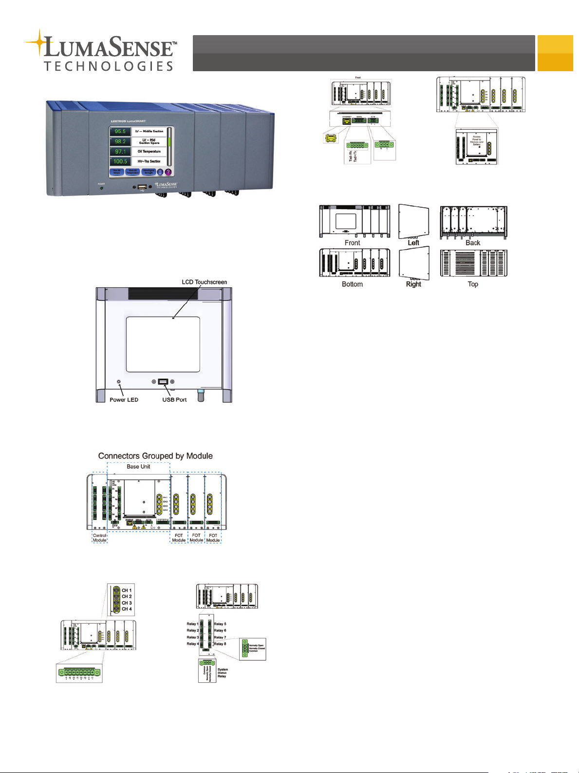
Controller Features (Front)
Additional Controller Images
LumaSMART Controller with FOT and Relay Modules Bottom View
(Front Facing Upwards)
LumaSMART Controller Base Unit
Communication and Power
Connections
(Front Facing Upwards)
LumaSMART Controller with Added FOT and Relay Modules
LumaSMART Controller Base
Unit Access Panel (Front Facing
Upwards)
Unpacking and Inspection
1) Upon receipt, inspect the container in which the
LumaSMART controller is packaged prior to opening
to ensure there is no obvious damage that may have
occurred during shipping.
If there is reason to suspect that the contents were
damaged in shipping, immediately file a claim with
the carrier before contacting LumaSense.
2) Open the shipping container and carefully remove
the LumaSMART controller and related instruments.
3) Check the contents against the enclosed packing list
and inspect for signs of visible damage.
If any items are missing or if there is visible damage
to the instruments, contact:
Customer Care (Santa Clara, CA)
Email: support@lumasenseinc.com
Phone: +1 800 631 0176 or +1 (408) 727-1600
4) If everything is in order, save the packing material for
possible future use.
Mounting the LumaSMART
LumaSMART Controller FOT
Connections (Front Facing
Upwards)
LumaSMART Controller Relay
Connections (Front Facing
Upwards)
Controller
The LumaSMART controller can be mounted using one of
three methods: wall, panel, or rack mount. Refer to
section 4.2 of the manual (a copy is available on the
enclosed CD) for mounting instructions.
Connecting Fiber Optic
Extensions
Connect one of the following to the instrument to
ensure that no light enters the unit as it will cause
erroneous readings: fiber optic extensions, phosphor
plugs, or (at a minimum) the black plastic endcaps that
came with the unit. See Section 4.3 of the manual for
details on installing fiber optic extensions. A fiber optic
Page 2
extension, a black cap or phosphor plug must be installed
in each of the active channels to avoid PE (Probe Error)
appearing. Ambient light will give erroneous readings if
the extensions connectors of the instrument are exposed
to it.
Installing Electrical Wiring
The table below outlines the standard configuration, as
well as the optional infrastructure communication.
Characteristic Specification
Analog Output 4 to 20 mA or 0 to 1 mA
Programmable
Relays
0, 8, or 16 Form-C
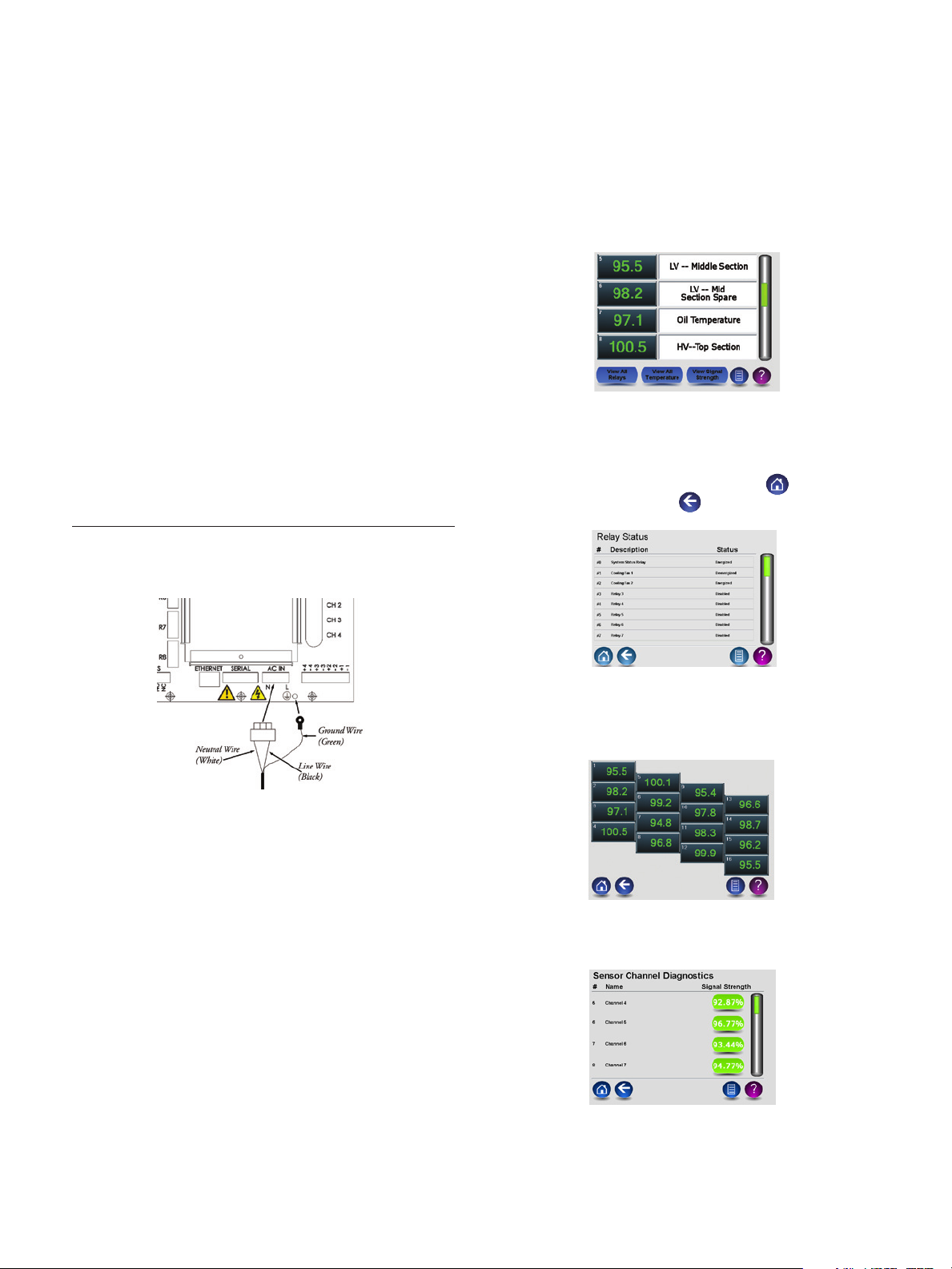
Channels (Home)
The Home screen displays a scrolling list of all the available probe channels. This view displays basic information about each channel, such as temperature (or P.E. for
probe error if a signal is not available) and channel name.
All temperatures are in Celsius. Channel statuses update
every 10 seconds.
Note: The default labels are Channel 1, 2, 3, and 4. To
change these default names, go to the setup menu and
type in the nomenclature for each channel.
System Status
Relay
Optional
(Infrastructure)
Communication
Protocols
The LumaSMART controller accepts nominal power of 90
to 264 VAC or 127 to 130 VDC, 47 to 63 Hz. The power
supply is internally short-circuit and overload protected.
No power cord is supplied with the LumaSMART system.
Connect an appropriate cable. The power cable must
be at least 20 AWG and UL 1061 (300V, 80C) approved.
Be sure to wire the ground to the system’s screw (shown
below).
1 Form-C
RS-485/RS-422, RS-232, Ethernet
IEC 61850, Modbus, DNP3 or ASCII
Viewing All Relays
The View All Relays screen contains a scrollable list of all
relays and their current status. A disabled status means
that the probe must be configured via the relay setup
menu. To return to the main menu, click . To return
to the previous screen, click .
Viewing All Temperatures
The View All Temperatures screen contains a condensed
list of all probes. P.E. is shown when probe is not
connected properly or broken.
The LumaSMART system requires a circuit breaker on
the power line that feeds it as a secondary line. This
circuit breaker is used to power the unit ON and OFF.
The LumaSMART system does not include any external
switches or circuit breakers. Consult local building codes
for the appropriate switch or circuit breaker to install.
Externally fuse for 200W.
See Sections 4.4.2, 4.4.3, and 4.4.4 of the technical
manual for analog output wiring, relay output wiring,
and optional communication wiring.
Starting up the Instrument
When powering up the instrument, let the instrument
run until the LumaSMART software is running.
Note: During the first minute of starting up, some relays
will be active. All relays should return to normally closed
once the software starts. During this time, please make
sure all of the fans and trips are turned off. After the
software starts, it is safe to turn the fans, trips, and
pumps on.
Viewing Signal Strength
The Sensor Channel Diagnostics screen contains a scrollable list of all channels and their current signal strength.
Warning: Ensure that all unused channels (channels with
no probes connected) have caps in place at all times. If an
unused channel is not capped, ambient light may affect
the temperature reading of other channels.
Page 3

Main Menu
The Main Menu contains buttons leading to all of
the main functions and configuration options of the
LumaSMART.
Administrator Setup
The Administrator Setup screen allows you to make
important updates to your software by changing the
authentication codes or applying a firmware upgrade. A
password is required to access this screen.
Download Firmware - Allows you to download updates.
Export Error Log - Allows you to export any errors.
Authentication Code - Allows you to change the code for
the setup menu and/or for the administrative setup menu.
Inventory Data - Allows you to view all manufacturing
test data and unit information.
Set Up
The Set Up Menu contains menus allowing you to
configure Transformer Information, Relay and Control,
Date and Time, Analog Outputs, Administrator Tools, and
Channel Setup.
Note: A password is required to access the Setup screen.
The default authentication code for entering the Setup
menu is 12345. It is strongly recommended that you
change your authentication code from the default to a
unique code for added security.
Note: When configuring options in the Set Up submenus,
be sure to press the Save button before exiting the
screen. To exit the screen without saving, press the
button.
Transformer Info Setup
The Transformer Info Setup screen allows you to input
the details of your transformer, including name, type and
year of manufacture.
Relay & Control
Allows you to configure settings for each relay, such as
the relay’s name, Alarm/Restore setpoints, Failsafe operation. Select the EDIT tab for the desired relay to change
its settings.
Relay Setup
The Relay Setup screen allows you to configure the
details of each relay. You can set the name, Energize configuration, association to probe(s), OR or AVG function,
and Alarm and Restore setpoints. Press the button
next to each entry to configure it.
1) Press the button next to each entry to bring up
a keyboard or number pad.
2) Type a new value and press Enter to apply it.
3) Press to save all entries.
Date & Time
The Date and Time screen allows you to set the date and
time. This should be done soon after installation to ensure
the correct date and time is included in the data logs.
Name - Allows you to give the relay a descriptive title.
Pressing Edit will bring up a keyboard where you can
enter an alphanumeric name.
Relay Configuration - Allows you to select whether the
relay is Disabled (default) or Normally Deenergized
(standard) or Normally Energized (failsafe).
Control Settings - Takes you to a screen where you can
configure the relay’s logical function and which channels
that function applies to.
Page 4

The “OR” logical function sets the system to alert when
any of the selected channels passes the Alarm set-point
temperature. The “AVG” logical function sets the system
to alert when the average temperature of the selected
channels passes the Alarm setpoint temperature.
Under Linked Channels, select the channels you would
like the logical function to apply to. Be sure to press the
Save button to apply your settings before leaving the
menu screen.
1) Press to change the channel name or enable or
disable a channel.
2) Press next to the channel name to bring up
a keyboard where you can enter an alphanumeric
channel name.
3) Press the circle above Enabled or Disabled to enable
or disable the channel. (Your selection will turn
green.)
4) Press before leaving the screen to save your
changes.
Display
The display screen allows you to configure channel scroll
speed, time until the backlight is dimmed, and the brightness level of the screen.
Alarm Setpoint - The temperature at which the relay
will change from the Normally De/Energized state to the
opposite state.
Restore Setpoint - The temperature at which the relay
will change from the present state back to its Normally
De/Energized state.
Analog Outputs
The Analog Outputs overview screen shows a list of the
channels and their current analog output configuration.
Press to the right of a channel to scale a channel
module’s temperature and current level. See section 5.2.1
for more details.
Channel Setup
The Channel Setup Overview screen allows you to
configure each channel’s name and status.
Transformer Info
The Transformer info page displays the details about
the transformer. This information can be obtained from
the transformer manufacturer and entered into the
LumaSMART via the Setup menu.
The same text that appears under Transformer Name will
also appear at the top of the Main Menu screen.
Diagnostics
The Diagnostic menu provides tools to test probe signal
strength, communications, protocols and relay configuration. It also provides a file viewer and the ability to erase
data logs.
Data
The Data screen allows you to export a range of data to a
USB thumbdrive.
To export data:
1) Select the date range of the data you would like to
retrieve by using the up/down arrows.
2) Insert your USB thumbdrive into the port located
below the touchscreen and press .
3) When export is complete, a message will appear on
the screen. Do not remove the thumbdrive until you
see the confirmation message.
Temperature data is stored once every minute. The latest
end date you can select is the current date (shown in the
top center of Main Menu screen).
LumaSense Technologies Temperature and Gas Sensing Solutions
LumaSense Technologies Temperature and Gas Sensing Solutions
Americas and Australia
Sales & Service
Santa Clara, CA
Ph: +1 800 631 0176
Fax: +1 408 727 1677
Europe, Middle East, Africa
Sales & Service
Frankfurt, Germany
Ph: +49 69 97373 0
Fax: +49 69 97373 167
info@lumasenseinc.com
the information in this publication at any time.
For complete instruction, view the operational manual
located on the enclosed CD.
India
Sales & Support Center
Mumbai, India
Ph: +91 22 67419203
Fax: +91 22 67419201
China
Sales & Support Center
Shanghai, China
Ph: +86 133 1182 7766
Fax: +86 21 5877 2383
www.lumasenseinc.com
©2012 LumaSense Technologies. All rights reserved.LumaSense Technologies, Inc., reserves the right to change
LumaSMART Quickstart-EN 514-0001-01 Rev. B 12/04/12
 Loading...