


 Loading...
Series 320
IGA 320/23-LO IMPAC Pyrometer
OPERATION MANUAL
Confidential Information
The material contained herein consists of information that is the property of LumaSense Technologies and intended solely for use by the purchaser of the equipment described in this manual. All specifications are subject to change without notice. Changes are made periodically to the information in this publication, and these changes will be incorporated in new editions.
LumaSense Technologies prohibits the duplication of any portion of this manual or the use thereof for any purpose other than the operation or maintenance of the equipment described in this manual, without the express written permission of LumaSense Technologies.
Copyright
© LumaSense Technologies 2013. All rights reserved.
Trademarks
IMPAC is a trademark of LumaSense Technologies.
All other trademarks are trademarks, registered trademarks, and/or service marks of their respective holders.
|
Service Centers |
LumaSense Technologies, Inc. |
LumaSense Technologies GmbH |
North America |
Other Than North America |
Sales & Service |
Sales & Support |
Santa Clara, CA, USA |
Frankfurt, Germany |
Ph: +1 800 631 0176 |
Ph: +49 (0) 69 97373 0 |
Ph: +1 408 727 1600 |
Fax: +49 (0) 69 97373 167 |
Fax: +1 408 727 1677 |
|
Global and Regional Centers
Our Headquarter |
Americas, Australia, & Other Asia |
Europe, Middle East, Africa |
LumaSense Technologies, Inc. |
LumaSense Technologies, Inc. |
LumaSense Technologies GmbH |
Santa Clara, CA, USA |
Santa Clara, CA, USA |
Frankfurt, Germany |
Ph: +1 800 631 0176 |
Ph: +1 800 631 0176 |
Ph: +49 (0) 69 97373 0 |
Fax: +1 408 727 1677 |
Fax: +1 408 727 1677 |
Fax: +49 (0) 69 97373 167 |
Brazil |
India |
China |
LumaSense, Vendas Brasil |
LumaSense Technologies, India |
LumaSense Technologies, China |
Campinas, Brasil |
Mumbai, India |
Shanghai, China |
Ph: +55 19 3367 6533 |
Ph: + 91 22 67419203 |
Ph: +86 133 1182 7766 |
Fax: +55 19 3367 6533 |
Fax: + 91 22 67419201 |
Fax: +86 21 5877 2383 |
E-mail info@lumasenseinc.com support@lumasenseinc.com eusupport@lumasenseinc.com supportdk@lumasenseinc.com
Website http://www.lumasenseinc.com
Part No 39003068-EN
Revision B
August 2013

Contents
1 |
General........................................................................................................................... |
|
5 |
|
|
1.1 |
Information about the user manual..................................................................... |
5 |
|
|
|
1.1.1 |
Legend................................................................................................................. |
5 |
|
|
1.1.2 |
Terminology ........................................................................................................ |
5 |
|
1.2 |
Safety..................................................................................................................... |
|
5 |
|
1.3 |
Limit of liability and warranty ............................................................................. |
5 |
|
|
1.4 |
Unpacking the Instrument .................................................................................... |
6 |
|
|
1.5 |
Service Request, Repair, or Support..................................................................... |
6 |
|
|
1.6 |
Shipments to LumaSense for Repair .................................................................... |
7 |
|
|
1.7 |
Disposal / decommissioning ................................................................................. |
7 |
|
2 |
Introduction................................................................................................................... |
9 |
||
|
2.1 |
Appropriate use..................................................................................................... |
9 |
|
|
2.2 |
Scope of delivery................................................................................................... |
9 |
|
|
2.3 |
System Overview................................................................................................... |
9 |
|
|
2.4 |
Physical User Interface ........................................................................................ |
10 |
|
|
2.5 |
Accessories (optional)......................................................................................... |
10 |
|
|
|
2.5.1 |
Mounting........................................................................................................... |
10 |
|
|
2.5.2 |
Air purge ........................................................................................................... |
10 |
|
|
2.5.3 |
Displays.............................................................................................................. |
10 |
|
2.6 |
Transport, packaging, storage............................................................................ |
11 |
|
3 |
Controls and Connections........................................................................................... |
13 |
||
|
3.1 |
Electrical Installation .......................................................................................... |
13 |
|
|
|
3.1.1 Pin assignment of the male socket on the back of the pyrometer................... |
13 |
|
|
3.2 |
Connecting the pyrometer to a PC ..................................................................... |
14 |
|
|
|
3.2.1 Connecting to RS485 interface / baudrate ........................................................ |
14 |
|
|
|
3.2.2 |
Wait time tw...................................................................................................... |
14 |
|
|
3.2.3 |
Connecting additional analyzing devices.......................................................... |
15 |
|
3.3 |
Mechanical Installation....................................................................................... |
15 |
|
|
|
3.3.1 |
Fiber optic.......................................................................................................... |
15 |
|
|
3.3.2 |
Optical head ...................................................................................................... |
16 |
|
3.4 |
LED targeting light.............................................................................................. |
16 |
|
|
3.5 |
Optical head......................................................................................................... |
16 |
|
|
|
3.5.1 Spot size data (measuring distance from the front of the lens)....................... |
17 |
|
3.5.2Adjusting the required measuring distance with optical head or , fixed
|
adjusted.......................................................................................................................... |
17 |
|
3.5.3 Adjusting the required measuring distance with optical head , focusable.... |
18 |
4 Settings / parameter descriptions .............................................................................. |
19 |
|
4.1 |
Factory settings................................................................................................... |
19 |
4.2 |
Basic range........................................................................................................... |
19 |
4.3 |
Material................................................................................................................ |
19 |
4.4 |
Temperature display in °C or °F .......................................................................... |
19 |
4.5 |
Emissivity .......................................................................................................... |
20 |
IGA 320/23-LO Operating Manual |
Contents iii |

|
4.6 |
Transmittance .................................................................................................... |
20 |
|
|
4.7 |
EmiAutoFind ........................................................................................................ |
20 |
|
|
4.8 |
Response time / exposure time (t90).................................................................. |
20 |
|
|
4.9 |
Clear time of the maximum / minimum value storage (tCL) ............................ |
21 |
|
|
|
4.9.1 |
max / min........................................................................................................... |
21 |
|
4.10 |
Analog output ..................................................................................................... |
22 |
|
|
4.11 |
LED targeting light.............................................................................................. |
22 |
|
|
4.12 |
Subrange.............................................................................................................. |
22 |
|
|
4.13 |
Ambient temperature compensation................................................................. |
22 |
|
|
4.14 |
Address ................................................................................................................ |
22 |
|
|
4.15 |
Limit switch (SP1)................................................................................................ |
23 |
|
|
4.16 |
Operating hours .................................................................................................. |
23 |
|
5 |
Software InfraWin....................................................................................................... |
25 |
||
|
5.1 |
Connecting the pyrometer to a PC ..................................................................... |
25 |
|
|
5.2 |
Installation........................................................................................................... |
25 |
|
|
5.3 |
Program start....................................................................................................... |
25 |
|
|
5.4 |
Basic settings....................................................................................................... |
26 |
|
|
|
5.4.1 |
Open/Save.......................................................................................................... |
26 |
|
|
5.4.2 |
1 measur…......................................................................................................... |
26 |
|
|
5.4.3 |
Print ................................................................................................................... |
26 |
|
|
5.4.4 |
Close .................................................................................................................. |
26 |
|
|
5.4.5 |
Test .................................................................................................................... |
26 |
|
5.5 |
Measurement online trend................................................................................. |
27 |
|
|
5.6 |
Listing (analyzing)............................................................................................... |
28 |
|
|
5.7 |
Output .TXT file (analyzing)................................................................................ |
28 |
|
|
5.8 |
Trend output (analyzing) .................................................................................... |
28 |
|
|
5.9 |
PC sampling rate (time interval between two measurements)........................ |
29 |
|
|
5.10 |
Spot size calculator ............................................................................................. |
29 |
|
|
5.11 |
Search I/O Module................................................................................................ |
29 |
|
6 |
Maintenance ................................................................................................................ |
31 |
||
|
6.1 |
Safety................................................................................................................... |
|
31 |
|
6.2 |
Service.................................................................................................................. |
|
31 |
7 |
Data format UPP (Universal Pyrometer Protocol)...................................................... |
33 |
||
8 |
Technical data.............................................................................................................. |
37 |
||
9 |
Reference numbers...................................................................................................... |
39 |
||
|
9.1 |
Reference numbers instrument.......................................................................... |
39 |
|
|
9.2 |
Reference numbers accessories.......................................................................... |
39 |
|
10 |
Troubleshooting .......................................................................................................... |
41 |
||
Index .................................................................................................................................. |
|
|
43 |
|
IGA 320/23-LO Operating Manual |
Contents iv |

1 General
1.1Information about the user manual
Congratulations on choosing this high quality and highly efficient IMPAC pyrometer.
This manual provides important information about the instrument and can be used as a work of reference for installing, operating, and maintaining your pyrometer. It is important that you carefully read the information contained in this manual and follow all safety procedures before you install or operate the instrument.
To avoid handling errors, keep this manual in a location where it will be readily accessible.
1.1.1Legend
Note: The note symbol indicates tips and useful information in this manual. All notes should be read to effectively operate the instrument.
Attention: This sign indicates special information which is necessary for a correct temperature measurement.
Warnings and Cautions: The general warnings and cautions symbol signifies the potential for bodily harm or damage to equipment.
MB Shortcut for Temperature range (in German: Messbereich)
1.1.2Terminology
The terminology used in this manual corresponds to the VDI- / VDE-directives 3511, Part 4.
1.2Safety
This manual provides important information on safely installing and operating the
IGA 320/23-LO pyrometer. Several sections of this manual provide safety warnings to avert danger. These safety warnings are specified with a warning symbol. You must read and understand the contents of this manual before operating the instrument even if you have used similar instruments or have already been trained by the manufacturer.
It is also important to continually pay attention to all labels and markings on the instrument and to keep the labels and markings in a permanent readable condition.
Warning: The pyrometer is only to be used as described in this manual. It is recommended that you only use accessories provided by the manufacturer.
1.3Limit of liability and warranty
All general information and notes for handling, maintenance, and cleaning of this instrument are offered according to the best of our knowledge and experience.
LumaSense Technologies is not liable for any damages that arise from the use of any examples or processes mentioned in this manual or in case the content of this document should be incomplete or incorrect. LumaSense Technologies reserves the right to revise this document and to make changes from time to time in the content hereof without obligation to notify any person or persons of such revisions or changes.
IGA 320/23-LO Operating Manual |
Contents 5 |

All instruments from LumaSense Technologies have a regionally effective warranty period. Please check our website at http://info.lumasenseinc.com/warranty for up-to-date warranty information. This warranty covers manufacturing defects and faults which arise during operation, only if they are the result of defects caused by LumaSense Technologies.
The Windows compatible software was thoroughly tested on a wide range of Windows operating systems and in several world languages. Nevertheless, there is always a possibility that a Windows or PC configuration or some other unforeseen condition exists that would cause the software not to run smoothly. The manufacturer assumes no responsibility or liability and will not guarantee the performance of the software. Liability regarding any direct or indirect damage caused by this software is excluded.
The warranty is VOID if the instrument is disassembled, tampered with, altered, or otherwise damaged without prior written consent from LumaSense Technologies; or if considered by LumaSense Technologies to be abused or used in abnormal conditions. There are no userserviceable components in the instrument.
1.4Unpacking the Instrument
Thoroughly inspect the instrument upon delivery to purchaser. Check all materials in the container against the enclosed packing list. LumaSense Technologies cannot be responsible for shortages against the packing list unless a claim is immediately filed with the carrier. Final claim and negotiations with the carrier must be completed by the customer.
Save all packing materials, including the carrier’s identification codes, until you have inspected the pyrometer and find that there is no obvious or hidden damage. Before shipment, the pyrometer was examined and has been tested. If you note any damage or suspect damage, immediately contact the carrier and LumaSense Technologies, Inc.
1.5Service Request, Repair, or Support
Contact LumaSense Technologies Technical Support in case of a malfunction or service request. Provide clearly stated details of the problem as well as the instrument model number and serial number. Upon receipt of this information, Technical Support will attempt to locate the fault and, if possible, solve the problem over the telephone.
If Technical Support concludes that the instrument must be returned to LumaSense Technologies for repair, they will issue a Return Material Authorization (RMA) number.
Return the instrument upon receipt of the RMA number, transportation prepaid. Clearly indicate the assigned RMA number on the shipping package exterior. Refer to Section 1.6, Shipments to LumaSense for Repair, for shipping instructions.
Technical Support can be contacted by telephone or email:
Santa Clara, California
Telephone: +1 408 727 1600 or +1 800 631 0176
Email: support@lumasenseinc.com
Frankfurt, Germany
Telephone: +49 (0) 69 97373 0
Email: eusupport@lumasenseinc.com
Erstein, France
Telephone +33 (0)3 88 98 98 01
Email supportdk@lumasenseinc.com
IGA 320/23-LO Operating Manual |
Contents 6 |

1.6Shipments to LumaSense for Repair
All RMA shipments of LumaSense Technologies instruments are to be prepaid and insured by way of United Parcel Service (UPS) or preferred choice. For overseas customers, ship units airfreight, priority one.
The instrument must be shipped in the original packing container or its equivalent. LumaSense Technologies is not responsible for freight damage to instruments that are improperly packed.
Contact us to obtain an RMA number (if one has not already been assigned by Technical Support). Clearly indicate the assigned RMA number on the shipping package exterior.
Send RMA Shipments to your nearest technical service center:
Customers in North America |
All other customers should |
should send RMA Shipments to: |
send RMA Shipments to: |
Santa Clara, California |
Frankfurt, Germany |
LumaSense Technologies, Inc. |
LumaSense Technologies GmbH |
3301 Leonard Court |
Kleyerstr. 90 |
Santa Clara, CA 95054 USA |
60326 Frankfurt |
Telephone: +1 408 727 1600 |
Germany |
+1 800 631 0176 |
Telephone: +49 (0)69-97373 0 |
Email: support@lumasenseinc.com |
Email: eusupport@lumasenseinc.com |
1.7Disposal / decommissioning
Inoperable IMPAC pyrometers must be disposed of in compliance with local regulations for electro or electronic material.
IGA 320/23-LO Operating Manual |
Contents 7 |

To ensure consistent document formatting, this page was intentionally left blank.
IGA 320/23-LO Operating Manual |
Contents 8 |

2 Introduction
2.1Appropriate use
The IGA 320/23-LO is a short wave infrared temperature measuring device with digital signal processing. It is used for non-contact temperature measurements on metals, ceramics, graphite, etc. with a temperature range between 100 and 1200 °C.
2.2Scope of delivery
Pyrometer IGA 320/23-LO, PC adjustment and evaluation software “InfraWin”, inspection sheet, manual. Fiber, one selectable optical head.
Note: A connection cable is not included with the instrument and has to be ordered separately (see Chapter 9, Reference numbers).
2.3System Overview
The IGA 320/23-LO is a short wavelength infrared measuring instrument with fiber optics and internal digital signal processing capabilities. This pyrometer is used for measurements of metallic surfaces, graphite and ceramics, etc.
For optimal match of the instrument to the application, two different optical heads are available. The small dimensions of the optics allow easy integration into compact production machines. The instrument is equipped with a fiber and an exchangeable optical head. The fiber and optical head are unaffected by electromagnetic interferences (e.g. induction) and can be used in high ambient temperatures up to 200 °C without additional cooling.
The LED targeting light enables precise alignment on the measurement object. It is automatically active and can be used during measurement. In addition to the analog output, the pyrometer is equipped with a digital RS485 interface, which enables secure data transmission to a PC or a PLC over long distances.
The included InfraWin software enables graphical display and storage of measurement values, as well as easy set-up of all instrument parameters.
IGA 320/23-LO Operating Manual |
Contents 9 |

2.4Physical User Interface
Robust stainless steel housing with small dimensions
|
Connection cable with |
|
|
connector and cables for: |
|
|
|
Power supply |
|
|
LED targeting light |
|
|
switch on/off |
Monofiber in |
|
RS485 interface |
Analog output |
||
stainless steel, flexible |
|
|
protection tube |
|
|
Switch contact |
|
|
|
|
|
|
|
|
|
|
|
|
|
|
Precision optics |
|
|
|
|
|
|
|
LED targeting light shows middle |
|
|
|
|
of spot size and optics focus |
|
|
|
|
|
|
|
|
2.5Accessories (optional)
Numerous accessories guarantee easy installation of the pyrometer. The following overview shows a selection of suitable accessories. You can find the entire accessory program with all reference numbers in Chapter 9, Reference numbers.
2.5.1 |
Mounting |
|
|
To mount and align the optical head to the |
|
||
measured object, mounting angles or a ball and |
|
||
socket mounting are available. Both options allow |
|
||
you to easily mount the optical head and align it to |
|
||
the measured object. However, the clamping-screws |
|
||
of the ball and socket mounting also allow you to |
|
||
quickly adjust the pyrometer in all directions. |
|
||
|
Mounting angles |
||
|
|
Ball and socket mounting |
|
2.5.2 |
Air purge |
|
|
The air purge protects the lens from contamination |
|
||
of dust and moisture. It has to be supplied with dry |
|
||
and oil-free pressurized air (1.5 m³ / h) and generates |
Air purge |
||
an air stream shaped like a cone. |
|||
|
|||
2.5.3 |
Displays |
|
|
For temperature indication, several digital displays |
|
||
are available. Some of them can also be used for |
|
||
remote configuration of the pyrometer. |
|
||
|
Digital display |
LED large display |
|
|
DA 6000 |
|
|
IGA 320/23-LO Operating Manual |
Contents 10 |
2.6Transport, packaging, storage
With faulty shipping, the instrument can be damaged or destroyed. To transport or store the instrument, please use the original box or a box padded with sufficient shock-absorbing material. For storage in humid areas or shipment overseas, the device should be placed in welded foil (ideally along with silica gel) to protect it from humidity.
The pyrometer is designed for a storage temperature of -20 to 70 °C with non-condensing conditions. Storing the insturment out of these conditions can cause damage or result in malfunction of the pyrometer.
IGA 320/23-LO Operating Manual |
Contents 11 |

To ensure consistent document formatting, this page was intentionally left blank.
IGA 320/23-LO Operating Manual |
Contents 12 |

3 Controls and Connections
3.1Electrical Installation
The IGA 320/23-LO is powered by a voltage of 24 V DC (possible range 10 to 30 V, ripple < 0.5 V). It is important to ensure correct polarity when connecting the device to the power supply.
To meet the electromagnetic requirements (EMV), a shielded connecting cable must be used. LumaSense offers connecting cables, which are not part of the standard scope of delivery. The shield of the connecting cable has to be connected only on the pyrometer’s side. If the connecting cable is extended, the shield of the extension also needs to be extended. The shield must be open on the power supply side (switch board), to avoid ground loops.
The connecting cable has wires for the power supply, interface, analog output, switch contact, and external clearing of the maximum value storage via contact and 8-pin connector (see Chapter 9, Reference numbers).
Warning: Follow common safety regulations for mains voltage (230 or 115 V AC) and connecting additional devices operating with this mains voltage (e.g. transformers). Touching mains voltage can be fatal. A non expert connection and mounting can cause serious health or material damages.
Only qualified specialists are allowed to connect such devices to the mains voltage.
Once the instrument has been connected to the power supply, it is immediately ready for use. Although it does not need to be warmed up, it does need to run for approximately 15 to 30 minutes before achieving full accuracy. The instrument can be switched off by interrupting the power supply or unplugging the electrical connector.
3.1.1Pin assignment of the male socket on the back of the pyrometer
Pin |
Color |
Indication |
|
1 |
white |
+ 24 V power supply |
|
2 |
brown |
0 V power supply |
|
3 |
green |
+ Iout analog output |
|
4 |
yellow |
– Iout analog output |
|
5 |
grey |
Switches on and off LED targeting light |
|
(via push button) (bridge to +24 V) |
|||
|
|
||
6 |
blue |
switch contact (reference point 0 V) |
|
7 |
violet |
A1 |
|
8 |
black |
B1 |
|
7 |
red/blue |
A2 (bridge to A1) |
|
8 |
gray/pink |
B2 (bridge to B1) |
|
|
orange |
Screen only for cable extension, |
|
|
don’t connect at the switchboard |
||
|
|
Male socket
4 |
5 |
6 |
Pin assignment |
|
|||
|
|
|
|
3 |
8 |
7 |
(side of male |
2 |
|
1 |
inserts) |
|
|
IGA 320/23-LO Operating Manual |
Controls and Connections 13 |
3.2Connecting the pyrometer to a PC
The pyrometer is equipped with an RS485 serial interface. With the RS485, long transmission distances can be realized and the transmission is, to a large extent, free of problems. The RS485 also allows several pyrometers to be connected in a bus system.
If an RS485 connection is not available at the PC, it can be accomplished using the RS485 to USB connector. When using a RS485 to USB adapter, make sure that the adapter is fast enough to receive the pyrometer’s answer to an instruction of the master. Most of the commonly used adapters are too slow for fast measuring equipment, so it is recommended to use the
RS485 USB converter “USB nano“ (ref. no. 3 852 600).
With a slow RS485 connection, it is also possible to set a wait time to the pyrometer (e.g. via the “Test” field of the software InfraWin, see Chapter 5 Software Infrawin) which delays the response of a command to the pyrometer (see also 3.2.2, Wait time tw).
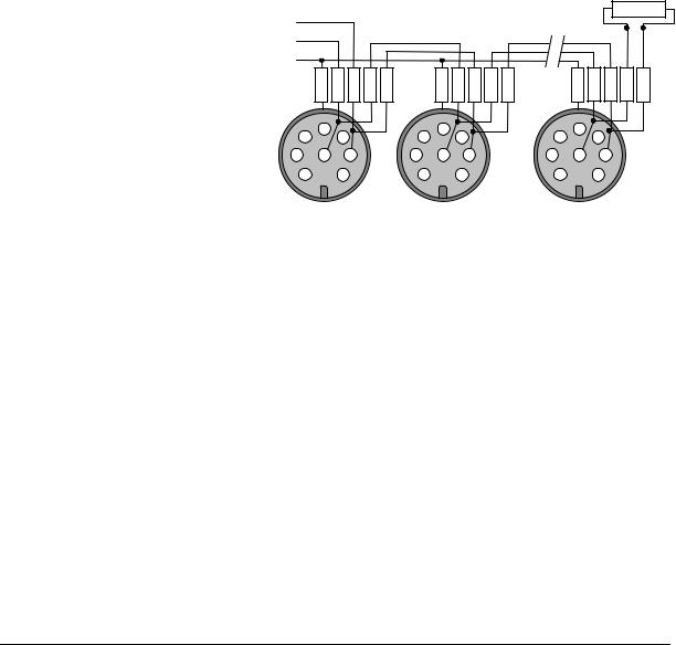
3.2.1Connecting to RS485 interface / baudrate
The pyrometer is operating in half-duplex mode. A1 and A2 as well as B1 and B2 are bridged in the 8-pin round connector of the connecting cable, to prevent reflections due to long stubs. It also safeguards against the interruption of the RS485 bus system, should a connecting plug be pulled out. The master labels mark the connections on the RS485 converter.
|
|
|
|
|
|
|
|
|
|
Terminator |
Master |
|
|
|
|
|
|
|
|
|
120 Ohm |
A |
|
|
|
|
|
|
|
|
|
|
B |
|
|
|
|
|
|
|
|
|
|
S |
GRND |
|
|
|
GRND |
|
|
|
GRND |
|
|
B2 A2 B1 A1 |
|
|
B2 A2 B1 A1 |
|
|
B2 A2 B1 A1 |
|||
4 |
5 |
6 |
|
4 |
5 |
6 |
|
4 |
5 |
6 |
|
|
|
|
|
||||||
3 |
8 |
7 |
3 |
|
8 |
7 |
3 |
|
8 |
7 |
2 |
|
1 |
|
2 |
|
1 |
|
2 |
|
1 |
The transmission rate of the |
Pyrometer 1 |
Pyrometer 2 |
Pyrometer 32 |
serial interface in Baud (Bd) is |
e.g. address 00 |
e.g. address 01 |
e.g. address 31 |
dependent on the length of |
|
|
|
the cable. Values between |
|
|
|
1200 and 38400 Bd may be set |
|
|
|
(via 5, software InfraWin or the command “br” when using another communication software, see command table under 7, data format UPP®). The baud rate is reduced by 50% when the transmission distance is doubled. The typical cable length for 19200 Bd is 2 km.
3.2.2Wait time tw
When using a pyrometer with RS485, it is possible that the connection is not fast enough to receive the pyrometer’s answer to an instruction of the master. In this case, a wait time (between 00 and 99 bit) can be set to slow down the data transfer (e.g.: tw = 02 at a baud rate 9600 means a wait time of 2/9600 sec).
IGA 320/23-LO Operating Manual |
Controls and Connections 14 |
Loading...