

Page 1
MANUAL
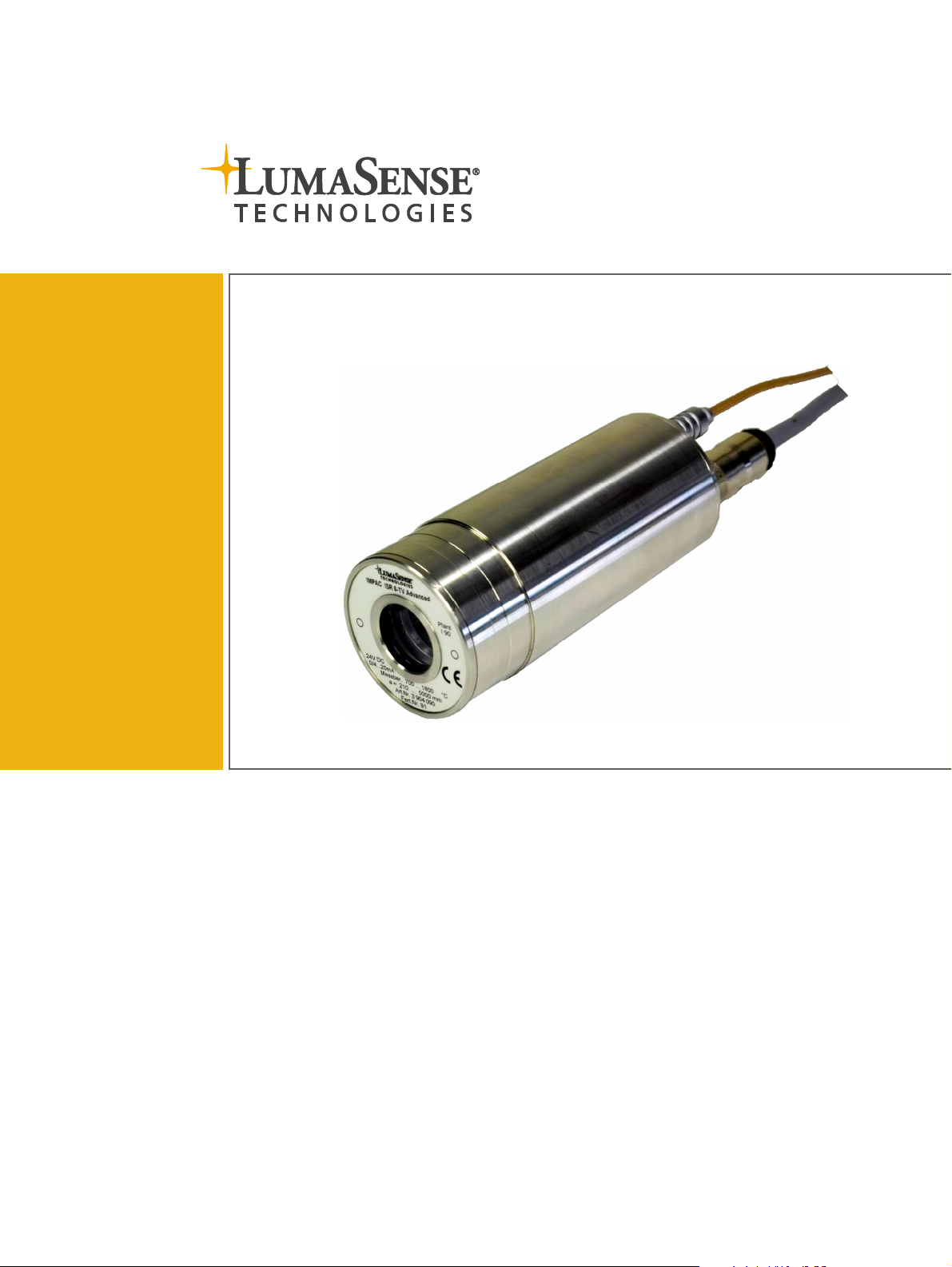
IMPAC Pyrometers
IS 6-TV Advanced · IGA 6-TV Advanced · ISR 6-TV Advanced
Addendum to IS 6 Advanced, IGA 6 Advanced, and ISR 6 Advanced Manuals
Page 2

Confidential Information
Service Centers
LumaSense Technologies, Inc.
LumaSense Technologies GmbH
Global and Regional Centers
Our Headquarter
s
Americas, Australia, & Other Asia
Europe, Middle East, Africa
Brazil
India
China
E-mail
info@lumasenseinc.com
support@lumasenseinc.com
Website
http://
www.lumasenseinc.com
The material contained herein consists of information that is the property of LumaSense
Technologies and intended solely for use by the purchaser of the equipment described in this
manual. All specifications are subject to change without notice. Changes are made periodically
to the information in this publication, and these changes will be incorporated in new editions.
LumaSense Technologies prohibits the duplication of any portion of this manual or the use
thereof for any purpose other than the operation or maintenance of the equipment described
in this manual, without the express written permission of LumaSense Technologies.
Copyright
© LumaSense Technologies 2013. All rights reserved.
Trademarks
IMPAC is a trademark of LumaSense Technologies.
All other trademarks are trademarks, registered trademarks, and/or service marks of their
respective holders.
North America
Sales & Service
Santa Clara, CA, USA
Ph: +1 800 631 0176
Ph: +1 408 727 1600
Fax: +1 408 727 1677
LumaSense Technologies, Inc.
Santa Clara, CA, USA
Ph: +1 800 631 0176
Fax: +1 408 727 1677
LumaSense, Vendas Brasil
Campinas, Brasil
Ph: +55 19 3367 6533
Fax: +55 19 3367 6533
eusupport@lumasenseinc.com
supportdk@lumasenseinc.com
Other Than North America
Sales & Support
Frankfurt, Germany
Ph: +49 (0) 69 97373 0
Fax: +49 (0) 69 97373 167
LumaSense Technologies, Inc.
Santa Clara, CA, USA
Ph: +1 800 631 0176
Fax: +1 408 727 1677
LumaSense Technologies, India
Mumbai, India
Ph: + 91 22 67419203
Fax: + 91 22 67419201
LumaSense Technologies GmbH
Frankfurt, Germany
Ph: +49 (0) 69 97373 0
Fax: +49 (0) 69 97373 167
LumaSense Technologies, China
Shanghai, China
Ph: +86 133 1182 7766
Fax: +86 21 5877 2383
Part No 03 904 212 - EN
Revision B
November 2013
Page 3

Contents
1 General Information ...................................................................................................... 5
1.1 Information about the user manual ..................................................................... 5
1.1.1 Legend ................................................................................................................. 5
1.1.2 Terminology ........................................................................................................ 5
1.2 Safety ..................................................................................................................... 5
1.3 Limit of liability and warranty ............................................................................. 5
1.4 Unpacking the Instrument .................................................................................... 6
1.5 Transport, Packing, Storage .................................................................................. 6
1.6 Service Request, Repair, or Support ..................................................................... 6
1.7 Shipments to LumaSense for Repair .................................................................... 7
1.8 Disposal / decommissioning ................................................................................. 7
2 Introduction ................................................................................................................... 9
2.1 Technical Data ....................................................................................................... 9
2.2 Dimensions .......................................................................................................... 10
3 Electrical Installation................................................................................................... 11
3.1 Video Output Electrical Connection ................................................................... 11
3.1.1 Video Image ...................................................................................................... 11
4 Software InfraWin ....................................................................................................... 13
4.1 Set Video Mode Parameters ............................................................................... 13
4.2 Adjusting Brightness ........................................................................................... 13
5 Accessory (optional) .................................................................................................... 17
5.1 Video Grabber (Converts Analog TV to USB) ..................................................... 17
5.1.1 Adjusting Grabber Settings ............................................................................... 17
5.1.2 Adjusting Video Output Settings ...................................................................... 18
5.1.3 Viewing the Video Image .................................................................................. 18
6 Data format Universal Pyrometer Protocol (UPP): Extended for Video Module ...... 19
7 Reference Numbers ..................................................................................................... 23
7.1 Reference numbers instrument .......................................................................... 23
7.2 Reference numbers accessories (video related) ................................................ 23
7.3 Reference numbers accessories (other) ............................................................. 23
Index .................................................................................................................................. 25
Series 6 – TV Advanced Manual Contents · iii
Page 4

To ensure consistent document formatting, this page was intentionally left blank.
Series 6 – TV Advanced Manual Contents · iv
Page 5
1 General Information
1.1 Information about the user manual
Congratulations on choosing the high quality and highly efficient IMPAC Series 6-TV Advanced
pyrometer. This manual provides important information about the instrument and can be used
as a work of reference for installing, operating, and maintaining your Series 6-TV Advanced
pyrometer. It is important that you carefully read the information contained in this manual and
follow all safety procedures before you install or operate the instrument. To avoid handling
errors, keep this manual in a location where it will be readily accessible.
Note: This user manual is intended to supplement the Series 6 Advanced pyrometer
manual for the TV version. Additional information about the pyrometer can be found
in the corresponding IS 6 Advanced / IGA 6 Advanced / ISR 6 Advanced manual.
1.1.1 Legend
Note: The note symbol indicates tips and useful information in this manual. All notes
should be read to effectively operate the instrument.
Warnings and Cautions: The general warnings and cautions symbol signifies the
potential for bodily harm or damage to equipment.
MB Shortcut for Temperature range (in German: Messbereich)
1.1.2 Terminology
The terminology used in this manual corresponds to the VDI- / VDE-directives 3511, Part 4.
1.2 Safety
This manual provides important information on safely installing and operating the
Series 6-TV Advanced pyrometer. Several sections of this manual provide safety warnings to
avert danger. These safety warnings are specified with a warning symbol. You must read and
understand the contents of this manual before operating the instrument even if you have used
similar instruments or have already been trained by the manufacturer.
It is also important to continually pay attention to all labels and markings on the instrument and
to keep the labels and markings in a permanent readable condition.
Warning: The pyrometer is only to be used as described in this manual. It is
recommended that you only use accessories provided by the manufacturer.
1.3 Limit of liability and warranty
All general information and notes for handling, maintenance and cleaning of this instrument
are offered according to the best of our knowledge and experience.
All IMPAC Series 6-TV pyrometers from LumaSense Technologies have a regionally effective
warranty period. Please check our website at http://info.lumasenseinc.com/warranty for up-todate warranty information. This warranty covers manufacturing defects and faults which arise
during operation, only if they are the result of defects caused by LumaSense Technologies.
Series 6 – TV Advanced Manual General Information · 5
Page 6

The warranty is VOID if the instrument is disassembled, tampered with, altered, or otherwise
damaged without prior written consent from LumaSense Technologies; or if considered by
LumaSense Technologies to be abused or used in abnormal conditions.
The Windows compatible software was thoroughly tested on a wide range of Windows
operating systems and in several world languages. Nevertheless, there is always a possibility that
a Windows or PC configuration or some other unforeseen condition exists that would cause the
software not to run smoothly. The manufacturer assumes no responsibility or liability and will
not guarantee the performance of the software. Liability regarding any direct or indirect
damage caused by this software is excluded.
There are no user-serviceable components in the instrument. The warranty is VOID if the
instrument is disassembled, tampered with, altered, or otherwise damaged without prior
written consent from LumaSense Technologies; or if considered by LumaSense Technologies to
be abused or used in abnormal conditions.
1.4 Unpacking the Instrument
Before shipment, each instrument is assembled, calibrated, and tested at the LumaSense Factory.
When unpacking and inspecting your system components, you need to do the following:
1. Check all materials in the container against the enclosed packing list.
LumaSense Technologies cannot be responsible for shortages against the packing list
unless a claim is immediately filed with the carrier. Final claim and negotiations with the
carrier must be completed by the customer.
2. Carefully unpack and inspect all components for visible damage. If you note any damage
or suspect damage, immediately contact the carrier and LumaSense Technologies, Inc.
3. Save all packing materials, including the carrier’s identification codes, until you have
inspected all components and find that there is no obvious or hidden damage.
Note: LumaSense encourages you to register your product with us to receive updates,
product information, and special service offers:
http://info.lumasenseinc.com/registration.
1.5 Transport, Packing, Storage
With faulty shipping, the instrument can be damaged or destroyed. To transport or store the
instrument, please use the original box or a box padded with sufficient shock-absorbing
material. For storage in humid areas or shipment overseas, the device should be placed in
welded foil (ideally along with silica gel) to protect it from humidity.
The pyrometer is designed for a storage temperature of -20 to 80 °C with non-condensing
conditions. Storing the instrument out of these conditions can cause damage or result in
malfunction of the pyrometer.
1.6 Service Request, Repair, or Support
Contact LumaSense Technologies Technical Support in case of a malfunction or service request.
Provide clearly stated details of the problem as well as the instrument model number and serial
number. Upon receipt of this information, Technical Support will attempt to locate the fault
and, if possible, solve the problem over the telephone.
If Technical Support concludes that the instrument must be returned to LumaSense Technologies
for repair, they will issue a Return Material Authorization (RMA) number.
Series 6 – TV Advanced Manual General Information · 6
Page 7

Return the instrument upon receipt of the RMA number, transportation prepaid. Clearly
indicate the assigned RMA number on the shipping package exterior. Refer to Section 1.6,
Shipments to LumaSense for Repair, for shipping instructions.
Technical Support can be contacted by telephone or email:
Santa Clara, California Frankfurt, Germany
Telephone:
+1 408 727 1600
+1 800 631 0176
Email:
support@lumasenseinc.com
Telephone:
+49 (0)69-97373 0
Email:
eusupport@lumasenseinc.com
Erstein, France
Telephone:
+33 (0)3 88 98 98 01
Email:
eusupport@lumasenseinc.com
1.7 Shipments to LumaSense for Repair
All RMA shipments of LumaSense Technologies instruments are to be prepaid and insured by
way of United Parcel Service (UPS) or preferred choice. For overseas customers, ship units airfreight, priority one.
The instrument must be shipped in the original packing container or its equivalent. LumaSense
Technologies is not responsible for freight damage to instruments that are improperly packed.
Contact us to obtain an RMA number (if one has not already been assigned by Technical
Support). Clearly indicate the assigned RMA number on the shipping package exterior.
Send RMA Shipments to your nearest technical service center:
Santa Clara, California Frankfurt, Germany
LumaSense Technologies, Inc.
3301 Leonard Court
Santa Clara, CA 95054 USA
Telephone: +1 408 727 1600
+1 800 631 0176
LumaSense Technologies GmbH
Kleyerstr. 90
60326 Frankfurt
Germany
Telephone: +49 (0)69-97373 0
Email: support@lumasenseinc.com
Email: eusupport@lumasenseinc.com
1.8 Disposal / decommissioning
Inoperable IMPAC pyrometers must be disposed of in compliance with local regulations for
electro or electronic material.
Series 6 - TV Advanced Manual General Information · 7
Page 8

To ensure consistent document formatting, this page was intentionally left blank.
Series 6 - TV Advanced Manual General Information · 8
Page 9

2 Introduction
FBAS
-
Signal ca. 1 VSS at 75 Ohms,
Date/Time:
Real time clock with about 14 days buffer (GoldCap)
Connection of Video
-
Signal:
Separate triaxial socket to support double shielded signal
Operating ambient
0 to 60
°C on the housing
Field of view:
ca. 5.8% x 4.2% of the adjusted measuring distance
Resolution
:
768 x 576 Pixel video chip
Brightness control
:
Automatic or manual (via software)
Note
2.1 Technical Data
(Different from IS 6 Advanced / IGA 6 Advanced / ISR 6 Advanced)
Video-Signal:
PAL (B), 50 Hz, CCIR656
video output galvanically isolated from power supply, analog
output and digital interface
transmission (at pyrometer)
BNC connector (on user side - BNC-RCA adapter included)
Video signal can be switched off via software
temperature:
Note: During operation the
instruments will warm up and might
reach an intrinsic temperature of up
to 58 °C
Optics
Superimposed text elements: Circular target marker, user text, time, date, measured
temperature
Additional: device temperature or distance or serial nr. or
intensity (only ISR)
768 x 520 Pixel displayed on screen
: The calibration / adjustment of this pyrometer is carried out in accordance with
VDI/VDE 3511, Part 4.4. See http://info.lumasenseinc.com/calibration for more
information.
Series 6 – TV Advanced Manual Electrical Installation · 9
Page 10

2.2 Dimensions
All dimensions in mm
Series 6 – TV Advanced Manual Electrical Installation · 10
Page 11

3 Electrical Installation
Triaxial video
-
output
Focus adjustment set screw
12-pin connector
4 digit LED display
3.1 Video Output Electrical Connection
On the back cover of Series 6-TV Advanced pyrometers, there is an additional coaxial connector
for the video output. LumaSense offers ready-made video connection cables in various lengths,
which are fitted with a BNC connector and a BNC-RCA adapter to connect to a monitor or video
grabber.
Rear View of the Pyrometer
3.1.1 Video Image
The video image is used for aligning the pyrometer to the measuring object and shows the
following information:
· The measuring object and its surroundings
· Target marking circle (The size of the circle corresponds to the measuring target size)
· Current temperature reading
· In addition to the measuring temperature, one of the following parameters is displayed:
o Internal temperature of the pyrometer (Tcase)
o Measuring distance (a = xxxxx)
o Serial number (SNo: xxxx)
o Signal intensity (I = xxx.x% only ISR 6)
· Current Time and Date
· User text (e.g. "LumaSense")
Series 6 – TV Advanced Manual Electrical Installation · 11
Example of a video image
Page 12

Operating Mode
The two dots above the letter “T” show
the selected operating mode
(ISR 6-TV Advanced only).
· 2-channel mode: 2 dots
displayed. If the signal falls
below the set Relative Signal
(see "Relative Signal" in
ISR 6 Advanced Manual), the
temperature displayed on the
image will be flashing.
· 1-channel mode: only the left
dot is displayed.
· Metal mode: the left dot is
displayed continuously,
the right dot flashes.
Series 6 – TV Advanced Manual Electrical Installation · 12
Page 13

4 Software InfraWin
Using a PC and the InfraWin 5 software (included in scope of delivery), the video image and
display options can be configured.
4.1 Set Video Mode Parameters
1. Choose TV for setting the parameters of the video module.
2. Complete the following fields on the screen:
· Text: Enter user text (e.g "LumaSense")
· Parameters: Display in addition to measuring temperature
o Off (no parameter is displayed)
o Device temperature
o Measuring distance
o Serial number
o Signal intensity (ISR 6 only)
· Brightness: Selects the brightness adjustment mode of the video image:
automatic or manual
· Video Output: To turn on/off the video output (high impedance=off)
· Date and Time Settings: Set the current time and date
3. Click the Accept button to save the settings.
4.2 Adjusting Brightness
You can set the brightness control to Manual (Man.) or Automatic (Auto) using the InfraWin 5
software.
Series 6 – TV Advanced Manual Software Infrawin · 13
Page 14

· Manual - the brightness of the video image can be set manually using the slider at the
right side of the video image.
· Automatic - the brightness of the video image is automatically controlled. Using the
two sliders (red and blue) at the right side of the video image, a range of brightness can
be set where the automatic control should work. With the yellow button, the selected
range can be moved.
If the circle (representing the current brightness) is within the chosen range, automatic
brightness control is not active. Once the circle is outside of the chosen range, automatic
brightness control activates and automattically adjusts the brightness until the circle returns to
the chosen range.
These settings affect the video chip in the pyrometer. By pressing the Accept button, the
settings are stored in the pyrometer.
Series 6 – TV Advanced Manual Software Infrawin · 14
Page 15

Comparison between manual and automatic control of brightness:
The measuring temperature was changed for the image recording from the beginning of the
measuring range to 1200 °C.
Manual brightness control Automatic brightness control
Series 6 – TV Advanced Manual Software Infrawin · 15
Page 16

To ensure consistent document formatting, this page was intentionally left blank.
Series 6 – TV Advanced Manual Software Infrawin · 16
Page 17

5 Accessory (optional)
5.1 Video Grabber (Converts Analog TV to USB)
Using the video grabber (optional accessory) in conjunction
with the software InfraWin 5, it is possible to see the video
image on the PC screen together with the temperature graph.
The video image can be size adjusted and positioned at any
place of the screen. The properties of the pyro's video chip as
well as properties of the video grabber can be adjusted with
InfraWin 5.
5.1.1 Adjusting Grabber Settings
On top of the video image there is a menu labeled Grabber settings. Set the properties of the
video image by changing the parameters of the video grabber (works like the controlling knobs
of a monitor).
1. Select Grabber settings.
2. Configure the desired settings.
3. Save the configured settings by pressing OK.
Series 6 – TV Advanced Manual Accessory (optional) · 17
Page 18

5.1.2 Adjusting Video Output Settings
1. Select Grabber input.
2. Currently, only “PAL_B” is supported.
5.1.3 Viewing the Video Image
During a temperature measurement of the pyrometer, the video image can be displayed on the
screen by pressing the TV button.
The video image can be positioned anywhere on the screen. Use the slider to change the
brightness of the image during the measurement.
Series 6 – TV Advanced Manual Accessory (optional) · 18
Page 19

6 Data format Universal Pyrometer
Protocol (UPP): Extended for Video
Module
Software commands can be exchanged directly with the pyrometer through an interface using
suitable communication software or by using the Test function located in the Pyrometer
Parameters window of the InfraWin software package.
The data exchange occurs in ASCII format with the following transmission parameters:
• The data format is: 8 data bits, 1 stop bit, even parity (8,1,e) no handshake;
• The device responds to the entry of a command with output (such as the measuring
value) + CR (Carriage Return, ASCII 13), to pure entry commands with ok + CR, or no +
CR.
• Every command starts with the 2-digit device address AA (e. g. "00"). This is followed by
1 lower case command letter and 2 numbers finished with CR.
Example Read Command: Entry: “00v08“ + <CR>
Selectable parameter that is additionally shown to the measuring temperature
Read selection: Answer: 2-digit, hex
e.g. "02" + <CR> The measured distance is displayed in addition to temperature.
o The ASCII parameter “X” indicates a change to be made in a parameter. When used, the
command contains the new value.
Example Write Command: Entry: “00v08XX “ + CR
The case temperature is additionally shown to the measuring temperature. A „?“
after the read command answers with the limits of the respective settings (only a
setting command, not a query command).
o A “?” after the lower case command letters answers with the limits of the respective
settings (only at setting commands, not at query commands).
Example Read Limits Command: Entry: “00v08?“ + CR!
The answer is "00FF" + <CR>
Series 6 – TV Advanced Manual Data format UPP · 19
Page 20

Description
Command
Parameters
v00
v00XX
Text fade in, set value. XX=00..1F,hex
Bit[0]: Overlay_0 -> parameter display
v01
v01
Pixel Coordinates of top left corner of temperature display read.
v01XXXYYY
Set Coordinates of temperature display.
v01?
Coordinates of
temperature display read limits.
v02
description see „v01“ but Coordinates of time/Date (Overlay_1)
v03
description see „v01“ but Coordinat
es of UserText (Overlay_2)
v05
v05
store v01,v02,v03,v04 in flash memory
v06
v06
UserText read. Answer: ASCII
-
String
v06nnS
UserText write.
v06?
UserText read limit. Answer
: 0132xy
v07
v07
Store user
-
text in flash memory
v08
v08
Selectable parameter, selection read.
v08XX
Selectable parameter, selection write. XX={00,01,80}
v08?
Selectable parameter, read limits.
v09
v09
Selectable parameter, store selection in flash memory
(0: fade out; 1: fade in)
Bit[1]: Overlay_1 -> Time/Date
(0: fade out; 1: fade in)
Bit[2]: Overlay_2 -> User-Text
(0: fade out; 1: fade in)
Bit[3]: Overlay_3 -> target circle
(0: fade out; 1: fade in)
Bit[4]: Firmware-Block Overlay-activation
(0: Off àall ovl’s off, resolution=768x576;
1: On àovl’s corresponding to Bit[3:0]
Settings on and resolution=768x520)
(Overlay_0)
Answer = XXXYYY (6-digit, hex)
XXX: X-Coordinate
YYY: Y-Coordinate (000 = top)
XXX: 000..300hex (X-Coordinate)
YYY: 000..208hex (Y-CoordinateàChange only in multiples of 2)
Answer: 000300000208 (PAL)
Format xxxXXXyyyYYY
xxx min X-Value, XXX max X-Value
yyy min Y-Value, YYY max Y-Value
nn: 01..32hex (number of characters)
S: ASCII-String (nn characters long)
x: first character is blank (0x20)
y: last character is ‘ÿ‘ (0xff)
Answer: 2-digit, hex
00: case temperature
02: measuring distance
03: Ser-No
80: Intensity (ISR 6 only);
FF: no parameter
Answer: 00FF
Series 6 – TV Advanced Manual Data format UPP · 20
Page 21

Description
Command
Parameters
v10
v10
Text properties parameter, read.
Answer 4-digit, hex.
v10ABCD
Text properties parameter, write.
v10?
Text-properti
es parameter, read limits.
v11
v11
Text properties (date/time)
v12
v12
Text properties (User Text)
v13
v13
reserved (Overlay_3 used for pictures
Lumas
enseLogo, circle marker,
v14
v14
store v10,v11,v12,v13 text properties in flash memory
v18
v18
Brightness control, settings read.
v18X
Brightness co
ntrol, settings write. X=0..1
v18?
Brightness control, read limits. Answer: 01
v19
v19
Brightness, read. Answer: 3
-
digit, hex.
v19XXX
Brightness, write. XXX=000..1A5
v19?
Brightness, r
ead limits. Answer: 0001A5
v20
v20
Brightness, store in flash memory.
v21
v21
AVG-Rectangle, properties read.
v21
AVG-Rectangle, properties write.
v21?
AVG-Rectangle, read
limits.
v22
v22
AVG-Rectangle, set to position and size of circle marker.
v23
v23
AVG-Rectangle, store in flash memory.
A: text color (0..F)
B: text transparency
(0..7 à 0: transparent; 7: full opacity)
C: background color (0..F)
D: background transparency (0..7)
Color palette:
0=black; 1=DarkRed; 2=Red; 3=Pink; 4=Teal; 5=Green; 6=BrightGreen;
7=Turquoise; 8=DarkBlue; 9=Violet; A=Blue; B=Grey 25%; C=Grey 50%;
D=DarkYellow; E=Yellow; F=White
In cross faded colorsàreduce opacity!!!
(e.g. Yellow)
Answer: 0F070F07
v11ABCD
v11?
v12ABCD
v12?
v13ABCD
v13?
AAABBBCCCDDD
description see „v10“
description see „v10
à
AVG_rectangle)
description see „v10“ however Text properties (Overlay_3)
Answer: 1-digit, hex.
0: manual brightness control
1: automatic brightness control
Answer: AAABBBCCCDDD (12-digit, hex)
AAA: width (004..300hex)
BBB: high (008..208hex à Change only in multiples of 2)
CCC: X-Coordinate (000..2FChex)
DDD: Y-Coordinate (000..200hex à Change only in multiples of 2)
· Coordinates-reference : corner top left
· If AAA+CCC > 768 , Answer „no“
· if BBB+DDD > 520 , Answer „no“
Series 6 – TV Advanced Manual Data format UPP · 21
Answer: 0043000082080002FC000200
Page 22

Description
Command
Parameters
v24
v24
Control limit, for automatic brightness read.
Answer: XXYY (4-digit, hex)
v24
XXYY
Control limit, for automatic brightness write.
v24?
Control limit, read limits. Answer: 00FF00FF
v25
v25
Control limit, store selection in flash memory
v26
v26
Time, read. Answer 6
-
digit, decimal
v26hhmmss
Time, write.
v26?Time, read limit. Answer: 002300590059
v27
v27
Date, read. Answer 6
-
digit, decimal
v27
DDMMYY
Date, write.
v27?Date, read limits. Answer: 013101120
099
v31
v31
Video
-
Out-Tristate read.
v31xVideo
-
Out-Tristate write. x = 0..1
v31?Video
-
Out-Tristate, read limits
v32
v32
Video
-
Out-Tristate, store selection in flash memory
XX: bottom Control limit (00..FFhex)
YY: top Control limit (00..FFhex)
brightness of the image is changed by the OV7960 till the average value of
the brightness, all pixels within the defined AVG rectangle, is in these
control limits)
hh: hour (00..23)
mm: minute (00..59)
ss: second (00..59)
DD: day (01..31)
MM: month (01..12)
YY: year (00..99)
Answer 1-digit, hex.
0: Disable
1: Enable
Answer: 01
Series 6 – TV Advanced Manual Data format UPP · 22
Page 23

7 Reference Numbers
IS 6-TV Advanced
600 to 1800 °C (MB 18)
3 914 570
600 to 3000 °C (MB 30
)
3 914 53
0
IGA 6
-
TV Advanced
250 to 1800 °C (MB 18
)
3 91
4 070250 to 2500 °C (MB 25)
3 914 030
ISR 6
-
TV Advanced
600 to 1400 °C (MB 14)
3 904 030
700 to 1800 °C (MB 18)
3 904 090
800 to 2500 °C (MB 25)
3 904 160
1000 to 3000 °C (MB 30)
3 904 230
7.1 Reference numbers instrument
Type Temperature Range Reference Number
(PAL / RS485)
(PAL / RS485)
(PAL / RS485)
Ordering note: Connection and video cables are not included in scope of delivery and must be
ordered separately.
7.2 Reference numbers accessories (video related)
3 920 600
3 920 610
3 920 620
3 920 630
3 920 640
3 920 650
3 920 660
3 920 670
3 920 680
3 920 690
3 826 740 Passive Video Baluns with BNC connectors for transmitting video signals over
3 826 730 Video grabber (converts analog TV to USB)
Video cable BNC, 5 m long
Video cable BNC, 10 m long
Video cable BNC, 15 m long
Video cable BNC, 20 m long
Video cable BNC, 25 m long
Video cable BNC, 30 m long
Video cable BNC, 40 m long
Video cable BNC, 45 m long
Video cable BNC, 60 m long
Video cable BNC, 100 m long
standard inexpensive patch cable (eg CAT5 cable). Maximum cable length:
300 m with color video.
All video cables include an
adapter BNC-socket to RCA
male (CINCH)
7.3 Reference numbers accessories (other)
3 820 320 Special connection cable with angled connector and additional targeting light
push button, 5 m long
3 820 330
3 820 500
3 820 510
3 820 810
3 820 820
3 820 520
3 820 340
3 820 530
3 820 540
3 820 830
5m connection cable with straight connector
10m connection cable with straight connector
15m connection cable with straight connector
20m connection cable with straight connector
25m connection cable with straight connector
30m connection cable with straight connector
5m connection cable with right angle connector
10m connection cable with right angle connector
15m connection cable with right angle connector
20m connection cable with right angle connector
(All connection cables include a
short adapter cable with a 9-pin
D-SUB connector. This
connector may be used in
combination with the RS485 to
USB adapter.)
Series 6 – TV Advanced Manual Reference Numbers · 23
Page 24

3
820 840
3 820 550
25m connection cable with ri
ght angle connector
30m connection cable with right angle connector
3 826 510 PI 6000: PID programmable controller, very fast, for digital IMPAC pyrometers
3 826 720 USB to RS485 adapter cable, 1.8 m long
3 834 210 Mounting support (adjustable)
3 835 160 Air purge unit, aluminum
3 835 590 90° mirror for Series 5 and Series 6, quartz glass window
3 837 530 Water cooling jacket (heavy duty) with integrated air purge for Series 6 with
video
3 846 260 Mounting support
3 846 290 Mounting support with fused silica window
3 846 590 Vacuum support KF16 with quartz glass window
3 852 290
3 852 550
Power supply NG DC for DIN rail mounting; 100 to 240 V AC Þ 24 V DC, 1 A
Power supply NG 2D for DIN rail mounting; 85 to 265 V AC Þ 24 V DC, 600 mA
with two settable limit switches
3 890 640 DA 4000-N: LED-digital display to be built into the switchboard
3 890 650 DA 4000: like DA 4000-N, but additionally with 2 limit switches
3 890 570 DA 6000-N digital display to allow adjustment of the Pyrometer through the
RS485 interface
3 890 530 DA 6000: like DA 6000-N with analog input and 2 limit switches for the RS485
interface
3 890 630 LD24-UTP; large digital indicator, 57 mm height of digits
Series 6 – TV Advanced Manual Reference Numbers · 24
Page 25

Index
A
Accessories 17
B
T
Technical Data 9
Transport 6
Brightness control 9, 13
D
Data format UPPÒ 19
Dimensions 10
Disposal 7
G
General Information 5
Grabber settings 17
L
Legend 5
Liability 5
O
operating mode 12
P
Packing 6
U
Unpacking the Instrument 6
UPPÒ data format 19
V
Video Grabber 17
Video Image 11
Video Mode Parameters 13
Video Output Electrical Connection 11
W
Warranty 5
R
Reference numbers
Accessories 23
Instrument 23
Reference Numbers 23
Repair 6, 7
Resolution 9
S
Safety 5
Service Request 6
Software InfraWin 13
Storage 6
Support 6
Series 6 – TV Advanced Manual Index · 25
 Loading...