

Page 1
MANUAL
IMPAC Pyrometers
ISR 6 Advanced
Page 2

Confidential Information
Service Centers
LumaSense Technologies, Inc.
LumaSense Technologies GmbH
Global and Regional Centers
Our Headquarter
s
Americas, Australia, & Other Asia
Europe, Middle East, Africa
Brazil
India
China
E-mail
info@lumasenseinc.com
support@lumasenseinc.com
Website
http://w
ww.lumasenseinc.com
The material contained herein consists of information that is the property of LumaSense
Technologies and intended solely for use by the purchaser of the equipment described in this
manual. All specifications are subject to change without notice. Changes are made periodically
to the information in this publication, and these changes will be incorporated in new editions.
LumaSense Technologies prohibits the duplication of any portion of this manual or the use
thereof for any purpose other than the operation or maintenance of the equipment described
in this manual, without the express written permission of LumaSense Technologies.
Copyright
© LumaSense Technologies 2013. All rights reserved.
Trademarks
IMPAC is a trademark of LumaSense Technologies.
All other trademarks are trademarks, registered trademarks, and/or service marks of their
respective holders.
North America
Sales & Service
Santa Clara, CA, USA
Ph: +1 800 631 0176
Ph: +1 408 727 1600
Fax: +1 408 727 1677
LumaSense Technologies, Inc.
Santa Clara, CA, USA
Ph: +1 800 631 0176
Fax: +1 408 727 1677
LumaSense, Vendas Brasil
Campinas, Brasil
Ph: +55 19 3367 6533
Fax: +55 19 3367 6533
eusupport@lumasenseinc.com
supportdk@lumasenseinc.com
Other Than North America
Sales & Support
Frankfurt, Germany
Ph: +49 (0) 69 97373 0
Fax: +49 (0) 69 97373 167
LumaSense Technologies, Inc.
Santa Clara, CA, USA
Ph: +1 800 631 0176
Fax: +1 408 727 1677
LumaSense Technologies, India
Mumbai, India
Ph: + 91 22 67419203
Fax: + 91 22 67419201
LumaSense Technologies GmbH
Frankfurt, Germany
Ph: +49 (0) 69 97373 0
Fax: +49 (0) 69 97373 167
LumaSense Technologies, China
Shanghai, China
Ph: +86 133 1182 7766
Fax: +86 21 5877 2383
Part No 03 904 014 - EN
Revision D
November 2013
Page 3

Contents
1 General Information ...................................................................................................... 5
1.1 Information about the user manual ..................................................................... 5
1.1.1 Legend ................................................................................................................. 5
1.1.2 Terminology ........................................................................................................ 5
1.2 Safety ..................................................................................................................... 5
1.3 Limit of liability and warranty ............................................................................. 5
1.4 Unpacking the Instrument .................................................................................... 6
1.5 Service Request, Repair, or Support ..................................................................... 6
1.6 Shipments to LumaSense for Repair .................................................................... 7
1.7 Disposal / decommissioning ................................................................................. 7
2 Introduction ................................................................................................................... 9
2.1 Appropriate use ..................................................................................................... 9
2.2 Scope of delivery ................................................................................................... 9
2.3 Technical Data ....................................................................................................... 9
2.4 Dimensions .......................................................................................................... 11
2.5 Physical User Interface ........................................................................................ 11
2.6 Accessories (optional) ......................................................................................... 12
2.6.1 Mounting ........................................................................................................... 12
2.6.2 Cooling Jacket ................................................................................................... 12
2.6.3 Air Purge............................................................................................................ 12
2.6.4 Vacuum support ................................................................................................ 12
2.6.5 Scanning Mirror ................................................................................................. 12
2.6.6 Flange System .................................................................................................... 12
2.7 Transport, Packing, Storage ................................................................................ 13
3 Controls and Installation ............................................................................................ 15
3.1 Electrical Installation .......................................................................................... 15
3.1.1 Pin assignment of the connector....................................................................... 15
3.1.2 Connecting the pyrometer to a PC .................................................................... 16
3.1.3 Connection to RS485 ......................................................................................... 17
3.1.4 Connection schematic for analyzing devices..................................................... 17
3.2 Sighting................................................................................................................ 18
3.2.1 Viewfinder ......................................................................................................... 18
3.2.2 Laser Targeting Light ........................................................................................ 18
3.3 Optics ................................................................................................................... 19
3.3.1 Spot Sizes ........................................................................................................... 19
3.3.2 Deviation from the focused measuring distance .............................................. 20
3.3.3 Adjusting the required measuring distance ...................................................... 20
4 Settings / parameter descriptions .............................................................................. 21
4.1 Temperature Display ........................................................................................... 21
4.2 Emissivity ε .......................................................................................................... 21
4.3 Emissivity Slope K ............................................................................................... 21
4.3.1 Slope Adjustment .............................................................................................. 22
4.3.2 Temperature Errors Cause by Non-Graybodies ................................................. 22
ISR 6 Advanced Manual Contents · iii
Page 4

4.4 Transmittance t.................................................................................................... 23
4.5 Response Time (t90) .............................................................................................. 23
4.6 Clear Peak Memory (t
) ................................................................................... 23
CLEAR
4.6.1 Single and Double Storage Modes .................................................................... 24
4.6.2 Clear Time Settings ............................................................................................ 24
4.7 Analog Output ..................................................................................................... 25
4.8 Relative Signal Strength ..................................................................................... 25
4.9 “Dirty Window” Warning .................................................................................... 25
4.10 Minimum Intensity Switch-Off Level.................................................................. 25
4.11 Operating Modes ................................................................................................. 26
4.12 Sub Range ............................................................................................................ 26
4.13 Device Address .................................................................................................... 26
4.14 Focused Distance ................................................................................................. 27
4.15 Baud Rate ............................................................................................................. 27
4.16 Pyrometer Internal Temperature ........................................................................ 27
5 Software InfraWin ....................................................................................................... 29
5.1 Connecting the pyrometer to a PC ..................................................................... 29
5.2 Installation........................................................................................................... 29
5.3 Program start....................................................................................................... 29
5.4 Basic settings ....................................................................................................... 30
5.4.1 Open/Save .......................................................................................................... 30
5.4.2 1 measure… ....................................................................................................... 30
5.4.3 Print ................................................................................................................... 30
5.4.4 Close .................................................................................................................. 30
5.4.5 Test .................................................................................................................... 30
5.5 Relative Signal ..................................................................................................... 31
5.6 Warning Level / Switch-Off Level ........................................................................ 32
5.7 Emissivity Slope K: AutoFind .............................................................................. 32
5.8 Measurement online trend ................................................................................. 33
5.9 Listing (analyzing) ............................................................................................... 33
5.10 Output .TXT file (analyzing) ................................................................................ 34
5.11 Trend output (analyzing) .................................................................................... 34
5.12 PC sampling rate (time interval between two measurements) ........................ 34
5.13 Spot size calculator ............................................................................................. 34
5.14 Search I/O Module................................................................................................ 35
6 Maintenance ................................................................................................................ 37
6.1 Cleaning ISR 6 Window ....................................................................................... 37
6.2 Calibration ........................................................................................................... 37
6.2.1 Laboratory Calibration ...................................................................................... 37
6.2.2 On-Site Calibration ............................................................................................ 37
7 Data format UPPÒ (Universal Pyrometer Protocol) .................................................... 39
8 Reference Numbers ..................................................................................................... 43
8.1 Reference numbers instrument .......................................................................... 43
8.2 Reference numbers accessories .......................................................................... 43
9 Troubleshooting .......................................................................................................... 45
Index .................................................................................................................................. 49
ISR 6 Advanced Manual Contents · iv
Page 5
1 General Information
1.1 Information about the user manual
Congratulations on choosing the high quality and highly efficient IMPAC Series 6-TV pyrometer.
This manual provides important information about the instrument and can be used as a work of
reference for installing, operating, and maintaining your IMPAC Series 6-TV pyrometer. It is
important that you carefully read the information contained in this manual and follow all safety
procedures before you install or operate the instrument.
To avoid handling errors, keep this manual in a location where it will be readily accessible.
1.1.1 Legend
Note: The note symbol indicates tips and useful information in this manual. All notes
should be read to effectively operate the instrument.
Laser Beam Safety Warning: The laser beam safety warning symbol signifies hazards
relating to the built-in laser targeting light.
Warnings and Cautions: The general warnings and cautions symbol signifies the
potential for bodily harm or damage to equipment.
MB Shortcut for Temperature range (in German: Messbereich)
1.1.2 Terminology
The terminology used in this manual corresponds to the VDI- / VDE-directives 3511, Part 4.
1.2 Safety
This manual provides important information on safely installing and operating the
IMPAC ISR 6 pyrometer. Several sections of this manual provide safety warnings to avert danger.
These safety warnings are specified with a warning symbol. You must read and understand the
contents of this manual before operating the instrument even if you have used similar
instruments or have already been trained by the manufacturer.
It is also important to continually pay attention to all labels and markings on the instrument and
to keep the labels and markings in a permanent readable condition.
Warning: The pyrometer is only to be used as described in this manual. It is
recommended that you only use accessories provided by the manufacturer.
1.3 Limit of liability and warranty
All general information and notes for handling, maintenance and cleaning of this instrument
are offered according to the best of our knowledge and experience.
All IMPAC Series 6-TV pyrometers from LumaSense Technologies have a regionally effective
warranty period. Please check our website at http://info.lumasenseinc.com/warranty for up-todate warranty information. This warranty covers manufacturing defects and faults which arise
during operation, only if they are the result of defects caused by LumaSense Technologies.
ISR 6 Advanced Manual General Information · 5
Page 6

The warranty is VOID if the instrument is disassembled, tampered with, altered, or otherwise
damaged without prior written consent from LumaSense Technologies; or if considered by
LumaSense Technologies to be abused or used in abnormal conditions.
The Windows compatible software was thoroughly tested on a wide range of Windows
operating systems and in several world languages. Nevertheless, there is always a possibility that
a Windows or PC configuration or some other unforeseen condition exists that would cause the
software not to run smoothly. The manufacturer assumes no responsibility or liability and will
not guarantee the performance of the software. Liability regarding any direct or indirect
damage caused by this software is excluded.
There are no user-serviceable components in the instrument
· Disassembly of the instrument is not allowed. The warranty is VOID if the instrument is
disassembled, tampered with, altered, or otherwise damaged without prior written
consent from LumaSense Technologies; or if considered by LumaSense Technologies to
be abused or used in abnormal conditions.
1.4 Unpacking the Instrument
Before shipment, each instrument is assembled, calibrated, and tested at the LumaSense Factory.
When unpacking and inspecting your system components, you need to do the following:
1. Check all materials in the container against the enclosed packing list.
LumaSense Technologies cannot be responsible for shortages against the packing list
unless a claim is immediately filed with the carrier. Final claim and negotiations with the
carrier must be completed by the customer.
2. Carefully unpack and inspect all components for visible damage. If you note any damage
or suspect damage, immediately contact the carrier and LumaSense Technologies, Inc.
3. Save all packing materials, including the carrier’s identification codes, until you have
inspected all components and find that there is no obvious or hidden damage.
Note: LumaSense encourages you to register your product with us to receive updates,
product information, and special service offers:
http://info.lumasenseinc.com/registration.
1.5 Service Request, Repair, or Support
Contact LumaSense Technologies Technical Support in case of a malfunction or service request.
Provide clearly stated details of the problem as well as the instrument model number and serial
number. Upon receipt of this information, Technical Support will attempt to locate the fault
and, if possible, solve the problem over the telephone.
If Technical Support concludes that the instrument must be returned to LumaSense Technologies
for repair, they will issue a Return Material Authorization (RMA) number.
Return the instrument upon receipt of the RMA number, transportation prepaid. Clearly
indicate the assigned RMA number on the shipping package exterior. Refer to Section 1.6,
Shipments to LumaSense for Repair, for shipping instructions.
ISR 6 Advanced Manual General Information · 6
Page 7

Technical Support can be contacted by telephone or email:
Santa Clara, California
· Telephone: +1 408 727 1600 or +1 800 631 0176
· Email: support@lumasenseinc.com
Frankfurt, Germany
· Telephone: +49 (0) 69 97373 0
· Email: eusupport@lumasenseinc.com
Erstein, France
· Telephone +33 (0)3 88 98 98 01
· Email: eusupport@lumasenseinc.com
1.6 Shipments to LumaSense for Repair
All RMA shipments of LumaSense Technologies instruments are to be prepaid and insured by
way of United Parcel Service (UPS) or preferred choice. For overseas customers, ship units airfreight, priority one.
The instrument must be shipped in the original packing container or its equivalent. LumaSense
Technologies is not responsible for freight damage to instruments that are improperly packed.
Contact us to obtain an RMA number (if one has not already been assigned by Technical
Support). Clearly indicate the assigned RMA number on the shipping package exterior.
Send RMA Shipments to your nearest technical service center:
Santa Clara, California Frankfurt, Germany
LumaSense Technologies, Inc.
3301 Leonard Court
Santa Clara, CA 95054 USA
Telephone: +1 408 727 1600
+1 800 631 0176
Email: support@lumasenseinc.com
LumaSense Technologies GmbH
Kleyerstr. 90
60326 Frankfurt
Germany
Telephone: +49 (0)69-97373 0
Email: eusupport@lumasenseinc.com
1.7 Disposal / decommissioning
Inoperable IMPAC pyrometers must be disposed of in compliance with local regulations for
electro or electronic material.
ISR 6 Advanced Manual General Information · 7
Page 8

To ensure consistent document formatting, this page was intentionally left blank.
ISR 6 Advanced Manual General Information · 8
Page 9
2 Introduction
600 to 1400
°C
(MB14)
SubRange:
A
ny range adjustable within the temperature range
,
minimum span
Spectral
R
ange
s:C
hannel 1: 0.9 µm, channel 2: 1.05 µm
Resolution:
0.1°Cor 0.2°F
at interface
;
< 0.0
015
% of sele
cted sub range at analog
Emissivity
e
:
0.050
to
1.000 in steps of 1/1000 (1
-
color mode)
Transmittance
t
:
0.
050to1.000 in steps of 1/1000 (1
-
color mode)
Emissivity
S
lope K
:
0.800
to 1.20
0 in steps of 1/1000 (2
-
color mode)
Measurement
U
ncertainty:
amb
.
< 1500
°C: 0.3%
of reading in °C + 2
°C
Repeatability:
amb
.
0.15
% of reading in °C + 1
°C
2.1 Appropriate use
The IMPAC ISR 6 pyrometer is a stationary, digital pyrometer for non-contact temperature
measurement metals, ceramics, graphite, etc. in ranges between 600 and 3000 °C.
The pyrometer measures in 2-color mode (ratio principle) in which two adjacent wavelengths
are used to calculate the temperature. This technique offers the following advantages when
compared with standard one-color pyrometers:
· The temperature measurement is independent of the emissivity of the object in wide
ranges.
· The measuring object can be smaller than the spot size.
· Measurements are unaffected by dust and other “grey” contaminants in the field of
view or by dirty viewing windows.
The pyrometer can also be switched to 1-color mode and used like a conventional pyrometer.
2.2 Scope of delivery
Pyrometer, PC adjustment, and evaluation software InfraWin, works certificate, and operating
instructions.
Note: A connection cable is not included with the instrument and has to be ordered
separately (see Chapter 8, Reference numbers).
2.3 Technical Data
Measurement
Temperature Ranges:
(K = 1, t90 = 1 s, T
(K = 1, t90 = 1 s, T
= 25°C)
= 25°C)
700 to 1800 °C (MB18)
800 to 2500 °C (MB25)
1000 to 3000 °C (MB30)
50 °C
output, min. 0.1°C, 16 bit; 1°C or 1°F on display
> 1500 °C: 0.6% of reading in °C
ISR 6 Advanced Manual Introduction · 9
Page 10
Optics
Optics:
M
anually
focusable from rear
cover
with
Distance ratio:
MB 14
approximately
100 : 1
Relative
H
umidity:
N
on condensing conditions
Display (in rear cover):
LED, 4 digit matrix, 5 mm hi
gh
Parameters:
Adjustable via interface:
2-color / 1
-
color temperature signal,
Analog
O
utput:
A
djustable 0
to
20 mA
; or 4 to
20 mA, linear
Digital
I
nterface:
RS485 addressable (half
-
duplex)
Switch
OffL
imit:
2% to 50% (adjustable via interface
)
“Dirty Window”
W
arning:
R
elay contact, max. continuous current 0.4 A,
setting of the
warning
Exposure
T
ime
t90:
<2 ms
(with dynamical adaption at low
signal levels);
adjustable to
min;
Maxim
umValue
S
torage:
Power
S
upply:
24 V DC ± 25%
, ripple must be less than 50mV
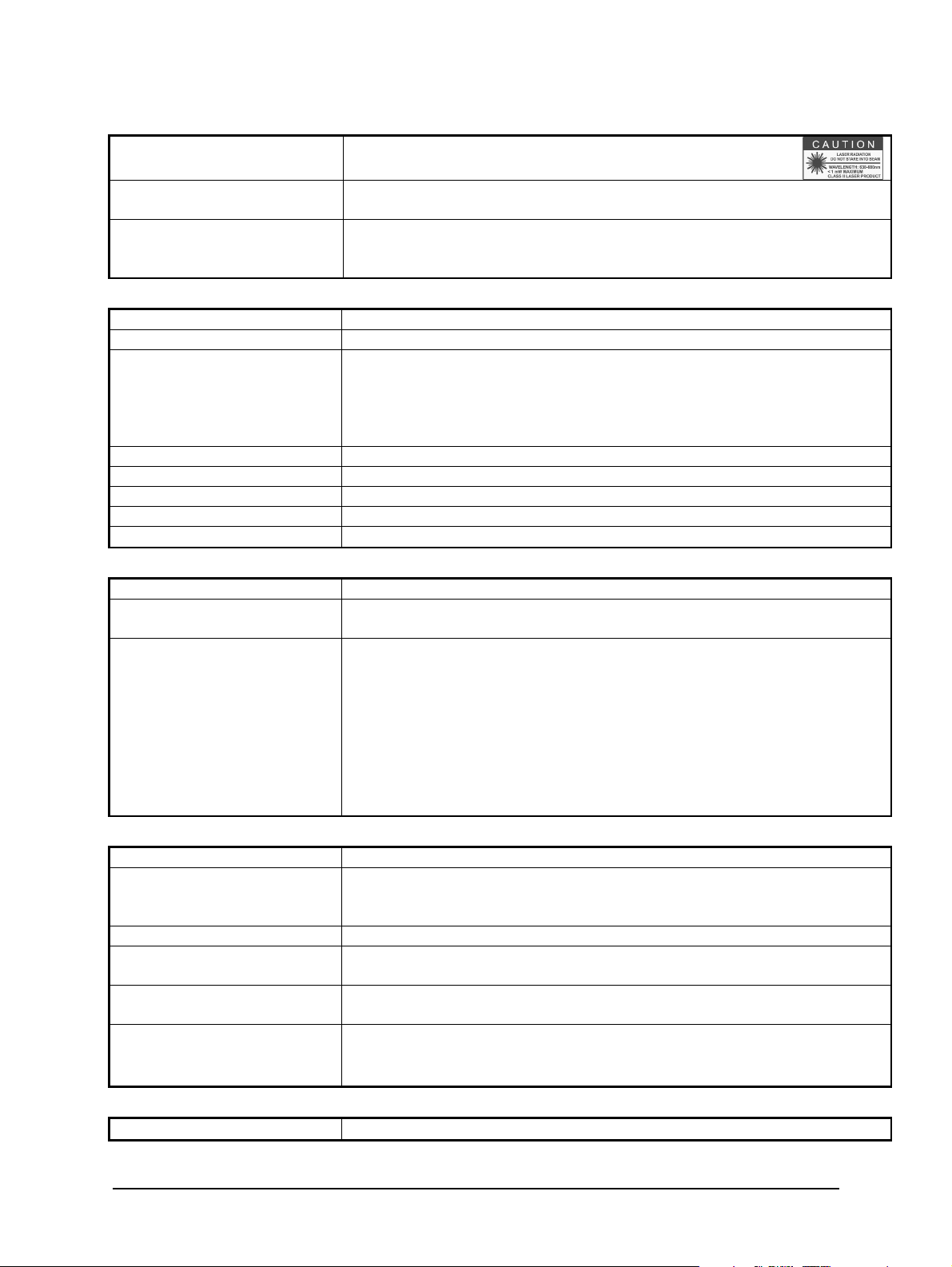
Sighting: Built-in laser aiming light (max. power level < 1 mW,
l = 630-680 nm, CDRH class II) or through-lens sighting
measuring distance a = 210 to 5000 mm
MB 18 approximately 190 : 1
MB 25 and MB 30 approximately 350 : 1
Environment
Protection Class: IP 65 IEC 60529 (value in mated condition)
Operating Position: Any
Ambient Temperature:
Note: During operation the
instruments will warm up and might
reach an intrinsic temperature of up
to 58 °C
0 to 65°C at housing
Storage Temperature: -20 to + 80°C
Weight: 0.6 kg
Housing: Stainless steel
CE-label: According to EU directives about electromagnetic immunity
Interface
Connection: 12-pin connector
Communication
for 2-color or 1-color temperature signal or measuring distance
accordingly emissivity slope or emissivity, temperature sub range,
settings for maximum value storage, address, baud rate, switch off limit,
warning level lens contamination monitoring system, transmittance,
response time t90, 0 to 20 mA or
4 or 20 mA analog output range, °C/°F.
Readable via interface: measured value, internal temperature of the
unit, measuring distance.
Baud rate: 1200 to 115.2 kBd
(on request RS232, not addressable)
level: 0 (off) to 99%
0.01 s; 0.05 s; 0.25 s; 1 s; 3 s; 10 s
Built-in single or double storage. Clearing with adjusted time t
(off; 0.01
clear
s; 0.05 s; 0.25 s; 1 s; 5 s; 25 s), via interface, automatically with the next
measuring object, external contact, hold-function
Electrical
ISR 6 Advanced Manual Introduction · 10
Page 11
Power
C
onsumption:
Max. 3 W ( incl. laser)
Load
(analog output)
:
0 to 500 W
Isolation:
P
ower supply, analog output and digital interface are electrically
with Through Lens
with Laser
All dimensions in mm
isolated from each other
Note: The calibration / adjustment of the instruments was carried out in accordance
with VDI/VDE directive “Temperature measurement in industry, Radiation
thermometry, Calibration of radiation thermometers”, VDI/VDE 3511, Part 4.4.
For additional details on this directive, see http://info.lumasenseinc.com/calibration or
order the directive from “Beuth Verlag GmbH” in D-10772 Berlin, Germany.
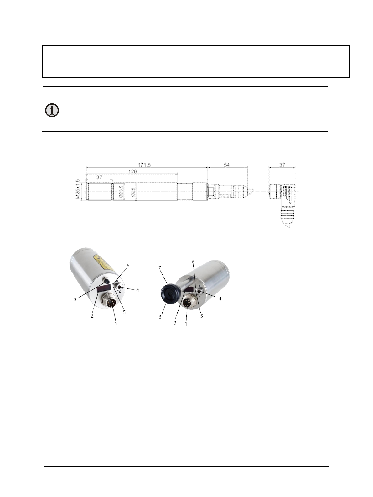
2.4 Dimensions
2.5 Physical User Interface
ISR 6 Advanced
1 12-Pin Connector
2 Digital Display
3 Sighting Option
4 Focus Adjustment
Set Screw
ISR 6 Advanced
5 LED Distance
Indicator Light
6 LED 1-Channel
Mode Indicator
Light
7 Viewfinder
Adjustment Ring
ISR 6 Advanced Manual Introduction · 11
Page 12
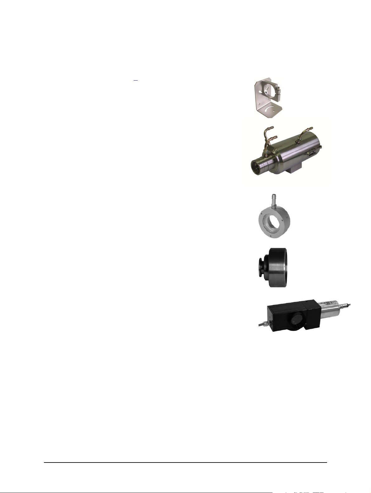
2.6 Accessories (optional)
The completely covered water cooling jacket is made from stainless
The pyrometer can be easily fixed o
n a vacuum chamber with the KF 16
Numerous accessories guarantee easy installation of the pyrometer. The following overview
shows a selection of suitable accessories. You can find the entire accessory program with all
reference numbers in Chapter 8, Reference numbers.
2.6.1 Mounting
An adjustable mounting angle is available to easily mount the
pyrometer and align it to the measured object.
2.6.2 Cooling Jacket
steel and serves to protect the pyrometer if exposed to a hot
environment. It is designed for ambient temperatures up to 180 °C.
2.6.3 Air Purge
The air purge protects the lens from contamination of dust and
moisture. It has to be supplied with dry and oil-free pressurized air and
generates an air stream shaped like a cone.
2.6.4 Vacuum support
vacuum support with sighting window.
Mounting Angle
Water cooling jacket with
integrated air purge
Air Purge
Vacuum
Support
2.6.5 Scanning Mirror
The scanning mirror unit SCA 5 allows the measured object to be
scanned over a certain range. The measuring beam of the pyrometer
moves straight in one line across the object and collects temperature
data of this line. This is useful when used in combination with the
maximum value storage (peak picker) to measure objects which move
out of the target area. The scanning angle of the mirror is 0 to 12° and
the scanning frequency 0 to 5 Hz. Both values are easily adjustable at
the scanner.
Scanning Mirror
2.6.6 Flange System
The flange system is a modular mounting system to fix the pyrometer on furnaces, vacuum
chambers, etc.
ISR 6 Advanced Manual Introduction · 12
Page 13
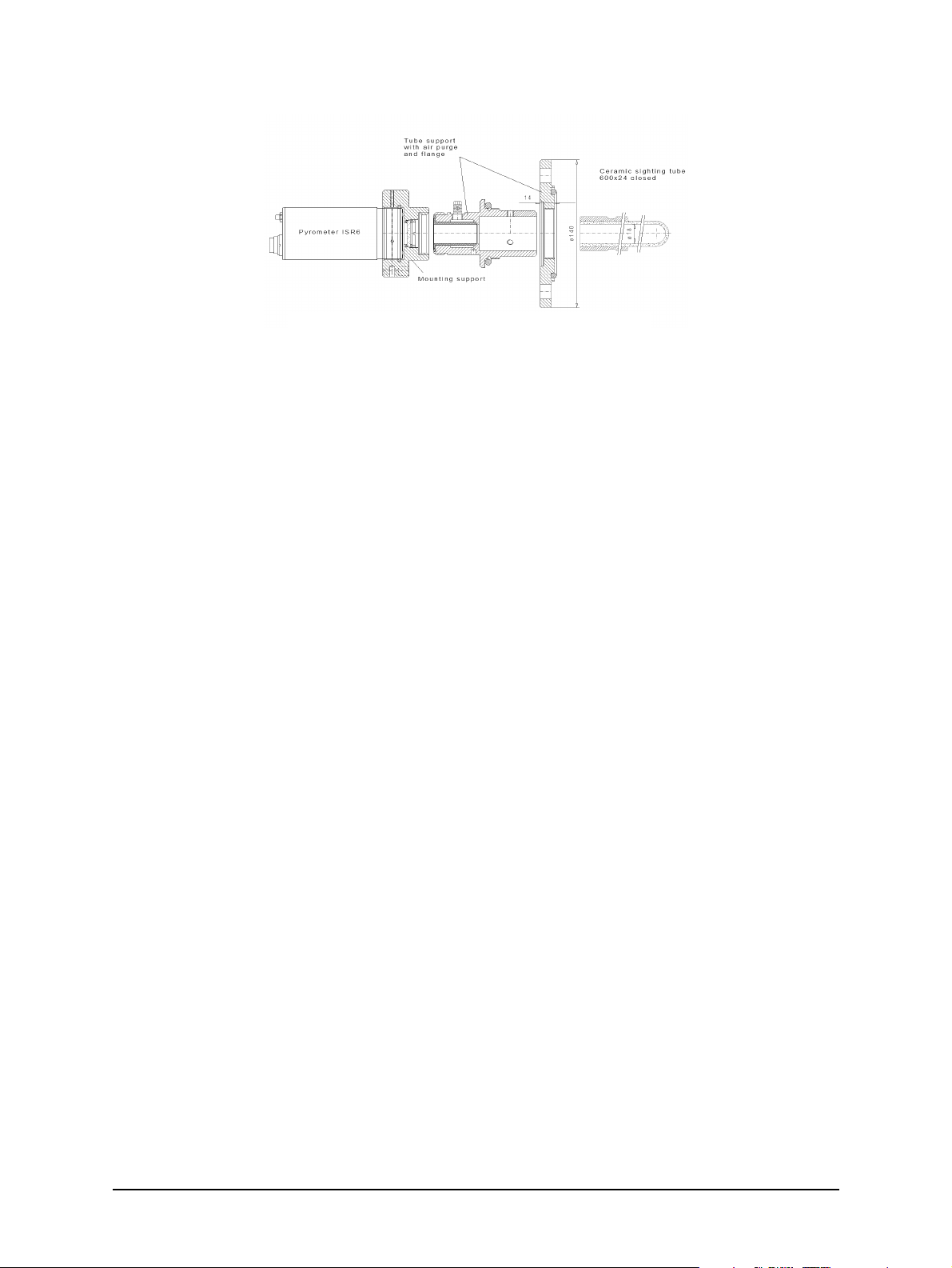
It can consist of e.g. mounting support, tube support with air purge and flange and an open or
Schematic dra
wing of the flange system
closed ceramic sighting tube. The mounting support can be equipped with a quartz window for
vacuum applications. It may consist of an equipment rack, flange, and an open or closed ceramic
tube. The equipment rack can be equipped for vacuum applications with a fused silica.
2.7 Transport, Packing, Storage
With faulty shipping, the instrument can be damaged or destroyed. To transport or store the
instrument, please use the original box or a box padded with sufficient shock-absorbing
material. For storage in humid areas or shipment overseas, the device should be placed in
welded foil (ideally along with silica gel) to protect it from humidity.
The pyrometer is designed for a storage temperature of -20 to 80 °C with non-condensing
conditions. Storing the instrument out of these conditions can cause damage or result in
malfunction of the pyrometer.
ISR 6 Advanced Manual Introduction · 13
Page 14

To ensure consistent document formatting, this page was intentionally left blank.
ISR 6 Advanced Manual Introduction · 14
Page 15
3 Controls and Installation
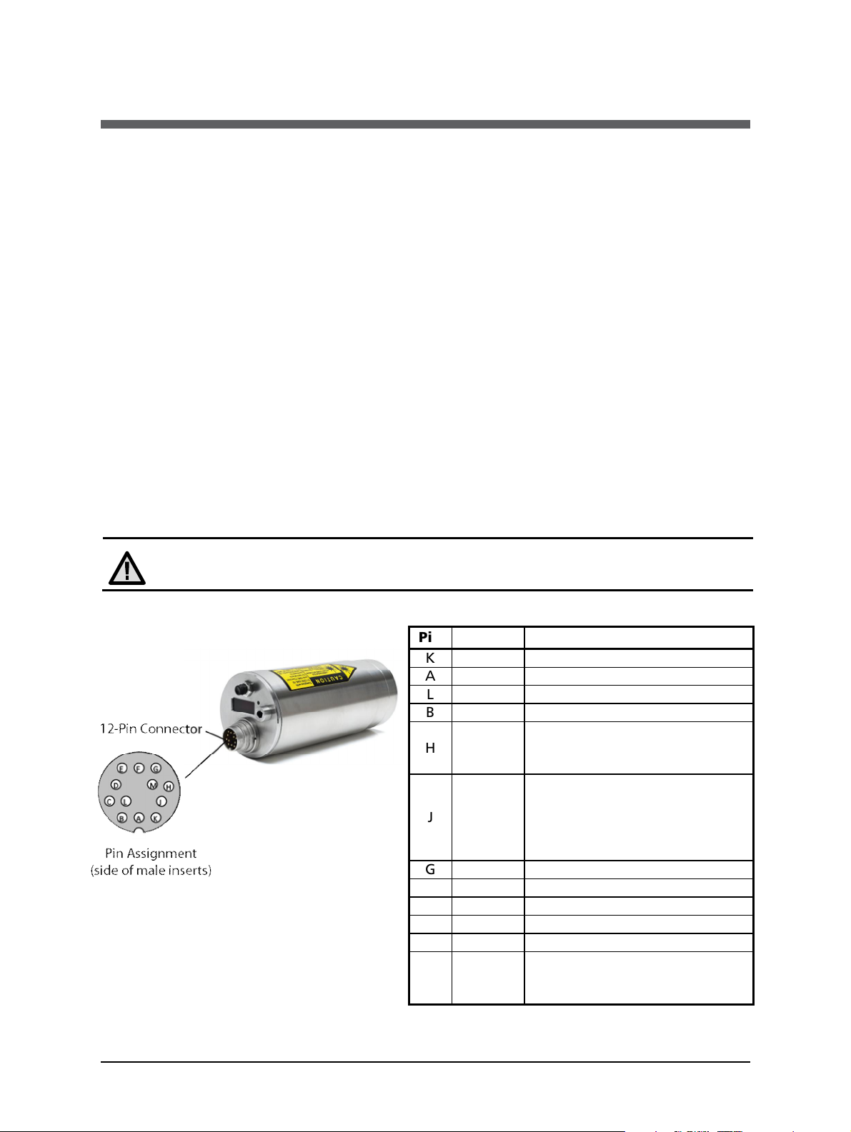
K
white
+24 V DC power supply
A
brown
0 V DC power supply
L
green
+ I
out.
analog output
B
yellow
–
I
out.
analog output
Targeting light activate /
External clearing of max. value
G
red
DGND
(GND for interface)
F
black
B1 (RS485) or RxD (RS232)
C
violet
A1 (RS485) or TxD (R
S232)
D
gray/pink
B2 (RS485) (bridged with F)
E
red/blue
A2 (RS485) (bridged with C)
Screen only for cable extension,
3.1 Electrical Installation
The pyrometer is powered by 24 V DC ± 25% (very well stabilized, ripple max. 50 mV). It is
important to ensure correct polarity when connecting the device to the power supply.
To meet the electromagnetic requirements (EMV), a shielded connecting cable must be used.
LumaSense offers connecting cables, which are not part of the standard scope of delivery.
The shield of the connecting cable has to be connected only on the pyrometer’s side. If the
connecting cable is extended, the shield of the extension also needs to be extended. The shield
must be open on the power supply side (switch board), to avoid ground loops.
The connecting cable has wires for the power supply, interface, analog output, external laser
switch, and external clear of maximum value storage via contact and 12 pin connector. The cable
includes a short adapter cable with a 9-pin D-SUB connector. This connector may be used in
combination with the RS485 to USB adapter.
Once the instrument has been connected to the power supply, it is immediately ready for use.
Although it does not need to be warmed up, it does need to run for approximately 15 to 30
minutes before achieving full accuracy. The instrument can be switched off by interrupting the
power supply or unplugging the electrical connector.
Attention:
When connecting the power supply, ensure the polarity is correct.
3.1.1 Pin assignment of the connector
Pin Color Function
H gray
J pink
deactivate via external switch
(bridged with K)
storage (bridge to K), hold
function, or output for “dirty
window” monitoring (*see
notes below)
ISR 6 Advanced Manual Controls and Installation · 15
M orange
don’t connect to the
switchboard
Page 16

The connector pin J can be used for 3 different functions:
1. External clearing of the maximum value storage:
When the pyrometer is in operating mode, pin J can be used for external clearing of
maximum value storage. When external clearing is selected from the t
menu, pin J is connected for a short time to pin K (power supply voltage) to clear the
stored maximum value.
The function “external clearing” is triggered with the following conditions:
· The clear time is set to “extern”.
· The “dirty window” warning system is switched off. This can be done through the
InfraWin software in the “color-bar” window.
· The warning level “dirty window” must be set to 0%.
2. Hold function:
When the hold function mode is activated, the current temperature reading is frozen as
long as pin J and pin K are connected. (See section 4.6 for clear time for the maximum
value storage).
3. “Dirty Window” Warning system:
The pyrometer is equipped with a “dirty window” warning system. The accuracy of the
pyrometer will be seriously affected if the lens is not clean and the sight path is obscured
by dirt, process material, smoke or steam (this can also happen if the object is smaller
than the spot size of the pyrometer).
dropdown
clear
To avoid incorrect measurements, a warning signal can be set to detect when the signal
level becomes too low or reaches a certain level. When activated, a built in relay (max.
continuous current 0.4 A) connects pin J to pin K (power supply voltage).
The setting of the warning level (0 to 99%) can be done through the “color-bar”
window of the InfraWin software. If the warning level “dirty window” is set to 0%
(factory setting), the “dirty window” warning system is switched off and pin J can
perform one of the functions of “external clearing” or “hold”.
The “dirty window” warning system is triggered with the following conditions:
· The clear time is not set to “extern” or “hold”.
· The pyrometer is operating in “2-color mode”.
3.1.2 Connecting the pyrometer to a PC
The pyrometer is equipped with an RS485 serial interface. With the RS485, long transmission
distances can be realized and the transmission is, to a large extent, free of problems. The RS485
also allows several pyrometers to be connected in a bus system.
If an RS485 connection is not available at the PC, it can be accomplished using the RS485 to USB
connector. When using a RS485 to USB adapter, make sure that the adapter is fast enough to
receive the pyrometer’s answer to an instruction of the master. Most of the commonly used
adapters are too slow for fast measuring equipment, so it is recommended to use the
LumaSense adapter (order no. 3 826 720).
ISR 6 Advanced Manual Controls and Installation · 16
Page 17
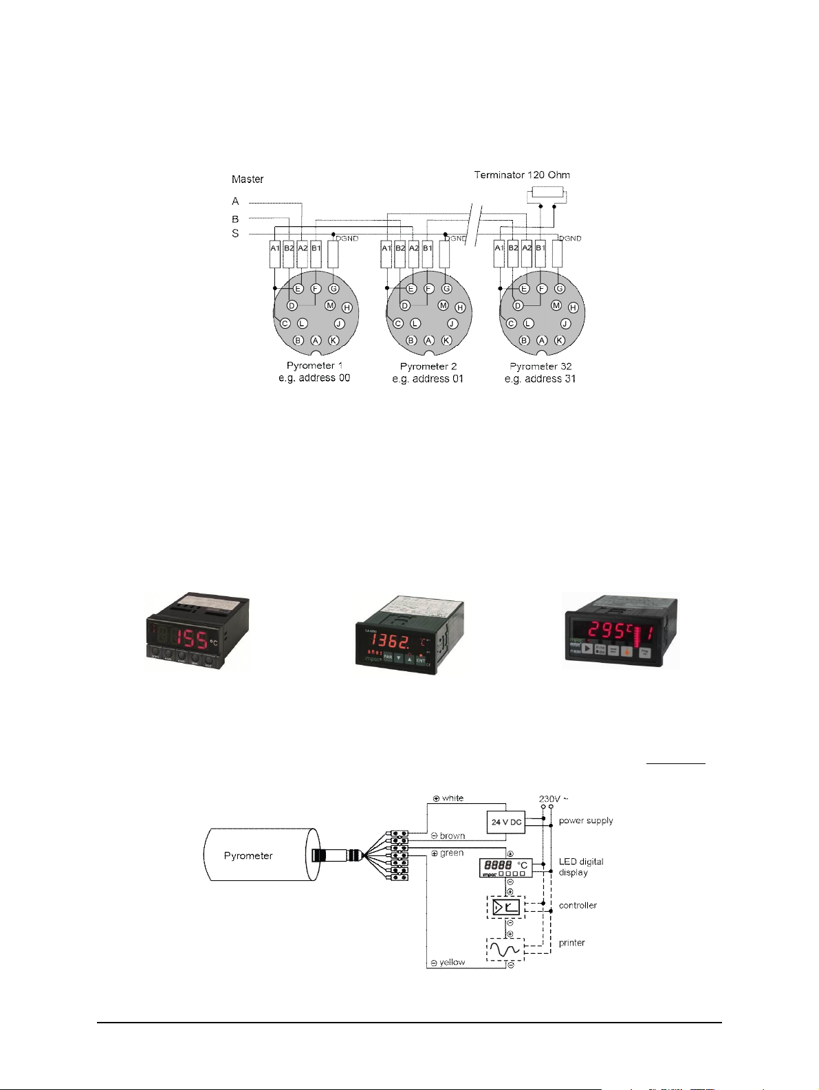
3.1.3 Connection to RS485
Half-duplex mode: A1 and A2 as well as B1 and B2 are bridged in the 12-pin round connector of
the connecting cable, to prevent reflections due to long stubs.
RS485 Bus System
It also safeguards against the interruption of the RS485 Bus System should a connecting plug be
pulled out. The master labels mark the connections on the RS485 converter. The transmission
rate of the serial interface in Baud (Bd) is dependent on the length of the cable. Values between
1200 and 115200 Bd may be set.
3.1.4 Connection schematic for analyzing devices
For temperature indication of the pyrometer, LumaSense offers pure indicators (series DA 4000).
LumaSense also offers indicators with features to change pyrometer parameters (DA 6000 and
DA 6000-N) as well as a fast digital PID controller PI 6000.
Digital Display Parameterizing Indicator Digital Controller
Additional analyzing instruments, including LED digital displays only need to be connected to a
power supply and the analog outputs of the pyrometer (exception: the digital display DA 6000
can also be connected with its serial interface, whereas the digital display DA 6000-N has to be
connected with its serial interface).
Connection Schematic for Analyzing Devices
ISR 6 Advanced Manual Controls and Installation · 17
Page 18
Instruments like an analog controller or printer can be connected to the display in a series as
shown above (total load of resistance max. 500 Ohm).
3.2 Sighting
The ISR 6 Advanced can be purchased with Through-Lens Sighting or with a Laser targeting
light. These sighting options allow you to easily align the pyrometer to the measuring object.
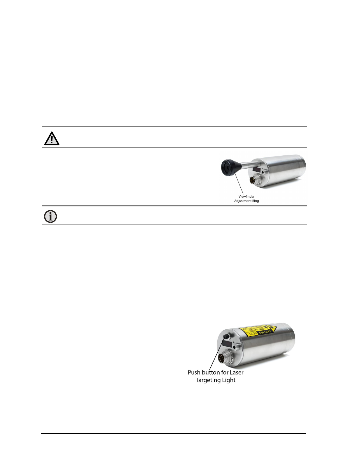
3.2.1 Viewfinder
The ISR 6 Advanced can be equipped with a viewfinder which offers through-lens sighting. The
viewfinder is true-sided and parallax-free. A circle marks the position of the measuring spot, but
not the exact spot size.
Warning: To ensure eye protection, make sure you use the shaded filter when viewing
objects with temperatures of 1500 °C or higher.
The viewfinder is equipped with an adjustable eye-protection
filter, which allows you to view hot objects without exposing
your eye to high intensity light. When you are viewing hot
objects, turn the adjustment ring on the viewfinder so the
filter will let in less light.
When you are viewing low temperature objects, turn the
viewfinder adjustment ring so the filter will let in more light.
Note: You can turn the adjustment ring on the viewfinder in both a clockwise and
counterclockwise direction to change the filter from light to dark.
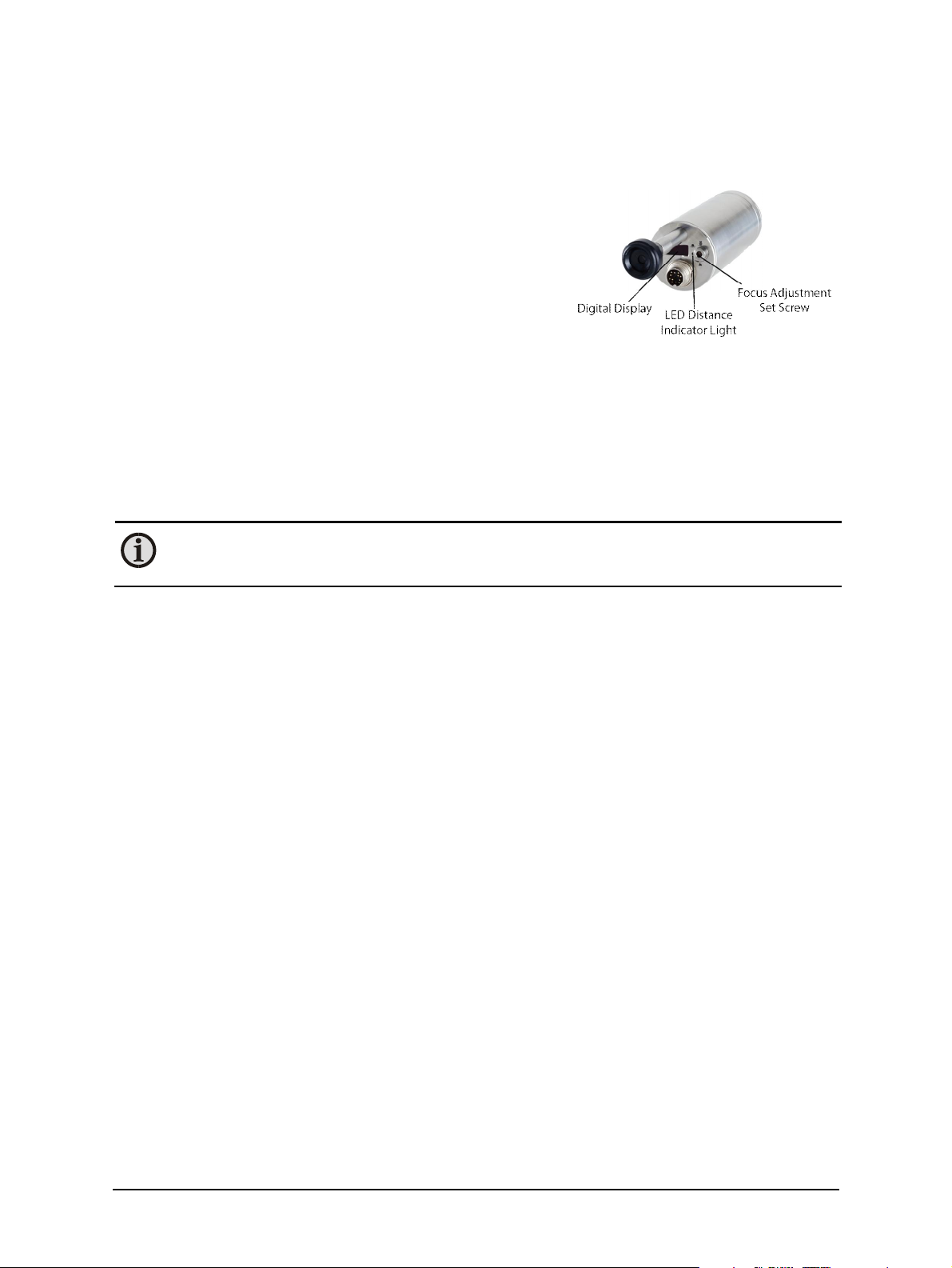
3.2.2 Laser Targeting Light
The ISR 6 Advanced can be equipped with a laser targeting light to assist with aligning the
pyrometer to the measuring object. The laser targeting light is a visible red light with a
wavelength between 630 and 680 nm and a maximum power of 1 mW. The laser is classified as
product of laser class II.
The laser spot marks the center of the measuring spot on the target. The diameter does not
correspond to the spot size. The smallest diameter of the laser spot approximately indicates the
measuring distance.
Never look directly into the laser beam. The beam and spot can be watched safely from side.
Also make sure that the beam will not be reflected into eyes of people by mirrors or shiny
surfaces.
The laser targeting light can be switched on and
off by pressing the button of the rear cover of
the housing.
The laser targeting light can also be switched on
and off by using an external contact (see section
3.1.1 “Connector Pin Assignment”) or through
the InfraWin software. If it is not switched off by
one of the above-mentioned methods, it will be
switched off automatically after approximately 2
minutes.
To prevent damage to the laser, the targeting light is also switched off automatically if the
internal temperature of the pyrometer exceeds 61 °C. It can only be used again once the
temperature falls below 61 °C.
ISR 6 Advanced Manual Controls and Installation · 18
Page 19

Note: The laser warning signs on the pyrometer should be easily viewable at all times,
Temperature Range
600 …
700 …
800 …
1000 …
Measuring Distance
2102.1
1.1
0.6
0.6
30031.6
0.9
0.9
50052.7
1.5
1.5
80084.2
2.3
2.3
1300
136.9
3.7
3.7
2000
20
10.6
5.8
5.8
5000
502715
15
even after it has been installed.
Laser Beam Safety Warning: The instrument is equipped
with a class II laser that emits radiation. To reduce the risk of
injury to the eyes, do not look directly into the targeting laser
and do not point the targeting laser into anyone's eyes.
3.3 Optics
3.3.1 Spot Sizes
The ISR 6 Advanced has a Vario optics, which can be manually adjusted at all distances between
210 mm and 5000 mm.
The table of spot sizes in relation to measuring distance shows examples of the pyrometer’s spot
size M [mm] in relation to the measuring distance a [mm] (min. 90% of the radiation intensity).
Increasing or decreasing the measuring distance will change the spot size.
Aperture D for all temperature ranges is 13 to 15 mm with the aperture being the effective
diameter of the lens. This is dependent on the optical setting. The largest value applies to a very
small measuring distance, while the minimum value applies to the largest measuring distance.
Note: In the 1-color (mono) mode, the pyrometer can measure objects at any distance
(whether focused or non-focused). However, the object has to be bigger than or at
least as big as the spot size of the pyrometer in the measuring distance.
In the 2-color (ratio) mode, the object can be somewhat smaller than the spot
diameter.
1400 °C
a [mm]
1800°C
Spot Diameter M [mm]
2500°C
3000°C
ISR 6 Advanced Manual Controls and Installation · 19
Examples of Spot Sizes in Relation to Measuring Distance
Page 20

Focused spot sizes between the listed distances can be found by linear interpolation between
the listed values. For example, for range 600 to 1400 °C, the spot size at 1600 mm distance
would be about 16 mm.
Note: Effective aperture D for all temperature ranges is 12 mm (focused to longest
distance) to 16 mm (focused to shortest distance).
3.3.2 Deviation from the focused measuring distance
Spot sizes for non-focused distances (shorter or longer than the focused distance) may be
calculated by using the formula below.
Formula for Calculating Spot Sizes
The InfraWin software also includes a Spot Size Calculator that calculates the data for the
non-focused regions, if you enter the values of aperture D, focused measurement distance a,
and focused measuring field diameter M as found in the above table (see section 3.3.1).
3.3.3 Adjusting the required measuring distance
The measuring distance can be set using the Focus
Adjustment Screw on the back of the device. The
focused distance value can be adjusted at all distances
between 210 mm and 5000 mm. To focus, turn the focus
adjustment set screw to make the target image appear
sharp and clear.
The LED Distance Indicator Light (labeled mm) will turn
red and the approximate focused measuring distance in
mm will automatically be shown on the Digital Display for a few seconds after making an
adjustment using the Focus Adjustment Set Screw.
Note: The optics are manually focusable with a measuring distance of a = 210 to
5000 mm.
Note: Turning the focus adjustment screw counterclockwise will shorten the
measuring distance.
Turning the focus adjustment screw clockwise will lengthen the measuring distance.
ISR 6 Advanced Manual Controls and Installation · 20
Page 21

4 Settings / parameter descriptions
The pyrometer is equipped with a wide range of settings for optimal adaptation to the required
measuring condition and to measure the temperature correctly.
The digital PC interface allows you to exchange data with a PC either by using the
supplied InfraWin software or by using the Universal Pyrometer Protocol (UPP)
commands with your own communication program (see Chapter 7 for the UPP Data
Format commands).
Selecting the pyrometer parameters window shows the current settings of the pyrometer. You
can change a value by typing a value in an input box or by selecting a preset value from the list
field.
The following settings can be made through the RS485 to USB connection.
4.1 Temperature Display
The Digital Display on the back of the pyrometer will show the temperature measurement in
either °C or °F. You can select which temperature scale you wish to use through the InfraWin
software or by using the UPP Data Format commands.
The Measuring Value can also be viewed at any time through the InfraWin Software or by using
the UPP Data Format commands
4.2 Emissivity ε
Different materials have different emissivities ranging between 0% and 100%. The emissivity is
also dependent upon on the surface condition of the material, the spectral range of the
pyrometer, and the measuring temperature. The emissivity setting of the pyrometer has to be
adjusted accordingly.
Emissivity settings between 20% and 100% can be established through the InfraWin software or
by using the UPP Data Format commands.
Note: Emissivity e Settings: 5% to 100% in steps of 1/1000 (1-color mode).
4.3 Emissivity Slope K
In 2-color (ratio) mode, the pyrometer is measuring simultaneously with 2 sensors in adjacent
wavelengths. It calculates the temperature by ratioing the radiation intensities of the two
wavelengths. This ratio technique eliminates a number of factors that degrade the accuracy of
conventional 1-color instruments. For example, with ratio pyrometers, measurement is
independent of emissivity in wide areas. They are also unaffected by dust in the field of view
and unaffected by dirty viewing windows or lenses, etc. as long as these disturbances are “grey”
(not colored).
In some cases the emissivities of the two wavelengths can differ so that it is necessary to correct
the ratio of the two emissivities (K = e1 / e2) to get a correct temperature reading. This
correction can be done by adjusting the emissivity slope setting K using the InfraWin software or
the UPP data format commands.
The K-factors of metals are normally slightly higher than 1. For a correct measuring result, it is
recommended that you make a comparison test. This comparison test may be performed by
ISR 6 Advanced Manual Settings / parameter descriptions · 21
Page 22

using a thermocouple probe or by knowing one process temperature point precisely from other
sources. The K-factor can then be adjusted until the pyrometer shows the same temperature
value.
The ISR 6 is factory calibrated for graybody targets that exhibit equal changes in emissivity
within its two spectral bands.
Note: Emissivity Slope K Settings: 0.800 to 1.200 in steps of 1/1000 (2-color mode).
4.3.1 Slope Adjustment
In some cases the emissivities of the two wavelengths can differ so that it is necessary to correct
the ratio of the two emissivities (K = e1 / e2) to get a correct temperature reading. This
correction can be done by adjusting the emissivity slope setting K using the InfraWin software or
the UPP data format commands.
The K-factors of metals are normally slightly higher than 1. For a correct measuring result, it is
recommended that you make a comparison test. This comparison test may be performed by
using a thermocouple probe or by knowing one process temperature point precisely from other
sources. The K-factor can then be adjusted until the pyrometer shows the same temperature
value.
The ISR 6 Advanced is factory calibrated for graybody targets that exhibit equal changes in
emissivity within its two spectral bands.
4.3.2 Temperature Errors Cause by Non-Graybodies
A graybody target has emissivity that is the same at each of the two wavelengths used for
measurements and is constant throughout the temperature range. The ratio of the emissivities,
e1 / e2= 1 and stays constant regardless of the target temperature. When a target deviates from
this, that is when e1 / e2 does not equal 1.0 and a slope adjustment is required. For many
materials, this is a one-time adjustment.
The following table illustrates the ISR 6 reading errors that can occur when the slope setting
differs from the actual material emissivity ratio.
TABLE OF EXPECTED ERROR WHEN EMISSIVITY OF ONE
WAVELENGTH IS 1% DIFFERENT FROM THE SECOND WAVELENGTH
TEMPERATURE ERROR DEG.
°F °C °F °C
1300 700 18 10
1500 815 20 11
1700 926 22 12
1900 1040 25 14
2100 1150 25 14
2300 1260 27 15
2500 1370 29 16
3000 1650 36 20
3500 1925 45 25
4000 2200 54 30
5000 2760 72 40
ISR 6 Advanced Manual Settings / parameter descriptions · 22
Page 23

The table shows typical errors that can result when the emissivity of one wavelength differs
from the other wavelength by only 1%. The errors can get quite large as temperatures increase.
This error can be much larger than a 1-color IR pyrometer would produce for 1% emissivity
change. Therefore, it is important to select the proper mode (2-color vs. 1-color) on the ISR 6 to
measure a specific material.
Another source of error is dust or smoke in the optical path which alters the transmission in one
wavelength more than the other. If the “dust” transmits 1% less energy at wavelength 1 than at
wavelength 2, the error table above also applies. Since not all smoke, dust, or dense steam
transmits equally at each wavelength, errors may become larger than expected for a 2-color
instrument. Usually the smoke and dust are the result of the material being processed and can
be cleared from the sight path by a fan or air purge tube.
In some materials, the emissivity may change at different rates with material temperature. Some
materials exhibit great changes in emissivity with temperature or time as oxidation modifies the
surface finish of the material. Such materials are not suited for measurement with 2-color
instruments. When problems are compounded with spectrally absorbing dust or smoke
(described above), obtaining reliable temperature readings with any 2-color instrument may be
impossible. In cases like this, a single color instrument using the shortest wavelength possible
would be the better choice. If this problem is encountered, switch the ISR 6 to 1-color mode. In
some situations, the single color mode will outperform the ratio mode.
4.4 Transmittance t
Transmittance is a parameter that can compensate for signal loss due to external windows etc.
For example, if the emissivity of the material is 0.6 and the transmittance of an additional
window is 0.9, then the product would be 0.54 which is well inside the allowed range.
The product of transmittance and emissivity (t x e) must not be less than 20%.
Note: Transmittance t Settings: 5% to 100% in steps of 1/1000 (1-color mode)
4.5 Response Time (t90)
The response time t90 is the time interval for the analog output of the pyrometer to go from a
low temperature value up to 90% of the temperature step to a high value when measuring an
abrupt increase from said low to said high temperature.
Independently of this, the pyrometer performs a measurement every 10 ms and updates the
analog output. Slower response times can be used to achieve a constant temperature reading
for measuring objects that have rapidly fluctuating temperatures.
The response time is set using the InfraWin software or by using the UPP Data Format
commands. When the setting is set to min., the ISR 6 Advanced operates using a time constant
of <2 ms (with dynamic adaption at low signal levels). The response time can be extended to
0.01 s; 0.05 s; 0.25 s; 1 s; 3 s; 10 s.
Note: Settings for Response Time t90 : min, 0.01 s; 0.05 s; 0.25 s; 1 s; 3 s; 10 s
4.6 Clear Peak Memory (t
The integrated maximum value storage is activated when the parameter tclear is set to
something other than “OFF” or “HOLD”.
CLEAR
)
ISR 6 Advanced Manual Settings / parameter descriptions · 23
Page 24

If the maximum value storage is switched on, the highest last temperature value will always be
displayed and stored. As such, it may be beneficial to periodically clear and reset the stored
maximum values in order to obtain new temperature readings.
This storage also has to be cleared at regular intervals when fluctuating object temperatures
cause the display or the analog outputs to change too rapidly or when the pyrometer is not
constantly viewing an object to be measured.
Note: Settings for Clear Peak Memory t
: OFF, 0.01 s, 0.05 s, 0.25 s, 1.0 s, 5.0 s,
CLE AR
25.0 s, EXTERN, AUTO, HOLD
4.6.1 Single and Double Storage Modes
Depending upon the selected settings, the maximum value storage will either work in single
storage mode or in double storage mode.
Single Storage
Mode:
Double Storage
Mode:
Note: The maximum value storage setting coincides with adjustments made to the
response time.
The response time setting (working like a low-pass filter) is applied first. After that,
the maximum storage is processed. So when using both, the maximum storage takes
the peak of the signal that was previously smoothed by the response time filter.
Single storage mode is used when you want to reset the stored value using
an external impulse via one contact closure from an external relay (such as
between two measured objects). The relay contact is connected directly to
the pyrometer between pins J and K. This mode allows a new value to be
established after each impulse from the reset signal. Single storage mode
also comes into effect when the Clear Peak Memory t
is set to AUTO.
clear
Double storage mode comes into effect when selecting one of the reset
intervals. This mode utilizes two memories. With the first memory, the
highest measured value is held and is deleted alternately in the time
interval set (clear time). The other memory retains the maximum value
throughout the next time interval. The disadvantages of fluctuations in the
display with the clock frequency are thereby eliminated.
So when using both, the maximum storage takes the peak of the signal that was
previously smoothed by the response time filter.
4.6.2 Clear Time Settings
The following settings are available through the InfraWin software or by using the UPP data
format commands.
OFF When set to OFF, the maximum value storage is switched off and all new
temperature values are measured but not stored.
0.01s…25.0s If the clear time is set between 0.01 s and 25.0 s, the maximum value is
held in double storage mode. After the entered time, the value will be
cleared alternately from one of the storages, while the value of the other
storage is shown.
EXTERN
ISR 6 Advanced Manual Settings / parameter descriptions · 24
With the external clearing function, the storage operates in single storage
mode. The values are immediately cleared from the storage by contacting
the wires connected to pins J and K, if the EXTERN mode was selected.
Page 25

AUTO The AUTO mode is used for discontinuous measuring tasks. For example,
when objects are being transported on a conveyer belt and pass the
measuring beam of the pyrometer only for a few seconds. In this case, the
maximum value for each object has to be obtained.
With the AUTO mode, the maximum value is stored until a new hot object
appears in the measuring beam. The temperature, which has to be
recognized as “hot” is defined by the low limit of the adjusted sub range.
The stored maximum value will be deleted once the temperature of the new
hot object exceeds the low limit of the sub range by 1% (transition in
positive direction) or by at least 2 °C. This is also valid if the sub range equals
the basic range.
HOLD The HOLD function allows you to freeze the current temperature reading at
any moment. This feature is activated using an external switch that has been
connected between connector pins J and K.
The temperature reading will remain frozen as long as the contact remains
closed.
4.7 Analog Output
The analog output has to be selected according to the signal input of the connected instrument
(controller, PLC, etc.). If 4 to 20 mA is set, the analog output gives 3.9 mA for temperatures
below lower range limit.
Note: Settings for Analog Output : 0 to 20mA or 4 to 20mA
4.8 Relative Signal Strength
Relative signal strength stands for the product of emissivity, surface coverage, and transmission
of the material between the object and the pyrometer. Refer to Section 4.8 for more
information on Relative Signal.
4.9 “Dirty Window” Warning
The ISR 6 Advanced pyrometers are equipped with a warning level “dirty window” monitoring
system. A correct temperature measurement might be impossible if the ratio pyrometer is
working at a too low signal level. To avoid these wrong measurements in advance, a warning
signal can be set to a certain contamination level. A built-in relay switch can be used to switch to
a warning signal when the incoming radiation becomes too low.
The warning level can be set between 0 and 99%. 0% means the “dirty window” warning
system is switched off (factory setting) and the relay can perform the function external clearing
of maximum value storage, when it is activated (see section 4.6.2 Clear Time Settings).
Note: Settings for “Dirty Window” Warning: 0 (off) to 99%.
4.10 Minimum Intensity Switch-Off Level
The minimum intensity switch-off level is a function that is used to avoid measuring errors
caused by signals which are too low. This may e.g. be caused by a dirty viewing window, dust in
the field of view, or when the spot is not filled by the measuring object.
ISR 6 Advanced Manual Settings / parameter descriptions · 25
Page 26

Note: Settings for Minimum Intensity Switch-Off Level: 2% to 50%
Ratio pyrometers are able to measure temperatures correctly even with very low signals. If the
signal is too low for a correct measurement, the pyrometer interrupts the measurement and
displays 1 °C below of beginning of the temperature range.
Although the factory default is set to 10%, switch-off limit can be adjusted between 2 and 50%,
depending on the application.
Note: The smaller the value, the higher the chance that daylight or reflections will
affect a correct temperature measurement.
4.11 Operating Modes
Ratio (2-color) mode is the factory default operating mode for the ISR 6 pyrometer. However,
the device can be set to mono (1-color) mode using the InfraWin software or by using the UPP
Data Format commands.
With 1-color mode, the device adjustments are simplified by
sending the emissivity corrected one channel temperature to the
analog output.
For a correct measurement in the 1-color mode, it is necessary to
adjust the emissivity using the InfraWin software or by using the
UPP Data Format commands. This emissivity is the relationship
between the emission of a real object and the emission of a
blackbody radiation source (this is an object which absorbs all
incoming rays and has an emissivity of 100%) at the same
temperature.
4.12 Sub Range
You have the opportunity to choose a sub range (minimum span 50 °C) within the basic
measuring range of the pyrometer. This sub range corresponds to the analog output.
Example: Range 700…1800 °C, Sub Range 925…975 °C.
The sub range setting also affects the maximum value storage when the Clear Peak Memory
t
is set to AUTO. For more information on the t
clear
Note: Settings for Sub Range: Any range adjustable within the temperature range
with a minimum span of 50 °C.
AUTO setting, refer to Section 4.6.
clear
4.13 Device Address
When connecting several pyrometers to one serial interface with RS485, it is necessary for each
instrument to have its own device address for communication purposes. First, it is necessary to
connect each instrument separately to give it an address. After that, all instruments can be
connected and addressed individually.
Note: Settings for Device Address:
Individual Addresses: 00…97 Global Addresses: 98, 99
Only via own communication program with interface command (not possible with
InfraWin, because InfraWin automatically detects a connected pyrometer): If parameters should
be changed simultaneously on all pyrometers, the global Address 98 can be used. This allows
ISR 6 Advanced Manual Settings / parameter descriptions · 26
Page 27
you to program all pyrometers at the same time, regardless of the addresses that have already
been assigned. If the address of a pyrometer is unknown, it is possible to communicate with it
using the global Address 99 (connect only one pyrometer).
4.14 Focused Distance
The focused distance value can be adjusted at all distances
between 210 mm and 5000 mm using the Focus Adjustment
Screw on the back of the device.
The LED Distance Indicator Light will turn red and the
focused measuring distance in mm will automatically be
shown on the Digital Display within a few seconds of
making an adjustment using the Focus Adjustment Set Screw.
The focused distance can be viewed at any time through the InfraWin software or by using the
UPP Data Format commands.
4.15 Baud Rate
The transmission rate of the serial interface in Baud (Bd) is dependent on the length of the
cable. A maximum cable length for 19200 Bd with RS485 is 2 km. The baud rate is reduced by
50% if the transmission distance is doubled.
Note: Settings for Baud Rate: 1200, 2400, 4800, 9600, 19200, 38400, 57600, or
115200.
4.16 Pyrometer Internal Temperature
The internal temperature of the pyrometer can be read through the PC interface using the
InfraWin software or by using the UPP Data format commands. It is a few degrees higher than
the ambient temperature due to the heat generated by the electronics.
When using the Laser Targeting Light, the targeting light is switched off automatically if the
internal temperature of the pyrometer exceeds 55 °C. This safety feature is used to prevent
damage to the laser. It can only be used again once the temperature falls below 55 °C.
ISR 6 Advanced Manual Settings / parameter descriptions · 27
Page 28

To ensure consistent document formatting, this page was intentionally left blank.
ISR 6 Advanced Manual Settings / parameter descriptions · 28
Page 29
5 Software InfraWin
The operating and analyzing InfraWin software is included with delivery of the pyrometer. In
addition to allowing you to make parameter adjustments, the InfraWin software also provides
temperature indication, data logging, and measurement analysis features.
This section gives an overview about the functions of the software. It also provides a description
of the individual icons found in the program's help menu. Click on the F1 button after loading
InfraWin or click on the ? in the menu bar.
The following descriptions refer to software InfraWin version 5.0. The latest version is available
for free as download from the homepage www.lumasenseinc.com.
5.1 Connecting the pyrometer to a PC
The program InfraWin can operate up to two devices. Two devices using RS485 may be operated
simultaneously by the same interface, if two different addresses have been properly entered
(see section 4.13 Device Address for more information).
5.2 Installation
To install the InfraWin software, select setup.exe from the InfraWin-CD or from the downloaded
and unpacked zip file from the internet and then follow the installation instructions.
5.3 Program start
The first time you load InfraWin 5, you will be prompted to select a default language. The
InfraWin software is available in German, English, Spanish, French, Portuguese, and Chinese.
Once installed, click Language/Languages if you would like to select another language.
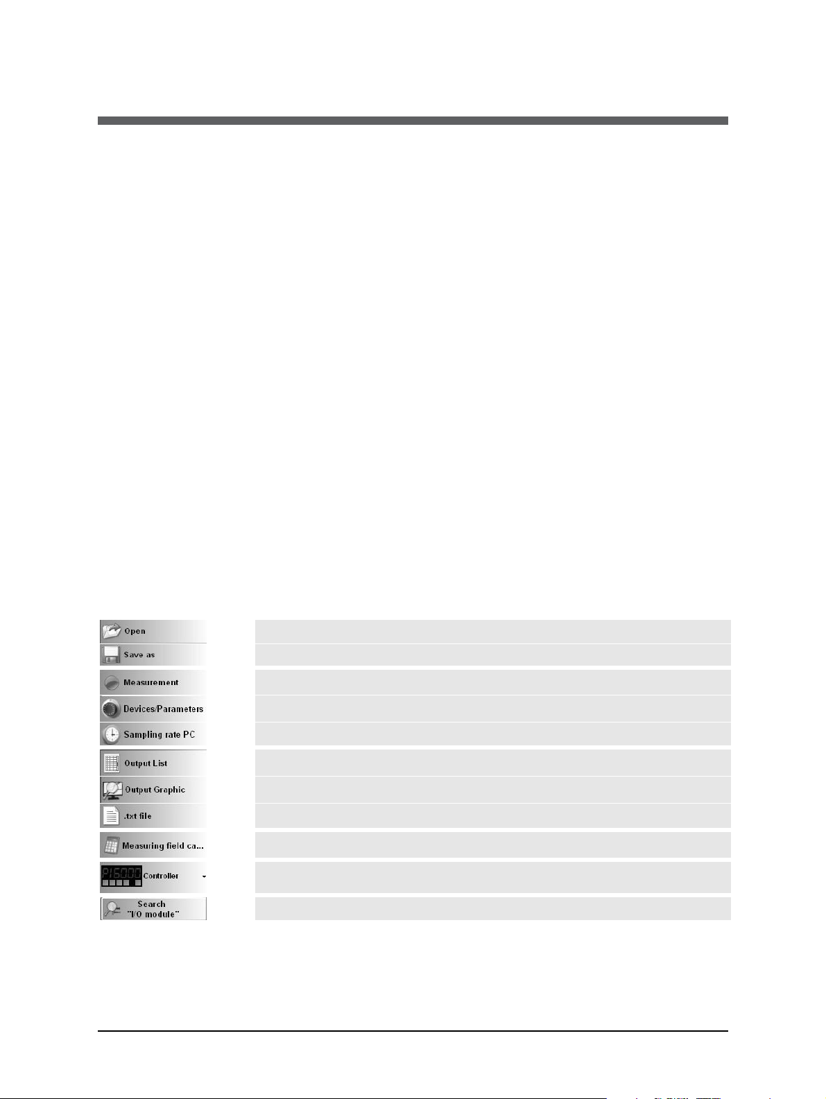
On the start page, the screen shows the following start menu icons.
Opens a saved file
Storage of measured values for further processing
Starts measurement for the selected device
Setting of the parameters of the instruments
Time interval between two measurements
Listing of measured or stored values in tabular form
Processing of measured (stored) readings in graph form
Processing of measured (stored) readings in a text file
Calculation of spot sizes in various measuring distances
Only if available: controls the programmable controller PI 6000
Search I/O module
ISR 6 Advanced Manual Software InfraWin · 29
Page 30

5.4 Basic settings
All preset values for the device
can be displayed and modified,
if necessary under the
Devices/Parameters window.
Changing an existing pyrometer
setting can be accomplished by typing
a value in an input box or by selecting
a preset value from the list field.
Choose the correct settings for your
application from the displayed options.
This window contains the parameter
settings described in Chapter 4,
Parameters.
5.4.1 Open/Save
The open and save buttons enable you to save customized configurations, which can
then be opened and reused at any time.
5.4.2 1 measure…
The 1 measur… function shows the current measuring temperature in the
pyrometer parameters window for approximately 1 second.
5.4.3 Print
The print icon will generate a screenshot of the parameter form and allow you to
send it a printer.
5.4.4 Close
The close icon will close the pyrometer parameters window.
5.4.5 Test
Clicking on the Test
icon will open a
window that allows you to
directly communicate with the
pyrometer using the UPP
(Universal Pyrometer Protocol)
Data Format commands.
After entering an interface
command (00 is the adjusted
address ex works, ms is the
command reading
temperature value) and
clicking on Send, the window
shown to the right will be
opened.
This window already shows the answer of the pyrometer in 1/10°. The actual temperature
reading is 699.0 °C.
Len indicates the length of the answered data string, incl. Carriage Return (Chr(13)).
ISR 6 Advanced Manual Software InfraWin · 30
Page 31
In the lower part of the window, the connection with the preset baud rate can be checked. Here
the command was sent 100 times with 19200 baud. It has taken 0.800 seconds without
transmission errors.
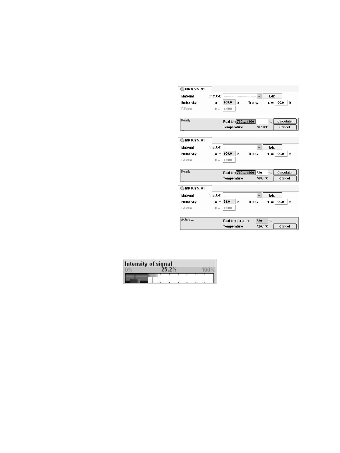
Emi: AutoFind: If the true temperature of the measured object is known, you can calculate the
emissivity of the measured object using the Emi: AutoFind function:
A measured temperature is displayed with the
current set emissivity (in this example 100%)
(here: 707.8 °C).
If you press Emi: Autofind a window will open
which allows you to enter the “true”
temperature (here 720 °C).
Once the temperature entry has been entered
and confirmed with Calculate, InfraWin will
then calculate the emissivity which occurs with
the new temperature (here 84.0%). This is
displayed immediately and can be used for
further temperature measurement.
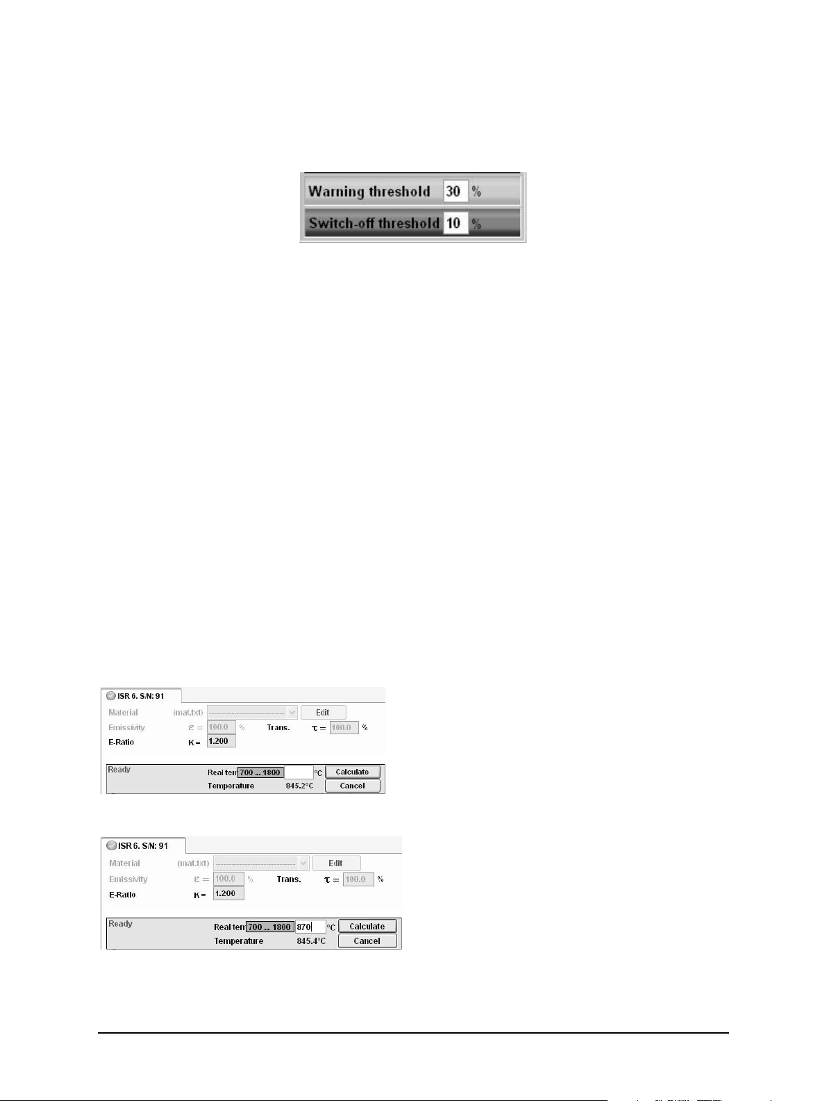
5.5 Relative Signal
The relative signal bar graph provides and indication of the signal strength.
InfraWin Software Relative Signal Indicator
In the above image, the relative signal bar indicates a signal intensity of 25.2%. This can be
caused by the object’s emissivity, contamination of the optics or viewing window, dust in the
field of view, or a small measuring object.
Normally, this bar graph is used to monitor if the signal level due to contamination of optics or
window decreases over time. It shows the measured intensity compared to the intensity a
blackbody radiation source would have at the determined ratio temperature of the pyrometer.
The shown relative signal depends on the entered emissivity slope K (a wrong adjustment results
in relative signals above 100%).
ISR 6 Advanced Manual Software InfraWin · 31
Page 32
5.6 Warning Level / Switch-Off Level
In addition to the relative signal bar graph, the warning level and the switch-off level are
indicated as vertical lines in colors corresponding to the windows below.
The ISR 6 pyrometers are equipped with a warning level “dirty window” monitoring system.
A correct temperature measurement might be impossible if the ratio pyrometer is working at a
too low signal level. To avoid these wrong measurements in advance, a warning signal can be
set to a certain contamination level. A built-in relay switch can be used to switch to a warning
signal when the signal becomes too low. When this happens, the built-in indicator of the
pyrometer starts blinking, but will continue the measurement.
The warning level can be set between 0 and 99%. 0% means the “dirty window” warning
system is switched off (factory setting) and the relay can perform the the function external
clearing of maximum value storage or external hold, when one of them is activated.
The switch-off level is a function used to avoid measuring errors caused by too low signals.
Ratio pyrometers are able to measure temperatures correctly even with very low signals. For
example, through a dirty viewing window, or if dust exists in the field of view, or if the spot is
not filled by the measuring object.
If the signal is too low for a correct measurement, the pyrometer interrupts the measurement
and displays 1° below the beginning of the temperature range. Although the factory default is
set at 10%, the switch-off limit can be adjusted between 2% and 50%, depending on the
application.
5.7 Emissivity Slope K: AutoFind
InfraWin also offers an input field K for the emissivity slope. If the emissivity is changed, the
temperature change connected with this can be directly affected.
If the true temperature of the measured object is known, you can calculate the emissivity slope
of the measured object using the K: AutoFind function:
A measured temperature is displayed with
the current set emissivity slope. In this
example, the emissivity slope is set at 1.000
and the resulting temperature reading is
845.2 °C.
If you press the K: Autofind button, a
window will open which allows you to
enter the true temperature.
In this example, we have entered a
temperature of 870 °C.
Once you enter the temperature value, you
can press the OK button to set the
temperature value and close the
temperature window.
ISR 6 Advanced Manual Software InfraWin · 32
Page 33

Once the temperature entry has been entered
and confirmed with OK, InfraWin will then
calculate the emissivity slope. The new
emissivity slope will immediately appear along
with the new temperature, which can be used
for further temperature measurement.
5.8 Measurement online trend
The measurement
function allows you to
access a number of input tabs located on
the left side of the screen. The main or
home tab is the Output Screen. You can
toggle the input tabs on and off by
clicking them. This window displays:
· temperature as graphical diagram
· internal temperature of the
instrument
· current temperature
· quantity of the measured values and file size of the current measurement
The example shows a sample reading over the period of approximately 15 seconds with a
temperature range between 699 and 713 °C. The final temperature (at the end of the reading) is
699.0 °C.
The Mark Zone button allows you to color mark a temperature range for easier recognition.
The Threshold button allows you to set a temperature value as a baseline to prevent recording
values above or below the baseline temperature. This allows you to keep the output file size
small.
The Scaling Trend button allows you to scale temperature trend view.
Note: The measuring values of “measurement online trend” are automatically saved
as "standard.i12". Should you need to edit the data later, you need to save the file as
another .i12-file because old values are over-written when a new measurement is
taken.
Files from older program versions (.i10-files) can be opened and saved as .i12.
5.9 Listing (analyzing)
For analyzing the
measured values in this
field, all measured data appears in a numeric
list.
The column between time and temperature
provides a time resolution of milliseconds.
The value specifies the time in seconds after
midnight (0:00 h). The amount of data
depends on the frequency that readings were
taken (settings at 5.9 PC sampling rates). As
ISR 6 Advanced Manual Software InfraWin · 33
Page 34

the amount of data increases, so does the amount of storage space required to save it. In order
to save room, all .i12 data files are stored by a binary code.
5.10 Output .TXT file (analyzing)
The same file as under Output listing may be converted into a text file and
can be easily opened, for example with Microsoft Excel. With the standard
import settings, Excel automatically formats the columns accordingly (with tabs as separators).
5.11 Trend output (analyzing)
The graph’s curve depicts the temperature
change over time within the specified
temperature range.
Additionally, other information appears in this
window; such as recorded time (x-axis) and
temperature in degrees (y-axis) as well as the
time and temperature at the vertical cursor line
which can be dragged with the mouse.
Selecting the Trend output initially causes all
the saved data to be displayed.
If the data exceeds an amount that can be reasonably represented, you may “Zoom“ in on a
partial segment using the mouse (such as the segment represented in the example). Under
“Total” you can return to the representation of the entire curve.
Note: The last reading is saved in the standard.i12 file and automatically appears in
this form upon opening Listing or Trend output.
Selecting file open with another file, the previous file will be overwritten and replaced by the standard.i12 file.
5.12 PC sampling rate (time interval between two
measurements)
This function sets a time interval. After
each interval, one measured value is
stored on the PC. Longer time intervals will result in
creating smaller stored file sizes. This function is mainly
used for long term measurements.
5.13 Spot size calculator
The InfraWin Spot Size Calculator
calculates the data for the nonfocused regions. To calculate data, enter the values
of aperture D, focused measurement distance a,
and focused measuring field diameter M as found
in the documentation relating to the optics
supplied with your specific pyrometer.
After entering the aperture and the main spot size,
the input of interim values calculates spot sizes in
different measuring distances of the fixed optics.
ISR 6 Advanced Manual Software InfraWin · 34
Page 35

5.14 Search I/O Module
The I/O Module allows
accessories to connect to
the software and is used to trigger
measurement externally or to send a signal
(like a relay) under certain conditions.
ISR 6 Advanced Manual Software InfraWin · 35
Page 36

To ensure consistent document formatting, this page was intentionally left blank.
ISR 6 Advanced Manual Software InfraWin · 36
Page 37

6 Maintenance
6.1 Cleaning ISR 6 Window
Because there are no moving parts in the ISR 6, the only regular maintenance required is a
periodic inspection of the front window for build-up of foreign particles which, in time, can
influence the energy received by the instrument. The ISR 6 has a “Dirty Window” warning alarm
feature that can measure the current window/optical path transmission and provide a contact
closure alert when the window transmission falls below the user set point.
The ISR 6 window is not water soluble and; therefore, can be cleaned with standard lens tissue
dampened with a camera-store lens-cleaning solution. A soft blower/brush (also at camera
stores) should be used to remove any grit on the window before you rub the lens with lens
tissue and solution.
Attention: NEVER CLEAN THE ISR 6 WINDOW WITH A DRY TISSUE OF ANY KIND!
The only time dry lens tissue may be used is to dry a window which has already been
cleaned with wet lens tissue.
6.2 Calibration
LumaSense calibrated your pyrometer at the factory and delivered your instrument with a
Works Certificate. Normally we advise against changing the factory set calibration. If you believe
that the calibration may have changed, perhaps because your operating environment is severe,
an approximate field (on-site) calibration is possible. You have the choice of an on-site
calibration or arranging a more precise calibration at the LumaSense factory.
6.2.1 Laboratory Calibration
Contact LumaSense for information about calibration at the LumaSense factory. For most of our
customers who do not have large numbers of infrared thermometers in service, we recommend
that our laboratory be chosen to do calibration. When you have many infrared thermometers,
you may find it most convenient and economical to have your own calibration laboratory.
LumaSense has a variety of blackbody calibration sources including very economical ones.
Among these you may find the source most suitable for your own laboratory.
6.2.2 On-Site Calibration
See the Chapter 9: Troubleshooting in this manual before attempting to perform your own
calibration. The instrument was calibrated at the factory to its original accuracy as stated.
Nearly all erroneous temperature readings are caused by application problems such as:
· Emissivity factor: Carefully read “Emissivity Slope K” found in section 4.2 of this
manual for information on this topic. Also use the InfraWin “K: AutoFind” function as
described in the InfraWin manual to determine the actual emissivity ratio of the target.
· Reflections: Unexpectedly high readings may be caused by the ISR 6 “seeing” a
reflection of another hotter source, especially if the target emissivity is less than 0.8.
· Spot Sizes: Ensure the ISR 6 is using a proper focused distance and takes into account
the spot size in relation to measuring distance.
ISR 6 Advanced Manual Data format UPPÒ· 37
Page 38

In the 1-color (mono) mode, the pyrometer can measure objects at any distance.
However, the object has to be bigger than or at least as big as the spot size of the
pyrometer in the measuring distance.
In the 2-color (ratio) mode, the object can be somewhat smaller than the spot
diameter.
Information on this topic can be found in Section 3.3 Optics and Section 4.14 Focused
Distance.
· Obscured window: Refer to Cleaning ISR 6 Window, Section 6.1.1.
ISR 6 Advanced Manual Data format UPPÒ· 38
Page 39

7 Data format UPPÒ (Universal Pyrometer
ud 1 = 2400 Baud 2 = 4800 Baud
6 = 57600 Baud 7 = is not allowed 8 = 115200 Baud
Protocol)
Software commands can be exchanged directly with the pyrometer through an interface using
suitable communication software or by using the Test function located in the Pyrometer
Parameters window of the InfraWin software package.
The data exchange occurs in ASCII format with the following transmission parameters:
• The data format is: 8 data bits, 1 stop bit, even parity (8,1,e) no handshake;
• The device responds to the entry of a command with output (such as the measuring
value) + CR (Carriage Return, ASCII 13), to pure entry commands with ok + CR, or no +
CR.
• Every command starts with the 2-digit device address AA followed by two lower case
command letters and finished with CR.
Example Read Command: Entry: “00em“ + CR
The emissivity setting (e) of the device with the address 00 is returned.
Answer: “0970“ + <CR> means Emissivity = 0.97 or 97.0%
• The ASCII parameter “X” indicates a change to be made in a parameter. When used, the
command contains the new value.
Example Write Command: Entry: “00emXXXX“ + CR
The parameter used for the emissivity setting (e) with the address 00 is changed.
Answer: “00em0853“ + <CR> changes the Emissivity to 0.853 or 85.3%
· A “?” after the lower case command letters answers with the limits of the respective
settings (only at setting commands, not at query commands).
Example Read Limits Command: Entry: “00em?“ + ˜CR!
Answer: Could be 00501000 + <CR>, which means that E can vary between 0.050 and
1.000 (or 5% and 100%)
Description Command Parameters
Analog output AAasX X=0 (0 to 20mA) X=1 (4 to 20mA)
Minimum intensity
switch-off level
Reference number AAbn Output: XXXXXX (hex 6-digit)
Baud rate (set) AAbrX X = 0 to 6 or 8 (dec.)
“Dirty Window”
Warning
AAawXX
AAaw
AAdwXX XX = 00 …99% (2 digit, hex.)
XX=02 to 50 (2% to 50%)
Answer: DD 2 decimal digit 02 to 50
0 = 1200 Ba
3 = 9600 Baud 4 = 19200 Baud 5 = 38400 Baud
ISR 6 Advanced Manual Data format UPPÒ· 39
Page 40

Description Command Parameters
3=0.25 s
7=EXTERN
Measuring value
(one-channel and
ratio temperature)
AAek Answer: SSSSSQQQQQ
2x5 decimal digits (in °C or °F, last digit is 1/10 °C or °F),
SSSSS = one-channel temperature
QQQQQ=ratio temperature
Emissivity e for onechannel temperature
Transmittance t of
window
K = e1 / e
2
Emissivity ratio
AAemXXXX
AAem
AAetXXXX
AAet
AAevXXXX
AAev
XXXX=0050 to 1000 e=0.050 to 1.000
Answer: DDDD 4 decimal digits 0050 to 1000
XXXX=0050 to 1000 t=0.050 to 1.000
Answer: DDDD 4 decimal digits 0050 to 1000
XXXX=0800 to1200 e1 / e2=0.800 to 1.200
Answer: DDDD 4 decimal digits 0800 to 1200
Response time t90 AAezX X=0 to 6 0=min. 1=0.01 s 2=0.05 s
4=1.00 s 5=3.00 s 6=10
Temp. Display °C or °F AAfhX Output: X = 0 display in °C
X = 1 display in °F
Device Address: AAgaXX XX = (00 to 97)
00 to 97 = regular device addresses
98 = global address with response
99 = global address with response
internal temperature
(read)
AAgt
AAtm
Answer: DDD 3 decimal digits (000 to 098 °C or
032 to 210 °F)
gt=current temp. tm=maximum temp. (memory)
Operation mode AAkaX X = 1 mono mode (1 channel)
X = 2 ratio mode (2 channel)
Laser AAlaX
AAla
Software simulation
AAlx Clears maximum storage
X=0 off X=1 on
Answer: 1 digit: “0” or “1”
of external clearance
Clear peak memory
t
clear
AAlzX X=0 to 8 0= OFF 1=0.01s 2=0.05s 3=0.25s
4=1.0s 5=5.0s 6=25.0s
8=AUTO 9=HOLD
Basic range (read) AAmb Answer: XXXXYYYY
2x4 hex-digit for lower and upper range limit (°C or °F)
Sub range (read) AAme Answer: XXXXYYYY
2x4 hex-digit for lower and upper range limit (°C or °F)
Sub range (set) 1. AAm1XXXXYYYY XXXXYYYY=2x4 hex-digit for lower and upper sub range
limit (°C or °F)
2. AAm2 AAm2 confirms the change (auto reset)
Measuring value AAms Answer: QQQQQ (88880=Overflow)
5 decimal digit (in °C or °F, last digit is 1/10 °C or °F)
Device type AAna Output: “ISR 6 Advanced ” (16 ASCII-characters)
ISR 6 Advanced Manual Data format UPPÒ· 40
Page 41

Description Command Parameters
Read parameters AApa Answer: 15 decimal digits
DD . . . . . . . . . . . . . : Emissivity (see em)
. . D . . . . . . . . . . . . : Response time (see ez)
. . . D . . . . . . . . . . . : Clear peak memory (see lz)
. . . . D . . . . . . . . . . : Analog output (see as)
. . . . . DD . . . . . . . . : Internal temperature (see gt)
. . . . . . . DD . . . . . . : Device address (see ga)
. . . . . . . . . 4 . . . . . . : Baud rate (see br)
. . . . . . . . . . 0 , , , , : always 0
. . . . . . . . . . . DDDD : Ratio correction (see aw)
Serial number AAsn Output: XXXXX (hex 5-digit)
Read signal strength* AAtr Answer: DDDD 4 decimal digit 0000 to 1500
Device type/
software version
Communication
Module/ software
version in detail
Software version in
detail
AAve Answer: VVMMJJ VV=54
MM=Month JJ=Year of software version
AAvc tt.mm.jj XX.YY
tt = day; mm = month; yy = year;
XX.YY = software version
AAvs tt.mm.yy XX.YY
tt = day; mm = month; yy = year;
XX.YY = software version
*Read Signal Strength stands for product of emissivity, surface coverage and transmission of the measuring distance.
Note: the lett er “l” means the lower case letter of “L”.
Additional instruction for the RS485 interface:
Requirements to the master system during half-duplex operation:
1. After an inquiry, the bus should be switched into a transmission time of 3 bits (some
older interfaces are not fast enough for this).
2. The pyrometer's response will follow after 5 ms, at the latest.
3. If there is no response, there is a parity or syntax error and the inquiry has to be
repeated.
4. After receiving the response, the master has to wait at least 1.5 ms before a new
command can be entered.
ISR 6 Advanced Manual Data format UPPÒ· 41
Page 42

To ensure consistent document formatting, this page was intentionally left blank.
ISR 6 Advanced Manual Data format UPPÒ· 42
Page 43
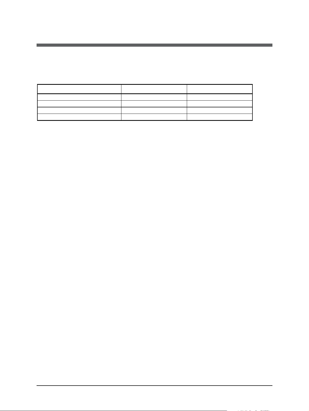
8 Reference Numbers
600 to 1
400
°C (MB14)
3 904 020
3 904 010
700 to 1800
°C (MB 18)
3 904 080
3 904 070
800 to 2500
°C (MB 25)
3 904 150
3 904 140
1000 to 3000
°C (MB 30)
3 904 220
3 904 210
8.1 Reference numbers instrument
Temperature Range With Viewfinder With Laser Targeting
Ordering note:
A connection cable is not included in scope of delivery and has to be ordered separately.
8.2 Reference numbers accessories
3 820 320 Special connection cable with angled connector and additional targeting light
push button, 5 m long
3 820 330
3 820 500
3 820 510
3 820 810
3 820 820
3 820 520
3 820 340
3 820 530
3 820 540
3 820 830
3 820 840
3 820 550
3 826 510 PI 6000: PID programmable controller, very fast, for digital IMPAC pyrometers
3 826 720 USB to RS485 adapter cable, 1.8 m long
3 834 210 Mounting support (adjustable)
3 835 160 Air purge unit, aluminum
3 835 590 90° mirror for Series 5 and Series 6, quartz glass window
3 837 230 Water cooling jacket (heavy duty) with integrated air purge
3 843 250 ROT5 scanning mirror attachment up to 70°
5m connection cable with straight connector
10m connection cable with straight connector
15m connection cable with straight connector
20m connection cable with straight connector
25m connection cable with straight connector
30m connection cable with straight connector
5m connection cable with right angle connector
10m connection cable with right angle connector
15m connection cable with right angle connector
20m connection cable with right angle connector
25m connection cable with right angle connector
30m connection cable with right angle connector
(All connection cables include a
short adapter cable with a 9-pin
D-SUB connector. This
connector may be used in
combination with the RS485 to
USB adapter.)
3 843 490 SCA 5, External Scanner Series 5 & 6 with fused silica window; 24V AC/DC
3 846 260 Mounting support
3 846 290 Mounting support with fused silica window
3 846 590 Vacuum support KF16 with quartz glass window
3 852 290
ISR 6 Advanced Manual Reference Numbers · 43
Power supply NG DC for DIN rail mounting; 100 to 240 V AC Þ 24 V DC, 1 A
Page 44

3 852 550
Power supply NG 2D for DIN rail mounting; 85 to 265 V AC Þ 24 V DC, 600 mA
with two settable limit switches
3 890 640 DA 4000-N: LED-digital display to be built into the switchboard
3 890 650 DA 4000: like DA 4000-N, but additionally with 2 limit switches
3 890 570 DA 6000-N digital display to allow adjustment of the Pyrometer through the
RS485 interface.
3 890 530 DA 6000: like DA 6000-N with analog input and 2 limit switches for the RS485
interface
3 890 630 LD24-UTP; large digital indicator, 57 mm height of digits
ISR 6 Advanced Manual Reference Numbers · 44
Page 45

9 Troubleshooting
Symptom Probable Cause Comments
No analog output even
if the display shows a
temperature above
lower range limit
Temperature reading
differs between built-in
display and external
instrumentation
Temperature readings
are too low
Reversed leads to ISR 6. The ISR 6 is diode protected if
Reversed leads to other
instruments
in the current loop.
Open circuit in lines connecting
all instruments in current loop.
Total burden higher than 500
Ohms
Insufficient supply voltage (See
wiring diagram).
Pyrometer output setting differs
from external instrument’s input
setting
Target size too small.
Target is not at correct focus
distance.
power leads are reversed.
See section 3.1
Check the 0 to 20 mA or
4 to 20 mA on both sides
Check the sub range setting on
pyrometer against the range
setting on the external
instrument
See sections 3.4, 3.5, and 5.2.11
With small target/close focus
models, aiming may require X-Y
positioning table for fine
adjustment during aiming.
Incorrect alignment of the
pyrometer to the object.
Dirty window or lens. See sections 4.9 and 6.1
Target temperature too low.
Target emissivity much lower
than expected.
Incorrect slope adjustments. See sections 6.3 and 5.2.4
Faulty ISR 6 Contact LumaSense. See section
ISR 6 Advanced Manual Troubleshooting · 45
Realign pyrometer in 1-channel
mode (mono) to achieve the
maximum temperature signal.
Even 2-Color instruments
depend on actual target
emissivity to supply sufficient
energy to the sensor.
See sections 4.2, 4.3, 4.4, 4.8,
and 6.1
2.5
Page 46

Symptom Probable Cause Comments
Temperature readings
are too high
Targets hotter than expected.
(This often happens with first
time infrared Pyrometer users).
Verify target temperature with
contact type method.
(Thermocouples may not
accurately determine surface
temperature due to “heat sink”
effect).
Incorrect slope adjustments. See sections 6.3 and 5.2.4
Target size is too small See sections 3.4, 3.5, and 5.2.11
The measurement is influenced
by reflections of hot machine
parts
If target emissivity is less than 1,
reflections from nearby hot
objects will influence readings.
Incorrect spectral response for
application. ISR 6 may be
“seeing” through target.
Electrical noise in lead wires
Use mechanical accessories to
avoid the influence of the
interfering radiation.
Block reflection paths to see if
readings drop to expected
temperature.
See Technicial Specifications
Consult LumaSense for analysis.
See section 3.1
caused by intense magnetic
fields and/or improper selection
of interconnecting cable and/or
cable run in same conduit as AC
power lines.
Lens or window clouding up. Increase or decrease air purge
rate and/or investigate other
cause.
Target leaving field of view or
ISR 6 mount slipping.
Faulty ISR 6. Contact LumaSense. See
Section 2.5
Improper grounding of cable
shield and/or ISR 6 housing (or
cooling jacket).
ISR 6 mounting not secure.
ISR 6 Advanced Manual Troubleshooting · 46
Page 47

Symptom Probable Cause Comments
Noisy readings (fast
fluctuations).
Noisy readings (fast
fluctuations).
Target moves more than 95%
out of field of view. Conveyor
type applications will also cause
fluctuations as targets move by
the field of view.
Target may be changing
temperature quickly.
(Thermocouples do not respond
as fast as the ISR 6).
Target may be reflecting nearby
objects that have fluctuating
temperatures.
Loose connection in wiring.
Electrical noise lead wires caused
by intense magnetic fields,
improper selection of interconnecting cable.
Cable run into in same conduit as
AC power lines.
Improper grounding of cable
shield and/or ISR 6 housing.
Application may require
Maximum to be stored. Apply
t
settings. See section 4.6.2.
clear
Speed of response may be
slowed down
Apply t90 settings. See section
4.5.
Laser Targeting Light
fails
Flame or reflections of flame
may be entering the field of
view.
Extremely dense steam, smoke,
thick dust, personnel or moving
machinery intermittently
blocking 95% of optical path of
ISR 6.
Non-uniform emissivity of large
moving targets.
Slower response speed is
required.
Faulty ISR 6. Contact LumaSense. See section
2.5
The instruments internal
temperature is higher than 55°C.
Use cooling jacket.
See section 2.6.2
ISR 6 Advanced Manual Troubleshooting · 47
Page 48

To ensure consistent document formatting, this page was intentionally left blank.
ISR 6 Advanced Manual Troubleshooting · 48
Page 49

Index
1
1 measure… 30
A
Accesories 12
Air Purge 12
Analog Output 25
Appropriate use 9
B
Basic settings 30
Baud Rate 27
I
I/O Module 35
Installation 29
Installation, Electrical 15
L
Laboratory Calibration 37
Laser Targeting Light 18
Legend 5
Liability 5
Listing (analyzing) 34
C
Calibration 37
Laboratory 37
On-Site 37
Cleaning the front window 37
Clear Peak Memory 23
Clear Time Settings 24
Close 30
Connecting the pyrometer to a PC 16, 29
Connection cable 9
Connection to RS485 17
Cooling Jacket 12
D
Data format UPPÒ 39
Device Address 26
Device Settings
Focused Distance 20
Disposal 7
Double Storage Mode 24
E
M
Maintenance 37
Mark Zone 33
Measurement online trend 33
Measuring Distance
Adjusting Measuring Distance 20
Mounting 12
O
On-Site Calibration 37
Open/Save 30
Optics 19
Focus Adjustment 20
P
Packing 13
PC sampling rate 34
Physical User Interface 11
Pin assignment 15
Print 30
Program start 29
Pyrometer Internal Temperature 27
Electrical Installation 15
Emi
AutoFind 31
Emissivity 21
G
General Information 5
ISR 6 Advanced Manual Index · 49
R
Reference numbers
Accessories 43
Instrument 43
Reference Numbers 43
Repair 6, 7
Page 50

Response Time 23
RS485 17
S
Safety 5
Scaling Trend button 33
Scope of delivery 9
Service Request 6
Settings / parameter descriptions 21
Sighting 18
Single Storage Mode 24
Software InfraWin 29
Spot size calculator 34
Spot Sizes 19
Spot sizes for non-focused distances 20
Storage 13
Storage Modes 24
Sub Range 26
Support 6
T
Technical Data 9
Test 30
Threshold button 33
Time interval 34
Transmittance 23
Transport 13
Trend output 34
Troubleshooting 45
TXT file 34
U
Unpacking the Instrument 6
UPPÒ data format 39
V
Viewfinder 18
W
Warranty 5
ISR 6 Advanced Manual · 50
 Loading...