

Page 1
IMPAC Pyrometer
IN 6/78-L
OPERATION MANUAL
Page 2

Confidential Information
Service Centers
LumaSense Technologies, Inc.
LumaSense Technologies GmbH
Global and Regional Centers
Our Headquarter
Americas, Australia, & Other Asia
Europe, Middle East, Africa
Brazil
India
China
The material contained herein consists of information that is the property of LumaSense
Technologies and intended solely for use by the purchaser of the equipment described in this
manual. All specifications are subject to change without notice. Changes are made periodically
to the information in this publication, and these changes will be incorporated in new editions.
LumaSense Technologies prohibits the duplication of any portion of this manual or the use
thereof for any purpose other than the operation or maintenance of the equipment described
in this manual, without the express written permission of LumaSense Technologies.
Copyright
© LumaSense Technologies 2013. All rights reserved.
Trademarks
IMPAC is a trademark of LumaSense Technologies.
All other trademarks are trademarks, registered trademarks, and/or service marks of their
respective holders.
North America
Sales & Service
Santa Clara, CA
Ph: +1 800 631 0176
Ph: +1 408 727 1600
Fax: +1 408 727 1677
LumaSense Technologies, Inc.
Santa Clara, CA
Ph: +1 800 631 0176
Fax: +1 408 727 1677
LumaSense, Vendas Brasil
Campinas, Brasil
Ph: +55 19 3367 6533
Fax: +55 19 3367 6533
LumaSense Technologies, Inc.
Santa Clara, CA
Ph: +1 800 631 0176
Fax: +1 408 727 1677
LumaSense Technologies, India
Mumbai, India
Ph: + 91 22 67419203
Fax: + 91 22 67419201
E-mail info@lumasenseinc.com
support@lumasenseinc.com
eusupport@lumasenseinc.com
supportdk@lumasenseinc.com
Website http://www.lumasenseinc.com
Other Than North America
Sales & Support
Frankfurt, Germany
Ph: +49 (0) 69 97373 0
Fax: +49 (0) 69 97373 167
LumaSense Technologies GmbH
Frankfurt, Germany
Ph: +49 (0) 69 97373 0
Fax: +49 (0) 69 97373 167
LumaSense Technologies, China
Shanghai, China
Ph: +86 133 1182 7766
Fax: +86 21 5877 2383
Part No 03 906 009-EN
Revision C
November 2013
Page 3

Contents
1 General ........................................................................................................................... 5
1.1 Information about the user manual ..................................................................... 5
1.1.1 Legend ................................................................................................................. 5
1.1.2 Terminology ........................................................................................................ 5
1.2 Safety ..................................................................................................................... 5
1.2.1 General ................................................................................................................ 5
1.2.2 Electrical Connection ........................................................................................... 6
1.3 Limit of liability and warranty ............................................................................. 6
1.4 Unpacking the Instrument .................................................................................... 6
1.5 Transport, packaging, storage .............................................................................. 7
1.6 Service Request, Repair, or Support ..................................................................... 7
1.7 Shipments to LumaSense for Repair .................................................................... 7
1.8 Disposal / decommissioning ................................................................................. 8
2 Introduction ................................................................................................................... 9
2.1 Appropriate use ..................................................................................................... 9
2.2 Scope of delivery ................................................................................................... 9
2.3 Technical Data ....................................................................................................... 9
2.3.1 Dimensions ........................................................................................................ 10
2.4 Physical User Interface ........................................................................................ 11
2.5 Accessories (optional) ......................................................................................... 11
2.5.1 Mounting ........................................................................................................... 11
2.5.2 Cooling .............................................................................................................. 11
2.5.3 Miscellaneous .................................................................................................... 11
2.5.4 Displays .............................................................................................................. 12
3 Controls and Connections ........................................................................................... 13
3.1 Electrical Installation .......................................................................................... 13
3.1.1 Pin assignment of the male socket on the back of the pyrometer ................... 13
3.2 Connecting the pyrometer to a PC ..................................................................... 14
3.2.1 Connecting to RS485 interface / baudrate ........................................................ 14
3.2.2 Connecting additional analyzing devices .......................................................... 14
3.3 Sighting................................................................................................................ 15
3.3.1 Thermal Alignment ........................................................................................... 15
3.4 Optics ................................................................................................................... 15
3.5 Avoiding reading errors caused by faulty assembly ......................................... 16
4 Settings / parameter descriptions .............................................................................. 17
4.1 Factory settings ................................................................................................... 17
4.2 Emissivity ε .......................................................................................................... 17
4.3 Transmittance t.................................................................................................... 18
4.4 Analog output ..................................................................................................... 18
4.5 Maximum / minimum value storage .................................................................. 18
4.6 Subrange ............................................................................................................. . 19
4.7 Baud Rate ............................................................................................................. 19
IN 6/78-L Operating Manual Contents · iii
Page 4

4.8 Address ................................................................................................................ 19
4.9 Ambient temperature compensation ................................................................. 19
4.10 Wait time tw ......................................................................................................... 20
4.11 Internal Temperature of the Pyrometer ............................................................. 20
5 Software InfraWin ....................................................................................................... 21
5.1 Connecting the pyrometer to a PC ..................................................................... 21
5.2 Installation........................................................................................................... 21
5.3 Program start....................................................................................................... 21
5.4 Basic settings ....................................................................................................... 22
5.5 Measurement online trend ................................................................................. 23
5.6 Listing (analyzing) ............................................................................................... 24
5.7 Output .TXT file (analyzing) ................................................................................ 24
5.8 Trend output (analyzing) .................................................................................... 24
5.9 PC sampling rate (time interval between two measurements) ........................ 25
5.10 Spot size calculator ............................................................................................. 25
5.11 Search I/O Module................................................................................................ 25
6 Maintenance ................................................................................................................ 27
6.1 Safety ................................................................................................................... 27
6.2 Service .................................................................................................................. 27
7 Data format UPP (Universal Pyrometer Protocol) ...................................................... 29
8 Reference numbers...................................................................................................... 33
8.1 Reference numbers instrument .......................................................................... 33
8.2 Reference numbers accessories .......................................................................... 33
9 Troubleshooting .......................................................................................................... 35
Index .................................................................................................................................. 37
IN 6/78-L Operating Manual Contents · iv
Page 5
1 General
1.1 Information about the user manual
Congratulations on choosing this high quality and highly efficient IMPAC pyrometer.
This manual provides important information about the instrument and can be used as a work of
reference for installing, operating, and maintaining your pyrometer. It is important that you
carefully read the information contained in this manual and follow all safety procedures before
you install or operate the instrument.
To avoid handling errors, keep this manual in a location where it will be readily accessible.
1.1.1 Legend
Note: The note symbol indicates tips and useful information in this manual. All notes
should be read to effectively operate the instrument.
Attention: This sign indicates special information which is necessary for a correct
temperature measurement.
Warnings and Cautions: The general warnings and cautions symbol signifies the
potential for bodily harm or damage to equipment.
MB Shortcut for Temperature range (in German: Messbereich)
1.1.2 Terminology
The terminology used in this manual corresponds to the VDI- / VDE-directives 3511, Part 4.
1.2 Safety
This manual provides important information on safely installing and operating the
IN 6/78-L pyrometer. Several sections of this manual provide safety warnings to avert danger.
These safety warnings are specified with a warning symbol. You must read and understand the
contents of this manual before operating the instrument even if you have used similar
instruments or have already been trained by the manufacturer.
It is also important to continually pay attention to all labels and markings on the instrument and
to keep the labels and markings in a permanent readable condition.
Warning: The pyrometer is only to be used as described in this manual. It is
recommended that you only use accessories provided by the manufacturer.
1.2.1 General
Each person working with the pyrometer must read and understand the user manual before
operation. This pertains to people who have used used similar instruments or received training
by the manufacturer.
Only use this pyrometer as described in this manual. It is recommended to only use accessories
offered by the manufacturer.
IN 6/78-L Operating Manual General · 5
Page 6

1.2.2 Electrical Connection
Follow common safety regulations for main voltage (230 or 115 V AC) when connecting
additional devices. Touching the main voltage can be fatal. An incorrect connection and/or
mountaing can cause serious health or material damages.
Only qualified specialists are allowed to connect such devices to the main voltage.
1.3 Limit of liability and warranty
All general information and notes for handling, maintenance and cleaning of this instrument
are offered according to the best of our knowledge and experience.
LumaSense Technologies is not liable for any damages that arise from the use of any examples
or processes mentioned in this manual or in case the content of this document should be
incomplete or incorrect. LumaSense Technologies reserves the right to revise this document and
to make changes from time to time in the content hereof without obligation to notify any
person or persons of such revisions or changes.
All Series 6 instruments from LumaSense Technologies have a regionally effective warranty
period. This warranty covers manufacturing defects and faults which arise during operation,
only if they are the result of defects caused by LumaSense Technologies.
Disassembly of the instrument is not allowed. The warranty is VOID if the instrument is
disassembled, tampered with, altered, or otherwise damaged without prior written consent
from LumaSense Technologies; or if considered by LumaSense Technologies to be abused or
used in abnormal conditions.
The Windows compatible software was thoroughly tested on a wide range of Windows
operating systems and in several world languages. Nevertheless, there is always a possibility that
a Windows or PC configuration or some other unforeseen condition exists that would cause the
software not to run smoothly. The manufacturer assumes no responsibility or liability and will
not guarantee the performance of the software. Liability regarding any direct or indirect
damage caused by this software is excluded.
1.4 Unpacking the Instrument
Before shipment, each instrument is assembled, calibrated, and tested at the LumaSense Factory.
When unpacking and inspecting your system components, you need to do the following:
1. Check all materials in the container against the enclosed packing list.
LumaSense Technologies cannot be responsible for shortages against the packing list
unless a claim is immediately filed with the carrier. Final claim and negotiations with the
carrier must be completed by the customer.
2. Carefully unpack and inspect all components for visible damage. If you note any damage
or suspect damage, immediately contact the carrier and LumaSense Technologies, Inc.
3. Save all packing materials, including the carrier’s identification codes, until you have
inspected all components and find that there is no obvious or hidden damage.
Note: LumaSense encourages you to register your product with us to receive updates,
product information, and special service offers:
http://info.lumasenseinc.com/registration.
IN 6/78-L Operating Manual General · 6
Page 7

1.5 Transport, packaging, storage
With faulty shipping, the instrument can be damaged or destroyed. To transport or store the
instrument, please use the original box or a box padded with sufficient shock-absorbing
material. For storage in humid areas or shipment overseas, the device should be placed in
welded foil (ideally along with silica gel) to protect it from humidity.
The pyrometer is designed for a storage temperature of -20 to 80 °C with non-condensing
conditions. Storing the instrument out of these conditions can cause damage or result in
malfunction of the pyrometer.
1.6 Service Request, Repair, or Support
Contact LumaSense Technologies Technical Support in case of a malfunction or service request.
Provide clearly stated details of the problem as well as the instrument model number and serial
number. Upon receipt of this information, Technical Support will attempt to locate the fault
and, if possible, solve the problem over the telephone.
If Technical Support concludes that the instrument must be returned to LumaSense Technologies
for repair, they will issue a Return Material Authorization (RMA) number.
Return the instrument upon receipt of the RMA number, transportation prepaid. Clearly
indicate the assigned RMA number on the shipping package exterior. Refer to Section 1.6,
Shipments to LumaSense for Repair, for shipping instructions.
Technical Support can be contacted by telephone or email:
Santa Clara, California
· Telephone: +1 (408) 727-1600 or 1-800-631-0176
· Email: support@lumasenseinc.com
Frankfurt, Germany
· Telephone: +49 (0) 69 97373 0
· Email: support@lumasenseinc.com
Erstein, France
· Telephone +33 (0)3 88 98 98 01
· Email support@lumasenseinc.com
1.7 Shipments to LumaSense for Repair
All RMA shipments of LumaSense Technologies instruments are to be prepaid and insured by
way of United Parcel Service (UPS) or preferred choice. For overseas customers, ship units airfreight, priority one.
The instrument must be shipped in the original packing container or its equivalent. LumaSense
Technologies is not responsible for freight damage to instruments that are improperly packed.
Contact us to obtain an RMA number (if one has not already been assigned by Technical
Support). Clearly indicate the assigned RMA number on the shipping package exterior.
IN 6/78-L Operating Manual General · 7
Page 8

Send RMA Shipments to your nearest technical service center:
Customers in North America
should send RMA Shipments to:
Santa Clara, California
LumaSense Technologies, Inc.
3301 Leonard Court
Santa Clara, CA 95054 USA
Telephone: (408) 727-1600
1-800-631-0176
Email: support@lumasenseinc.com
All other customers should
send RMA Shipments to:
Frankfurt, Germany
LumaSense Technologies GmbH
Kleyerstr. 90
60326 Frankfurt
Germany
Telephone: +49 (0) 69-97373 0
Email: support@lumasenseinc.com
1.8 Disposal / decommissioning
Inoperable IMPAC pyrometers must be disposed of in compliance with local regulations for
electro or electronic material.
IN 6/78-L Operating Manual General · 8
Page 9
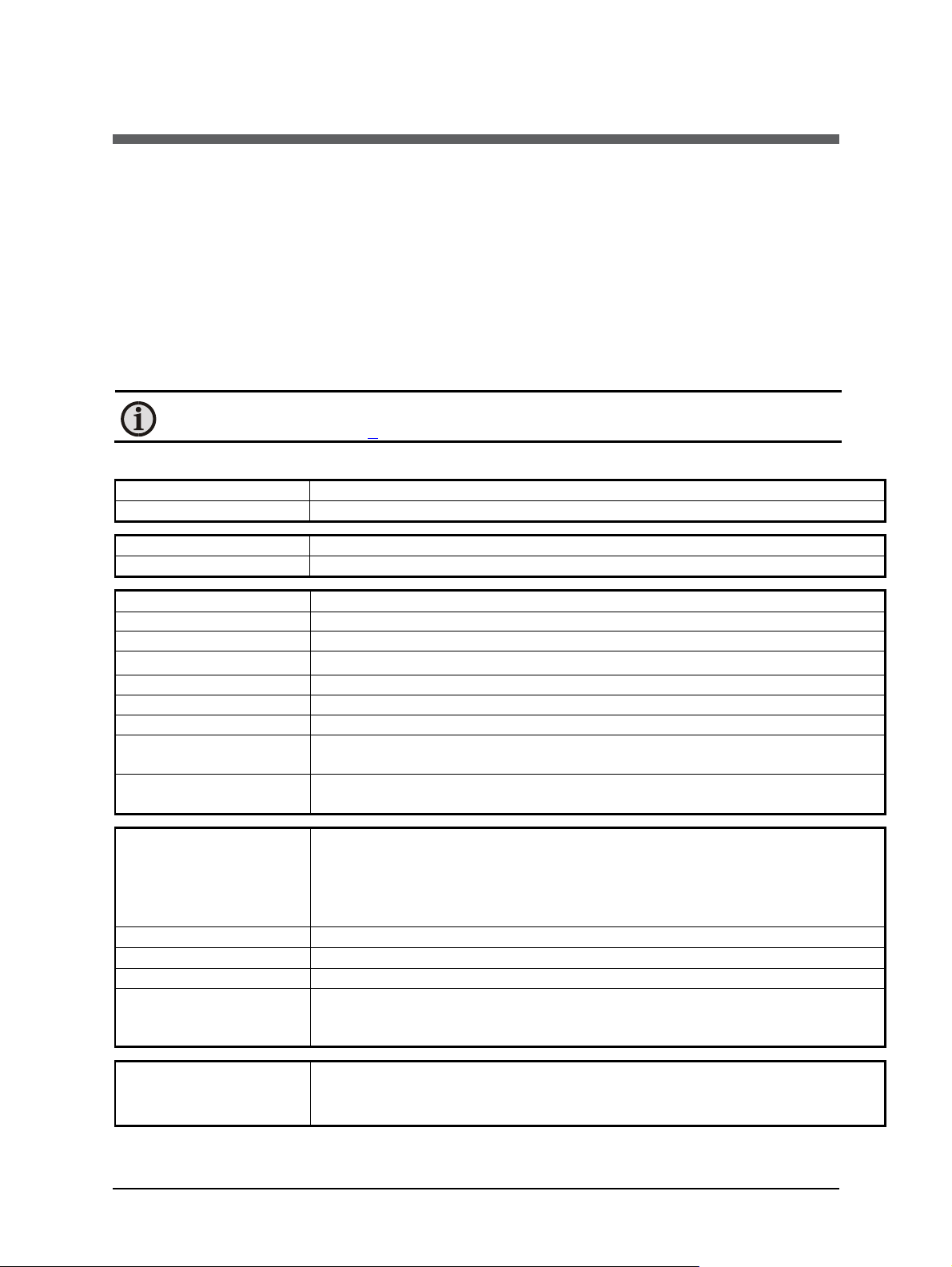
2 Introduction
Temperature range
:
400 ... 11
00
°C
Sub range:
Adjustable to any range within the temperature range. Min. span is 51 °C
Spectral range:
7.8
µm (
FWHM: 0.6
µm)
Optics
:
Silicon
Power supply:
24 V DC
(18
to 30 V DC) nominal, ripple must be less than 0.5 V
Power consumption:
Max. 50 mA
Analog output:
Adjustable,
0 to 20 mA or
4 …
20 mA (linear)
Load:
Max. 500 Ohm at 24 V (Max. 200 Ohm at 18 V)
Digital Interface:
RS485 (half
-
duplex)
RS485 Bus Addres
s:
Set via digital interface
RS485 Baud Rate:
1200 Bd to 115.2 kBd
Resolution:
0.1
°C on interface;
Isolation:
P
ower supply, analog output
,
and digital interface are
electrically
isolated
Parameters:
Adjustable via interface:
InfraWin 4.14s or higher or InfraWin 5
:
Emissivity
:
10.0 to 12
5
.0% adjustable via interface in steps of
0.1%
10.0 to 100.0% adjustable via interface in steps of
0.1
%
Exposure time t
90
:
0.08s;adjustable to
0.5 s; 1 s; 2 s; 5 s; 10 s; 30 s
Maximum
/ minimum
Built
-
in single or double storage. Clearing with
clear
time t
(off;
0.1 s;
0.25 s;
Measurement
0.7% of reading or 3.5 °C, whatever is greater, in °C
2.1 Appropriate use
The IMPAC IN 6/78-L is a stationary pyrometer created for non-contact temperature
measurement of thin glass surfaces with a temperature range between 400 and 1100 °C.
2.2 Scope of delivery
Instrument, PC measurement and evaluation software InfraWin, works certificate, and an
operation manual.
Note: A connection cable is not included with the instrument and has to be ordered
separately (see Chapter 8, Reference numbers).
2.3 Technical Data
< 0.1% of temperature range at the analog output
from each other
Emissivity ε, transmittance t, exposure time t90, 0/4 to 20 mA analog output
range, sub temperature range, automatic clearing of the max. value
storage, external clearing of the max. value storage, clear times of the max.
value storage, address, baud rate, internal temperature, °C / °F
ε
Transmittance t:
value storage:
Uncertainty:
(with ε =1, t90=1 s)
IN 6/78-L Operating Manual Introduction · 9
0.5 s; 1 s; 5 s; 25 s), via interface or automatically with the next measuring
object
(T
= 44 °C)
amb
(Note: the pyrometer must be operate at least 30 min before these values are valid)
clear
Page 10
Repeatability:
(ε =1, t90=1 s)
1
°C
Noise Equivalent
Temperature /
NETD at
t90= 80 ms /
NETD at
t90= 1 s /
Protection class:
IP
65 IEC 60529 (value in mated
condition)
Operation position
:
AnyOpera
ting
temperature
0 to 70
°C
Storage temperature:
-
20 to
80°C
Rel. humidity:
Non-co
ndensing conditions
Weight:
410 g
Housing:
Stainless steel
Connector:
12-pin
connector
Sighting:
CE-label:
Temperature Difference
(NETD) s = 1
(e = 1, Tamb. = 44 °C)
on housing surface:
Note: The calibration / adjustment of the instruments was carried out in accordance
with VDI/VDE directive “Temperature measurement in industry, Radiation
thermometry, Calibration of radiation thermometers”, VDI/VDE 3511, Part 4.4. For
additional details on this directive, see http://info.lumasenseinc.com/calibration or
order the directive from “Beuth Verlag GmbH” in D-10772 Berlin, Germany.
(Note: the pyromet er must be operate at least 30 min before these values are valid)
500
800
°C
0.3
0.3
°C
0.1
0.1
None
According to EN directives about electromagnetic immunity
°C
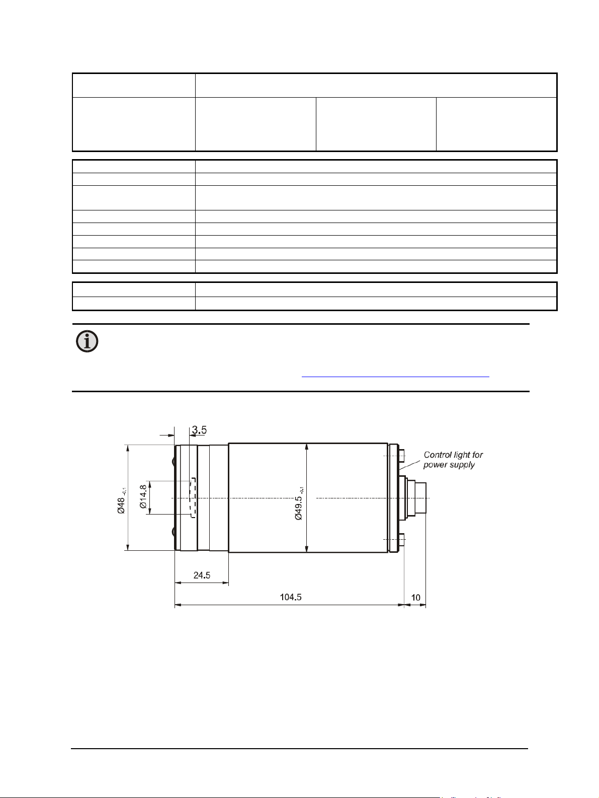
2.3.1 Dimensions
IN 6/78-L Operating Manual Introduction · 10
Page 11
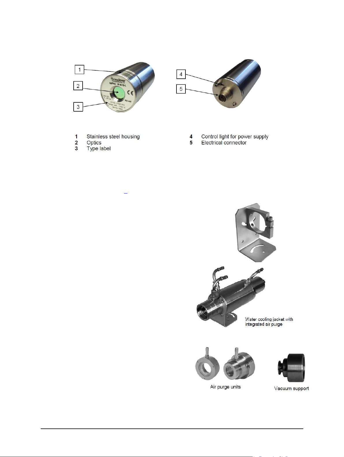
2.4 Physical User Interface
2.5 Accessories (optional)
Numerous accessories guarantee easy installation of the pyrometer. The following overview
shows a selection of suitable accessories. You can find the entire accessory program with all
reference numbers in Chapter 8, Reference numbers).
2.5.1 Mounting
For easy mounting and aligning the pyrometer to the
measured object an adjustable mounting angle is
available.
Mounting
angle
2.5.2 Cooling
The completely covered water cooling jacket made
from stainless steel protects the pyrometer if exposed
to a hot environment. It is designed for ambient
temperatures up to 180 °C.
2.5.3 Miscellaneous
The air purge protects the lens from contamination
with dust and moisture. It has to be supplied with dry
and oil free pressurized air and generates an air
stream shaped like a cone. The pyrometer can be
easily fixed on a vacuum chamber with the KF 16
vacuum support with sighting window.
IN 6/78-L Operating Manual Introduction · 11
Page 12

2.5.4 Displays
For temperature indication of the pyrometer
LumaSense offers several digital displays which can
also be used for remote parametrizing (DA 6000) of
the pyrometer.
IN 6/78-L Operating Manual Introduction · 12
Page 13

3 Controls and Connections
Pin
Color
Indication
K
white
+ 24 V power supply
A
brown
0 V power supply
+ I
analog
output
–
I
analog output
H
gray
ncJpink
ncGred
nc
F
black
B1
(RS485)
C
violet
A1
(RS485)
D
gray/pink
B
2 (RS485)
E
red/blue
A2
(RS485)
Screen only for cable extension,
3.1 Electrical Installation
Series 6 pyrometers are powered by a voltage of 24 V DC nominal (possible range 18 to 30 V DC,
ripple < 0.5 V). It is important to ensure correct polarity when connecting the device to the
power supply.
To meet the electromagnetic requirements (EMV), a shielded connecting cable must be used.
LumaSense offers connecting cables, which are not part of the standard scope of delivery. The
shield of the connecting cable has to be connected only on the pyrometer’s side. If the
connecting cable is extended, the shield of the extension also needs to be extended. The shield
must be open on the power supply side (switch board), to avoid ground loops.
The connecting cable has wires for the power supply, interface, analog output, external laser
switch, and external clear of maximum value storage via contact and 12 pin connector (see
Chapter 8, Reference numbers).The cable includes a short adapter cable with a 9-pin D-SUB
connector. This connector may be used in combination with the RS485 to USB adapter.
Warning: Follow common safety regulations for mains voltage (230 or 115 V AC) and
connecting additional devices operating with this mains voltage (e.g. transformers).
Touching mains voltage can be fatal. A non expert connection and mounting can
cause serious health or material damages.
Only qualified specialists are allowed to connect such devices to the mains voltage.
Once the instrument has been connected to the power supply, it is immediately ready for use.
Although it does not need to be warmed up, it does need to run for approximately 15 to 30
minutes before achieving full accuracy. The instrument can be switched off by interrupting the
power supply or unplugging the electrical connector.
3.1.1 Pin assignment of the male socket on the back of the pyrometer
L green
B yellow
M orange
out
out
don’t connect at the switchboard
IN 6/78-L Operating Manual Controls and Connections · 13
Page 14

3.2 Connecting the pyrometer to a PC
Controller
w
hite
The pyrometer is equipped with a RS485 serial interface. With the RS485, long transmission
distances can be realized and the transmission is, to a large extent, free of problems. The RS485
also allows several pyrometers to be connected in a bus system.
If a RS485 connection is not available at the PC, it can be accomplished using the RS485 to USB
connector. When using a RS485 to USB adapter, make sure that the adapter is fast enough to
receive the pyrometer’s answer to an instruction of the master. Most of the commonly used
adapters are too slow for fast measuring equipment, so it is recommended to use the
RS485 ó USB converter “USB nano“ (ref. no. 3 826 720).
3.2.1 Connecting to RS485 interface / baudrate
Half-duplex mode: A1 and A2 as
well as B1 and B2 are bridged in
the 12-pin round connector of
the connecting cable, to prevent
reflections due to long stubs. It
also safeguards against the
interruption of the RS485 Bus
system should a connecting plug
be pulled out. The master labels
mark the connections on the
RS485 converter. The maximum
transmission rate of the serial
interface in Baud (Bd) is
dependent on the length of the
cable. Values between 1200 and
115000 Bd may be set.
The baud rate has to be reduced by
50% when the transmission distance is doubled (see 4.7 Baud rate). Typical cable length for
19200 Bd is 2 km.
3.2.2 Connecting additional analyzing devices
Additional analyzing instruments, such as a LED digital display instrument, need to be connected
to a power supply and the analog outputs from the pyrometer. Other instruments, like a
controller or printer, can be connected to the display in series as shown below (total load of
resistance max. 500 Ohm).
230V ~
24 V DC
brown
green
°C
yellow
IN 6/78-L Operating Manual Controls and Connections · 14
Power supply
LED digital display
Writer
Page 15

3.3 Sighting
For exact measurement of the object temperature the pyrometer must be aligned correctly onto
the object. Pyrometers without sighting are normally used for measurement of bigger objects
for which exact alignment is not absolutely necessary. These pyrometers can be aligned only
with the thermal method.
3.3.1 Thermal Alignment
When measuring a hot object in front of a cooler background, it is usually sufficient to align the
pyrometer with the hottest spot on the object to achieve the highest temperature reading.
3.4 Optics
The pyrometer is equipped ex works with the following optics. The spot size will enlarge in any
other distance (shorter or longer). Please notice that the measuring object must be at least as
big as the spot size. The following drawing shows the size of the spot in mm in dependence of
the measuring distance. Values between the mentioned data can be calculated by interpolation.
The spot size for measuring distance 0 is the aperture diameter of the optics.
Note: Please note that the optical profiles show nominal dimensions. The spot size
diameter or the focal distance may be slightly different due to lens tolerances.
Note: The InfraWin program includes a Spot size calculator that roughly estimates the
unknown values. The values represented here are for reference purposes.
Spot sizes for intermediate distances that are not shown on the optical profiles, may be
calculated using the following formula:
IN 6/78-L Operating Manual Controls and Connections · 15
Page 16

3.5 Avoiding reading errors caused by faulty assembly
To avoid reading errors, please note the following points when mounting the pyrometer:
1. The diameter of the measuring object cannot be smaller than the pyrometer’s spot size (see
section 3.4, Optics).
2. A source of radiation behind or around the measuring object can influence the result. If the
object is transparent or partly transparent, another material behind the object could
transmit its radiation to the pyrometer as well. In this case, the location of the pyrometer
should be changed, or, if the background radiation remains constant it can be compensated
for by changing the emissivity setting respectively.
3. Please take into account that radiation from other hot surfaces around the measured object
can be reflected by the target and influence the result. If the measured object has a low
emissivity, the temperature measured will be mainly that from the reflected object - not
from the intended measured object itself. To prevent ambient radiation from reaching the
spot area, a mounting tube should be used. The mounting tube should be placed as near as
possible to the measured object so that the tube’s shadow blocks out all the ambient
radiation from the side. Consider whether 4.9 Ambient temperature compensating
applies to the measurement application.
IN 6/78-L Operating Manual Controls and Connections · 16
Page 17

4 Settings / parameter descriptions
Measuring object
Emissivity
(at 7
.8µm)
Glass
98%
Settings:
Before using the pyrometer some basic settings should be taken. The basic settings can
be done via interface and software InfraWin.
Settings via serial interface: The pyrometer is equipped with a serial interface RS485
which can be used for connection to a PC. With the standard software InfraWin (or a self written
communication software) the following settings can be done, to use this functions, emissivity,
transmittance, exposure time, analog output, maximum value storage, minimum value storage,
reading of the instrument’s internal temperature, setting of an address for bus control with
RS485 interface, setting of the baud rate, function for compensating of the off-set of the
ambient temperature). Additionally, InfraWin enables the temperature display and analysis.
4.1 Factory settings
Temperature display (°C / °F) = °C
Emissivity (ε) = 100%
Transmittance (t) = 100%
Exposure time (t90) = 0.08 s (min)
Analog output (out) = 4 ... 20 mA
Baud rate = 19200 Bd
Address = 00
Max./min. value storage = max.
Clear time of max./min. value storage = OFF
Ambient temperature compensation = auto
Wait time tw = 10
4.2 Emissivity ε
For a correct measurement it is necessary to adjust the emissivity. This
emissivity is the relationship between the emission of a real object and the
emission of a black body radiation source (this is an object which absorbs all
incoming rays and has an emissivity of 100%) at the same temperature.
Different materials have different emissivities ranging between 0% and
100% (settings at the pyrometer between 10 and 125%). Additionally the
emissivity is depending on the surface condition of the material, the spectral
range of the pyrometer and the measuring temperature. The emissivity setting of the pyrometer
has to be adjusted accordingly. Typical emissivity value of glass is listed below. The tolerance of
the emissivity value for each material is mainly dependent on the surface conditions. Rough
surfaces have higher emissivities.
Note: The minimum emissivity setting for the pyrometer is 10%.
125%
.
.
.
10%
IN 6/78-L Operating Manual Settings / parameter descriptions · 17
Page 18

One way to determine an accurate emissivity value for a material is to make a comparison
Settings:
Settings:
measurement as follows: If possible, coat a portion of the object with dull black paint or carbon
soot. Paint and carbon soot have high emissivity (95%) and take on the same temperature as the
object. Measure the temperature of the painted area with the emissivity control set to 95%.
Then measure the temperature of an adjacent unpainted area of the object and adjust the
emissivity until the pyrometer displays the same temperature.
4.3 Transmittance t
Measurements through windows slightly attenuates the measuring signal (due to the
transmittance). To obtain correct measuring results, the transmission of the window must be
compensated. Alternatively, the emissivity ε can be adapted.
4.4 Analog output
The analog output has to be selected according to the signal input of the
connected instrument (controller, PLC, etc.).
4.5 Maximum / minimum value storage
If the maximum value storage is switched on, the last highest temperature
value will always be displayed and stored. The minimum value storage saves
the lowest measurement taken during a reading. The storage has to be
cleared at regular intervals and be replaced with a new and actual value.
This feature is particularly useful when fluctuating object temperatures cause
the display or the analog outputs to change too rapidly, or the pyrometer is
not constantly viewing an object to be measured. In addition, it may also be
beneficial to periodically delete and reset the stored maximum values.
The following settings are possible:
Off:
0.1...25 s:
extern:
The max. value storage is switched off and only momentary values are measured.
If any clear time between 0.1 s and 25 s is set (0.1 s, 0.25 s, 0.5 s, 1 s, 5 s, 25 s), the
maximum value is estimated and held in double storage mode. After the
entered time the storage will be deleted.
The external clearing can be activated and used within your own software using
the clear command “lx” (see Chapter 7, Data format UPP). In this case, the
storage operates only in single storage because only a single deletion mechanism
is used.
0 ... 20 mA
4 ... 20 mA
off
0.1 s
0.25 s
0.5 s
1 s
5 s
25 s
extern
auto
auto: The auto mode is used for discontinuous measuring tasks. For example, objects
are transported on a conveyer belt and pass the measuring beam of the
pyrometer for only a few seconds. In this case, the maximum value for each object
has to be indicated. In this mode the maximum value is stored until a new hot
object appears in the measuring beam. The temperature which has to be
recognized as hot is defined by the low limit of the adjusted sub range. The
stored maximum value will be deleted when the temperature of the new hot
object exceeds the low limit from of the sub range by 1% or at least 2 °C. If a
lower limit is not entered, the maximum value storage will be deleted whenever
the lower level of the full measuring range has been exceeded.
Operation
note:
IN 6/78-L Operating Manual Settings / parameter descriptions · 18
Depending upon which setting is selected, the maximum value storage will either
work in single storage mode or in double storage mode:
Page 19

Single storage: The single storage mode is used when you want to reset the
Settings:
Settings:
stored value using your own software with the clear command “lx”. This
mode allows a new value to be established after each impulse from the reset
signal.
Double storage: The double storage mode is automatically selected when
entering the reset intervals using the PC interface. This mode utilizes two
memories in which the highest measured value is held and is deleted
alternately in the set time interval (clear time). The other memory retains the
maximum value throughout the next time interval. Disadvantages of
fluctuations in the display with the clock frequency are thereby eliminated.
Note: In the command structure, the maximum storage comes after the exposure
time. This results in:
· clear time £ the adjusted response time is useless
· clear times must be at least 3 times longer than the response time
· only maxima with full maximum value can be recorded, which appear at
least 3 times longer than the response time.
4.6 Subrange
You have the opportunity to choose a subrange (minimum span 51 °C) within the basic
measuring range of the pyrometer. This subrange corresponds to the analog output. Reduction
of the temperature range increases the accuracy of the analog output.
Also when setting the subrange, it is possible to fulfill the requirements of the “auto” clear
mode of the maximum value storage (see 4.5 Maximum/minimum value storage).
4.7 Baud Rate
The highest permissible transmission rate of the serial interface in Baud (Bd)
is dependent on the length of the cable. A standard cable length with RS485
is 2 km at 19200 baud. The baud rate is reduced by 50% if the transmission
distance is doubled.
1200 bd
.
.
.
115000 bd
4.8 Address
When connecting several pyrometers to one serial interface with RS485, it is
necessary for each instrument to have its own device address for
communication purposes. First, it is necessary to connect each instrument
separately to give it an address. After that, all instruments can be connected
and addressed individually.
Note: Only via own communication program with interface command (not
possible with InfraWin, because InfraWin automatically detects a connected
pyrometer): If parameters should be changed simultaneously on all pyrometers, the
global Address 98 can be used. This allows you to program all pyrometers at the
same time, regardless of the addresses that have already been assigned. If the address
of a pyrometer is unknown, it is possible to communicate with it using the global
Address 99 (connect only one pyrometer).
00
97
.
.
.
4.9 Ambient temperature compensation
Each object has an emissivity e (maximum 100%). If the measured object is not transparent and
has an emissivity of less than 100% (as in most cases), a portion of the resulting radiation will be
IN 6/78-L Operating Manual Settings / parameter descriptions · 19
Page 20

reflected. For bright, smooth surfaces, such as mirrors, the reflected radiation is more focused;
Settings:
on rough, harsh surfaces it is diffuse. The rate of diffuse reflection is, in this case (100% - e).
If the measured object’s temperature is the same as the ambient temperature (this is most often
the case), you only need to set the emissivity on the pyrometer (when using the InfraWin
program the off-set compensation for the ambient temperature must be in “auto“. If the object
to be measured is in an oven, where the temperature is higher than the ambient temperature, a
portion of the radiation, corresponding to the rate of diffuse reflection, will be “reflected“ by
the measured object to the pyrometer, resulting in an inaccurate reading (the reading will be
too high due to the oven temperature).
In this case, it makes sense to activate the off-set compensation for the ambient temperature (in
the parameter window of the InfraWin program: Compensating for the off-set of the ambient
temperature switched to “man.“ (= manual) and then enter the ambient temperature value (in
this case, the oven temperature) in the corresponding field. The program also makes a
compensation calculation in order to display the correct temperature.
Be aware that the accuracy of such a correction is highly dependent on accuracy of the emissivity
value that was set. The off-set compensation for the ambient temperature uses the rate of
diffuse reflection when performing its calculation. If you alter the emissivity (e), you are also
altering the rate of diffuse reflection (100% – e) and in turn, the displayed temperature. The
following observation shows how a faulty emissivity reading in conjunction with the
compensation for the ambient temperature affects results:
Entry of e = 91% instead of 92% indicates:
A relative change in emissivity of 1.1 %.
Likewise the assumed rate of reflection changes from 8 % to 9 %.
This results in a relative increase in reflection of 12.5 %.
This change also impacts the displayed result, thereby causing a fairly inaccurate compensation
calculation. For hot environments, this calculation will probably serve as a much more accurate
assessment than the standard calculation, which assumes that the ambient temperature is the
same as that of the object measured.
4.10 Wait time t
Using a pyrometer with RS485 it is possible that the connection is not fast
enough to receive the pyrometer’s answer to an instruction of the master. In
this case a wait time can be set to slow down the data transfer (e.g.: tw = 02
at a baud rate 9600 means await time of 2/9600 sec).
w
00 Bit
.
.
.
99 Bit
Note: The pyrometer enters a waiting period after certain commands and may not
respond right away because some commands have an internal processing time of up
to 3 ms.
4.11 Internal Temperature of the Pyrometer
The internal temperature of the pyrometer can be read via interface. It is a few degrees above
the ambient temperature due to the heat generated by the pyrometer electronics.
IN 6/78-L Operating Manual Settings / parameter descriptions · 20
Page 21

5 Software InfraWin
The operating and analyzing InfraWin software is included with delivery of the pyrometer. In
addition to allowing you to make parameter adjustments, the InfraWin software also provides
temperature indication, data logging, and measurement analysis features.
This section gives an overview about the functions of the software. It also provides a description
of the individual icons found in the program's help menu. Click on the F1 button after loading
InfraWin or click on the ? in the menu bar.
The following descriptions refer to software InfraWin version 5.0. The latest version is available
for free as download from the homepage www.lumasenseinc.com.
5.1 Connecting the pyrometer to a PC
The program InfraWin can operate up to two devices. Two devices using RS485 may be operated
simultaneously by the same interface, if two different addresses have been properly entered
(see section 4.8 Address for more information).
5.2 Installation
To install the InfraWin software, select setup.exe from the InfraWin-CD or from the downloaded
and unpacked zip file from the internet and then follow the installation instructions.
5.3 Program start
The first time you load InfraWin 5, you will be prompted to select a default language. The
InfraWin software is available in German, English, Spanish, French, Portuguese, and Chinese.
Once installed, click Language/Languages if you would like to select another language.
On the start page, the screen shows the following start menu icons.
Opens a saved file
Storage of measured values for further processing
Starts measurement for the selected device
Setting of the parameters of the instruments
Time interval between two measurements
Listing of measured or stored values in tabular form
Processing of measured (stored) readings in graph form
Processing of measured (stored) readings in a text file
Calculation of spot sizes in various measuring distances
Only if available: controls the programmable controller PI 6000
Search I/O module
IN 6/78-L Operating Manual Software InfraWin · 21
Page 22

5.4 Basic settings
All preset values for the
device can be displayed
and modified, if necessary under
the Devices/Parameters window.
This window contains the
parameter settings described in
Chapter 4, Parameters.
Changing an existing pyrometer
setting can be accomplished by
typing a value in an input box or
by selecting a preset value from
the list field. Choose the correct
settings for your application
from the displayed options.
Once a value is changed, it is
transferred to the pyrometer
immediately.
Clicking on the Test icon will
open a window that allows you
to directly communicate with the
pyrometer using the UPP
(Universal Pyrometer Protocol)
Data Format commands. See
Chapter 7 for information on
working with the UPP Data
Format commands.
After entering an interface
command (00 is the adjusted
address ex works, ms is the
command reading
temperature value) and
clicking on Send, the window
shown to the right will be
opened.
This window already shows the answer of the pyrometer in 1/10°. The actual temperature
reading is 399.0 °C.
Len indicates the length of the answered data string, incl. Carriage Return (Chr(13)).
In the lower part of the window the connection with the preset baud rate can be checked. Here
the command was sent 100 times with 19200 baud. It has taken 0.937 seconds without
transmission errors.
IN 6/78-L Operating Manual Software InfraWin · 22
Page 23

Emi: AutoFind: If the true temperature of the measured object is known, you can calculate the
emissivity of the measured object using the Emi: AutoFind function:
A measured temperature is displayed with the
current set emissivity (in this example 100%) (here:
416.1 °C).
If you press Emi: Autofind a window will open
which allows you to enter the "true" temperature
(here 430 °C).
Once the temperature entry has been entered and
confirmed with Calculate, InfraWin will then
calculate the emissivity which occurs with the new
temperature (here 97.3%). This is displayed
immediately and can be used for further
temperature measurement.
5.5 Measurement online trend
The Measurement online
trend window displays:
· temperature as graphical diagram
· internal temperature of the instrument
· current temperature
· the quantity of the measured values
and file size of the current
measurement.
The example shows a sample reading over the
period of approximately 15 seconds with a
temperature range between 400 and 800 °C. The final temperature (at the end of the reading) is
431 °C.
The Mark Zone button allows you to color mark a temperature range for easier recognition.
The Threshold button allows you to set a temperature value as a baseline to prevent recording
values above or below the baseline temperature. This allows you to keep the output file size
small.
The Scaling Trend button allows you to scale temperature trend view.
IN 6/78-L Operating Manual Software InfraWin · 23
Page 24

Note: The measuring values of “measurement online trend” are automatically saved
as "standard.i12". Should you need to edit the data later, you need to save the file as
another .i12-file because old values are over-written when a new measurement is
taken.
Files from older program versions (.i10-files) can be opened and saved as .i12.
5.6 Listing (analyzing)
For analyzing
the measured
values in this field, all measured
data appears in a numeric list.
The column between time and
temperature provides a time
resolution of milliseconds. The
value specifies the time in seconds
after midnight (0:00 h). The amount
of data depends on the frequency
that readings were taken (settings
at 10.9 PC sampling rates). As the
amount of data increases, so does
the amount of storage space
required to save it. In order to save room, all .i12 data files are stored by a binary code.
5.7 Output .TXT file (analyzing)
The same file as under Output listing may be converted into a text file and
can be easily opened, for example with EXCEL. With the standard import
settings, EXCEL automatically formats the columns accordingly (with tabs as separators).
5.8 Trend output (analyzing)
The graph’s curve depicts the
temperature change over time
within the specified temperature
range.
Additionally, other information
appears in this window; such as
recorded time (x-axis) and
temperature in degrees (y-axis) as
well as the time and temperature
at the vertical cursor line which can
be dragged with the mouse.
Selecting the Trend output initially
causes all the saved data to be
displayed.
If the data exceeds an amount that can be reasonably represented, you may “Zoom“ in on a
partial segment using the mouse (such as the segment represented in the example). Under
“Total” you can return to the representation of the entire curve.
IN 6/78-L Operating Manual Software InfraWin · 24
Page 25

Note: The last reading is saved in the standard.i12 file and automatically appears in
this form upon opening Listing or Trend output.
Selecting file open with another file, the previous file will be overwritten and replaced by the standard.i12 file.
5.9 PC sampling rate (time interval between two
measurements)
This function sets a time interval. After
each interval, one measured value is
stored on the PC. Longer time intervals will result in
creating smaller stored file sizes. This function is mainly
used for long term measurements
5.10 Spot size calculator
The InfraWin Spot Size Calculator
calculates the data for the nonfocused regions. To calculate data, enter the values
of aperture D, focused measurement distance a,
and focused measuring field diameter M as found
in the documentation relating to the optics
supplied with your specific pyrometer.
After entering the aperture and the main spot size,
the input of interim values calculates spot sizes in
different measuring distances of the fixed optics.
5.11 Search I/O Module
The I/O Module allows
accessories to connect to
the software and is used to trigger
measurement externally or to send a signal
(like a relay) under certain conditions.
IN 6/78-L Operating Manual Software InfraWin · 25
Page 26

To ensure consistent document formatting, this page was intentionally left blank.
IN 6/78-L Operating Manual Software InfraWin · 26
Page 27

6 Maintenance
6.1 Safety
Attention during pyrometer services: Should the pyrometer be integrated in a
running machine process, the machine should be switched off and secured against
restart before servicing the pyrometer
6.2 Service
The pyrometer does not have any parts which require regular service, only the lens has to be
kept clean. The lens can be cleaned with a soft cloth in combination with alcohol (do not use
acid solutions or dilution). Also standard cloths for cleaning glasses or photo objectives can be
used.
IN 6/78-L Operating Manual Maintenance · 27
Page 28

To ensure consistent document formatting, this page was intentionally left blank.
IN 6/78-L Operating Manual Maintenance · 28
Page 29

7 Data format UPP (Universal Pyrometer
Description
Command
Parameters
Readin
g
AAms
Output: YYYYY
Emissivity:
AAemXXXX
XXXX = (0
10
0 ... 125
0%) (decimal)
Transmittance
:
AAetXXXX
XXXX = (0
10
0 ... 1000%
) (de
c
imal)
Exposure time t
:AAezX
X = 0 ... 6 (decimal)
Analog output
*:AAasX
X = 0 or 1
0 = 0
…
20 mA;
1 = 4
…
20 mA
Clear time of
AAlzX
X = 0 ... 8
(decimal)
External clearing:
AAlx
Delete maximum storage value (only active wit
h lz=7)
Changing °C / °F
*:
AAfhX
X = 0;1 (decimal)
Protocol)
Via interface and suitable communication software or via Test function of the InfraWin
software (see Section 5.4 Basic settings) commands can be exchanged directly with the
pyrometer.
The data exchange occurs in ASCII format with the following transmission parameters:
The data format is: 8 data bits, 1 stop bit, even parity (8,1,e).
The device responds to the entry of a command with: output (e.g. the measuring value) + CR
(Carriage Return, ASCII 13), to pure entry commands with ok + CR.
Every command starts with the 2-digit device address AA (e.g. "00"). This is followed by 2 small
command letters (e.g. "em" for level of emissivity e), finished with CR.
This is followed, if necessary for that command, by the ASCII parameter "X". If this parameter
"X" is omitted, then the device resets with the current parameter.
A ? after the small command letters answers with the respective settings (only at setting
commands, not at enquiry commands).
Example: Entry: “00em“ + <CR>
The emissivity setting (e) of the device with the address 00 is returned.
Answer: “0970“ + <CR> means Emissivity = 0.97 or 97.0%
measuring value:
90
maximum /
minimum value
storage:
5-digit decimal, in 1/10°C or. °F
88880 = temp. overflow
02563 = 256.3 °C or °F
0 = intrinsic time constant of the device
1 = 0.5 s 3 = 2 s 5 = 10 s
2 = 1 s 4 = 5 s 6 = 30 s
0 = Maximum value storage off
1 = 0.10 s 4 = 1.00 s 7 = externally deleted
2 = 0.25 s 5 = 5.00 s 8 = automatically deleted
3 = 0.50 s 6 = 25.00 s
0 = Output Celsius
1 = Output Fahrenheit
IN 6/78-L Operating Manual Data format UPP (Universal Pyrometer Protocol) · 29
Page 30

Description
Command
Parameters
Reading basic
temperature range:
AAmb
Output: YYYY
ZZZZ
(hex 8
-
digit, °C or °F)
Reading
AAme
as with mb
Repeatedly reading
XXX = 000 to 999
Error status:
AAfs
Output 1 Byte hex
Reading
AApa
Output 11
-
digit decimal:
Device address
*:AAgaXX
XX: Device address decimal
Baud rate:
AAbrX
X = 0 to 6 or 8 (dec.)
Internal
pyrometer
AAgt
Output: XXX (dec
. 000 ... 099
°C, 032 ... 210
°F
)
Max. internal
AAtm
Output: XXX (dec. 000 ... 099
°C, 032 ... 210
°F
)
Reset
*:AAre
Reset devic e
Command delay:
AAtwXX
XX = 00 to 99 relative delay value
Reading ambient
AAut
Output:
stored value, 4
-
digit hex
Entering ambient
AAutXXXX
XXXX = value of ambient temperature, 4
-
digit, hex
M
arginal values for
AAut?
Output: marginal values for the entry, 2 x 4
-
digit, hex
Reading
AAmi
Output: 0 or 1
Setting of
AAmiX
X = desired setting
temperature sub
range:
measuring values:
YYYY = beginning of temp. range
ZZZZ = end of temp. range
AAmsXXX
XXX = No. of measuring values
Bit 0 = 1: EEPROM error
Bit 1 = 1: Watch dog Reset
Bit 2 = 1: Under voltage reset
parameters:
temperature:
pyrometer
temperature:
temperature:
Digit 1 and 2 (10 to 99 or 00): emissivity
Digit 3 (0 to 6): t90 (exposure time)
Digit 4 (0 to 8): tCL (storage delete mode)
Digit 5 (0 to 1): analog output
Digits 6 and 7 (00 to 99): temperature
Digits 8 and 9 (00 to 97): address
Digit 10 (0 to 6 or 8): baud rate
Digit 11 always 0
00 to 97 variable device addresses
98 = global address without response (only setting commands!)
99 = global address with response
0: 1200 Bd 3: 9600 Bd 6: 57600 Bd
1: 2400 Bd 4: 19200 Bd 7: not allowed
2: 4800 Bd 5: 38400 Bd 8: 115200 Bd
e.g. 0258 corresponds to 600 degrees
temperature:
ambient
temperature:
maximum/minimum
values:
maximum/minimum
values:
IN 6/78-L Operating Manual Data format UPP (Universal Pyrometer Protocol) · 30
XXXX e.g. FFEC corresponds to –20 degrees
- 99dez = FF9Dhex means: automatic, no manual
compensation
e.g. FF9D0384 corresponds to -99 to 900 degrees
0 = maximum value, 1 = minimum value
0 = maximum value, 1 = minimum value
Page 31

Description
Command
Parameters
Reading marginal
values:
AAmi?
Output: marginal value for entry, always 01
Device type:
AAna
Output:
“IN 6/78
-L”(16 ASCII
-
characters)
Se
rial number:
AAsn
Output: XXXXX
(5-digit decimal)
Reference number:
AAbn
Output:
XXXXXX
(6-digit hex)
Device
model/
AAve
Output: XXYYZZ (6
-
digit decimal)
Software version:
XX = 79 (IN 6/78-L)
YY = month of the software version
ZZ = year of the software version
Note: the lett er “l” means the lower case letter of “L”.
* After entering these commands the device carries out an automatic reset. The device needs approx. 150 ms before it is
ready to use and work with the changed settings.
Additional instructions for the RS485 interface:
Requirements to the master system during half-duplex operation:
1. After an inquiry, the bus should be switched into a transmission time of 3 bits
(some older interfaces are not fast enough for this).
2. The pyrometer's response will follow after 5 ms at latest.
3. If there is no response, there is a parity or syntax error and the inquiry has to be
repeated.
IN 6/78-L Operating Manual Data format UPP (Universal Pyrometer Protocol) · 31
Page 32

To ensure consistent document formatting, this page was intentionally left blank.
IN 6/78-L Operating Manual Data format UPP (Universal Pyrometer Protocol) · 32
Page 33

8 Reference numbers
Type
Temperature Range
Reference Number
IN 6/78
-L400 ... 11
00°C3 906 010
8.1 Reference numbers instrument
Ordering note:
A connection cable is not included in scope of delivery and has o be ordered separately.
8.2 Reference numbers accessories
3 820 330 Connection cable, length 5 m, straight connector, 12 pin
3 820 500 Connection cable, length 10 m, straight connector, 12 pin
3 820 510 Connection cable, length 15 m, straight connector, 12 pin
3 820 810 Connection cable, length 20 m, straight connector, 12 pin
3 820 820 Connection cable, length 25 m, straight connector, 12 pin
3 820 520 Connection cable, length 30 m, straight connector, 12 pin
3 820 740 Connection cable, length 5 m, temperature resistant up to 200 °C,
straight connector, 12 pin
3 820 340 Connection cable, length 5 m, 90° connector, 12-pin
3 820 530 Connection cable, length 10 m, 90° connector, 12-pin
3 820 540 Connection cable, length 15 m, 90° connector, 12-pin
3 820 830 Connection cable, length 20 m, 90° connector, 12-pin
3 820 840 Connection cable, length 25 m, 90° connector, 12-pin
3 820 550 Connection cable, length 30 m, 90° connector, 12-pin
3 852 290 Power supply NG DC for carrier rail mounting housing
(100 ... 240 V AC, 50 ... 60 Hz Þ 24 V DC, 1 A)
3 852 540 Power supply NG 0D (85...265 V AC Þ 24 V DC, 600 mA)
3 852 550 Power supply NG 2D carrier rail mounting housing
(85 ... 265 V AC Þ 24 V DC, 600 mA, with 2 limit switches)
3 890 640 DA 4000-N: LED digital display for switchboard assembling
3 890 650 DA 4000: as DA 4000-N, additionally with 2 limit switches
3 890 570 DA 6000-N RS485
3 890 530 DA 6000 with RS485
3 826 510 PI 6000: PID programmable controller, very fast, for digital IMPAC pyrometers
3 826 720 Converter RS485 Û USB (half duplex)
3 852 440 Protocol converter RS485 (switchable) Û Profibus-DP for 1 instrument
3 852 460 Protocol converter RS485 Û Profibus-DP for 32 instruments
5 837 410 Cooling jacket for IN 6/78-L
3 834 210 Adjustable mounting support
3 385 160 Air purge unit
3 835 440 Air purge unit, stainless steel
3 846 100 Mounting tube
3 846 120 Flange tube
IN 6/78-L Operating Manual Reference numbers · 33
Page 34

To ensure consistent document formatting, this page was intentionally left blank.
IN 6/78-L Operating Manual Reference numbers · 34
Page 35

9 Troubleshooting
Before sending the pyrometer for repair, try to find the error and to solve the problem with the
help of the following list.
Temperature indication too low
· Incorrect alignment of the pyrometer with the object
Þ Realign to achieve the maximum temperature signal(see 3.3)
· Measuring object smaller than spot size
Þ check measuring distance, smallest spot size is at nominal measuring distance (see 3.4)
· Measuring object is not always in the measuring spot of the pyrometer
Þ Use maximum value storage (see 4.5)
· Emissivity set too high
Þ Set lower correct emissivity corresponding to the material (see 4.2)
· Lens contaminated
Þ Clean lens carefully (see 6.2)
Temperature indication too high
· Emissivity set too low
Þ Set lower correct emissivity corresponding to the material (see 4.2)
· The measurement is influenced by reflections of hot machine parts
Þ Use mechanical construction to avoid the influence of the interfering radiation
Measuring errors
· Indicated temperature is decreasing during the use of the pyrometer, contamination of the
lens
Þ Clean lens. Recommendation: use of air purge (see 3.3)
· Indicated temperature is decreasing during the use of the pyrometer, although the air purge
unit is used. Probably compressed air is not clean or air failed
Þ Clean the lens and use clean, dry and oil free compressed air
· Air contamination in the sighting path between pyrometer and object
Þ Change position of the pyrometer with a clean sighting path (if necessary use a ratio
pyrometer)
· RF-interferences
Þ Correct the connection of the cable shield (see 3.1)
· Instrument overheated
Þ Use cooling jacket with air or water cooling (see 2.5)
· Temperature Indication is fluctuating, probably caused by changing emissivity
Þ Wrong pyrometer type, use of ratio pyrometer recommended
IN 6/78-L Operating Manual Troubleshooting · 35
Page 36

To ensure consistent document formatting, this page was intentionally left blank.
IN 6/78-L Operating Manual Troubleshooting · 36
Page 37

Index
A
Accessories 11, 33
Cooling 11
Displays 12
Miscellaneous 11
Mounting 11
Address 19
Ambient temperature compensation 19
Analog output 18
Analyzing devices, additional 14
Appropriate use 9
B
Basic settings 22
Baud Rate 19
Baudrate 14
C
Clear time of the maximum / minimum
value storage 18
Connecting the pyrometer to a PC 14, 21
Connecting to RS485 interface / baudrate 14
Connection cable 9
Connections 13
D
Data format UPP 29
Dimensions 10
Disposal 8
Double Storage 18
E
Electrical Installation 13
Electromagnetic requirements 13
Emi: AutoFind 23
Emissivity ε 17
F
Factory settings 17
I
Installation 21
Installation, electrical 13
Internal Temperature 20
L
Legend 5
Listing (analyzing) 24
M
Maintenance 27
O
Optics 15
P
Packaging 6
Parameter descriptions 17
Physical User Interface 11
Pin assignment of the male socket 13
Program start 21
R
Reading errors 16
Reference numbers 33
Repair 7
RS485 interface 14
S
Safety 5, 27
Scope of delivery 9
Service 27
Service Request 7
Settings 17
Sighting 15
Single Storage 18
Software InfraWin 21
Spot size calculator 25
Storage 6
Subrange 19
Support 7
I/O Module 25
IN 6/78-L Operating Manual IndexIndexIndexIndex · 37
Page 38

T
Technical data 9
Thermal Alignment 15
Time interval 25
transmittance 18
Transmittance t 18
Transport, packaging, storage 6
Trouble shooting 35
TXT file 24
U
Unpacking the Instrument 6
UPP data format 29
W
Wait time 20
Warranty 6
IN 6/78-L Operating Manual Index · 38
 Loading...