


M137
M 2103
Xelos M137 VT
Art.-Nr. 61469
Xelos M155 VT
Art.-Nr. 61473
Serviceanleitung.
Service Manual.
Xelos M137 VT 61469
230-90364.994

Allgemeiner Teil / General Section M 2103
1 - 2 LOEWE.-Service
GB
Table of Contents
Page
General Section .................................. 1-2…1-16
General Notes .............................................................................. 1-3
Note on electrostatic shielding ..................................................... 1-5
Safety Precautions ....................................................................... 1-5
Leakage current cold check ......................................................... 1-5
Leakage current hot check........................................................... 1-5
X-Radiation warning ..................................................................... 1-5
Measuring high voltage ................................................................ 1-5
Module List ................................................................................... 1-6
Technical Data ............................................................................. 1-7
Circuit Diagram Symbols ............................................................. 1-8
Hints to the Oscillograms ........................................................... 1-12
Hints to Components ................................................................. 1-12
Service and Special Functions................................................... 1-15
Adjustment ........................................... 2-3…2-4
Layout of the PCBs
and Circuit Diagrams ......................... 3-1…3-35
Chassis Board .............................................................................. 3-1
Oscillograms Chassis .................................................................. 3-7
Chassis Board Enlarged .............................................................. 3-9
Page
Circuit Diagram Mains Section................................................... 3-13
Circuit Diagram Deflection Section ............................................ 3-15
Circuit Diagram Processor Section ............................................ 3-17
Circuit Diagram Tuner Section ................................................... 3-19
Circuit Diagram Video ................................................................ 3-21
Circuit Diagram Audio ................................................................ 3-23
CRT Panel ................................................................................. 3-25
SAT Module ............................................................................... 3-27
Processor Board ........................................................................ 3-33
Spare Parts Lists ..................................4-1... 4-8
Loewe Service .................................... 4-9…4-10
Loewe-Establishments ................................................................. 4-9
Loewe-Service and Logistics ....................................................... 4-9
Loewe Service Europe ............................................................... 4-10
Loewe Service Overseas ........................................................... 4-10
D
Inhaltsverzeichnis
Seite
Allgemeiner Teil ................................. 1-2... 1-14
Allgemeine Hinweise.................................................................... 1-3
Hinweise zum Schutz gegen Elektrostatik ................................... 1-4
Sicherheitsvorkehrungen ............................................................. 1-4
Messung des Isolationswiderstandes im abgeschalteten Zustand ...... 1-4
Messung des Kriechstromes im eingeschalteten Zustand ................. 1-4
Achtung, Röntgenstrahlung ............................................................. 1-4
Messung der Hochspannung ...........................................................1-4
Modulübersicht ............................................................................. 1-6
Technische Daten ........................................................................ 1-7
Schaltplansymbole ....................................................................... 1-8
Hinweise zu den Oszillogrammen .............................................. 1-12
Hinweise zu den Bauteilen......................................................... 1-12
Service- und Sonderfunktionen .................................................. 1-13
Abgleich ................................................ 2-1... 2-2
Platinenabbildungen
und Schaltpläne ................................. 3-1... 3-35
Chassisplatte ............................................................................... 3-1
Oszillogramme Chassis ............................................................... 3-7
Chassisplatte vergrößert .............................................................. 3-9
Seite
Teilschaltplan Netzteil ................................................................ 3-13
Teilschaltplan Ablenkung ........................................................... 3-15
Teilschaltplan Prozessor ............................................................ 3-17
Teilschaltplan Tuner ................................................................... 3-19
Teilschaltplan Video ................................................................... 3-21
Teilschaltplan Audio ................................................................... 3-23
Bildrohrplatte .............................................................................. 3-25
SAT-Baustein ............................................................................. 3-27
Prozessorplatte .......................................................................... 3-33
Ersatzteillisten ......................................4-1... 4-8
Loewe Service .................................... 4-9…4-10
Loewe-Vertragswerkstätten ......................................................... 4-9
Loewe-Service und Logistik ......................................................... 4-9
Loewe Service Europa ............................................................... 4-10
Loewe Service Übersee ............................................................. 4-10
M 2103 Allgemeiner Teil / General Section
LOEWE.-Service 1 - 3
Allgemeine Hinweise
Vor dem Öffnen des Gehäuses zuerst den Netzstecker ziehen!
Leitungsverlegung
Bevor Sie die Leitungen und insbesondere die Masseleitungen lösen,
muss die Leitungsverlegung zu den einzelnen Baugruppen wie z.B.
Chassis, Netzschalterplatte, Bedieneinheit, Bildrohrplatte, Ablenk-
einheit, Lautsprecher usw. beachtet werden.
Nach erfolgter Reparatur ist es notwendig, die Leitungsführung wieder
in den werkseitigen Zustand zu versetzen um evtl. spätere Ausfälle
oder Störungen zu vermeiden.
Netzkabel
Diese Geräte dürfen nur mit dem Original-Netzanschlusskabel mit
integrierter Entstördrossel betrieben werden. Dieses Netzkabel ver-
hindert Störungen aus dem Netz und ist Bestandteil der Geräte-
zulassung. Im Ersatzfall bestellen Sie bitte ausschließlich das Netz-
kabel laut Ersatzteilliste.
General Notes
Before opening the cabinet disconnect the mains plug!
Wiring
Before disconnecting any leads and especially the earth connecting
leads observe the way they are routed to the individual assemblies like
the chassis, mains switch panel, keyboard control panel, picture tube
panel, deflection unit, loudspeaker and so on.
On completion of the repairs the leads must be laid out as originally
fitted at the factory to avoid later failures or disturbances.
Mains cable
The TV receiver must only be operated with an original mains connecting
cable with an interference suppressor choke integrated in the mains
plug.This mains cable prevents interference from the mains supply and
is part of the product approval. For replacement please order exclusively
the mains connecting cable specified in the spare parts list.
Typenschild des Gerätes
Zusätzlich zum Gerätetyp und der Chassisbezeichnung enthält das
Gerätetypenschild eine sogenannte "Version number" z.B. VNA. Die-
se Kennzeichnung gibt Aufschluß über den technischen/mechani-
schen Fertigungsstand.
Für die Bestellung von Ersatzteilen sind deshalb folgende Angaben
unbedingt erforderlich:
- Gerätetype (z.B. "Xelos M155 VT")
- Version number (z.B. "VNM")
- Materialnummer des Ersatzteils
Type Label on the set
In addition to the type of the TV set and the designation of the chassis,
a so-called "Version number", e.g. VNA, is printed on the type label.
This identification gives information on the technical/mechanical state
of production.
Do not fail to give the following particulars when ordering spare parts:
- type of TV set (e.g. "Xelos M155 VT")
- version number (e.g. "VNM")
- part number spare part
Xelos M155VT
ART. NR. 61473
220-240V~ 50/60HZ 60W
By 646/98/Rö
BESCHLEUNIGUNGSSPANNUNG MAX. 31KV, 1.0MA.
QUESTO APPARECCHIO É COSTRUITO CONFORME
ARTICOLO 2 DEL D.M.
28.08.95 N. 548
TENSIONE D ACCELERAZIONE MAX. 31kV, 1.0mA.
MADE IN EUROPE
31kV
V98200
VNM
Gerätetype
Type of product
Versionsnummer
Version number
Bestellnummer ohne Farbkennzeichnung
Order number without colour code
Allgemeiner Teil / General Section M 2103
1 - 4 LOEWE.-Service
Hinweise zum Schutz gegen Elektrostatik
1. Elektrostatisch gesicherte MOS-Arbeitsplätze
Der Umgang mit gegen Elektrostatik empfindlichen Bauteilen muss
an einem elektrostatisch gesicherten MOS-Arbeitsplatz erfolgen.
Ein elektrostatisch gesicherter MOS-Arbeitsplatz erdet über
Entladungswiderstände sämtliche leitende Materialien einschließ-
lich der Person. Nichtleiter werden durch Luftionisation entladen.
Die Integration von Lötkolben und Messgeräten in den gesicherten
MOS-Arbeitsplatz ist nur mit Trenntrafo in jedem der verwendeten
Geräte möglich. Die Messgeräte-Massen werden ebenfalls mit
Entladungswiderständen geerdet.
2. Gesicherte Verpackung durch leitfähige Materialien
Zum Schutz gegen Elektrostatik werden elektrisch leitende Kunst-
stoffe für Verpackung und Transportmittel verwendet. Leitende
Kunststoffe gibt es als schwarze oder transparente Schutzbeutel,
Schaumstoff, Folien und als Behälter.
Empfindliche Bauteile dürfen nur am gesicherten MOS-Arbeitsplatz
aus der Verpackung entfernt bzw. verpackt werden.
Sicherheitsvorkehrungen
Allgemeine Richtlinien
1. Diese Geräte sind über einen Wandler-Trafo vom Netz getrennt. Bei
Service-Arbeiten an der Primärseite dieses Trafos ist ein Trenn-
transformator erforderlich.
2. Bei der Durchführung von Servicearbeiten dürfen die ursprüngli-
chen Kabelanschlüsse nicht vertauscht werden. Dies gilt insbeson-
dere für die Anschlüsse im Hochspannungsteil. Hat sich ein Kurz-
schluss ereignet, dann sind alle Teile, an denen Spuren von Über-
hitzung sichtbar sind, auszuwechseln.
3. Da verschiedene Teile dieser Geräte Sicherheitsfunktionen aufwei-
sen nur Original-Hersteller-Ersatzteile verwenden.
Kritische Teile im Netzteil sollten nicht durch ähnliche Teile anderer
Hersteller ersetzt werden. Alle kritischen Teile sind im Schaltbild und
in der Platinendarstellung mit dem Symbol S gekennzeichnet.
4. Nach Beenden der Servicearbeiten ist sicher zustellen, dass alle
Sicherheitsvorrichtungen, wie Isolationsstege, Isolationspapiere,
Abschirmungen und Isolations R-C Glieder wieder richtig eingesetzt
sind.
5. Wenn der Fernseher während längerer Zeit nicht in Betrieb gesetzt
wird, sollte der Netzstecker aus der Netzsteckdose gezogen wer-
den.
6. Im Betrieb sind Spannungen bis zu 29,9kV in diesem Gerät vorhan-
den. Die Inbetriebnahme des Fernsehers ohne aufgesetzte Rück-
wand bringt die Gefahr eines elektrischen Schlages der Fernseh-
stromversorgung mit sich. Servicearbeiten sollten daher auch nicht
von Personen durchgeführt werden, die nicht in vollem Umfang mit
den Sicherheitsvorkehrungen beim Umgang mit Hochspannungs-
geräten vertraut sind. Vor der Handhabung mit der Bildröhre ist die
Anode der Bildröhre immer an dem Empfängerchassis zu entladen.
7. Nach Beenden der Servicearbeiten sind die folgenden Kriechstrom-
Prüfungen durchzuführen, um den Kunden vor der Gefahr eines
elektrischen Schlages zu schützen.
Messung des Isolationswiderstandes im
abgeschalteten Zustand
1. Den Netzstecker aus der Netzsteckdose ziehen und die beiden
Steckerstifte kurzschließen.
2. Den Geräteschalter des Fernsehgerätes einschalten.
3. Mit einem Ohmmeter den Widerstandswert zwischen dem über-
brückten Netzkabelstecker und jedem zugänglichen Metallteil am
Gehäuse des Fernsehgerätes, wie Schraubenköpfe, Antennen,
Achsen der Regler, Griffassungen usw. messen. Wenn ein zugäng-
liches Metallteil eine Rückleitung zum Chassis hat, sollte die Anzei-
ge zwischen 4MΩ und 20MΩ betragen. Wenn ein zugängliches
Metallteil keine Rückleitung zum Chassis hat, muss die Anzeige
unendlich betragen.
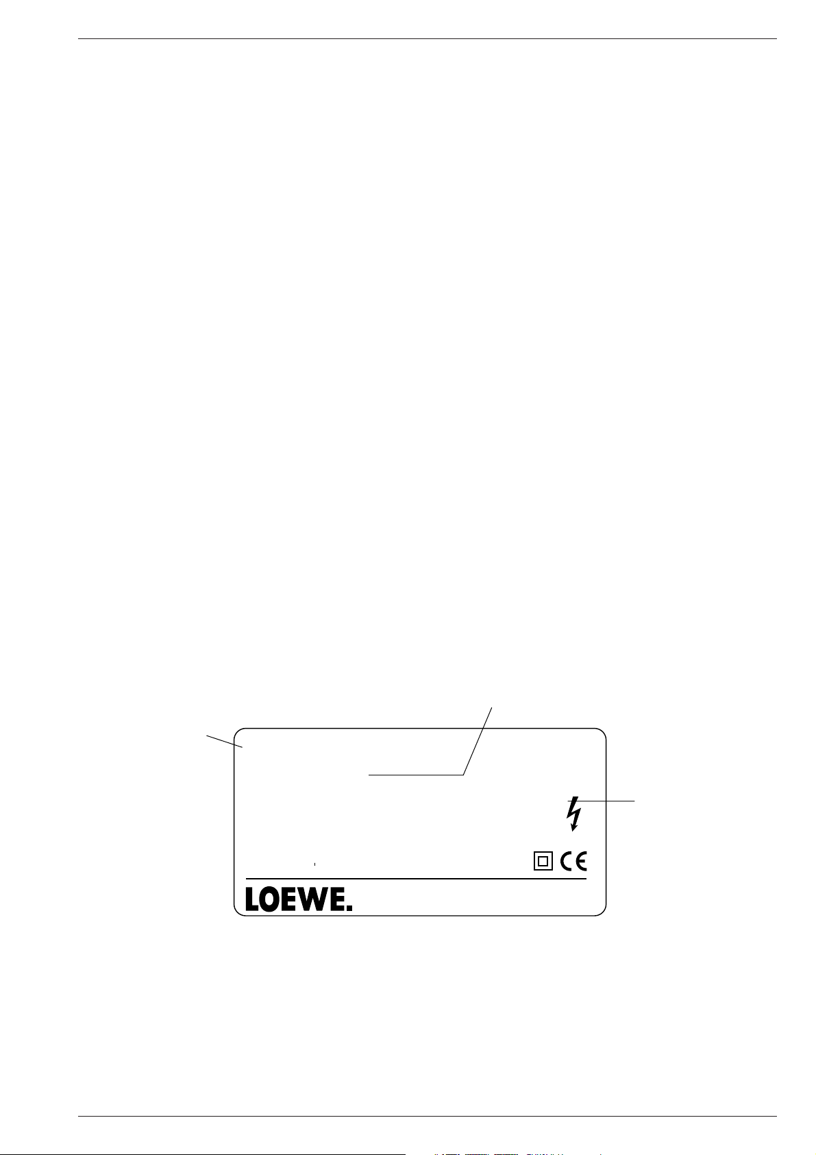
Messung des Kriechstromes im eingeschalte-
ten Zustand
1. Den Netzstecker direkt in eine Netzsteckdose stecken. Für diese
Messung keinen Trenntransformator verwenden.
2. Einen 2kΩ/10W-Widerstand in Serie mit einem von außen zugäng-
lichen Metallteil am Fernsehgerät und einer guten Erdung, z.B.
Wasserleitung, anschließen (Abb.1a).
3. Ein Wechselstrom-Voltmeter mit einem Eingangswiderstand von
1000 Ω/Volt oder größer verwenden, um die Spannung über dem
Widerstand zu messen.
4. Jedes zugängliche Metallteil prüfen, und an jedem Punkt die Span-
nung messen.
5. Den Netzstecker umgekehrt in die Steckdose stecken und jede der
obigen Messungen wiederholen.
6. Die Spannung darf an keinem der Punkte 1,4Veff. überschreiten.
Wird dieser Wert nicht eingehalten, besteht die Gefahr eines elek-
trischen Schlages, und das Fernsehgerät sollte daher repariert und
nachgeprüft werden, bevor es an den Kunden zurückgegeben wird.
Abb.1a Messung des Kriechstromes
Achtung, Röntgenstrahlung!
1. Potentielle Quellen von Röntgenstrahlung in Fernsehgeräten sind
das Hochspannungsteil und die Bildröhre.
2. Bei Verwendung eines Bildröhren-Prüfgerätes für den Service ist
sicherzustellen, dass es für die Belastung von 31,0kV geeignet ist,
ohne dass eine Röntgenstrahlung verursacht wird.
Messung der Hochspannung
1. Helligkeit auf Minimum stellen.
2. Die Hochspannung messen. Die Anzeige des Instrumentes sollte
29,0kV ± 0,7kV betragen. Falls die Anzeige diese Toleranzgrenzen
überschreitet, ist die sofortige Behebung nötig, um die Möglichkeit
vorzeitigen Komponentenausfalls zu verhüten.
3. Um die Möglichkeit von Röntgenstrahlung zu begrenzen, ist es
wichtig, dass nur die vorgeschriebene Bildröhre verwendet wird.
Anmerkung: Es ist wichtig, dass ein präzises, regelmäßig geprüf-
tes Voltmeter verwendet wird.
2KΩ / 10W
An zugängliche
Metallteile des
TV-Gerätes
Wasserleitung
(Erdung)
Wechselstrom-Voltmeter
Schaltungsaufbau für Prüfung im eingeschalteten Zustand
M 2103 Allgemeiner Teil / General Section
LOEWE.-Service 1 - 5
Note on electrostatic shielding
1. Electrostatically shielded MOS workstations
Components sensitive to electrostatic discharge must be handled at
workstation with electrostatic shielding. An electrostatically shielded
MOS workstation is fitted with discharge resistor which earth all
conductive materials, including the technician working there.
Dielectrics are discharged by air ionisation. The use of soldering
irons and measuring equipment at shielded workstation is only
possible in conjunction with isolating transformer in each of the
devices used. Measuring equipment chassis are also earthed with
discharge resistors.
2. Shielded packaging using conductive materials
To protect against electrostatic charges, electrically conductive
plastics are used for packaging and transport purposes. Conductive
plastics are available in the form of transparent protective bags,
foam plastic, film sheeting or containers. Sensitive components
requiring the use of protective packaging must only be packed and
unpacked at shielded workstations.
Safety Precautions
General Guide Lines
1. These television sets are isolated from the electric power mains by
the power transformer. An additional isolation transformer is
necessary for servicing work on the primary side of the power
transformer.
2. When servicing, observe the original lead dress in the high voltage
circuits. If a short circuit is found, replace all parts which have been
overheated or damaged by the short circuit.
3. Since many parts in the unit have special safely related
characteristics, always use genuine producer replacement parts.
Especially critical parts in the power circuit block should not be
replaced with other makers. Critical parts marked with S in the
circuit diagram and printed wiring board.
4. After servicing, see that all the protective devices such as insulation
barriers, insulation papers, shields and isolation R-C combinations
are correctly installed.
5. When the receiver is not being used for a long period of time, unplug
the power cord from the AC outlet.
6. Potentials as high as 29.9kV are present when this receiver is in
operation. Operation of the receiver without the rear cover involves
the danger of a shock hazard from the receiver power supply.
Servicing should not be attempted by anyone who is not familiar with
the precautions necessary when working on high voltage
equipment. Always discharge the anode of the picture tube to the
chassis before handling the tube.
7. After servicing make the following leakage current checks to prevent
the customer from being exposed to shock hazards.
Leakage current cold check
1. Unplug the AC cord and connect a jumper between the two prongs
of the plug.
2. Turn on the receiver’s power switch.
3. Measure the resistance value with an ohmmeter, between the
jumpered AC plug and each exposed metallic cabinet part on the
receiver, such as screw heads, aerials, connectors, control shafts
etc. When the exposed metallic part has a return path to the chassis
the reading should be between 4MΩ and 20MΩ. When the exposed
metal does not have are turn path to the chassis the reading must
be infinite.
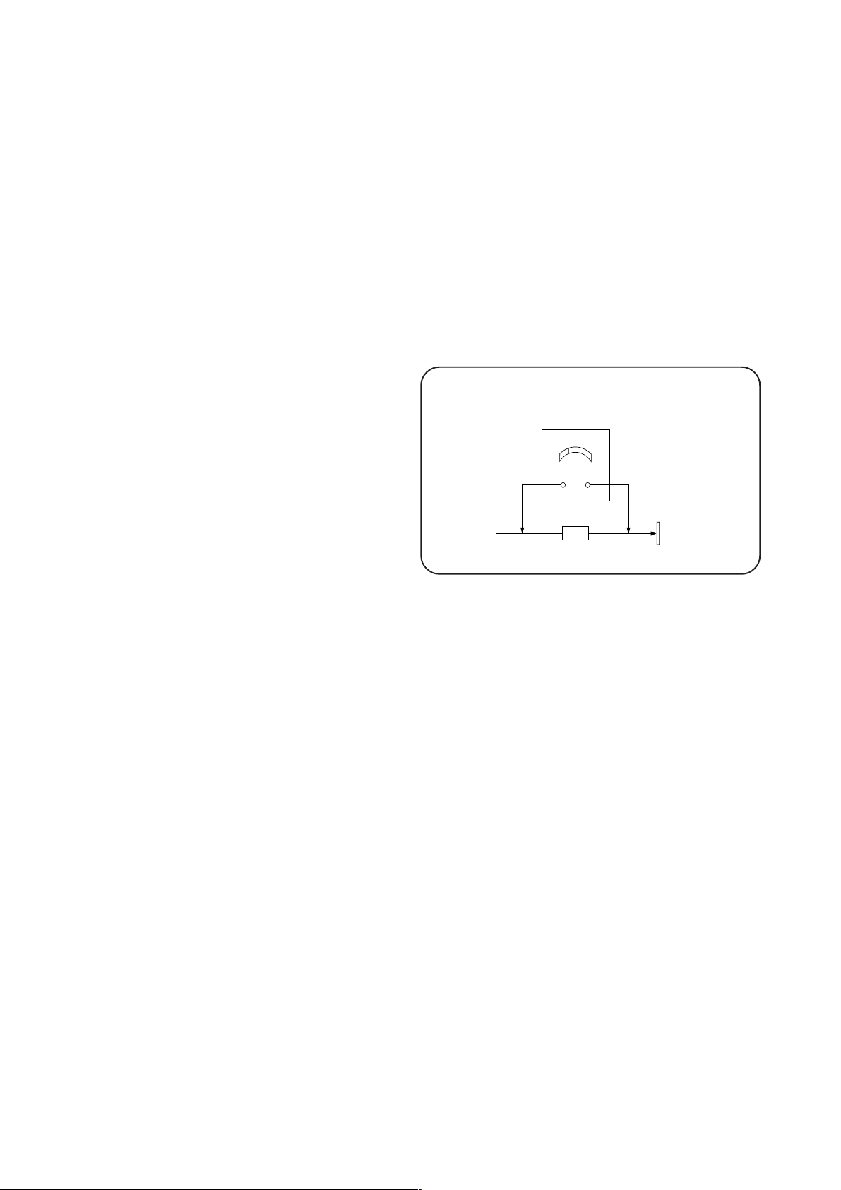
Leakage current hot check
1. Plug the AC cord directly into the AC outlet. Do not use an isolation
transformer for this check.
2. Connect a 2kΩ/10W resistor in series with an exposed metallic part
on the receiver and an earth such as a water pipe (fig.1a).
3. Use an AC voltmeter with high impedance to measure the potential
across the resistor.
4. Check each exposed Metallic part and check the voltage at each
point.
5. Reverse the AC plug at the outlet and repeat each of the above
measurements.
6. The potential at any point should not exceed 1.4Vrms. In case a
measurement is outside the limits specified, there is a possibility of
a shock hazard, and the receiver should be repaired and rechecked
before it is returned to the customer.
Fig.1a Leakage current hot check
X-Radiation warning
1. The potential sources of X-Radiation in TV sets are the high voltage
section and the picture tube.
2. When using a picture tube test jig for service ensure that the jig is
capable of handling 31.0kV without causing X-Radiation.
Measuring high voltage
1. Set the brightness to minimum.
2. Measure the high voltage. The meter should indicate 29.0kV ± 0.7kV
if the meter indication is out of tolerance, immediate service and
correction is required to prevent the possibility of premature
component failure.
3. To prevent any X-Radiation possibility, it is essential to use the
specified tube.
NOTE: It is important to use an accurate periodically calibrated high
voltage meter
2KΩ / 10W
To instrument`s
exposed
metallic parts
Water Pipe
(Earth)
A.C. Voltmeter
Hot check circuit
Allgemeiner Teil / General Section M 2103
1 - 6 LOEWE.-Service
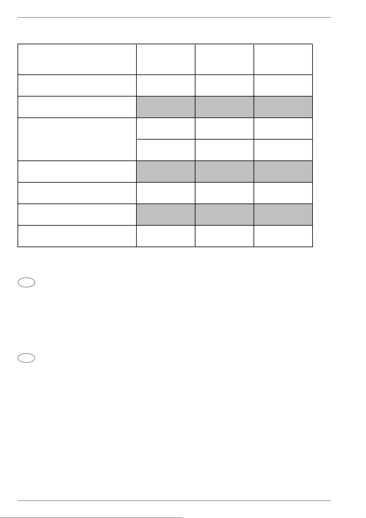
Modulübersicht / Module List
D
Bestellung von Ersatzteilen:
Benutzen Sie für die Bestellung von Ersatzteilen nicht die in den
Schaltplänen oder Platinenabbildungen verwendeten Sachnummern,
sondern die Ersatzteil-Materialnummern aus der Ersatzteilliste.
GB
Ordering of Spare Parts:
For ordering spare parts do not use the part numbers indicated on the
circuit diagrams or figures of the circuit boards but the spare part
numbers specified in the spare parts list.
Sachnummer
Part Number
Xelos M137 VT
M 2103
(VNM)
Xelos M155 VT
M 2103
(VNM)
Chassis
297040122200 297040122300
Tuner PLL 295043010100
••
Bildrohrplatte
CRT Panel
293051223700
•
–
293051223800
–
•
Prozessorplatte
Processor Board
293052191900
••
Fernbedienung
Remote Control CONTROL 100
87000.050
••
Mono SAT 3
61490.000
nachrüstbar
retrofittable
nachrüstbar
retrofittable
Lautspr. / Kopfhörerplatte
Loudsp. / Headphone Board
58482.000
nachrüstbar
retrofittable
nachrüstbar
retrofittable
M 2103 Allgemeiner Teil / General Section
LOEWE.-Service 1 - 7
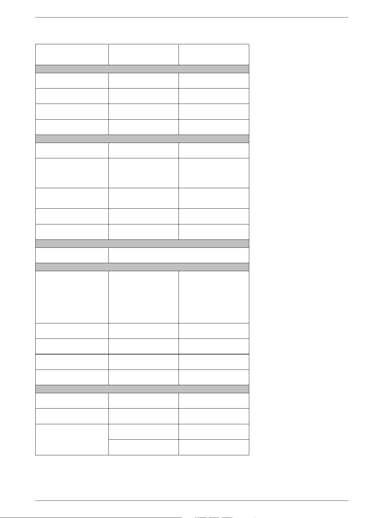
Technische Daten / Technical Data
XELOS M155 VT
VNM
(M 2103)
XELOS M137 VT
(M 2103)
Bildröhre / Picture Tube
Sichtbares Bild
Visible picture
51cm 34cm
Bildröhre
Picture tube
55cm (21")
Black Matrix
Philips 27,5kV small neck
37cm (14")
Black Matrix
Ablenkwinkel
Deflection angle
90° 90°
Bildwechselfrequenz
Vertical frequency
50Hz 50Hz
Elektronik / Electronic
Programmspeicherplätze
Programme positions
99 TV + 1 AV
(bei SAT-Nachrüstung / SAT retrofitting
299 TV/SAT/Radio)
99 TV + 1 AV
(bei SAT-Nachrüstung / SAT retrofitting
299 TV/SAT/Radio)
Tuner
PLL-Frequenzsynthesizer
Abstimmung UHF/VHF
PLL frequency synthesizer
tuning UHF/VHF
PLL-Frequenzsynthesizer
Abstimmung UHF/VHF
PLL frequency synthesizer
tuning UHF/VHF
TV-Normen
TV-Standards
PAL,
via AV: NTSC 4,43MHz
B/G
PAL,
via AV: NTSC 4,43MHz
B/G
Videotext
Teletext
7 Seiten TOP/FLOF-text
7-pages TOP/FLOF text
7 Seiten TOP/FLOF-text
7-pages TOP/FLOF text
Musikleistung
Music power
Mono 8W Mono 8W
Anschlüsse Front / Connections Front
Kopfhörer
Headphones
Anschlüsse Rückwand / Connections Rear Panel
Euro AV 1 (schwarz, black)
FBAS-Ein/Ausgang,
S-Video-Eingang, RGB-Eingang,
Digital Link
CCVS in-/output,
S-Video input, RGB input,
Digital Link
FBAS-Ein/Ausgang,
S-Video-Eingang, RGB-Eingang,
Digital Link
CCVS in-/output,
S-Video input, RGB input,
Digital Link
Lautsprecherbuchse
Loudspeaker socket
optional optional
Antennenanschluss terrestrisch
Antenna for terrestial reception
Koaxialbuchse
Coaxial socket
Koaxialbuchse
Coaxial socket
Antennenanschluss SAT
Antenna for SAT reception
nachrüstbar
retrofittable
nachrüstbar
retrofittable
Netzanschluss
Power supply plug
Netzkabel steckbar
Power cord plug-in type
Netzkabel steckbar
Power cord plug-in type
Netzteil / Mains Stage
Netzspannung (Regelbereich)
Mains voltage (variable)
230V±15% 230V±15%
Netzfrequenz
Mains frequency
50 / 60Hz 50 / 60Hz
Leistungsaufnahme
Power consumption
ca. 60W ca. 35W
Standby ca. 4W ca. 3W
Mono 3,5mm Buchse, schaltet internen Lautsprecher ab
Mono 3.5mm jack, switches off internal LS
Allgemeiner Teil / General Section M 2103
1 - 8 LOEWE.-Service
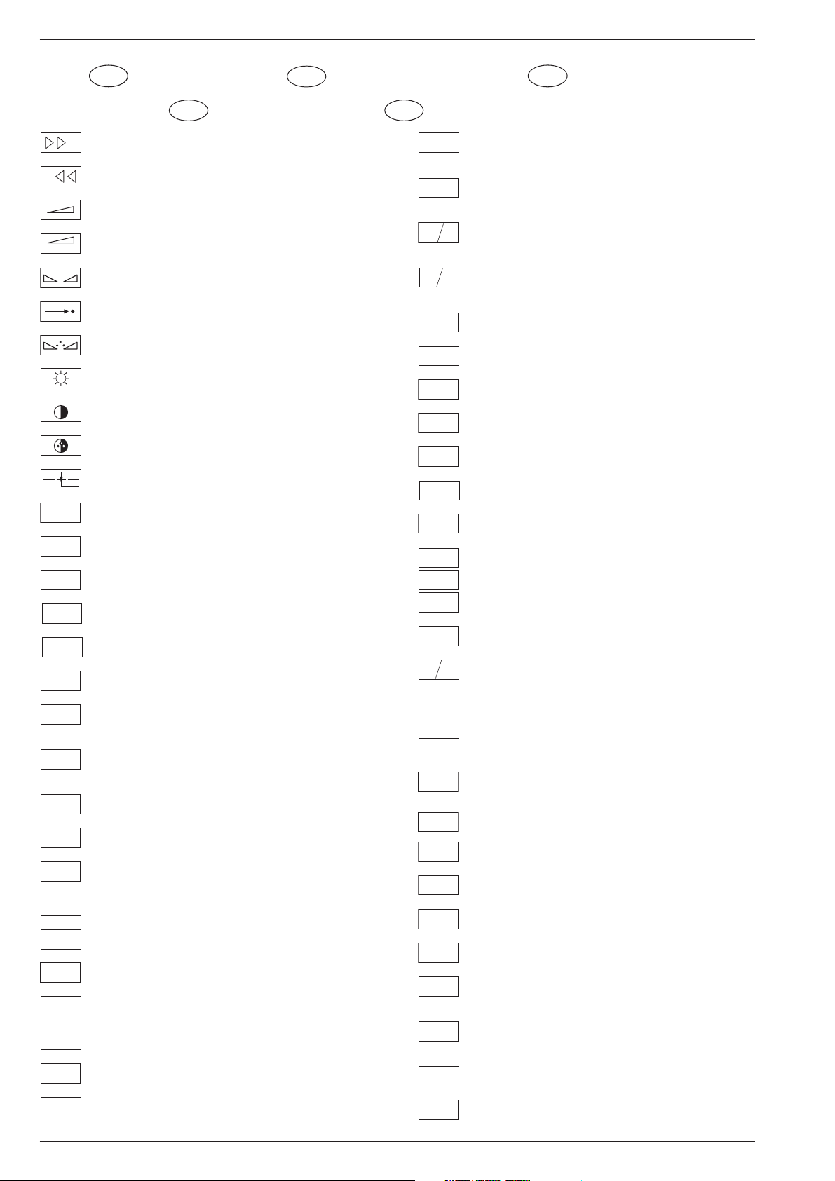
+
Feinabst. + / Fine tuning + / Réglage fine + / Sint. fine + / Sint. fina +
-
Feinabst. - / Fine tuning - / Réglage fine - / Sint. fine - / Sint. fina -
Lautstärke / Volume / Volume / Volume sonore / Volumen
REF
Referenz Lautstärke / Volume ref. volt. / Tens. de réf. vol. sonore /
Tens di rif. volume / Tens. ref. volumen
Balance / Balance / Balance / Balanciam. / Balance
Suchlauf / Self seek / Recherche autom. / Sint. autom. / Sintonia
automatica
Farbton / Tint / Teinte / Tinta / Tinte
Helligkeit / Brightness / Luminosité / Luminosita / Brillo
Kontrast / Contrast / Contraste / Contrasto / Contraste
Farbkontrast / Colour contrast / Contraste des coleurs / Contrasto
colore / Contraste de color
Schutzschaltung / Protection circuit / Circuit de sécurité / Circuito di
protezione / Circuito de protección
A-AM
Audio AM
ABK
(Burst Key): Burstaustastimpuls / Burst blanking pulse / Impulsion de
suppress. de burst / Imp. di soppress. del burst / Imp. supresion burst
AUDIO
Ton-Signal / Audio signal / Signal audio / Segnale audio / Señal audio
AUDIO-L
Ton-Signal links / Audio signal left / Signal audio gauche / Segnale
audio sinistra / Señal audio izquierda
AUDIO-R
Ton-Signal rechts / Audio signal right / Signal audio droit / Segnale
audio destra / Señal audio derecha
AUDIO
MAC
Tonsignal D2 Mac / Audio signal D2MAC / Signal audio D2MAC /
Segnale audio D2MAC / Señal de sonido D2MAC /
AUDIO
L-MAC
Tonsignal links D2 Mac / Audio signal left D2MAC / Signal audio
gauche D2MAC / Segnale audio sinistro D2MAC / Señal de sonido
izquirdo D2MAC
AUDIO
R-MAC
Tonsignal rechts D2 MAC / Audio signal right D2MAC / Signal audio
droit D2MAC / Segnale audio destro D2MAC / Señal de sonido
derecho D2MAC /
AUDIO
SUB
Audio Tieftöner / Audio sub woofer / Audio haut-parleur pour les
frequences basses / Audio toni bassi / Audio sonido bajo
AUDIO
TV
Audio-Signal FS Gerät / Audio signal TV set / Signal audio
téléviseur / Segnale audio TV / Señal audio TV
AUDIO
VCR
Tonsignal VCR Gerät / Audio signal VCR unit / Signal audio
magnetoscope / Segnale audio VCR / Señal audio VCR
A-ZF 1
Audio ZF 1 / Audio IF 1 / Audio FI 1 / Audio FI 1 / Audio FI 1
A-ZF 2
Audio ZF 2 / Audio IF 2 / Audio FI 2 / Audio FI 2 / Audio FI 2
B
Blau-Signal / Blue signal / Signal bleu / Segnale blu / Señal azul
BB
Basisband / Baseband / Bande de base / Banda base / Banda base
B EXT
Blau-Signal extern / Signal blue external /Signal bleu externe /
Segnale blu esterno / Señal azul externa
B
OSD
OSD-Einblendung blau / OSD blue / Eblouissement OSD bleu /
Visualizzazione OSD blu / Visualisacione OSD azul
B PIP
Blau-Signal PIP / PIP Blue signal / Signal bleu PIP / Segnale blu
PIP / Señal azul PIP
B/50
Blau - Signal - 50Hz vert.,15625Hz hor. / Blue signal - 50Hz vert.,
15625Hz hor. / Signal bleu - 50Hz vert., 15625Hz hor. / Segnale bleu
- 50Hz vert., 15625Hz hor. / Señal azul - 50Hz vert., 15625Hz hor.
B/100
Blau-Signal -100Hz vert., 31250Hz hor. / Blue signal -100Hz vert.,
31250Hz hor. / Signal bleu -100Hz vert., 31250Hz hor. / Segnale blu
-100Hz vert., 31250Hz hor. / Señal azul -100Hz vert., 31250Hz hor.
B-Y 50
B-Y -Signal - 50Hz vert., 15625Hz hor. / B-Y -Signal - 50Hz vert.,
15625Hz hor. / Signal B-Y - 50Hz vert., 15625Hz hor. / Segnale B-
Y - 50Hz vert., 15625Hz hor. / Señal B-Y - 50Hz vert., 15625Hz hor.
B-Y 100
B-Y -Signal - 100Hz vert., 31250Hz hor. / B-Y -Signal - 100Hz vert.,
31250Hz hor. / Signal B-Y - 100Hz vert., 31250Hz hor. / Segnale B-
Y - 100Hz vert., 31250Hz hor. / Señal B-Y - 100Hz vert., 31250Hz hor.
C
Kanalwahl / Channel selection / Sélection de canaux / Selez.
canale / Seleccion canal
CENTER
Mittelpunkt-Lautsprecher / Center loudspeaker / Haut-parleur de
centre / Alto parlante punto centrale / Altavoz del centro
CHIP
ADR
Chip Adresse / Chip adress / Chip direction / Indiri. del chip /
Direccion chip
CINCH
AUDIO L
Ton-Signal Cinch links / Audio signal cinch left / Signal audio cinch
gauche / Segnale audio cinch sinistra / Señal audio cinch izquierda
CINCH
AUDIO R
Ton-Signal Cinch rechts / Audio signal cinch right / Signal audio
cinch droit / Segnale audio cinch destra / Señal audio cinch derecha
CHROMA
Chroma Signal / Chroma signal / Signal dégree / Croma segnale /
Señal croma
CHROMA
S-VHS
Chroma S-VHS-Signal / Chroma S-VHS-Signal / Signal dégree de
S-VHS / Croma segnale S-VHS / Señal croma S-VHS
CLK
Clock
CL 1
CL 2
CSY
Composite Sync. Imp. für VT / Composite sync pulse for TT / Imp. de
sync. vidéo-composite pour TXT / Imp. hor. para Video Comp.
CS 100
Kombiniertes Hor./vert. Sync. Signal 31250Hz/100Hz (Composite
Sync.) / Combined hor./vert. sync signal 31250Hz/100Hz (Compo-
site Sync) / Signal synchr. hor./vert. combiné 31250Hz/100Hz
(Synchr. composité) / Segnale sincr. orizz./vert. 31250Hz/100Hz
(Sincr. Composito) / Señal combinada sincr. hor./vert. 31250/100Hz
(Sincr. compuesto)
DATA
Daten / Data / Données / Dati / Datos
DL
Verzögerungsleitung / Delay line / Ligne à retard / Linea di ritardo /
Linea de retardo
ENA
Freigabe / Enable / Autorisation / Consenso / Habilitacion
ENA
ZF
Freigabe ZF / IF Enable / Validation FI / Consenso FI / AutorizacónFI
ENABLE
FT
Freigabe FT / Finetuning enable / Autorisation Réglage fin / Abilitaz.
Sintonia fine / Habilitacion Sintoinia fina
ENABLE
LED
Freigabe LED / LED enable / Autorisation LED / Abilitaz. LED /
Habilitacion LED
ENABLE
TON
Freigabe Ton / Sound enable / Autorisation son / Abilitaz. audio /
Habilitacion sonido
EURO-AV
AUDIO-L
Audio-Signal EURO-AV links / Audio signal EURO-AV left / Signal
audio EURO-AV gauche / Segnale audio EURO-AV sinistra / Señal
audio izquierda EURO-AV
EURO-AV
AUDIO-R
Audio-Signal EURO-AV rechts / Signal audio EURO-AV right /
Signal audio EURO-AV droit / Segnale audio EURO-AV destra /
Señal audio derecha EURO-AV
EURO-AV
VIDEO
Video-Signal EURO-AV / Video signal EURO-AV / Signal video
EURO-AV / Segnale video EURO-AV / Señal video EURO-AV
F
Farb-Signal / Chroma signal / Signal chroma / Segnale chroma /
Señal croma
D
Schaltplansymbole
GB
Circuit Diagram Symbols
F
Symboles schéma
I
Simboli sullo schema
E
Simbolos en los esquemas

M 2103 Allgemeiner Teil / General Section
LOEWE.-Service 1 - 9
FBAS
FBAS-Signal / CCVS signal / Signal vidéo composite / Segnale video
composito / señal video compuesta
FBAS
CINCH
FBAS-Signal-Cinch Buchse / CCVS signal-cinch socket / FBAS-
prise à cinch / FBAS-presa cinch / FBAS-cinch
FBAS
MAC
FBAS-D2 MAC / D2MAC CCVS signal / Signal vidéo composite-
D2MAC / FBAS-D2MAC / FBAS-D2MAC
FBAS
TON
Basisband / Baseband / Bande de base / Banda base / Banda base
FBAS
TXT
FBAS-Videotext / CCVS videotext / Signal vidéo composite-
Télétexte / FBAS-Televideo / FBAS-Teletexto
FBAS
TEXT
FBAS
SYNC.
FBAS Sync. Signal / CCVS sync signal / Signal sync. vidéo col.
comp. / Segnal sincr. video col. comp. / Señal sincr. video
compuesta
FBAS
S-VHS
FBAS Signal S-VHS / CCVS signal S-VHS / Signal vidéo col. comp. S-
VHS / Segnal video col. comp. S-VHS / Señal video compuesta S-VHS
F
H
Hochspg. / EHT voltage / Haute tens. / Alta tens. / MAT
FRM
Rahmensignal / Frame signal / Signal d'encadrement / Segnale
cornice / Señal de marco
FT
Feinabstimmung / Fine tuning / Reglage fin / Sint. fine / Sint. fina
F
U
FU-Signal / FU-signal / Signal FU / Segnale FU / Senal FU
F
V
FV-Signal / FV-signal / Signal FV / Segnale FV / Senal FV
G
Grün-Signal / Green signal / Signal green external / Signal vert /
Segnale verde / Señal verde
G
OSD
OSD-Einblendung grün / OSD green / Eblouissement OSD vert /
Visualizzazione OSD verde / Visualisacione OSD verde
G PIP
Grün-Signal PIP / Green signal PIP / Signal green PIP/ Signal vert
PIP / Segnale verde PIP / Señal verde PIP
G EXT
Grün-Signal extern / Green signal vertical / Signal vert externe /
Segnale verde esterno / Señal verde externa
G/50
Grün-Signal - 50Hz vert.,15625Hz hor. / Green signal - 50Hz vert.,
15625Hz hor. / Signal vert - 50Hz vert., 15625Hz hor. / Segnale
verde - 50Hz vert., 15625Hz hor. / Señal verde -50Hz vert., 15625Hz hor.
G/100
Grün-Signal -100Hz vert., 31250Hz hor. / Green signal -100Hz vert.,
31250Hz hor. / Signal vert -100Hz vert., 31250Hz hor. / Segnale
verde -100Hz vert., 31250Hz hor. / Señal verde -100Hz vert.,
31250Hz hor.
GND - H
Nullpunkt Heizung / Ground filament / Point neutre-Chauffage /
Punto zero-Filamento / Punto medio filamento
HA
Horiz. Sync. Impuls / Horiz. Sync pulse / Impulsion synchro. horiz. /
Impulso sincro orizzontale / Impulso de sinc. horiz.
HDR
Horiz. Ansteuerimpuls / Horiz. drive pulse / Impulsion de commande
horiz. / Impulso comando orizzontale / Impulso de control horiz.
HC
Horiz. Klemmimpuls / Horiz. clamp pulse / Impulsion de serrage
horiz. / Impulso comando orizzontale / Impulso de garras horiz.
H
SYNC
Horizontaler Sync-Impuls / Horizontal Sync impuls / Sync impuls
horizontale / Sinc impulso orrizontale / Impulso sync horizontal
HFB
Horiz. Rückschlagimpuls / Horiz. flyback / Impulsion de retour
horiz. / Impulso rotorno orizzontale / Impulso de retroceso horiz.
HS
Hor. Sync. Implus für VT / Hor. sync pulse for TT / Imp. de sync. hor. pour
TXT / Imp. sincr. orizz. per Televideo / Imp. hor. para Video Comp.
I2S CL
Digitale Datensignale / Digtital data signals / Signal donneé digital /
Segnali dati digitali / Señal datos digital
I2S TER
I2S IN
I2S WS
I BEAM
Strahlstrom / Current beam / Current rayon / Corrante del irradire /
Corriente de haz
ICL
I
2
C Bus -Clock
IR
Infrarot-Signal / Signal infrared / Signal infra-rouge / Segnale
infrarosso / Señal infrarojo.
IM
CLOCK
I
2
C Bus -Clock
IM
IDENT
I
2
C Bus -Kennung / I
2
C-Bus Identification / Identification I
2
C-Bus /
Ident. I
2
C-Bus, Identification I
2
C-Bus
IM
RESET
I
2
C Bus -Reset
IR CLK
Infrarot Clock / Infrared clock / Signal I.R. horloge / Clock segnale
R.I. / Clock infrarojos
IR DATA
Infrarot Signal / Infrared signal / Signal I.R. / Segnale infrarosso /
Data infrarrojos
IR
VIDEO
Infrarot Signal Video / Infrared signal video / Signal I.R. video /
Segnale infrarosso video / Data infrarrojos video
KB
Keyboard
KH
AUDIO-L
Tonsignal Kopfhörer links / Audio signal headphone left / Signal
audio gauche de casque / Segnale audio sinistra cuffia / Señal audio
izquierda auriculares
KH
AUDIO-R
Tonsignal Kopfhörer rechts / Audio signal headphone right / Signal
audio droit de casque / Segnale audio sinistra cuffia / Señal audio
derecha auriculares
L
Lautstärke / Volume / Volume / Volume sonore / Volumen
LED
Leuchtdiode / Light emitting diode / Diode lumineuse / Diodo
luminoso / Diodo luminescente
M
Speicher Taste / Memory button / Touche mémoire / Tasto di
memoria / Puls. memoria
MEGA
LOGIC
Megalogic Daten / Megalogic data / Megalogic dates / Dati
Megalogic / Megalogic datas
MODE
Modus / Mode / Mode / Modo / Modo
NIC CLK
NICAM Clock / Clock NICAM / Horloge NICAM / Clock NICAM /
Clock NICAM
NORM
Norm Taste / TV standard select button / touche de norme / Tasto
norma / Puls. de norma
OWA
Ost-West Ansteuerimpuls / East-west drive impuls / Impulsion de
commande Est-Ouest / Impulso comando Est-Ovest / Impulso de
control Este-Oeste
P
Programm / Program / Programme / Programma /Programa
P/C
Programm-Kanalwahl / Program channel selection / Progr. sélection
de canaux / Progr. selez.canale / Progr. selec. canal
PIP
Bild im Bild / Picture in picture / Image dans l'image / PIP / Imagen
en la imagen
P1
Progr. Taste / Progr. button / Touche Progr. / Tasto Progr. / Puls.
Progr.
R
Rot-Signal / Red signal / Signal rouge / Segnale rosso / Señal rojo
REMOTE
Fernbedienung / Remote control / Telecommande / Telecomando /
Mando a distancia
R
OSD
OSD-Einblendung rot / OSD red / Eblouissement OSD rouge /
Visualizzazione OSD rosso / Visualisacione OSD rojo
R PIP
Rot-Signal PIP / Red signal PIP / Signal rouge PIP / Segnale rosso
PIP / Señal rojo PIP
R EXT
Rot-Signal extern / Signal red external / Signal rouge externe /
Segnale rosso esterno / Señal rojo externa
R-Y 50
R-Y -Signal - 50Hz vert., 15625Hz hor. / R-Y -Signal - 50Hz vert.,
15625Hz hor. / Signal R-Y - 50Hz vert., 15625Hz hor. / Segnale R-
Y - 50Hz vert., 15625Hz hor. / Señal R-Y - 50Hz vert., 15625Hz hor.
R-Y 100
R-Y -Signal - 100Hz vert., 31250Hz hor. / R-Y -Signal - 100Hz vert.,
31250Hz hor. / Signal R-Y - 100Hz vert., 31250Hz hor. / Segnale
R-Y - 100Hz vert., 31250Hz hor. / Señal R-Y - 100Hz vert., 31250Hz hor.
S
Sonderkanal / Special channel / Canal special / Canale speciale /
Canal especial

Allgemeiner Teil / General Section M 2103
1 - 10 LOEWE.-Service
SB
Strahlstrombegrenzung / Beam current lim. / Lim. cour. de faisceau /
Lim. corr. di raggio / Corriente media de haz
SCL
I
2
C-Bus Clock
SCL 100
Schneller I
2
C-Bus Clock / I
2
C-Bus clock high speed / I
2
C-Bus grande
vitesse / I
2
C-Bus veloce / Clock del I
2
C-Bus de alta velocida
SDA
I
2
C-Bus Daten / I
2
C-Bus data / I
2
C-Bus données / I
2
C-Bus dati /
I
2
C-Bus datos
SHIFT
VIDEO
Dynamische vert. Versch. 25Hz, aktiv bei Video u. Mix Betrieb /
Dynam. vert. shift 25Hz, active on video and mix operation / Decal
dynam. de l'image 25Hz, actif sur video et fonction. mixte / Spostam.
vert. dinam. 25Hz, attivo con video e. funzionam. misto / Desplaz.
dinamico vert. 25Hz, activo con video Y funciones mixtas
SHIFT
TEXT
Dynamische vert. Versch. 25Hz, aktiv bei Standbild u. VT / Dyn. vert.
shift 25Hz, active on freeze-frame and Teletext / Decal dynam. de
l'image 25Hz, actif sur arret immage et Vidéotext (Antiope) / Spostam.
vert. dinam. 25Hz, attivo con fermo immag. e Televideo / Desplaz.
dinamico vert. 25Hz, activo con imagen parada Y Videotexto
SS
Schutzschaltung / Protection circuit / Cablage protecteur / Pot. de
prot. / Circuito de proteccion
SSB
Spitzenstrahlstrombegrenzung / Peak beam current limiting / Lim.
de faisceau crete / Lim. corr. catod. di pico / Corrente pico de haz
SSC
Supersandcastle
SSC
PIP
Supersandcastle PIP
SSC 100
Supersandcastle 100Hz vert., 31250Hz hor.
SSC 50
Supersandcastle 50Hz vert., 15625Hz hor.
SUR-
ROUND
Surround
SYNC
Sync.-Signal / Sync.-Signal / Signal sync / Segnale sync. / Señal de sync.
SYNC.
BTX
Sync. BTX / Viewdata Sync / Sync. Télétext / Sincr. Videotel / Sincr.
Videotexto
SYNC.
VT
Sync. VT / Sync. Teletext / Sync Vidéotexte / Sincr. Televideo / Sincr.
Videotexto
SW
Schwarzwert / Black level / Niveau du noir / Livello del nero / Nivel de negro
TE
TEXT-Freigabe / TEXT enable / Autorisation TEXTE / Abilitaz.
TELEVIDEO / Habilatation TEXTE
T1
Bei Zweiton, Ton 1 / On two channel sound, sound 1 / Pour double
son, son 1 / In bicanale, audio 1 / En dual, sonido 1
T2
Bei Zweiton, Ton 2 / On two channel sound, sound 2 / Pour double
son, son 2 / In bicanale, audio 2 / En dual, sonido 2
TT
Tieftöner / Woofer / Haut-parleur pour les frequences basses / Toni
bassi / Sonido bajo
U
FOC
Fokusspg. / Focussing volt. / Tens. de focalis. / Tens di focalizz. /
Tens focalizacion
U
G1
Spg. Gitter G 1 / Volt. grid G1 / Tens grille G 1 / Tens. griglia G1 / Tens.
rejillas G 1
U
H
Hochspannung / High voltage / Haute tension / EAT / Alte tension
U
G2
Schirmgitter Spg. / Screen-grid volt. / Tens. de grille - écran / Tens.di
griglia schermo / Tens. de rejilla
VA
Vertikaler Ansteuerimpuls / Vert. drive pulse / Impulsion de commande
verticale / Impulso di comando verticale / Impulso de control vertical
VB
VCL
VCR - Clock
VDR
Freigabe Anzeigebaustein / Display enable / Autorisation pour module
indicateur / Modulo indicazione / Habilitacion modulo indicacion
VG
Vert. Gegenkopplung / Vert. feedback / Contre-reaction verticale /
Controreazione vert. / Aliment. neg. vert.
VIDEO
Video Signal / Video signal / Signal vidéo / Segnale video / Señal video
VT DATA
Videotext Daten / Teletext data / Données Teletexte / Linea dati
Televideo / Data Teletexto
VT SCL
Videotext Clock / Teletext clock / Signal horloge Vidéotext / Clock
Televideo / Clock Teletexto
VT SDA
I
2
C Bus: VT Daten / Teletext data / Données Vidéotext / Dati
Televideo / Data Teletexto
V SYNC
Vertikaler Sync-Impuls / Vertical Sync impuls / Sync impuls vertical
/ Sinc impulso vertical / Impulso sync vertical
Y
Y-Signal / Y Signal / Signal Y /Segnale Y / Señal Y
Y 50
Y -Signal - 50Hz vert., 15625Hz hor. / Y -Signal - 50Hz vert., 15625Hz
hor. / Signal Y - 50Hz vert., 15625Hz hor. / Segnale
Y - 50Hz vert., 15625Hz hor. / Señal Y - 50Hz vert., 15625Hz hor.
Y 100
Y - Signal - 100Hz vert., 31250Hz hor. / Y -Signal - 100Hz vert.,
31250Hz hor. / Signal Y - 100Hz vert., 31250Hz hor. / Segnale
Y - 100Hz vert., 31250Hz hor. / Señal Y - 100Hz vert., 31250Hz hor
ZF
Zwischenfrequenz / IF / FI / FI / FI
U
AFC
Schaltspg. AFC / AFC switching volt. / Tens. de commut. AFC/ Tens.
di commut. AFC / Tens. conmut. CAF
U
AV
Schaltspg. AV / Switching volt. AV / Tens. de commut. AV / Tens. di
commut. AV / Tens. conmut. AV
U
B1
Schaltspg. Band 1 / Switching volt. band 1 / Tens. de commut.
bande 1 / Tens. di commut. banda 1 / Tens. conmut. de banda 1
U
B2
Schaltspg. Band 3/ / Switching volt. band 3 / Tens. de commut.
bande 3 / Tens. di commut. banda 3 / Tens. conmut. de banda 3
U
BA
Schaltspg. Bildamplitude / Switching voltage vertical amplitude /
Tension de coupure amplitude dìmage / Tensione di commutaz.
ampiezza d'imagine / Tension de conm. amplitude de imagen di
commut. PAL / Tens. conmut. PAL
U
BTX
Schaltspg. BTX / Switching volt. BTX (Viewdata) / Tens. commut.
Télétext / Tens. commut. VIDEOTEL / Tens. conmut. Teletexto
U
C-AV
Schaltspg. Camera Wiederg. über Camera-AV Eingang / Switching
volt. cam. playback via Camera-AV input / Tens de commut pour lec.
de camera par l'entree Camera-AV / Tens.de commut. in riproduz.
camera tramite ingresso Camera-AV / Tens. de serv. reprod. camera
a traves de la entrada Camera-AV
U
DATA
Schaltspg. Datenbetr. / Switching volt. data mode / Tens. de com-
mut. fonct. données / Tens. di commut. dati / Tens conmut. datos
U
DATA
EXT
Schaltspg. U Data extern / Switching volt Data ext. / Tension de
commutation U Data externe / Tens. di commutazione U-Data
esterno / Tensión de conmutatón externa U
U
DATA
OSD
Schaltspg. für Bildschirm-Einblendung / Switching volt. for On
Screen Display / Tens. commut. pour eblouissement On Screen
Display / Tens. commut. per di visualizzazione On Screen Display /
Tens. conmut. para On Screen Display
U
DEEM
Schaltspg. Deemphasis / Switching volt. deemphasis / Tens. com-
mut. desaccent. / Tens. commut. deenfasi / Tens. conmut. deenfasis
U
DS
Schaltspg. Dolby-Surround / Switching volt. Dolby-Surround / Tens.
commut. Dolby-Surround / Tens. commut. di Dolby-Surround / Tens.
de conmut. Dolby-Surround
U
EURO-
AV
Schaltspg. EURO-AV / Switching volt. EURO-AV / Tens. de commut.
EURO-AV / Tens. di commut. EURO-AV / Tens. conmut. EURO-AV
U
EU-AV
CINCH
Schaltspg. EURO-AV-Cinch-Buchse / Switching volt. EURO-AV-
Cinch socket / Tens. commut. prisa Scart - Cinch / Tens. commut.
presa Scart -Cinch / Tens. conm. EURO-AV - Cinch
U
FBAS
Schaltspannung für Video-Ausgang EURO-AV Buchse / Switch.
voltage for video output EURO-AV socket / Tension de commut.
pour sortie vidéo EURO-AV / Tension commut. per presa d'uscita
video EURO-AV / Tension de conmut. para salida EURO-AV
U
HIFI
Schaltspg. HIFI / Switching voltage HIFI / Tens. de commut. HIFI /
Tens di commut. HIFI / Tens. conmut. HIFI
U
HIFI
MUTE
Stummschaltung HiFi / Muting volt. HiFi / Commutation de silence
HiFi / Silenzametno HiFi / Muting HiFi
U
HUB
Schaltspg. HUB / Switching volt. deviation / Tens. commut.
déviation / Tens. commut. deviazione / Tens. conmut. deviacion
M 2103 Allgemeiner Teil / General Section
LOEWE.-Service 1 - 11
U
IDENT
Schaltspg. Signalkennung AV 3 / Switching volt. signal identification
AV 3 / Tens de commut.identification de signal AV3 / Tens. commut.
identificazione segnale / Tens. conmut. identifi. segñal AV3
U
KH
MUTE
Stummschaltung Kopfhörer / Muting volt. headphone / Commutation
de silence casque / Silenzamento cuffia / Muting auriculares
U
KLEMM
Gleichspannung für SAT-Basissignal / DC for SAT basic signal /
Tens. continue pour SAT base signal / Tens continua per segnale
SAT base / Tens. continua para segñal SAT base
U
KOIN
50/60Hz
Schaltspg. Koinz. / Switching volt. coinc. / Tens de commut. coinc. /
Tens di commut. coinc. / Tens. conmut. coinc.
U
KOIN
VQ
Schaltspg. Koinz. mit Videoquelle verknüpft / Coinc. switching volt.
linked with video source / Signal de coincid. combiné avec source
video / Tens. di commut. a coinc. combinata con sorg video segñal
de coincidencia combinada con video
U
LED
Schaltspg. LED / Switching volt. LED / Tens de commut. LED / Tens.
commut. LED / Conmut. LED
U
Leucht-
punkt
Schaltspg. Leuchtpunktunterdrückung / Switching volt. beam spot
suppression / Tens. de commut. suppress. du spot lumineux / Tens.
soppr. punto luminoso / Tens. de conmut. filtro supresor del punto luz
U
LNC
OFF
Schaltspg. LNC "Aus" / Switching volt. LNC "OFF" / Tens. de
commut. LNC "OFF" / Tensione di commut. "Spento" LNC / Tension
LNC "OFF"
U
MAC
Schaltspg. D2MAC / Switching volt. D2MAC / Tension de
commutation D2MAC / Tens. di commutazione D2MAC / Tensión de
conmutación D2MAC
U
MUTE
Stummschaltung / Muting / Silencieux / Silenziamento /Muting
U
NF 1
Schaltspg. NF 1 / Switching volt. AF 1 / Tension commut. BF 1 / Tens.
commut BF 1 / Tens. conm. BF 1
U
NF 2
Schaltspg. NF 2 / Switching volt. AF 2 / Tension commut. BF 2 / Tens.
commut BF 2 / Tens. conm. BF 2
U
NIC
Schaltspg. NICAM / Switching volt. NICAM / Tens. de commut.
NICAM / Tens. commut. NICAM / Tens. de conmut. NICAM
U
NORM
Schaltspg. Norm / Switching volt. Norm / Tens. de commut.
standard / Tens. di commut. Norma / Tens. conmut. Norma
U
PAL
Schaltspg. PAL / Switching volt. PAL / Tens. de commut. PAL / Tens.
di commut. PAL / Tens conmut. PAL
U
POL.
Schaltspg. Polarität / Switching volt. polarity / Tension commut.
polarite / Tens. commut. polarita / Tens. conmut polarizacion
U
POWER
OFF
Schaltspg. Ökoschalter / Switching volt. eco switch / Tens. de
commut. interr. eco. / Tens. commut. interr. ecologico / Tens.
conmut. interr. ecol.
U
PV
Schaltspg. Panorama View / Switching volt. Panorama View / Tens.
de commut. Panorama View / Tens. commut. Panorama View /
Tens. conmut. Panorama View
U
RESET
Schaltspg. Reset / Switching volt. Reset / Tens. commut. Reset /
Tens. commut. Reset / Tens. conmut. Reset
U
RGB
Schaltspg. RGB1 - RGB2 / Switching volt. RGB1 - RGB2 / Tens. de
commut. RGB1 - RGB2 / Tens. di commut. RGB1 - RGB2 / Tens.
conmut. RGB1 - RGB2
U
SCHUTZ
Schaltspg.-Schutzfunktion / Switching volt.-protective func. / Tens
de commut.-sécurité / Tens. di commut.-funz di protez. / Tens.
conmut.-proteccion
U
SEC
Schaltspg. SECAM / Switching volt. SECAM / Tens. de commut.
SECAM / Tens. di commut. SECAM / Tens. conm. SECAM
U
STBY
Schaltspg. Standby / Switching volt. Standby / Tens. commut.
Veille / Tens. commut. Standby / Tens. conmut. Standby
U
S-VHS
Schaltspg. S-VHS / Switching volt. S-VHS / Tens.de commut.
S-VHS / Tens. de commut. S-VHS / Tens. de conmut. S-VHS
U
TON
1/2
Schaltspg. Ton 1-2 / Switching volt. sound 1-2 / Tens. commut. audio
1-2 / Tens. commut. son 1-2 / Tens. conmut. son 1-2
U
UHF
Schaltspg. UHF / UHF switching volt. / Tens. de commut. UHF / Tens
di commut. UHF / Tens. conmut. UHF
U
VHF
Schaltspg. VHF / VHF switching volt. / Tens. de commut. VHF / Tens
di commut. VHF / Tens. conmut. VHF
U
VQ
Schaltspg. Videoquelle / Switching volt. video source / Tens. de
commut. source video / Tens. di commut. sorg. video / Tens conmut.
video
U
WISCH
Schaltspg. Wischerkontakt / Schwitching voltage temp. contact /
Tens. de commut. contact fugitif / Tens. commut. contatto tempora-
neo / Contacto supresor tens. de conmut.
U
W/N
Schaltspg. ZF breit - schmal / IF switching volt. wide - narrow / Tens.
commut. FI large - etroit / Tens. commut. FI larga - stretta / Tens. FI
ancho - estrecho
U
I / III
Schaltspg. Bandwahl / Band sel. switching volt. / Tens. de commut.
select. bande / Tens. di commut. selez. banda / Tens. conmut. selec.
banda
U
14V
14V Schaltspg. / 14V switching volt. / Tens. commut. 14V / Tens.
commut. 14V / Tens. de conm. 14V
U
22kHz
22kHz Schaltspg. / 22kHz switching volt. / Tens. commut. 22kHz /
Tens. commut. 22kHz / Tens. de conm. 22kHz
0/3/6/9V
0/3/6/9V Schaltspg. / 0/3/6/9V switching volt. / Tens. commut.
0/3/6/9V / Tens. commut. 0/3/6/9V / Tens. de conm. 0/3/6/9V
U
4.5MHz
Schaltspg. 4,5MHz / Switching volt. 4.5MHz / Tens. de commut.
4,5MHz / Tens. di commut. 4,5MHz / Tens conmut. 4,5MHz
U
50/60
Hz
Schaltspg. 50-60Hz / Switching volt. 50-60Hz / tens. de commut.
50-60Hz / Tens. di commut. 50-60Hz / Tens. conmut. 50-60Hz
U
AFC
Regelspg. AFC / AFC contr. volt. / Tens. de regul. AFC / Tens. di
contr. AFC / Tens. regul. CAF
U
SAT
AFC
Regelspg. AFC Satellitentuner / AFC contr. volt. SAT tuner / Tens.
de regul. AFC tuner SAT / Tens. di contr. AFC Tuner SAT / Tens.
regul. CAF Tuner SAT
U
AGC
Feldstärkeabhängige Spg. / Fieldstrength-depent volt. / Contr. auto-
matique de gain / Tens. dipent. intens. campo / Contr. autom. de gain
tens. CAG
U
RE
Regelspg. / Contr. volt. / Tens. de regul. / Tens. di contr. / Tens regul.
U
TUN.
Abstimmspg. Tuner / Tuning volt. tuner / Tens. d'accord tuner / Tens.
di sintonia tuner / Tens. sintonia tuner
U
τ
Regelspg. Verzög. / Delayed contr. volt. / Tens. de regul. retardee /
Tens. regul. retardada
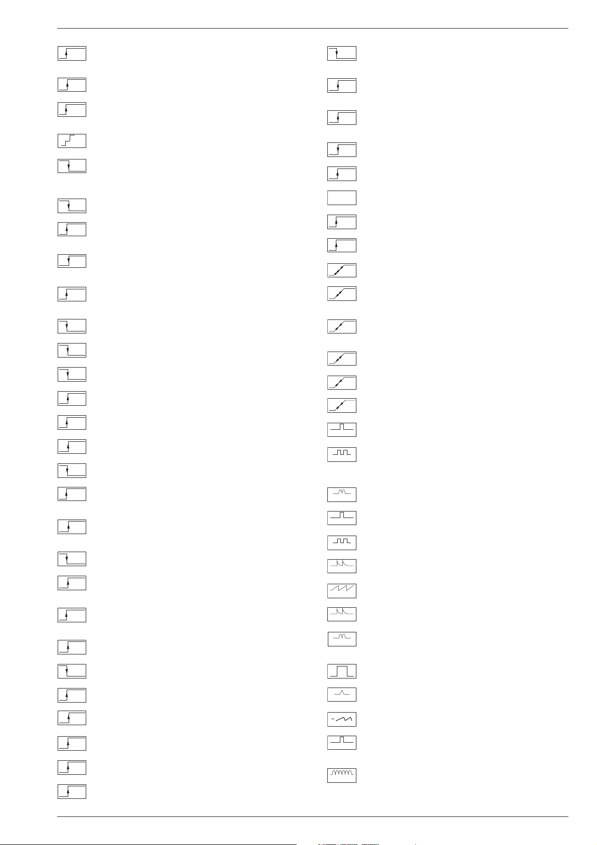
HOR.
Horizontale Ansteuerung / Horiz. drive / Synchr. lignes / Pilotaggio
orizz. / Exitación horiz.
HOR.2FH
31250Hz Ansteuerimp. für Zeilenendstufe / 31250Hz Triggering
pulse for horiz. output / 31250Hz commande pour l'étage final
lignes / Imp. Pilotaggio di 31250Hz per stadio finale di riga / Impulso
de exitación 31250Hz para paso final de lineas
VERT.
Vert. Parabel / Vert. parabolic signal / Signal parabolique vert. /
Segnale parab. vert. / Senal parabolica vert.
VERT.
Vert. Tastimpuls / Vert. Gating pulse / Imp. trame / Imp. a cadenza
vert. / Imp. cuadro
VER.2FV
Vert. Tastimpuls 100Hz / Vert. Gating pulse 100Hz / Imp. trame
100Hz / Imp. a cadenza vert. 100Hz / Imp. cuadro 100Hz
VERT.
Vert. Sägezahn / Vert. saw tooth / Signal dent de scie / Dente di sega
vert. / Dientede sierra vert.
VERT.
Vert. Tastimpuls / Vert. Gating pulse / Imp. trame / Imp. a cadenza
vert. / Imp. cuadro
VERT. 100
Vert Sägezahn 100Hz / Vert saw tooth 100Hz / Signal dent de scie
100Hz / Dente di sega vert. 100Hz / Dientede sierra vert. 100Hz
VERT. 100
Vert. Parabel 100Hz / Vert. parabolic 100Hz signal / Signal parabo-
lique 100Hz vert. / Segnale parab. vert. 100Hz / Senal parabolica
vert. 100Hz
Tastimpuls / Gating pulse / Impuls de declenchement / Impulso a
cadenza / Imp. puerta
REF.
Ref. Impuls hor. / Reference impulse hor. / Imp. de refer.hor. / Imp.
di rifer. hor. / Imp. refer. horiz.
Klemmung Ein-Aus / Clamping On-Off / Clampage Marche-Arrêt /
Clamping Ins.-Disins. / Clamping Enc.-Apag.
PULSE
Pulse für Polarotor / Pulses for Polar-Rotor / Impulsions Rotor de
Polariastion / Impulsi per Rotore Polarizzazione / Impulsos dara
Polarrotor
O/W
O-W Amplitude / E-W amplitude / Amplitude E-O / Ampiezza E-O /
Amplitud E-O
Allgemeiner Teil / General Section M 2103
1 - 12 LOEWE.-Service
. . . V Gleichspannungswert / DC voltage / Valore tensione continua / Tension
continue / Valor de tensión continua
. . . V
ss
. . . ms/cm
. . . Hz
Spitze-Spitze - Wert / Peak to peak value / Valore picco-picco / Crête-
crête / Valor pico a pico
Zeitbasis des Oszilloskops / Time base of the oscilloscope / Base del
tempo dell´oscilloscopio / Base de temps de l´oscilloscope/ Base de
tiempo del oscilocopio
Frequenz / Frequency / Frequenza / Fréquence / Frecuencia
Die Spannungswerte an den Oszillogram-
men entsprechen Näherungswerten!
The voltages indicated in the oscillograms
are approximates!
I valori delle tensioni indicati sugli oscillo-
grammi sono approssimativi !
Les valeurs de tension indiquées pour les
oscillogrammes sont des valeurs approxi-
matives!
Los valores de tensión en los oscilogramas
son aproximados!
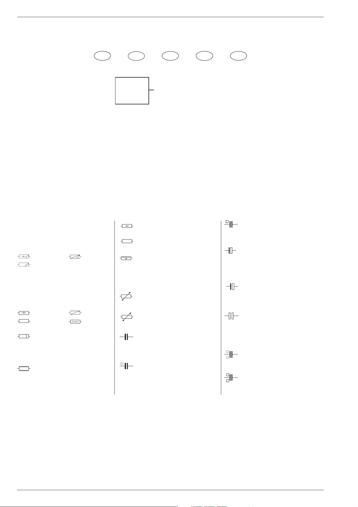
Metallschichtwiderstände
Metal film resistors
Resistenza a strato metallico
Resistencia de capa metálica
Film métallique
Kohleschichtwiderstände
Carbon film resistors
Resistenza a strato di carbone
Resistencia de capa de carbón
Film carbonique
Metalloxidwiderstand
Metal oxid resistor
Resistenza ad ossido metallico
Resistencia de óxido metálico
Métaloxide
Schwer entflammbarer Widerstand
Flame resistant resistor
Resistenza anti-infiammabile
Resistencia ininflamable
Ininflammable
PTC
NTC
SI-R
SI-R
DIN 0207
DIN 0204
DIN 0414
DIN 0204
DIN 0207
DIN 0414
DIN 0617
Sicherungswiderstand
Safety resistor
Resistenza di sicurezza
Resistencia con resorte de seguridad
Rés. fusible
Drahtwiderstand m. Wattangabe
Wire wound resistor w. wattage
Resistenza a filo
Resistencia bobinada (Disipación)
Bobinée avec ind. puissance
Heißleiter / NTC resistor
Termistore NTC / Resistencia CNT
Varistor (CTN)
Kaltleiter / PTC resistor
Termistore PTC / Resistencia CPT
Varistor (CTP)
Keramikkondensator
Ceramic capacitor
Condensatore ceramico
Condensador cerámico
Céramique
Kondensator, Capacitor
Condensatore, Condensador
Condensador, 250 V=
Kondensator, Capacitor
Condensatore, Condensador
Condensador, 630 V=
Elektrolytkondensator
Electrolytic capacitor
Condensatore elettrolitico
Condensador electrolitico
Electrolytique
Tantal-Elektrolytkondensator
Tantalum electrolytic capacitor
Condensatore elettro. al tantalio
Condensador de tantalio
Tantale
bipolarer Elektrolytkondensator
bipolar electrolytic capacitor
Condensatore elettrolitico bipolare
Condensador electrolitico bipolar
Electrolytique bipolaisé
Kondensator, Capacitor
Condensatore, Condensador
Condensador, 400 V=
Kondensator, Capacitor
Condensatore, Condensador
Condensador, 1000 V=
Hinweise zu den Bauteilen / Hints to Components / Istruzioni sui Componenti /
Observaciones sobre los Componentes / Precautions a observer
K
+
T
+
Hinweise zu den Oszillogrammen / Hints to the Oscillograms / Note relative agli Oscillogr./
Indications pour les Oscillogrammes / Observaciones con respecto a los Oscilogramas
D
GB
I
F
E

M 2103 Allgemeiner Teil / General Section
LOEWE.-Service 1 - 13
Service- und Sonderfunktionen
Taste "M" –> Aufruf des TV-Menüs oder zurück ins vorherige Menü
Taste "E" –> Menüausstieg
Cursertaste 3 4 Anwählen der Dialogzeile
Cursertaste 1 2 Einstellungen ändern
1. Einschaltfunktionen
1.1 Mittelwerte / Notdatensatz laden (ROM-Daten)
Fernbedientaste "P-" gedrückt halten und das Gerät mit dem Netz-
schalter einschalten. Dadurch wird z. B. nach Austausch des IC82501
(NVM) das Gerät mit dem Notdatensatz gestartet.
Mit diesem Vorgang werden die Grund-Daten aus dem ROM des
Prozessors IC81500 in den NVM IC82501 kopiert:
IC82501: (gerätespezifische Daten, über das TV-Menü einstellbar)
- Farb- und Ton-Normen
- Decodereinstellungen
- Umkehrpunkt
- OSD Position
- ATS-Reset
- Hotel-Mode on/off
- AGC und AFC
- Analogwerte (Lautstärke, Helligkeit usw.)
- Bildschärfe
- Security on/off
- Geometrieabgleich
- Programmdaten (Kanal- und Feinabstimmung, Senderkennung)
Danach über das TV-Menü die persönlichen Werte, Bildgeometrie
eingeben.
1.2 Kindersicherung Generalaufhebung
Die Zahl "3001" hebt die Sperre dauerhaft auf.
Diese Zahlenkombination ist für die Geheimzahl gesperrt.
1.3 Software -Versionsnummer
"TV-Menü" aufrufen.
Taste "V=" zeigt die Software-Versionsnummer an.
1.4 Einschalten mit dem zuletzt gesehenen Programm
Der beim Ausschalten eingestellte Programmplatz wird beim Ein-
schalten wieder aufgerufen (Last station memory).
2. Sonderfunktionen
"TV-Menü" –> "Einstellungen" –> "Sonderfunktionen".
2.1 Öko-Netzschalter aktivieren bzw. deaktivieren (optional)
Die Dialogzeile "Eco switch" aufrufen.
Einstellungen "1h…3h" oder "aus".
Das Gerät schaltet sich nach der eingestellten Zeit aus.
In Stellung "aus" wird diese Funktion nicht genutzt.
Durch längeren Tastendruck der Taste Ǽ in Stellung TV-Ein wird der
Netzschalter ausgelöst und schaltet das Gerät komplett ab, diese
Funktion wird generell ausgeführt.
2.2 Einblendzeit
Die Dialogzeile "Einblendzeit" aufrufen.
Die Dauer der OSD-Einblendungen ist von 2…9s einstellbar.
2.3 Video AV
Die Dialogzeile "Video AV" aufrufen.
Umschaltbar zwischen "VHS" und "SVHS".
2.4 Farbnorm AV
Die Dialogzeile "Farbnorm AV" aufrufen.
Umschaltbar zwischen "auto", "PAL" und "NTSC".
2.5 Service
Die Dialogzeile "Service" aufrufen.
Mit Taste "OK" Einstieg in das offene Menü.
3. Bild-Einstellungen
"TV-Menü" –> "Bild".
Folgende Werte sind einstellbar:
Kontrast 0…63
Helligkeit 0…63
Farbe 0…63
Schärfe 0…5
oder
Mit der "roten" Taste "Kontrast" aufrufen.
Mit der "grünen" Taste "Helligkeit" aufrufen.
Mit der "blauen" Taste "Farbe" aufrufen.
Die Analogwerte werden beim Verlassen des Menüs automatisch
gespeichert.
4. Ton-Einstellungen
"TV-Menü" –> "Ton".
4.1 Ton
Sie können die maximale Lautstärke einstellen.
Dieser Wert gilt auch für Kopfhörer.
4.2 AVC (Automatic Volume Control)
In Stellung "ein" wird bei großen Senderhüben die Lautstärke automa-
tisch an den normalen Hub angepasst.
5. Programme im TV-Menü
"TV-Menü" –> "Programme".
5.1 Automatisch suchen.
Wählbar ab welchen Programmplatz, für welchen Standort (Land) die
automatische Speicherung beginnen soll.
5.2 Manuell einstellen
Manuelle Eingabe von Programm, Bereich, Kanal, Fein, Name und
AV-Eingang.
5.2.1 Maximale Programmnummer (Umkehrpunkt)
"Manuell einstellen" aufrufen.
Programmnummer aufrufen, ab der die Programmplätze gesperrt
werden sollen. In der Dialogzeile Kanal "C 00" einstellen. Mit "roter"
Taste speichern. Danach können im Programm-Mode mit den Tasten
"P+/P-" die nachfolgenden Programme nur bis zu dem mit "C 00"
belegten Programmplatz fortgeschaltet werden.
5.2.2 AV-Eingang
"Manuell einstellen" aufrufen.
AV-Eingang auf aus/ein stellen.
5.3 Sortieren/löschen
Sortieren und löschen der einzelnen Programmplätze.
5.4 Name eingeben/ändern
Eingeben oder ändern des Sendernamens.
6. Offene Service-Einstellungen
"TV-Menü" –> "Einstellungen" –> "Sonderfunktionen" –> "Service".
6.1 TV-Programmer (nicht bei SAT-Nachrüstung)
Einstellbar "aus", "TV >> Ext", "Ext >> TV".
Ext >> TV Programmerdaten werden zum TV-Gerät übertragen
und das TV-Gerät programmiert.
TV >> Ext Programmplatzbezogene Daten vom TV-Gerät werden
zum Programmer übertragen und dort gespeichert.
Durch Drücken der Taste "OK" werden obengenannte Funktionen
gestartet.
Nach Beendigung der Übertragung wird im OSD "OK" angezeigt.
Bei fehlerhafter Übertragung erscheint die Meldung "Error".
6.2 VT-Sprachgruppe
Auswahl zwischen West/East und West/TR
6.3 Schwarz. Bildschirm
Auswahl zwischen "ein" und "aus".
6.4 Service Code (Händlermenü)
Durch die Eingabe der Zahlen 8640 gelangen sie ins Service-menü.

Allgemeiner Teil / General Section M 2103
1 - 14 LOEWE.-Service
7. Service-Einstellungen für den Fachhandel (Händlermenü)
"TV-Menü" –> "Einstellungen" –> "Sonderfunktionen" –> "Service" –>
"Service Code" –> Kennziffer "8640" .
7.1 Service-Menü
Nach Eingabe der Codezahl "8640" kann der Fachhändler den Geräte-
abgleich laut Menüführung durchführen für:
- GEOMETRIE
- WHITE ADJUSTMENT
- AGC
- AFC 38.9 MHz
- OSD horizontal
- OSD vertical
- RC5 Code
- Initial Mode
Abgleich: Seite 2-1
7.2 OSD-Lage
Horizontale oder vertikale Lage des Einblend-Menüs verschieben und
Dialogzeile "End" mit "with mem" beenden.
7.3 Hotel-Mode
7.3.1 Hotel-Mode aktivieren
Verdeckte Funktion, in keiner Dialogzeile sichtbar.
"Initial mode" anwählen und Kennziffer 8640 eingeben "Initial mode"
wird rot angezeigt.
Nach Speicherung der Dialogzeile End mit "with mem" ist der Hotel-
Mode aktiv.
Bei aktiviertem "Hotel-Mode" ist:
- die zuletzt eingestellte Lautstärke im Tonmenü die maximale Laut-
stärke die gespeichert wird.
7.3.2 Hotel-Mode deaktiveren
Fernbedientaste "Ǻ" gedrückt halten und das Gerät mit dem Netz-
schalter einschalten.
"Initial mode" anwählen und Kennziffer 8640 eingeben "Initial mode"
wird schwarz angezeigt.
7.4 Initial Mode
Das TV-Gerät wird in den Fabrik-Auslieferungszustand versetzt.
ATS-Reset und Analogdatensatz werden im NVM überschrieben.
Das ATS-Reset Bit wird gesetzt.
7.5 Schutzschaltungen deaktivieren
- Horizontal- und Vertikal-Schutzschaltung:
Basis und Emitter des CT50055 verbinden.
- Horizontal- Schutzschaltung:
Basis und Kollektor des CT57113 verbinden.
- Vertikal- Schutzschaltung: C50052 kurzschließen.
Achtung: Nach beendeter Reparatur Schutzschaltungen unbedingt
aktivieren.

M 2103 Allgemeiner Teil / General Section
LOEWE.-Service 1 - 15
Service and Special Functions
"M" button –> Call up "TV-menu" or go back to previous menu.
"E" button –> Exit menu.
Cursor buttons 3 4 –> Select dialogue line.
Cursor buttons 1 2 –> Change setting.
1. Switching-on Options
1.1 Loading the Average Values / Emergency Data Set (ROM Data)
Press and hold down the "P-" button on the remote control and switch
on with the mains button. After replacement of IC82501 (NVM), for
example, the TV set is started with the emergency data set.
In doing so, the basic data is read out from the ROM of processor
IC81500 and loaded into the NVM IC82501:
IC82501: (data specific to the TV can be set via the TV Menu):
- chroma and audio standards
- decoder settings
- reversing point
- OSD position
- ATS reset
- Hotel mode on/off
- AGC and AFC
- analog values (volume, brightness etc.)
- picture sharpness
- security on/off
- geometry adjustment
- programme data (channel and finetuning, station ident)
Subsequently enter your personal values, picture geometry via the TV
Menu.
1.2 Cancelling the Parental Lock Continuously
To cancel the parental lock, enter the number 3001.
This number is locked for the code number.
1.3 Software Version Number
Call up the "TV-menu".
Pressing the "V=" button displays the software version number.
1.4 Switching on with the Last Viewed Programme.
The channel position which has been selected when switching off is
recovered when switching on again (last station memory).
2. Special Functions
"TV-menu" -> "Settings" -> "Special functions".
2.1 Activating or Deactivating the Economy Mains Switch (option)
Select the "Eco switch" dialogue line.
Select the setting "1h…3h" or "off".
The TV receiver switches off at the predetermined time.
With the "off" setting, this function is not used.
By pressing the mains button Ǽ a longer time with the TV on, the mains
switch is released and switches the TV set completely off. This function
is carried out in a general way.
2.2 Display Time
Select the "Display time" dialogue line.
The duration of the OSD display can be set between 2…9s.
2.3 Video AV
Select the "Video AV" dialogue line.
The setting "VHS" or "SVHS" can be selected.
2.4 Colour AV
Select the "Colour AV" dialogue line.
The settings "auto", "PAL" and "NTSC" can be selected.
2.5 Service
Select the "Service" dialogue line.
Press the "OK" button to access the open menu.
3. Picture Settings
"TV Menu" –> "Picture".
The following settings are possible:
Contrast 0…63
Brightness 0…63
Color 0…63
Sharpness 0…5
or:
press the "red" button to select "Contrast",
press the "green" button to select "Brightness",
press the "blue" button to select "Colour".
When exiting the menu, the analog values are automatically saved.
4. Sound Settings
"TV Menu" –> "Sound".
4.1 Max. volume
You can set the maximum volume.
This setting applies also for the headphones.
4.2 AVC (Automatic Volume Control)
With the "on" setting selected, the volume is automatically adjusted to
the normal amplitude when high volume amplitudes are received.
5. Programs in the TV Menu
"TV Menu" –> "Programs".
5.1 Automatic Search
You can select from what programme position and for what place of
installation (country) the automatic saving is to be started.
5.2 Manual Adjustment
Manual entry of Program, Range, Channel, Fine, Name, and AV input.
5.2.1 Maximum Programme Number (Reversing Point)
Select "Manual adjustment".
Select the programme number which is to be the highest selectable
programme position. Select "C 00" in the Channel dialogue line. Press
the "red" button to save the setting. When this is done, only the
programme positions up to the position "C00" can be selected using
the "P+/P-" buttons in programme mode.
5.2.2 AV Input
Select "Manual adjustment".
Set the AV input to "on" or "off".
5.3 Sort/Delete
With this function you can sort or delete individual programme positions.
5.4 Enter/Change Name
With this function you can enter or change the station name.
6. Open Service Settings
"TV Menu" –> "Settings" –> "Special Functions" –> "Service".
6.1 TV-Programmer (not with SAT retrofit kit)
The settings "off", "TV >> Ext", "Ext >> TV" can be selected.
Ext >> TV The Programmer data is transferred to the TV set and
the TV set is programmed.
TV >> Ext Programme position specific data is transferred from
the TV set to the Programmer and stored there.
Pressing the "OK" button starts the above functions.
When the data transfer is completed, "OK" is displayed on the screen.
In the event of a faulty transfer, "Error" is displayed.
6.2 Teletext Language
You can select between West/East and West/TR
6.3 Black Screen
You can select between "on" and "off".
6.4 Service Code (for the dealer)
Enter the digits 8640 to access the Service Menu.
 Loading...