


G7 CABLE MOTION™ GYM SYSTEM
CLASS H
PART # 8352100 REV. A VERSION: LFG7-001 DATE: 08-10-07

TABLE OF CONTENTS
Safety Statement . . . . . . . . . . . . . . . |
.2 |
Assembly Instructions . . . . . . . . . . . . . |
.7 |
Gym Dimensions. . . . . . . . . . . . . . . . .3 |
General Maintenance . . . . . . . . . . . . . . |
19 |
|
Components List . . . . . . . . . . . . . . . . . |
4 |
Warranty Statement . . . . . . . . . . . . . . . |
20 |
Required Hardware . . . . . . . . . . . . . . . |
6 |
Contact Information. . . . . . . . . . . . . . . .21 |
|
IMPORTANT SAFETY INFORMATION
THERE IS A RISK ASSUMED BY INDIVIDUALS WHO USE THIS TYPE OF EQUIPMENT. TO MINIMIZE RISK FOLLOW THESE RULES!
1.Before using, read all the warnings and instructions on the use of this machine including the workout book and instructional DVD. Use only for intended exercise. DO NOT modify the machine.
2.Obtain a medical exam before beginning any exercise program.
3.Keep body and clothing free of all moving objects.
4.Inspect the machine before use. DO NOT use it if it appears damaged. DO NOT attempt to fix a broken or jammed machine. Notify your authorized Life Fitness dealer before use and have repairs made by an authorized service technician.
5.Be certain that weight pin is completely inserted. Use only the pin provided by the manufacturer. If unsure, call your authorized Life Fitness dealer.
6.Never pin the weights or prop plate into an elevated position. DO NOT use the machine if found in this condition. DO NOT attempt to fix. Notify your authorized Life Fitness dealer.
7.Inspect cables and their connections before using machine. Pay particular attention to the cable ends. DO NOT attempt to fix. Notify your authorized Life Fitness dealer before use and have repairs made by an authorized service technician.
8.Make sure all spring loaded pull pins are fully engaged in the adjustment position before use.
9.Children and pets must not be allowed near this machine. Supervise teenagers.
Please note:
*Thank you for purchasing the Life Fitness G7 Cable Motion Gym System. Please read these instructions thoroughly and keep them for future reference. This product must be assembled on a flat, level surface to assure its proper function.
*DO NOT securely tighten any frame connections until the entire frame has been assembled, unless otherwise stated.
NOTE: In a continual effort to improve our products, specifications are subject to change. © 2007 Life Fitness, a division of Brunswick Corporation. All rights reserved.
Life Fitness is a trademark of Brunswick Corporation.
www.LifeFitness.com
2
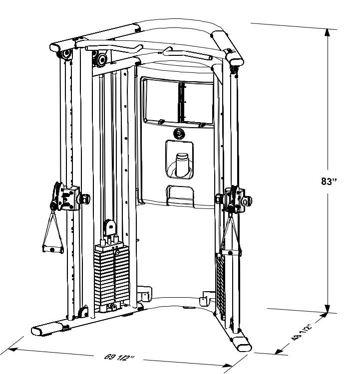
GYM DIMENSIONS
Weight: |
720 lbs |
Resistance Ratio: |
1:2 |
3
COMPONENTS LIST
ITEM NO. |
QTY. |
PART NO. |
DESCRIPTION |
|
|
|
|
1 |
1 |
8172901 |
LEFT TOWER |
2 |
1 |
8178003 |
TOP BRACKET TUBE |
3 |
1 |
8178002 |
MIDDLE BRACKET TUBE |
4 |
1 |
8178004 |
BOTTOM BRACKET TUBE |
5 |
1 |
8351601 |
LEFT SLIDE TUBE (WITH ROLLER CARRIAGE) ASSEMBLY |
6 |
1 |
8257401 |
RIGHT U BRACKET |
7 |
1 |
8256901 |
LEFT U BRACKET |
8 |
1 |
8316401 |
RIGHT SWIVEL PULLEY |
9 |
1 |
8151301 |
LEFT SWIVEL PULLEY |
10 |
1 |
8351701 |
RIGHT SLIDE TUBE (WITH ROLLER CARRIAGE) ASSEMBLY |
11 |
1 |
8172001 |
RIGHT TOWER |
12 |
1 |
8176701 |
CHIN UP BAR |
13 |
2 |
3258301 |
PULLEY, 88.9 OD X 10 X 25.4 |
14 |
4 |
8228901 |
COVER, PULLEY, PARTIAL |
15 |
4 |
7634401 |
GUIDEROD RETAINER |
16 |
4 |
8264701 |
GUIDE ROD ASSEMBLY |
17 |
30 |
7935301 |
WEIGHT PLATE, 10LB, CASTEEL |
18 |
2 |
8262501 |
TOP PLATE 15, CASTEEL, SPCL |
19 |
2 |
8315601 |
HEAD PLATE PULLEY ASSEMBLY |
20 |
4 |
8264301 |
CUSHION, WEIGHT STACK, 65MM |
21 |
2 |
8265601 |
CABLE, BE, BE |
22 |
2 |
8312601 |
FOOT, EXTENSION, FLOV |
23 |
2 |
8167301 |
SIDE SHROUD |
24 |
6 |
8244301 |
KIOSK BRACKET |
25 |
1 |
8275801 |
KIOSK ASSEMBLY |
43 |
2 |
7936701 |
WEIGHT PIN & RING |
44 |
4 |
8229001 |
COVER, PULLEY, FULL |
45 |
2 |
7944401 |
D RINGS |
46 |
1 |
8288601 |
THIGH STRAP |
47 |
1 |
7745801 |
FOOT STRAP |
48 |
1 |
8280401 |
TOWEL |
49 |
1 |
8348101 |
MARKER |
50 |
2 |
8112801 |
HANDLES |
51 |
2 |
2103801 |
SNAP LINKS |
52 |
1 |
8288701 |
DVD |
53 |
1 |
7777301 |
TOUCH UP PAINT, PLT |
54 |
1 |
8313701 |
HARDWARE BAG |
55 |
1 |
8280501 |
WATER BOTTLE |
|
|
|
|
4

COMPONENTS LIST
HARDWARE LISTED BELOW
ITEM NO. |
QTY. |
PART NO. |
DESCRIPTION |
|
|
|
|
26 |
32 |
3256201 |
M10 X20MM SCREW |
27 |
52 |
3264201 |
M10 WASHER |
28 |
20 |
3242201 |
M5 HEX SCREW |
29 |
20 |
3264101 |
M6 WASHER |
30 |
4 |
3256208 |
M10 X 55MM SCREW |
31 |
2 |
3256206 |
M10 X 45MM SCREW |
32 |
13 |
3242002 |
M10 HEX NYLOCK NUT |
33 |
7 |
3256211 |
M10 X 70MM SCREW |
34 |
2 |
3264601 |
M10 SOCKET HEAD NUT |
35 |
2 |
3256207 |
M10 X 50MM SCREW |
36 |
2 |
3264501 |
PULLEY RETAINER |
37 |
4 |
3232421 |
RETAINER RING |
38 |
4 |
3240502 |
M10 X 50mm HEX TENSION SCREW |
39 |
32 |
3262501 |
M5 SHOULDER SCREW |
40 |
12 |
3264901 |
M10 X 20MM SCREW |
41 |
12 |
3265001 |
M10.5 WASHER |
|
|
|
|
REQUIRED TOOLS LISTED BELOW
* 7mm ALLEN WRENCH (2)
* 4mm ALLEN WRENCH
* 5mm ALLEN WRENCH
* 17mm WRENCH
* EXTERNAL SNAP RING PLIERS
* ADJUSTABLE WRENCH
* PHILLIPS SCREW DRIVER
5

HARDWARE:
6
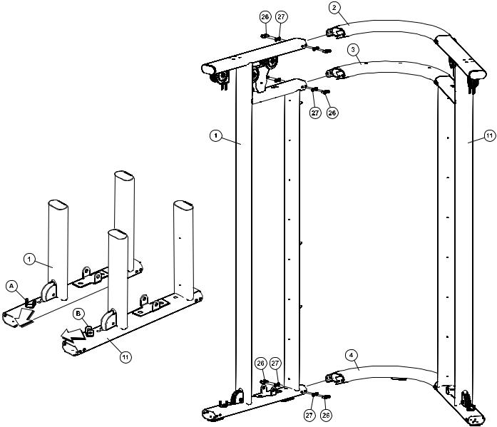
NOTE: Two person assembly is recommended.
STEP 1:
Make sure the LEFT TOWER (1) and the RIGHT TOWER (11) are positioned correctly prior to assembly. The LEFT U BRACKET (A) and RIGHT U BRACKET (B) should point towards each other as shown in the above illustration.
Use four M10 x 20mm SCREWS (26) and four M10 WASHERS (27) to connect the BOTTOM BRACKET TUBE (4) to the LEFT TOWER (1). Finger tighten only.
NOTE: THE BOTTOM BRACKET TUBE (4) HAS A RUBBER PAD ATTACHED TO IT TO MAKE CONTACT WITH THE FLOOR.
Repeat the above process using the TOP BRACKET TUBE (2) and the MIDDLE BRACKET TUBE (3).
NOTE: THE TOP BRACKET TUBE (2) DOES NOT HAVE ANY HOLES. THE MIDDLE BRACKET TUBE (3) HAS THREE HOLES THROUGH THE TOP AND BOTTOM.
Repeat all of the above steps to attach the TOP (2), MIDDLE (3), and BOTTOM (4) BRACKET TUBES to the RIGHT TOWER (11).
7
 Loading...