


FIT 1.0 CM
GYM SYSTEM
USER GUIDE
WARNING:
Read and follow all directions for each step to insure proper assembly of this product.
CLASS -S
PART # 7946001 REV.A
VERSION: FSFCM1-0102-001
DATE: 06-13-05
TABLE OF CONTENTS
Safety Statement............. |
2 |
Tool Requirements |
|
General Notes................. |
2 |
and Hardware................. |
6 |
Gym Dimensions............. |
3 |
Assembly Instructions..... |
7-18 |
Components List............. |
4 |
General Maintenance....... |
19-20 |
Exploded View............... |
5 |
Warranty Statement......... |
21 |
|
|
Contact Information........ |
22 |
IMPORTANT SAFETY INFORMATION
THERE IS A RISK ASSUMED BY INDIVIDUALS WHO USE THIS TYPE OF
EQUIPMENT. TO MINIMIZE RISK FOLLOW THESE RULES!
1. Before using, read all the warnings and instructions on the use of this machine including the wall chart and instructional DVD. Use only for intended exercise. DO NOT modify the machine.
2.Obtain a medical exam before beginning any exercise program.
3.Keep body and clothing free of all moving objects.
4.Inspect the machine before use. DO NOT use it if it appears damaged. DO NOT attempt to fix a broken or
jammed machine. Notify your authorized Life Fitness dealer before use and have repairs made by an authorized service technician.
5. Be certain that weight pin is completely inserted. Use only the pin provided by the manufacturer. If unsure, call your authorized Life Fitness dealer.
6. Never pin the weights or prop plate into an elevated position. DO NOT use the machine if found in this condition. DO NOT attempt to fix. Notify your authorized Life Fitness dealer.
7. Inspect cables and their connections before using machine. Pay particular attention to the cable ends. DO NOT attempt to fix. Notify your authorized
Life Fitness dealer before use and have repairs made by an authorized service technician.
8.Make sure all spring loaded pull pins are fully engaged in the adjustment position before use.
9.Children and pets must not be allowed near this machine. Supervise teenagers.
Please note:
*Thank you for purchasing the Life Fitness Fit 1.0 CM Gym System. Please read these instructions thoroughly and keep them for future reference. This product must be assembled on a flat, level surface to assure its proper function.
*DO NOT securely tighten any frame connections until the entire frame has been assembled, unless otherwise stated.
NOTE: In a continual effort to improve our products, specifications are subject to change © 2005 Life Fitness, a division of Brunswick Corporation. All rights reserved. Life Fitness is a trademark of Brunswick Corporation
www.LifeFitness.com
2
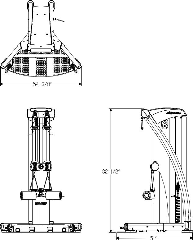
GYM DIMENSIONS
3
COMPONENTS LIST
|
ITEM NO. |
QTY. |
PART NO. |
DESCRIPTION |
|
1 |
1 |
LEA7728202 |
PTD ASSY, FRONT UPRIGHT |
|
2 |
1 |
LEA7701602 |
PTD ASSY, BASE PLATFORM |
|
3 |
1 |
LEA7729802 |
PTD ASSY, ROLLER PAD ADJ. |
|
4 |
1 |
LEA7701702 |
PTD ASSY, LEFT UPRIGHT |
|
5 |
1 |
LEA7701802 |
PTD ASSY, RIGHT UPRIGHT |
|
6 |
1 |
LEA7611702 |
WLDMT, GUIDE ROD |
|
7 |
1 |
LEA7746102 |
PTD ASSY, TOP PULLEYS |
|
8 |
1 |
LEA7945902 |
PTD ASSY, FRONT SHROUD |
|
9 |
1 |
LEA7761602 |
PTD ASSY, TOP SHROUD |
|
10 |
1 |
LEA7762402 |
PTD ASSY, HEAD PLATE PULLEY |
|
11 |
2 |
LEA7754502 |
PTD ASSY, FLOATING PULLEYS |
|
12 |
1 |
LEA7952301 |
PTD ASSY, HEAD PLATE 20" GRAY |
|
13 |
2 |
LEA7682002 |
PLATE, REAR BOTTOM |
|
14 |
1 |
LEA7622001 |
ASSY, SELECTOR PIN |
|
15 |
1 |
LEA7755301 |
COVER TOP |
|
16 |
1 |
LEA7755401 |
COVER TOP BACK |
|
17 |
1 |
LEA7755501 |
COVER TOP FRONT |
|
18 |
1 |
LEA7755601 |
COVER MID BACK |
|
19 |
1 |
LEA7755701 |
COVER MID FRONT |
|
20 |
1 |
LEAAK58-00245-0000 |
MEDALLION;"BUG"; PUR |
|
21 |
2 |
LEA3245501 |
COLLAR, 1" ID SHAFTALUM |
|
22 |
2 |
LEA6920201 |
GUIDE ROD, 1" O.D. 10GA X 73 |
|
23 |
2 |
LEA6020602 |
BEARING, FLG 1/2 ID X 5/8 OD X 1/2 |
|
24 |
2 |
LEA7749701 |
CUSHION, WEIGHT STACK |
|
25 |
14 |
LEA3223401 |
SCREW, 10-32 X 6 PHL PAN TT ST BZ |
|
26 |
10 |
LEA3226003 |
SCREW, 6-20 X 8 PHL PAN PLT BZ |
|
27 |
4 |
LEA3249205 |
.375 HXS SOC CS X 1.00 |
|
28 |
28 |
LEA3102514 |
WASHER, 3/8 SAE |
|
29 |
1 |
LEA3102701 |
NUT, HEX |
|
30 |
4 |
LEA3245401 |
BSHNG, GUIDE ROD 1 ID X 1-1/2 |
|
31 |
6 |
LEA3249203 |
.375 HXS SOC CS X .750 |
|
32 |
1 |
LEA7705402 |
SHAFT, .50 DIA SLOTTED X 1.67 |
|
33 |
7 |
LEA3102802 |
NUT, .375 - 16 NYLOCK |
|
34 |
9 |
LEA3249214 |
.375 HXS SOC CS X 3.50 |
|
35 |
2 |
LEA3249211 |
.375 HXS SOC CS X 2.50 |
** |
36 |
2 |
LEA7749801 |
BUMPER, HEAD PLATE |
37 |
6 |
SEE PG. 14 |
CABLE CONNECT ENDS |
|
|
38 |
2 |
LEA7745601 |
SHORT HANDLE |
|
39 |
2 |
LEA7745701 |
LONG HANDLE |
|
40 |
2 |
LEA7745501 |
ADJUSTABLE HANDLE |
|
41 |
1 |
LEA7745801 |
FOOT STRAP |
|
42 |
2 |
LEA7746001 |
GUIDE CABLE |
|
43 |
1 |
LEA7745402 |
UPPER CABLE (SHORT) |
|
44 |
2 |
LEA7745401 |
LOWER CABLE (LONG) |
|
45 |
1 |
LEA7946001 |
USER GUIDE |
|
46 |
15 |
LEA7951001 |
WEIGHT PLATE |
|
47 |
2 |
LEA7749901 |
LABELS 1-26 |
|
48 |
1 |
LEA7959401 |
PLACARD, FIT 1.0 CM UPPER EXEC. |
|
49 |
1 |
LEA7959501 |
PLACARD, FIT 1.0 CM LOWER EXEC. |
**SEE PAGE 13, FIGURE 7 FOR ADDITIONAL PART NUMBERS
4

EXPLODED VIEW
PLACARDPLACEMENT
SHROUDKIT
SERIAL#
SERIAL# (inside of cover)
5
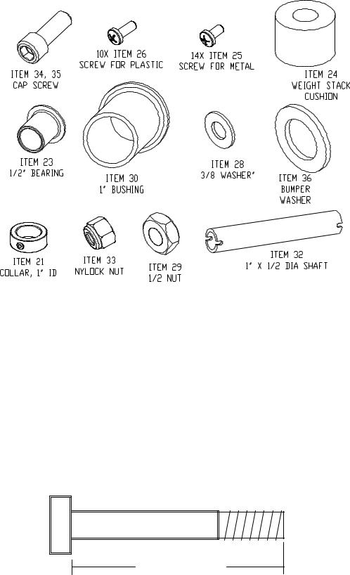
HARDWARE:
REQUIRED TOOLS:
*9/16” wrench
*Ratchet and 9/16” socket
*Adjustable wrench
*Tape measure
*Two 5/16”Allen wrenches
*4 mmAllen wrench
*3/4 Wrench
*Phillups Screw Driver
BOLT LENGTH
|
1/2 |
|
1/2 |
|
1/2 |
|
1/2 |
|
1/2 |
|
|
1/2 |
|
|||||||||||
0 |
|
|
1 |
|
|
2 |
|
|
3 |
|
|
4 |
|
|
5 |
|
6 |
|||||||
|
|
|
|
|
|
|
|
|
|
|
|
|
|
|
|
|
|
|
|
|
|
|
|
|
6
SECURLEY TIGHTEN |
3/8 x 3/4 |
3/8 x 1” |
3/8 x 3-1/2 |
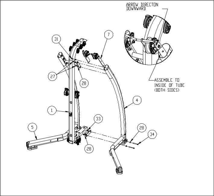
FIGURE 1 |
STEP 1:
LOOSELY assemble bottom of the LEFT UPRIGHT (4) and RIGHT UPRIGHT (5) to FRONT UPRIGHT (1) using four 3/8 x 3-1/2 BOLTS (34), eight 3/8 WASHERS (28) and four 3/8 NUTS (33) and TOP PULLEYS (7)
LOOSELY assemble the top of the LEFT UPRIGHT (4) and RIGHT UPRIGHT (5) to FRONT UPRIGHT (1) and TOP PULLEYS (7), using four 3/8 x 1” BOLTS (27) for bottom four holes, two 3/8 x 3/4 BOLTS (31) for top two holes and six 3/8 WASHERS (28) as illustrated in FIGURE 1.
SECURLEY TIGHTEN ONLY THE UPPER TWO 3/8 X 3/4” BOLTS
NOTE:
THE TOP PULLEY WELDMENT ATTACHES TO THE INSIDE OF THE UPRIGHT SIDES AND THE ORIENTATION SHOULD BE SO THE ARROW POINTS FORWARD AS SHOWN
|
1/2 |
|
|
1/2 |
|
|
1/2 |
|
|
1/2 |
|
1/2 |
|
|
1/2 |
|
||||||||
0 |
|
|
1 |
|
2 |
|
3 |
|
|
4 |
|
|
5 |
|
6 |
|||||||||
|
|
|
|
|
|
|
|
|
|
|
|
|
|
|
|
|
|
|
|
|
|
|
|
|
7
 Loading...