


660 GYM SYSTEM
WARNING:
Read and follow all directions for each step to insure proper assembly of this product.
USER’S GUIDE
CLASS H |
1 |
Version: 660101 |
PART # 7034501 |
|
Revision: 06/21/01 |
REV. C |
|
|

TABLE OF CONTENTS
Safety Statement |
.............2 |
General Notes.................. |
3 |
Tools Required................ |
3 |
Gym Layout..................... |
4 |
Parts list.......................... |
5 |
Assembly Instructions..... |
6-48 |
General Maintenance....... |
49 |
Warranty Statement.......... |
50 |
Product Services.............. |
51 |
Insert-Registration Card |
|
IMPORTANT SAFETY INFORMATION
THERE IS A RISK ASSUMED BY INDIVIDUALS WHO USE THIS TYPE OF
EQUIPMENT. TO MINIMIZE RISK FOLLOW THESE RULES!
1.Before using, read all the warnings and instructions on the use of this machine. Use only for intended exercise. DO NOT modify the machine.
2.Obtain a medical exam before beginning any exercise program.
3.Keep body and clothing free of all moving objects.
4.Inspect the machine before use. DO NOT use it if it appears damaged. DO NOT attempt to fix a broken or
jammed machine. Notify your authorized ParaBody dealer before use and have repairs made by an authorized service technician.
5. Be certain that weight pin is completely inserted. Use only the pin provided by the manufacturer. If unsure, call your authorized ParaBody dealer.
6. Never pin the weights or prop plate into an elevated position. DO NOT use the machine if found in this condition. DO NOT attempt to fix. Notify your authorized ParaBody dealer.
7. Inspect cables and their connections before using machine. Pay particular attention to the cable ends. DO NOT attempt to fix. Notify your authorized ParaBody dealer before use and have repairs made by an authorized service technician.
8.Make sure all spring loaded pull pins are fully engaged in the adjustment position and fully tighten thumbscrew before use.
9.Children must not be allowed near this machine. Supervise teenagers.
.
NOTE: In a continual effort to improve our products, specifications are subject to change © 2001 LifeFitness, a division of Brunswick Corporation. All rights reserved. ParaBody is a trademark of Brunswick Corporation
www.parabody.com
2
IMPORTANT NOTES
Please note:
*Thank you for purchasing the ParaBody 660 Gym System. Please read these instructions thoroughly and keep them for future reference.
*This product must be assembled on a flat, level surface to assure its proper function. DO NOT securely tighten any frame connections until the entire frame has been assembled, unless otherwise stated.
Tools Required for Assembly
*Rubber mallet or hammer
*3/4” wrench
*9/16” wrench
*Ratchet with 3/4” and 9/16” sockets
*5/32”, 7/32”, 5/16” Allen wrench
*Adjustable wrench
*Tape measure
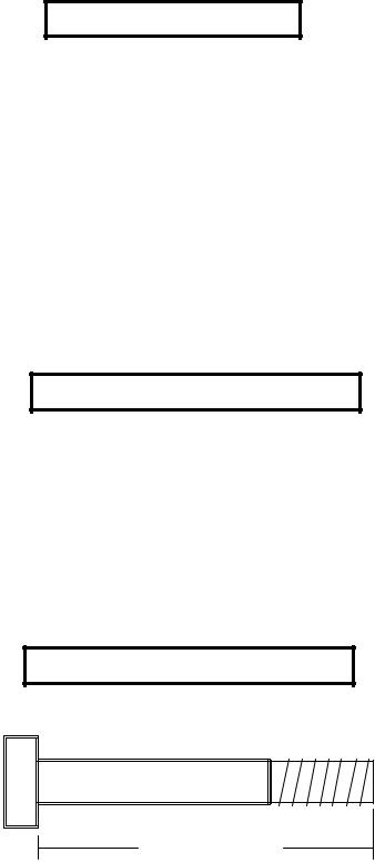
Bolt Length Ruler
NOTE: BOLT LENGTH IS MEASURED FROM THE UNDERSIDE OF THE HEAD OF THE BOLT.
BOLT LENGTH
BOLT LENGTH RULER:
|
1/2 |
|
1/2 |
|
1/2 |
|
1/2 |
|
1/2 |
|
|
1/2 |
|
|||||||||||
0 |
|
|
1 |
|
|
2 |
|
|
3 |
|
|
4 |
|
|
5 |
|
6 |
|||||||
|
|
|
|
|
|
|
|
|
|
|
|
|
|
|
|
|
|
|
|
|
|
|
|
|
3
1’ |
2’ |
3’ |
4’ |
5’ |
6’ |
7’ |
8’ |
9’ |
1’ |
|
|
|
|
|
|
|
|
2’ |
|
|
|
|
|
|
|
|
3’ |
|
|
|
|
|
|
|
|
4’ |
|
|
|
|
|
|
|
|
5’ |
|
|
|
|
|
|
|
|
6’ |
|
|
|
|
|
|
|
|
7’ |
|
|
|
|
|
|
|
|
8’ |
|
|
|
|
|
|
|
|
9’ |
|
|
|
|
|
|
|
|
|
|
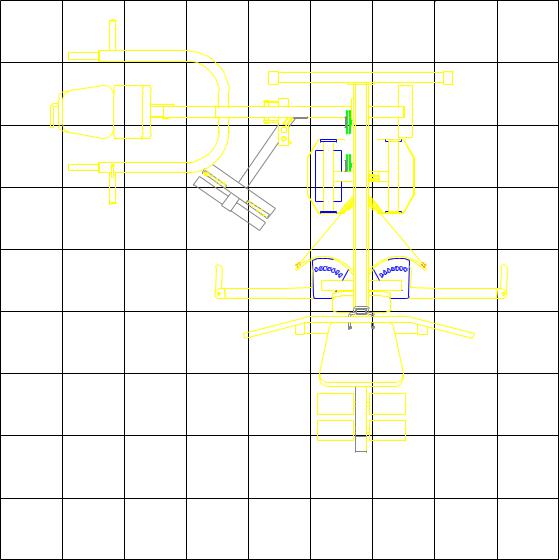
1 Square = 1’ X 1’ |
|
|
|
|
||
|
|
|
|
4 |
|
|
|
|

PARTS LIST
KEY |
PART # |
DESCRIPTION |
QTY |
1 |
6732608 |
BASE |
1 |
2 |
7041908 |
CALF/LOW ROW |
1 |
3 |
6726902 |
COUNTER LEVER |
1 |
4 |
6732708 |
REAR UPRIGHT |
1 |
5 |
6732402 |
PEC SEAT |
1 |
6 |
7042008 |
BEARING HOUSING |
1 |
7 |
6725902 |
D-RING |
1 |
8 |
6723808 |
MIDDLE UPRIGHT |
1 |
9 |
6731602 |
PEC SEATADJUST |
1 |
10 |
6733502 |
PRESS SWIVEL |
1 |
11 |
6732202 |
ROLLER PAD ADJUST |
1 |
12 |
6733402 |
PRESS SEATADJUST |
1 |
13 |
6732308 |
RECEIVING TUBE |
1 |
14 |
6732508 |
TOMALOCK HANDLE |
2 |
15 |
6731508 |
LEG CURL/EXT |
1 |
16 |
6726702 |
BACK PAD ADJUST |
1 |
17 |
7042108 |
TOP BOOM |
1 |
18 |
6737808 |
PRESS BASE |
1 |
19 |
6731308 |
PEC ARM LEFT |
1 |
20 |
6731208 |
PEC ARM RIGHT |
1 |
21 |
6723208 |
PRESS SUPPORT TUBE |
1 |
22 |
6725502 |
PRESS ADJUST TUBE |
1 |
23 |
6731408 |
PRESS BACK SUPPORT |
1 |
24 |
6736702 |
PEC CAM |
2 |
25 |
6733308 |
FRONT UPRIGHT |
1 |
26 |
6723902 |
CENTER PULLEY BRACKET |
1 |
27 |
6737508 |
PRESS ARM |
1 |
28 |
6540202 |
LAT BAR |
1 |
29 |
6686802 |
PULLEY BRACKET |
1 |
30 |
6539102 |
SWIVEL PULLEY |
1 |
31 |
6726501 |
SHROUD |
2 |
32 |
7041601 |
660 SHROUD LABEL |
1 |
33 |
6489902 |
1/4 X 2 X 7-1/4” PLATE |
2 |
34 |
7012102 |
WEIGHT STACK SPACER |
2 |
35 |
6125101 |
3/4 OD X 16” TUBE |
1 |
36 |
6523401 |
72-3/8” GUIDE ROD |
2 |
37 |
6194601 |
ROLLER PAD 4 X 7 |
6 |
38 |
6654721 |
PRESS SEAT PAD |
1 |
39 |
6654321 |
PRESS BACK PAD |
1 |
40 |
6726421 |
PEC BACK PAD |
1 |
41 |
6726221 |
PEC SEAT PAD |
1 |
42 |
3116201 |
3-1/2” PULLEY |
9 |
43 |
3116101 |
4-1/2” PULLEY |
9 |
44 |
6166701 |
2-7/8” L BRACKET |
3 |
45 |
6533501 |
2-3/8” L BRACKET |
3 |
46 |
6405201 |
2” SQ. END CAP |
2 |
47 |
3118401 |
4” VINYL CAP |
1 |
48 |
3106803 |
5/16” SET SCREW |
4 |
49 |
6480301 |
3/8” FLANGE SPACER |
10 |
50 |
3105401 |
3/4" STARLOCK COLLAR |
7 |
51 |
6412001 |
3/8” SPRING PIN ASSEMBLY |
6 |
52 |
6466901 |
1/2” SPRING PIN ASSEMBLY |
1 |
53 |
6140701 |
1 X 1” GLIDE |
6 |
54 |
3103801 |
5/16” SNAP LINK |
4 |
55 |
3117401 |
CAP PLUG |
4 |
56 |
3117901 |
E-RING |
1 |
|
|
|
|
KEY |
PART # |
DESCRIPTION |
QTY |
57 |
3226301 |
JOINT CONNECTOR CAP |
2 |
58 |
3119201 |
8-32 X 3/16” SCREW |
2 |
59 |
3114407 |
#10 FLAT WASHER |
2 |
60 |
6321202 |
CONTROL LEVER |
1 |
61 |
6145801 |
3-PRONG KNOB |
3 |
62 |
6416601 |
PARAGLIDE |
1 |
63 |
6535501 |
3" WHEELS |
2 |
64 |
3203401 |
3/8 X 2-3/4” SOCKET HD SCREW |
2 |
65 |
6177001 |
2-1/2 X 5-1/2” NONSKID STRIP |
2 |
66 |
6427101 |
KEYHOLE CLEVIS |
3 |
67 |
6271801 |
72” ELASTIC CORD |
3 |
68 |
3201501 |
SWIVEL SNAP |
3 |
69 |
3118701 |
2” PULLEY |
3 |
70 |
3108002 |
WEIGHT STACK CUSHION |
2 |
71 |
3102503 |
3/4" WASHER |
2 |
72 |
6953702 |
HEAD PLATE |
1 |
73 |
7095701 |
15 HOLE SELECTOR SHAFT |
1 |
74 |
6075906 |
12 LINK CHAIN |
1 |
75 |
6972201 |
WEIGHT STACK PIN |
1 |
76 |
3104901 |
3/4” FLANGE BEARING |
8 |
77 |
6619501 |
3/4” SLEEVE BEARING |
2 |
78 |
6020601 |
1/2” FLANGE BEARING |
8 |
79 |
6382301 |
PLATE BUSHING 10 CT. |
3 |
80 |
6389701 |
CHROME LOW ROW BAR |
1 |
81 |
6409101 |
ANKLE STRAP |
1 |
82 |
6375801 |
AB CRUNCH STRAP |
1 |
83 |
3102901 |
3/8 X 1-1/4” BOLT |
5 |
84 |
3102933 |
3/8 X 2” BOLT |
9 |
85 |
3102922 |
3/8 X 2-3/4” BOLT |
16 |
86 |
3102902 |
3/8 X 2-1/4” BOLT |
3 |
87 |
3102910 |
1/2 X 3” BOLT |
11 |
88 |
3102917 |
1/2 X 4” BOLT |
8 |
89 |
3102937 |
1/2 X 4-1/2” BOLT |
3 |
90 |
3102943 |
1/2 X 3-1/2” BOLT |
4 |
91 |
3102501 |
3/8” WASHER |
41 |
92 |
3102802 |
3/8” LOCKNUT |
31 |
93 |
3102502 |
1/2” WASHER |
18 |
94 |
3102801 |
1/2” LOCKNUT |
16 |
95 |
3102804 |
1/2” LOW HT LOCKNUT |
10 |
96 |
3202401 |
3/8” BUTTON HD CAP SCREW |
11 |
97 |
3104301 |
3/4” SQ. RUBBER BUMPER |
1 |
98 |
6535601 |
PEC DEC CABLE |
1 |
99 |
6724801 |
LAT CABLE |
1 |
100 |
6724901 |
PRESS CABLE |
1 |
101 |
6724701 |
LEG EXT CABLE |
1 |
102 |
7041801 |
HEAD PLATE CABLE |
1 |
103 |
6725101 |
AB CABLE |
1 |
104 |
6978101 |
WEIGHT STACK LABELS |
1 |
105 |
6939202 |
WEIGHT PLATE |
15 |
106 |
6535001 |
3/8 X 4” THREADED SHAFT |
3 |
107 |
6690901 |
3/4 X 11” SHAFT |
2 |
108 |
3102701 |
3/8” HEX NUT |
8 |
109 |
6122702 |
3/8 X 1/2” SPACER |
4 |
110 |
6866601 |
BOLT COVER |
2 |
111 |
6866801 |
BOLT COVER WASHER |
2 |
112 |
3221702 |
3/4” E-RING |
1 |
|
|
|
|
5
|
|
|
42 |
|
|
|
|
|
|
78 |
90 1/2 X 3-1/2” |
|
|
|
|
|
|
|
|
|
92 |
91 |
|
|
3/8 X 2” 84 |
|
|
|
|
|
|
|
||
|
|
|
91 |
|
|
|
|
|
|
|
|
|
|
|
|
30 |
|
|
92 |
|
|
|
|
|
|
91 |
|
|
|
78 |
|
|
|
42 |
|
|
|
|
|
45 |
|
|
|
|
|
|
|
|
|
|
|
|
|
|
91 |
|
|
|
|
LOW HT. |
92 |
3/8 X 2” 84 |
1/2 X 3” |
87 |
|
|
95 |
||
|
|
91 |
|
|||
|
|
93 |
|
|
43 |
|
|
|
|
|
|
|
|
|
|
|
|
91 |
|
|
|
|
18 |
|
84 |
3/8 X 2” |
|
|
|
|
|
94 |
|
|
|
|
|
|
|
|
|
|
|
|
|
|
2 |
|
|
|
|
|
|
65 |
|
FIGURE 1 |
|
|
|
|
|
|
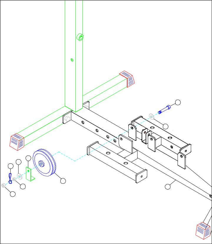
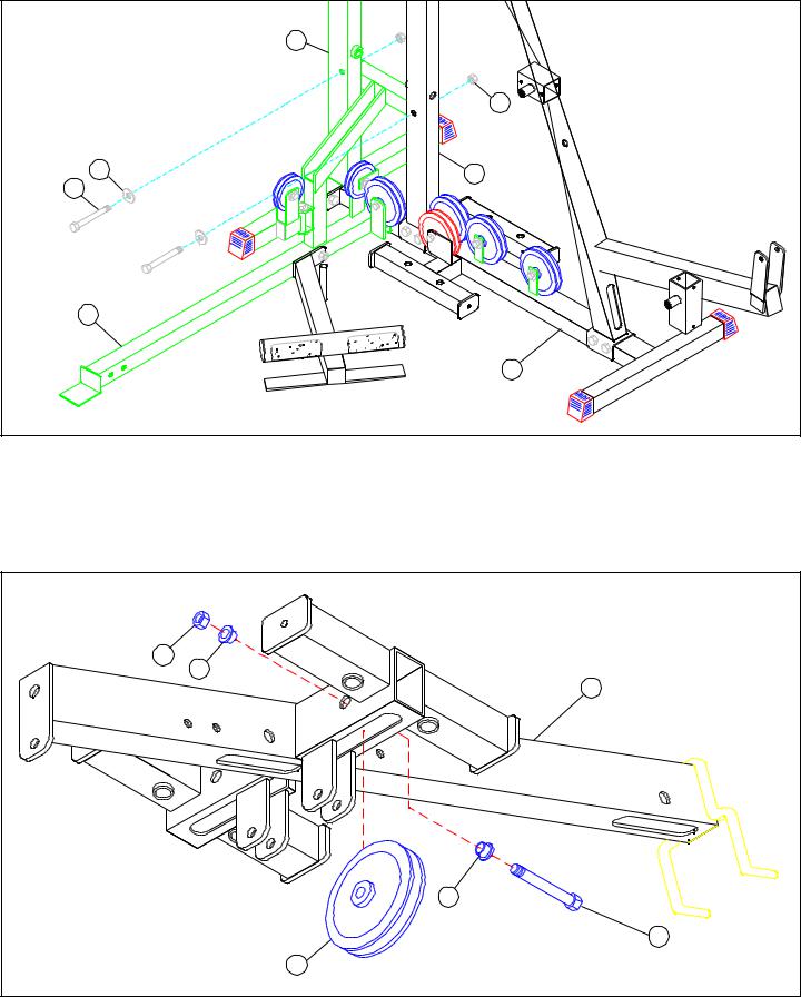
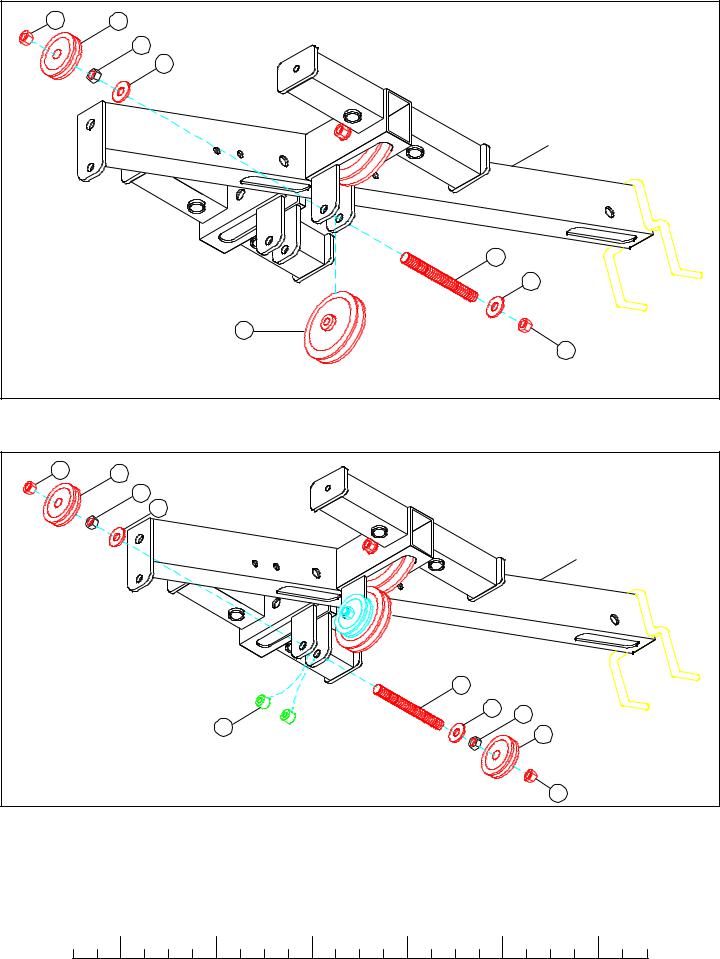
STEP 1
•Insert two 1/2" FLANGE BEARINGS (78) into the SWIVEL PULLEY BRACKET (30) as in FIGURE 1.
•Assemble the SWIVEL PULLEY BRACKET (30) to the PRESS BASE (18) using one 1/2 X 3-1/2" BOLT (90) and one 1/2” LOW HEIGHT LOCK NUT (95). (TIGHTEN THE CONNECTION ENOUGH TO REMOVE THE PLAY, YET ALLOWING THE
SWIVELBRACKET TO ROTATE FREELY.)
•SECURELY assemble one 3-1/2” PULLEY (42) to the SWIVEL PULLEY BRACKET (30) using one 3/8 X 2" BOLT (84), two 3/ 8” WASHERS (91), and one 3/8” LOCK NUT (92). See FIGURE 1.
•SECURELY assemble one 3-1/2" PULLEY (42) to the rear horizontal flat of the PRESS BASE (18) using one 3/8 X 2" BOLT (84), one 2-3/8" CABLE RETAINING CLIP (45), two 3/8" WASHERS (91), and one 3/8" LOCK NUT (92) as shown in FIGURE 1. (NOTE: 2-3/8” CABLE RETAINING CLIP (45) should face as shown in FIGURE 1.)
•SECURELY assemble one 4-1/2" PULLEY (43) to the lower horizontal flat of the PRESS BASE (18) using one 3/8 X 2" BOLT (84), two 3/8" WASHERS (91), and one 3/8" LOCK NUT (92) as shown in FIGURE 1. (NOTE: Make sure there is no contact between the two pulleys.)
•Attach two 5-1/2 X 2-1/2" NON SKID STRIPS (65) to the LOW ROW/CALF RAISE (2) approximately where shown in FIGURE 1.
•SECURELY assemble the LOW ROW/CALF RAISE (2) to the PRESS BASE (18) using two 1/2 X 3" BOLTS (87), two 1/2" WASHERS (93), and one 1/2" LOCK NUT (94).
6
4 |
94 |
93 |
87 1/2 X 3” |
1 |
FIGURE 2 |
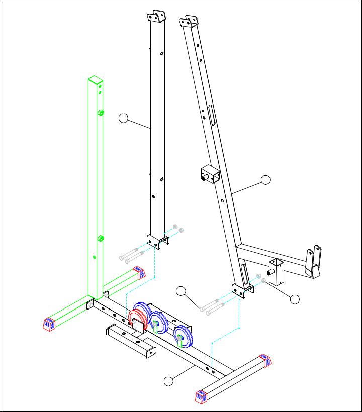
STEP 2
•LOOSELY assemble the REAR UPRIGHT (4) to the BASE (1) using two 1/2 X 3” BOLTS (87), two 1/2” WASHERS (93), and two 1/2” LOCK NUTS (94) as shown in FIGURE 2.
|
1/2 |
|
1/2 |
|
1/2 |
|
1/2 |
|
1/2 |
|
|
1/2 |
0 |
1 |
2 |
3 |
4 |
5 |
6 |
||||||
7
|
86 3/8 X 2-1/4” |
|
91 |
44 |
|
91 |
|
68 |
|
|
43 |
108 HEXNUT |
1 |
92 |
|
FIGURE 3 |
|
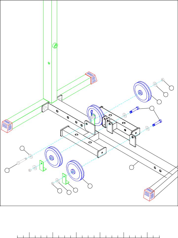
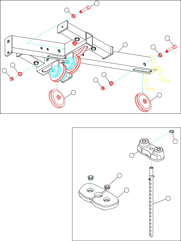
STEP 3
•SECURELYassemble one 4-1/2” PULLEY (43) to the upper flat on the BASE (1) using one 3/8 X 2-1/4” BOLT (86), two 3/8” WASHERS (91), one 2-7/8” L-BRACKET (44), one 3/8” HEX NUT (108), one SWIVEL SNAP (68) and one 3/8” LOCK NUT (92). See FIGURE 3.
8
|
|
92 |
|
|
91 |
|
|
43 |
|
|
84 3/8 X 2” |
91 |
|
|
86 3/8 X 2” |
|
1 |
|
|
|
|
|
43 |
92 |
91 |
44 |
|
|
|
FIGURE 4 |
|
|
STEP 4
•SECURELYassemble three 4-1/2” PULLEYS (43) to the flats on the BASE (1) using three 3/8 X 2” BOLTS (84), six 3/8” WASHERS (91), two 2-7/8” L-BRACKETS (44), and three 3/8” LOCK NUTS (92). See FIGURE 4.
|
1/2 |
|
1/2 |
|
1/2 |
|
1/2 |
|
1/2 |
|
|
1/2 |
0 |
1 |
2 |
3 |
4 |
5 |
6 |
||||||
9
8 |
|
|
25 |
1/2 X 4” |
88 |
|
94 |
1 |
|
FIGURE 5 |
|
STEP 5
•LOOSELY assemble the FRONT (25) & MIDDLE UPRIGHTS (8) to the BASE (1) using four 1/2 X 4” BOLTS (88) and four 1/2” LOCK NUTS (94) as shown in FIGURE 5.
10
|
88 1/2 X 4” |
|
93 |
|
1 |
18 |
94 |
|
|
FIGURE 6 |
|
STEP 5
•LOOSELY assemble the PRESS BASE (18) to the BASE (1) using two 1/2 X 4” BOLTS (88), two 1/2” WASHERS (93), and two 1/2” LOCK NUTS (94). See FIGURE 6.
|
1/2 |
|
1/2 |
|
1/2 |
|
1/2 |
|
1/2 |
|
|
1/2 |
0 |
1 |
2 |
3 |
4 |
5 |
6 |
||||||
11
|
4 |
|
94 |
93 |
8 |
1/2 X 3” 87 |
|
18 |
|
|
1 |
FIGURE 7 |
|
STEP 7
•LOOSELY assemble the PRESS BASE (18) to the REAR (4) & MIDDLE UPRIGHTS (8) using two 1/2 X 3” BOLTS (87), two 1/2” WASHERS (93), and two 1/2” LOCK NUTS (94). See FIGURE 7.
|
92 |
|
49 |
|
17 |
|
49 |
|
85 3/8 X 2-3/4” |
FIGURE 8 |
43 |
|
STEP 8
•LOOSELY assemble one 4-1/2” PULLEY (43) to the TOP BOOM (17) using one 3/8 X 2-3/4” BOLT (85), two 3/8” FLANGE SPACERS (49), and one 3/8” LOCK NUT (92). See FIGURE 8.
12
92 |
69 |
|
108108 3/8” HEX NUT |
|
91 |
|
TOP BOOM |
|
106 |
|
91 |
|
42 |
|
92 |
FIGURE 9 |
|
STEP 8
•SECURELY assemble one 3-1/2” PULLEY (42) to the bracket on the TOP BOOM using one 3/8” THREADED SHAFT (106) , two 3/8” WASHERS (91), one 2” PULLEY (69), one 3/8” HEX NUT (108) and two 3/8” LOCK NUTS (92). See FIGURE 9.
92 |
69 |
|
|
108108 3/8” HEX NUT |
|
|
91 |
|
|
|
TOP BOOM |
|
106 |
|
|
91 |
108108 3/8” HEX NUT |
|
109 |
69 |
|
|
|
FIGURE 10 |
92 |
|
STEP 10
•Position two 3/8 X 1/2” SPACERS (109) inside the rear bracket of the TOP BOOM and slide one 3/8” THREAD SHAFT (106) through the bracket. See FIGURE 10.
•SECURELY assemble two 2” PULLEYS (69) to the rear bracket on the TOP BOOM using the 3/8” THREADED SHAFT (106), two 3/8” WASHERS (91), two 3/8” HEX NUTS (108), and two 3/8” LOCK NUTS (92) as shown in FIGURE 10.
|
1/2 |
|
1/2 |
|
1/2 |
|
1/2 |
|
1/2 |
|
|
1/2 |
0 |
1 |
2 |
3 |
4 |
5 |
6 |
||||||
13
|
85 3/8 X 2-3/4” |
|
49 |
|
|
|
|
3/8 X 2-3/4” 85 |
|
17 |
49 |
|
|
|
49 |
|
|
92 |
49 |
|
|
|
|
|
92 |
|
42 |
|
42 |
|
|
|
FIGURE 11 |
|
|
STEP11
•LOOSELYassemble two 3-1/2” PULLEYS (42) to theTOP BOOM (17) using two 3/8 X 2-3/4” BOLTS (85), four 3/8” FLANGE SPACERS (49), and two 3/8” LOCK NUTS (92). See FIGURE 11.
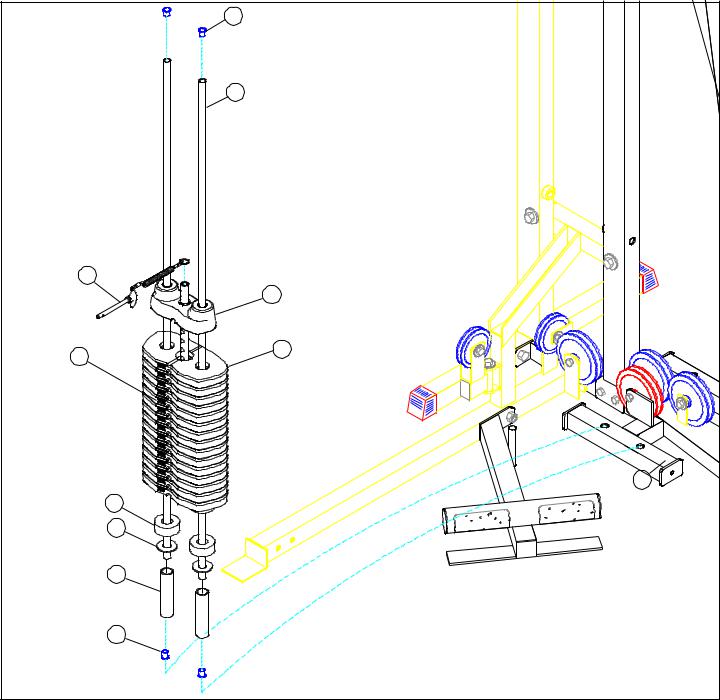
STEP 12
•Snap two WEIGHT PLATE BUSHINGS (79) each, into the “ top” side of fifteen WEIGHT PLATES
(105)as shown in FIGURE 12.
•Slide the WEIGHT PLATE SHAFT (73) thru the hole in the HEAD PLATE(72), and lock in place using one 3/4” E-RING (112) as shown in FIGURE 12.
FIGURE 12 |
112 |
72 |
79 |
105 |
73 |
14 |
|
55 |
|
36 |
75 |
|
|
72 |
104 |
105 |
|
|
|
1 |
70 |
|
71 |
|
34 |
|
55 |
|
FIGURE 13 |
|
STEP 13
•Insert four CAP PLUGS (55) into the top and bottom ends of the GUIDE RODS (36) as shown in FIGURE 13.
•Insert two GUIDE RODS (36) into the BASE (1) as shown on FIGURE 13. (NOTE: Lubricate GUIDE RODS (36) with silicon or teflon spray available at most hardware stores.)
•Slide two WEIGHT STACK SPACERS (34), two 3/4” WASHERS (71), and two WEIGHT STACK CUSHIONS (70) - IN THAT ORDER - down over the GUIDE RODS (36).
•Using EXTREME CARE slide all fifteen WEIGHT PLATES (105) down over the GUIDE RODS (36) on to the WEIGHT STACK CUSHIONS (70). Make sure that the keyholes of the WEIGHT PLATES (105) are all facing the right way. (NOTE: If the 216101
50 LB. ADD-KIT is purchased refer to the 216101 ASSEMBLY INSTRUCTIONS now.)
•Slide the head plate assembly down over the GUIDE RODS (36) onto the weight stack.
•Attach the WEIGHT STACK LABELS (104) to the weight stack. Also insert the WEIGHT STACK PIN (75) into the first WEIGHT PLATE (105) of the weight stack.
15
92 |
92 |
|
17 |
85 3/8 X 2-3/4” |
|
85 3/8 X 2-3/4” |
|
|
25 |
|
8 |
FIGURE 14
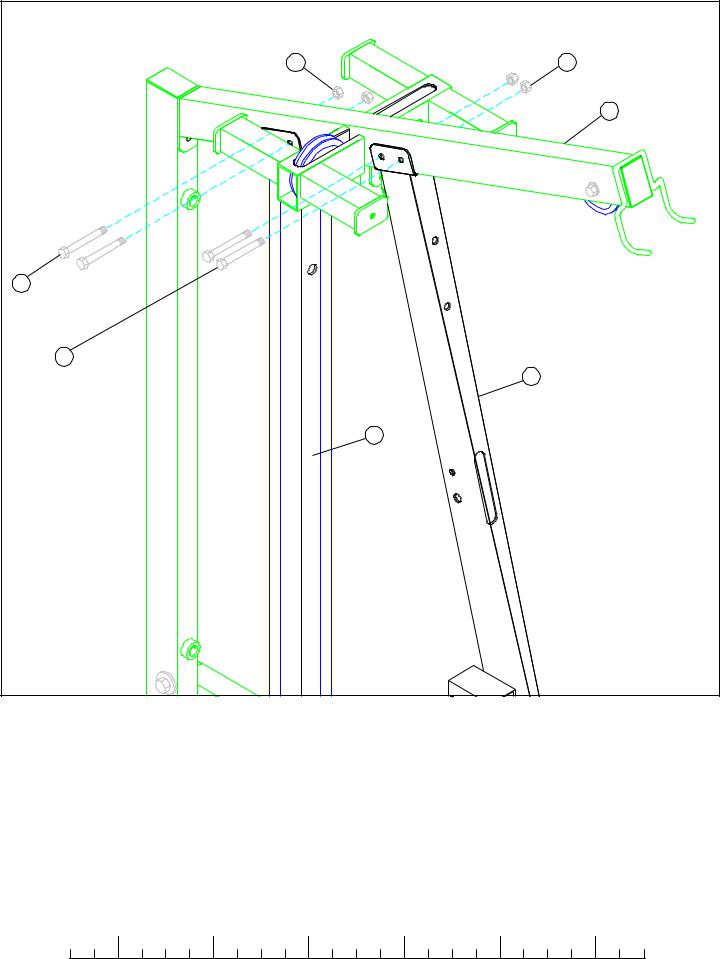
STEP 14
•LOOSELY assemble the TOP BOOM (17) to the top of the MIDDLE (8) & FRONT UPRIGHT (25) using four 3/8 X 2-3/4” BOLTS (85) and four 3/8” LOCK NUTS (92). See FIGURE 14.
|
1/2 |
|
1/2 |
|
1/2 |
|
1/2 |
|
1/2 |
|
|
1/2 |
0 |
1 |
2 |
3 |
4 |
5 |
6 |
||||||
16
 Loading...