


95R Recumbent Lifecycle® Exercise Bike
Assembly Instructions

Congratulations...
and welcome to the world of
The following Parts List and the step-by-step assembly procedures have been assembled to make the set-up of the Recumbent Lifecycle® Exercise Bike as quick and easy as possible.
Please take special note of the following important points prior to choosing a location and beginning assembly of the Recumbent Lifecycle® Exercise Bike.
IMPORTANT SAFETY INSTRUCTIONS !
DO NOT locate the Exercise Bike outdoors, near swimming pools, or in areas of high humidity.
DO NOT operate your Exercise Bike if it has been dropped, damaged, or even partially immersed in water. Contact Life Fitness Customer Support Services at the number in the
Operation Manual.
DO NOT locate the Exercise Bike any closer than 30 inches ( 76 cm ) to a television set.
DO NOT locate additional Exercise Bike any closer than a minimum of 42 inches (107 cm) from center to center to avoid interference (cross talk) between Heart Rate monitors.
DO keep the area around your Exercise Bike clear of any obstructions, including walls and furniture.
DO verify the contents of the delivery carton against the accompanying Parts Listing prior to setting the cartons and shipping material aside. If any parts are missing, contact Life Fitness Customer Support Services at the number listed in the Operation Manual. Save the shipping cartons in case of return.
DO read the entire Operation Manual prior to attempting to operate this machine as this is essential for proper use.
CONSIGNES DE SECURITE IMPORTANTES!
NE PAS placer le vélo d'exercice allongé Lifecycle à l'extérieur, près d'une piscine ou dans un endroit très humide.
NE PAS faire fonctionner le vélo d'exercice allongé Lifecycle s'il est tombé, s'il a été endommagé ou s'il a été partiellement plongé dans l'eau. Téléphoner au service après-vente de Life Fitness dont le numéro figure sur la couverture arrière du guide d'installation.
NE PAS placer le vélo d'exercice allongé Lifecycle à moins de 76 cm (30 po) d'un poste de télévision.
MAINTENIR la zone autour du vélo d'exercice allongé Lifecycle libre de toute obstruction, y compris murs et meubles.
VÉRIFIER si l'emballage contient toutes les pièces de la liste jointe avant de le mettre de côté.
Si des pièces manquent, téléphoner au service après-vente de Life Fitness dont le numéro figure sur la couverture arrière du guide d'installation. Conserver l'emballage au cas où l'appareil devrait être renvoyé.
LIRE le manuel de l'utilisateur tout entier avant d'essayer de faire fonctionner cet appareil. Ceci est indispensable à son utilisation correcte.
TOOLS REQUIRED FOR ASSEMBLY...
Magnetic #2 Bit Phillips Screwdriver, 6mm Hex Key Allen Driver and Ratchet, Side Cutters, 17mm socket and Ratchet
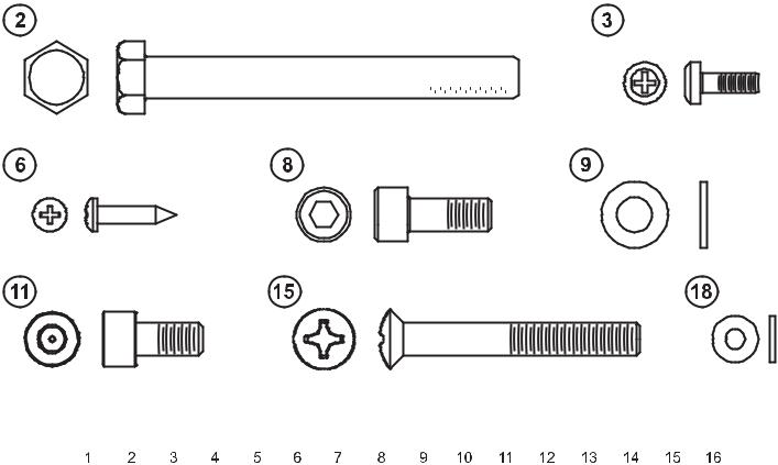
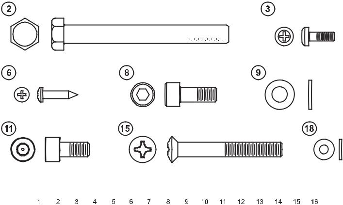
PARTS DESCRIPTION
1 |
Monocolumn Assembly |
|
|
|
Qty: |
1 |
|
|
2 |
|
|
M10 X 90MM Screw |
|
|
|
|
|
Qty: |
3 |
|||||||||||||||||||||||||||||||||||||||||||||||||||||||||||||
|
|
|
|
|
|
|
|
|
|
|
|
|
|
|
|
|
|
|
|
|
|
|
|
|
|
|
|
|
|
|
|
|
|
|
|
|
|
|
|
0017-00101-2035 |
|
|
|
|
|
|
|
|
|
|
|
|
|
|
|
|
|
|
|
|
|
|
||||||||||||||||||
|
|
|
|
|
|
|
|
|
|
|
|
|
|
|
|
|
|
|
|
|
|
|
|
|
|
|
|
|
|
|
|
|
|
|
|
|
|
|
|
|
|
|
|
|
|
|
|
|
|
|
|
|
|
|
|
|
|
|
|
|
|
|
|
|
|
|
|
|
|
|
|
|
|
|
|
|
|
|
|
|
3 |
Phillips Screw |
|
|
|
Qty: |
1 |
|
|
4 |
|
|
Display Console |
|
|
|
|
|
Qty: |
1 |
|||||||||||||||||||||||||||||||||||||||||||||||||||||||||||||
|
0017-00101-1796 |
|
|
|
|
|
|
|
|
|
|
|
|
|
|
|
|
|
|
|
|
|
|
|
|
|
|
|
|
|
|
|
|
|
|
|
|
|
|
|
|
|
|
|
|
|
|
|
|
|
|
|
|
|
|
|
|
|
|
|
|
|
|
|
|
|
|
|
|
|
|
|
||||||||
5 |
Rear Cover |
|
|
|
Qty: |
1 |
|
|
6 |
|
|
M5 x 14mm Phillips Screw |
|
|
|
|
|
Qty: |
4 |
|||||||||||||||||||||||||||||||||||||||||||||||||||||||||||||
|
|
|
|
|
|
|
|
|
|
|
|
|
|
|
|
|
|
|
|
|
|
|
|
|
|
|
|
|
|
|
|
|
|
|
|
|
|
|
|
0017-00101-1940 |
|
|
|
|
|
|
|
|
|
|
|
|
|
|
|
|
|
|
|
|
|
|
||||||||||||||||||
|
|
|
|
|
|
|
|
|
|
|
|
|
|
|
|
|
|
|
|
|
|
|
|
|
|
|
|
|
|
|
|
|
|
|
|
|
|
|
|
|
|
|
|
|
|
|
|
|
|
|
|
|
|
|
|
|
|
|
|
|
|
|
|
|
|
|
|
|
|
|
|
|
|
|
|
|
|
|
|
|
7 |
Handlebar |
|
|
|
Qty: |
1 |
|
|
8 |
|
|
M8 X 20MM Screw |
|
|
|
|
|
Qty: |
8 |
|||||||||||||||||||||||||||||||||||||||||||||||||||||||||||||
|
|
|
|
|
|
|
|
|
|
|
|
|
|
|
|
|
|
|
|
|
|
|
|
|
|
|
|
|
|
|
|
|
|
|
|
|
|
|
|
0017-00101-1881 |
|
|
|
|
|
|
|
|
|
|
|
|
|
|
|
|
|
|
|
|
|
|
||||||||||||||||||
9 |
M8 Washer |
|
|
|
Qty: |
10 |
|
10 |
|
Accessory Tray Holder |
|
|
|
|
|
Qty: |
1 |
|||||||||||||||||||||||||||||||||||||||||||||||||||||||||||||||
|
0017-00104-0469 |
|
|
|
|
|
|
|
|
|
|
|
|
|
|
|
|
|
|
|
|
|
|
|
|
|
|
|
|
|
|
|
|
|
|
|
|
|
|
|
|
|
|
|
|
|
|
|
|
|
|
|
|
|
|
|
|
|
|
|
|
|
|
|
|
|
|
|
|
|
|
|
||||||||
|
|
|
|
|
|
|
|
|
|
|
|
|
|
|
|
|
|
|
|
|
|
|
|
|
|
|
|
|
|
|
|
|
|
|
|
|
|
|
|
|
|
|
|
|
|
|
|
|
|
|
|
|
|
|
|
|
|
|
|
|
|
|
|
|
|
|
|
|
|
|
|
|
|
|
|
|
|
|
|
|
11 |
M8 X 16MM Screw |
|
|
|
Qty: |
2 |
|
|
12 |
|
Seat |
|
|
|
|
|
Qty: |
1 |
||||||||||||||||||||||||||||||||||||||||||||||||||||||||||||||
|
0017-00101-2030 |
|
|
|
|
|
|
|
|
|
|
|
|
|
|
|
|
|
|
|
|
|
|
|
|
|
|
|
|
|
|
|
|
|
|
|
|
|
|
|
|
|
|
|
|
|
|
|
|
|
|
|
|
|
|
|
|
|
|
|
|
|
|
|
|
|
|
|
|
|
|
|
||||||||
13 |
Accessory Tray |
|
|
|
Qty: |
1 |
|
|
14 |
|
Seat Back |
|
|
|
|
|
Qty: |
1 |
||||||||||||||||||||||||||||||||||||||||||||||||||||||||||||||
|
|
|
|
|
|
|
|
|
|
|
|
|
|
|
|
|
|
|
|
|
|
|
|
|
|
|
|
|
|
|
|
|
|
|
|
|
|
|
|
|
|
|
|
|
|
|
|
|
|
|
|
|
|
|
|
|
|
|
|
|
|
|
|
|
|
|
|
|
|
|
|
|
|
|
|
|
|
|
|
|
15 |
M8 X 60MM Screw |
|
|
|
Qty: |
4 |
|
|
16 |
|
Power Block (for Engage Console Only) |
|
|
|
|
|
Qty: |
1 |
||||||||||||||||||||||||||||||||||||||||||||||||||||||||||||||
|
0017-00101-2018 |
|
|
|
|
|
|
|
|
|
|
|
|
|
|
|
|
|
|
|
|
|
|
|
|
|
|
|
|
|
|
|
|
|
|
|
|
|
|
|
|
|
|
|
|
|
|
|
|
|
|
|
|
|
|
|
|
|
|
|
|
|
|
|
|
|
|
|
|
|
|
|
||||||||
17 |
Power Cord (for Engage Console Only) |
|
|
|
Qty: |
1 |
|
|
18 |
|
M5 Washer |
|
|
|
|
|
Qty: |
1 |
||||||||||||||||||||||||||||||||||||||||||||||||||||||||||||||
|
|
|
|
|
|
|
|
|
|
|
|
|
|
|
|
|
|
|
|
|
|
|
|
|
|
|
|
|
|
|
|
|
|
|
|
|
|
|
|
0017-00104-0494 |
|
|
|
|
|
|
|
|
|
|
|
|
|
|
|
|
|
|
|
|
|
|
||||||||||||||||||
|
|
|
|
|
|
|
|
|
|
|
|
|
|
|
|
|
|
|
|
|
|
|
|
|
|
|
|
|
|
|
|
|
|
|
|
|
|
|
|
|
|
|
|
|
|
|
|
|
|
|
|
|
|
|
|
|
|
|
|
|
|
|
|
|
|
|
|
|
|
|
|
|
|
|
|
|
|
|
|
|
19 |
Nut Plate |
|
|
|
Qty: |
1 |
|
|
20 |
|
Two-Hole Plate |
|
|
|
|
|
Qty: |
1 |
||||||||||||||||||||||||||||||||||||||||||||||||||||||||||||||
|
|
|
|
|
|
|
|
|
|
|
|
|
|
|
|
|
|
|
|
|
|
|
|
|
|
|
|
|
|
|
|
|
|
|
|
|
|
|
|
|
|
|
|
|
|
|
|
|
|
|
|
|
|
|
|
|
|
|
|
|
|
|
|
|
|
|
|
|
|
|
|
|
|
|
|
|
|
|
|
|
21 |
One-Hole Plate |
|
|
|
Qty: |
1 |
|
|
|
|
|
|
|
|
|
|
|
|
|
|
|
|
|
|
|
|
|
|
|
|
|
|
|
|
|
|
|
|
|
|
|
|
|
|
|
|
|
|
|
|
|
|
|
|||||||||||||||||||||||||||
|
|
|
|
|
|
|
|
|
|
|
|
|
|
|
|
|
|
|
|
|
|
|
|
|
|
|
|
|
|
|
|
|
|
|
|
|
|
|
|
|
|
|
|
|
|
|
|
|
|
|
|
|
|
|
|
|
|
|
|
|
|
|
|
|
|
|
|
|
|
|
|
|
|
|
|
|
|
|
|
|
|
|
|
|
|
|
|
|
|
|
|
|
|
|
|
|
|
|
|
|
|
|
|
|
|
|
|
|
|
|
|
|
|
|
|
|
|
|
|
|
|
|
|
|
|
|
|
|
|
|
|
|
|
|
|
|
|
|
|
|
|
|
|
|
|
|
|
|
|
|
|
|
|
|
|
|
|
|
|
|
|
|
|
|
|
|
|
|
|
|
|
|
|
|
|
|
|
|
|
|
|
|
|
|
|
|
|
|
|
|
|
|
|
|
|
|
|
|
|
|
|
|
|
|
|
|
|
|
|
|
|
|
|
|
|
|
|
|
|
|
|
|
|
|
|
|
|
|
|
|
|
|
|
|
|
|
|
|
|
|
|
|
|
|
|
|
|
|
|
|
|
|
|
|
|
|
|
|
|
|
|
|
|
|
|
|
|
|
|
|
|
|
|
|
|
|
|
|
|
|
|
|
|
|
|
|
|
|
|
|
|
|
|
|
|
|
|
|
|
|
|
|
|
|
|
|
|
|
|
|
|
|
|
|
|
|
|
|
|
|
|
|
|
|
|
|
|
|
|
|
|
|
|
|
|
|
|
|
|
|
|
|
|
|
|
|
|
|
|
|
|
|
|
|
|
|
|
|
|
|
|
|
|
|
|
|
|
|
|
|
|
|
|
|
|
|
|
|
|
|
|
|
|
|
|
|
|
|
|
|
|
|
|
|
|
|
|
|
|
|
|
|
|
|
|
|
|
|
|
|
|
|
|
|
|
|
|
|
|
|
|
|
|
|
|
|
|
|
|
|
|
|
|
|
|
|
|
|
|
|
|
|
|
|
|
|
|
|
|
|
|
|
|
|
|
|
|
|
|
|
|
|
|
|
|
|
|
|
|
|
|
|
|
|
|
|
|
|
|
|
|
|
|
|
|
|
|
|
|
|
|
|
|
|
|
|
|
|
|
|
|
|
|
|
|
|
|
|
|
|
|
|
|
|
|
|
|
|
|
|
|
|
|
|
|
|
|
|
|
|
|
|
|
|
|
|
|
|
|
|
|
|
|
|
|
|
|
|
|
|
|
|
|
|
|
|
|
|
|
|
|
|
|
|
|
|
|
|
|
|
|
|
|
|
|
|
|
|
|
|
|
|
|
|
|
|
|
|
|
|
|
|
|
|
|
|
|
|
|
|
|
|
|
|
|
|
|
|
|
|
|
|
|
|
|
|
|
|
|
|
|
|
|
|
|
|
|
|
|
|
|
|
|
|
|
|
|
|
|
|
|
|
|
|
|
|
|
|
|
|
|
|
|
|
|
|
|
|
|
|
|
|
|
|
|
|
|
|
|
|
|
|
|
|
|
|
|
|
|
|
|
|
|
|
|
|
|
|
|
|
|
|
|
|
|
|
|
|
|
|
|
|
|
|
|
|
|
|
|
|
|
|
|
|
|
|
|
|
|
|
|
|
|
|
|
|
|
|
|
|
|
|
|
|
|
|
|
|
|
|
|
|
|
|
|
|
|
|
|
|
|
|
|
|
|
|
|
|
|
|
|
|
|
|
|
|
|
|
|
|
|
|
|
|
|
|
|
|
|
|
|
|
|
|
|
|
|
|
|
|
|
|
|
|
|
|
|
|
|
|
|
|
|
|
|
|
|
|
|
|
|
|
|
|
|
|
|
|
|
|
|
|
|
|
|
|
|
|
|
|
|
|
|
|
|
|
|
|
|
|
|
|
|
|
|
|
|
|
|
|
|
|
|
|
|
|
|
|
|
|
|
|
|
|
|
|
|
|
|
|
|
|
|
|
|
|
|
|
|
|
|
|
|
|
|
|
|
|
|
|
|
|
|
|
|
|
|
|
|
|
|
|
|
|
|
|
|
|
|
|
|
|
|
|
|
|
|
|
|
|
|
|
|
|
|
|
|
|
|
|
|
|
|
|
|
|
|
|
|
|
|
|
|
|
|
|
|
|
|
|
|
|
|
|
|
|
|
|
|
|
|
|
|
|
|
|
|
|
|
|
|

IMPORTANT!
DO NOT DISCARD THE SHIP KIT. ALL NECESSARY COMPONENTS NEEDED TO COMPLETE
THE INSTALLATION ARE LOCATED IN THE SHIP KIT.
IMPORTANT!
NE JETEZ PAS LE KIT. IL CONTIENT TOUS LES ÉLÉMENTS NÉCESSAIRES POUR
L'INSTALLATION.
1.Position the unit base near its location for use.
2.Remove the USER LEFT CRANK ARM HOLE PLUG (A) and set it aside. Remove the
USER LEFT CRANK ARM SCREW (B) and slide the CRANK ARM (C) off the unit. Set them both aside.
3.Remove the seven SCREWS (D) securing the USER LEFT FRONT SHROUD (E).
Remove the FRONT SHROUD and set it aside.
4. Slide the MONOCOLUMN ASSEMBLY (1) over the FRONT TUBE (F). Position and align the NUT PLATE (19), TWO-HOLE PLATE (20) and ONE-HOLE PLATE (21) at the front and back of the MONOCOLUMN ASSEMBLY as shown. Secure the MONOCOLUMN ASSEMBLY using three M10 x 90mm SCREWS (2). Tighten the
SCREWS to 50-55 ft lbs.
NOTE: Be careful not to pinch wires when sliding the MONOCOLUMN ASSEMBLY over the FRONT TUBE.
Re-install the USER LEFT FRONT SHROUD (E) using the seven previously removed SCREWS (D).
Re-install the CRANK ARM (C) using the USER LEFT CRANK ARM SCREW (B) previously removed. Tighten
the SCREWS to 30-33 ft lbs. Replace the USER LEFT
CRANK ARM HOLE PLUG (A).
Slide the FRONT ACCESSORY TRAY (G) downward to  meet the FRONT SHROUDS (E). Secure the FRONT ACCESSORY
TRAY using one PHILLIPS SCREW (3) and M5 WASHER (18). Tighten the SCREWS securely. Do not overtighten the SCREWS.
5. Cut the wire tie holding the cables to the CONSOLE BRACKET (H).
Position the DISPLAY CONSOLE (4) near the CONSOLE BRACKET (H). Connect the MAIN CONSOLE CABLE (J), NETWORK CABLE (K) and
GROUND WIRE (L) leading from the MONOCOLUMN ASSEMBLY (1) to their respective locations in the back of the DISPLAY CONSOLE.
NOTE: If using C-SAFE, connect the NETWORK CABLE to the BLACK JACK. If using ETHERNET, connect the NETWORK CABLE to the SILVER JACK.
For units with Engage Consoles (15” LCD)
Connect the COAXIAL CABLE (M) leading from the MONOCOLUMN ASSEMBLY (1) to the back of the DISPLAY CONSOLE.
NOTE: Be sure all CONNECTORS are fully seated.
Bundle and wire-tie unused cables to the side of the CONSOLE BRACKET center post. Do not block any mounting holes.
Rest the DISPLAY CONSOLE on the CONSOLE BRACKET. Position the REAR COVER (5) at the back of the DISPLAY CONSOLE and secure together using four SCREWS (6). Tighten the SCREWS securely. Do not overtighten the SCREWS.

6.Position the HANDLEBARS (7) as shown. Secure each HANDLEBAR to the SEAT FRAME (N) using two M8 x 20mm SCREWS (8) and two M8 WASHERS (9) each.
NOTE: Be sure the the TABS of the HANDLEBARS are inserted into the slots on the underside of the SEAT FRAME as shown in the detail before securing.
Connect the HEART RATE CABLES (O) leading from the HANDLEBARS to the CENTER LEAD (P) located in the SEAT FRAME.
NOTE: Be sure the CONNECTORS are fully seated.
7.Secure the ACCESSORY TRAY HOLDER (10) to the SEAT FRAME (N) using two M8 x 16mm SCREWS (11) and two M8 WASHERS (9). Tighten the SCREWS securely. Do not overtighten the SCREWS.
Secure the SEAT (12) to the SEAT FRAME (N) using four M8 x 20mm SCREWS (8) and two M8 WASHERS (9). Tighten the SCREWS securely. Do not overtighten the SCREWS.
Place the ACCESSORY TRAY (13) into the ACCESSORY TRAY HOLDER as shown. Press down firmly to secure the ACCESSORY TRAY in place.
8.Attach the SEAT BACK (14) to the SEAT FRAME (N) using four SCREWS (15). Tighten the SCREWS securely. Do not overtighten the SCREWS.

9.For units with Engage Consoles
Position the unit in its final position for use.
Remove the protective liner from one of the provided FASTENER STRIPS. Attach the fastener strip to the bottom of the POWER BLOCK (16). Interlock the remaining FASTENER STRIP to the installed FASTENER STRIP. Remove the remaining protective liner from FASTENER STRIP and secure the POWER BLOCK to the underside of the CENTER FRAME as shown.
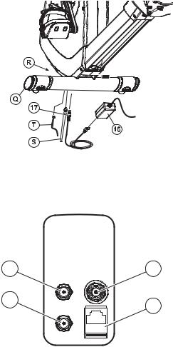
Route the POWER CORD (17) under the FRONT STABILIZER (Q) and install the screw-type connector to the appropriate receptacle of the MEDIA CONNECTOR BOARD (R). Bundle excess POWER CORD and store under the unit.
Connect the BROADCAST SUPPLY CABLE (S) and NETWORK CABLE (T) to the MEDIA CONNECTOR BOARD.
Connect the POWER CORD to the POWER BLOCK.
MEDIA CONNECTOR BOARD RECEPTACLES:
a.12 V POWER FOR ATTACHABLE TV
b.36 V EXTERNAL POWER FOR ENGAGE CONSOLE (15” LCD)
c.BROADCAST SUPPLY INPUT (COAXIAL)
d.FITNESS NETWORK; C-SAFE OR ETHERNET
a |
c |
b |
d |
|

Physical Dimensions:
Length |
65 inches / 165 centimeters |
Width |
27 inches / 68.5 centimeters |
Height |
53 inches / 134.6 centimeters |
Weight |
214 pounds / 97 kilograms |
PRE-OPERATION CHECKLIST
Ensure that all fasteners are tight.
Make sure the Recumbent Lifecycle® Exercise Bike is properly leveled and stable. (Refer to the Operation Manual)
Ensure that the Leveler Jam Nuts are tight. (Refer to the Operation Manual)
Read the entire Operation manual before using the Recumbent Lifecycle® Exercise Bike.
LISTE DES VÉRIFICATIONS À EFFECTUER AVANT LA MISE EN MARCHE
Vérifiez si tous les dispositifs de fixation sont serrés.
Vérifiez si vélo d'exercice vertical est de niveau et stable. (Référez-vous au manuel d'utilisation.)
Vérifiez si les contre-écrous des vérins de mise à niveau sont serrés. (Référez-vous au manuel d'utilisation.)
Lisez le manuel d'utilisation dans son intégralité avant d'utiliser vélo d'exercice vertical.
Before attempting to operate your Recumbent Lifecycle® Exercise Bike, it is imperative that you familiarize yourself with the contents of the Operation Manual. If your Recumbent Lifecycle® Exercise Bike does not respond as described in the Operation Manual, contact the nearest Life Fitness service center as listed in the Operation Manual.
Life Fitness Customer Support Services (800) 351-3737 or (847) 451-0036
Prior to your call, please be sure you have located and noted the MODEL NUMBER & SERIAL NUMBER.
The Model & Serial number information of your Life Fitness Recumbent Lifecycle® Exercise Bike is listed on a label located on the front stabilizer.
©2009 Life Fitness, a division of Brunswick Corporation. All rights reserved. Life Fitness is a trademark of Brunswick Corporation.
M051-00K66-D010 1.09

95R Lifecycle® Liegeergometer
Montageanleitung

Herzlichen Glückwunsch...
und willkommen bei
Die folgende Teileliste und schrittweise Montageanleitung dienen dazu, den Aufbau dieses Lifecycle® Liegeergometers so einfach wie möglich zu machen.
Bitte lesen Sie die nachfolgenden Informationen sorgfältig, bevor Sie einen Standort für das Lifecycle® Liegeergometer wählen und mit der Montage beginnen.
WICHTIGE SICHERHEITSVORKEHRUNGEN
Den Heimtrainer NICHT im Freien, in Schwimmbeckennähe oder in Räumen mit hoher
Luftfeuchtigkeit aufstellen.
Den Heimtrainer NICHT benutzen, wenn er fallengelassen bzw. anderweitig beschädigt wurde oder Teile des Geräts mit Wasser in Berührung gekommen sind. Wenden Sie sich in diesem
Fall unter der im Benutzerhandbuch angegebenen Nummer an den Life Fitness Kundendienst.
Den Heimtrainer mit MINDESTENS 30 in. (76 cm) Abstand zu einem Fernsehgerät aufstellen.
Mehrere Heimtrainer mit MINDESTENS 42 in. (107 cm) Abstand (zwischen den Mittellinien) voneinander aufstellen, um Störungen (Überlagerung) zwischen Herzfrequenzmonitoren zu vermeiden.
Um den Heimtrainer herum AUSREICHEND Freiraum lassen.
Den Inhalt der Lieferung mit der Teileliste vergleichen. Sollten Teile fehlen, wenden Sie sich bitte unter der im Benutzerhandbuch angegebenen Nummer an den Life Fitness-Kundendienst.
Das Verpackungsmaterial (Kartons) für den Fall einer Rücksendung aufbewahren.
Vor Inbetriebnahme dieses Gerätes das Benutzerhandbuch SORGFÄLTIG lesen.
BENÖTIGTES WERKZEUG FÜR DIE MONTAGE...
Magnetischer Kreuzschlitzschraubendreher, 6 mm Inbusschlüssel und Ratsche, Seitenschneider,
17 mm Steckschlüssel und Ratsche
BESCHREIBUNG DER TEILE
1 |
Einzelsäule |
|
|
|
Anz: |
1 |
|
|
2 |
|
|
M10 X 90 mm Schraube |
|
Anz: 3 |
||||||||||||||||||||||||||||||||||||||||||||||||||||||||||||||||||
|
|
|
|
|
|
|
|
|
|
|
|
|
|
|
|
|
|
|
|
|
|
|
|
|
|
|
|
|
|
|
|
|
|
|
|
|
|
|
|
0017-00101-2035 |
|
|
|
|
|
|
|
|
|
|
|
|
|
|
|
|
|
|
|
|
|
|
||||||||||||||||||
|
|
|
|
|
|
|
|
|
|
|
|
|
|
|
|
|
|
|
|
|
|
|
|
|
|
|
|
|
|
|
|
|
|
|
|
|
|
|
|
|
|
|
|
|
|
|
|
|
|
|
|
|
|
|
|
|
|
|
|
|
|
|
|
|
|
|
|
|
|
|
|
|
|
|
|
|
|
|
|
|
3 |
Kreuzschlitzschraube |
|
|
|
Anz: |
1 |
|
|
4 |
|
|
Display-Konsole |
|
Anz: 1 |
||||||||||||||||||||||||||||||||||||||||||||||||||||||||||||||||||
|
0017-00101-1796 |
|
|
|
|
|
|
|
|
|
|
|
|
|
|
|
|
|
|
|
|
|
|
|
|
|
|
|
|
|
|
|
|
|
|
|
|
|
|
|
|
|
|
|
|
|
|
|
|
|
|
|
|
|
|
|
|
|
|
|
|
|
|
|
|
|
|
|
|
|
|
|
||||||||
5 |
Hintere Abdeckung |
|
|
|
Anz: |
1 |
|
|
6 |
|
|
M5 x 14 mm Kreuzschlitzschraube |
|
Anz: 4 |
||||||||||||||||||||||||||||||||||||||||||||||||||||||||||||||||||
|
|
|
|
|
|
|
|
|
|
|
|
|
|
|
|
|
|
|
|
|
|
|
|
|
|
|
|
|
|
|
|
|
|
|
|
|
|
|
|
0017-00101-1940 |
|
|
|
|
|
|
|
|
|
|
|
|
|
|
|
|
|
|
|
|
|
|
||||||||||||||||||
|
|
|
|
|
|
|
|
|
|
|
|
|
|
|
|
|
|
|
|
|
|
|
|
|
|
|
|
|
|
|
|
|
|
|
|
|
|
|
|
|
|
|
|
|
|
|
|
|
|
|
|
|
|
|
|
|
|
|
|
|
|
|
|
|
|
|
|
|
|
|
|
|
|
|
|
|
|
|
|
|
7 |
Handlauf |
|
|
|
Anz: |
1 |
|
|
8 |
|
|
M8 X 20 mm Schraube |
|
Anz: 8 |
||||||||||||||||||||||||||||||||||||||||||||||||||||||||||||||||||
|
|
|
|
|
|
|
|
|
|
|
|
|
|
|
|
|
|
|
|
|
|
|
|
|
|
|
|
|
|
|
|
|
|
|
|
|
|
|
|
0017-00101-1881 |
|
|
|
|
|
|
|
|
|
|
|
|
|
|
|
|
|
|
|
|
|
|
||||||||||||||||||
9 |
M8 Unterlegscheibe |
|
|
|
Anz: |
10 |
|
10 |
|
Ablagenhalter |
|
Anz: 1 |
||||||||||||||||||||||||||||||||||||||||||||||||||||||||||||||||||||
|
0017-00104-0469 |
|
|
|
|
|
|
|
|
|
|
|
|
|
|
|
|
|
|
|
|
|
|
|
|
|
|
|
|
|
|
|
|
|
|
|
|
|
|
|
|
|
|
|
|
|
|
|
|
|
|
|
|
|
|
|
|
|
|
|
|
|
|
|
|
|
|
|
|
|
|
|
||||||||
|
|
|
|
|
|
|
|
|
|
|
|
|
|
|
|
|
|
|
|
|
|
|
|
|
|
|
|
|
|
|
|
|
|
|
|
|
|
|
|
|
|
|
|
|
|
|
|
|
|
|
|
|
|
|
|
|
|
|
|
|
|
|
|
|
|
|
|
|
|
|
|
|
|
|
|
|
|
|
|
|
11 |
M8 X 16 mm Schraube |
|
|
|
Anz: |
2 |
|
|
12 |
|
Sitz |
|
Anz: 1 |
|||||||||||||||||||||||||||||||||||||||||||||||||||||||||||||||||||
|
0017-00101-2030 |
|
|
|
|
|
|
|
|
|
|
|
|
|
|
|
|
|
|
|
|
|
|
|
|
|
|
|
|
|
|
|
|
|
|
|
|
|
|
|
|
|
|
|
|
|
|
|
|
|
|
|
|
|
|
|
|
|
|
|
|
|
|
|
|
|
|
|
|
|
|
|
||||||||
|
|
|
|
|
|
|
|
|
|
|
|
|
|
|
|
|
|
|
|
|
|
|
|
|
|
|
|
|
|
|
|
|
|
|
|
|
|
|
|
|
|
|
|
|
|
|
|
|
|
|
|
|
|
|
|
|
|
|
|
|
|
|
|
|
|
|
|
|
|
|
|
|
|
|
|
|
|
|
|
|
13 |
Ablage |
|
|
|
Anz: |
1 |
|
|
14 |
|
Sitzrücken |
|
Anz: 1 |
|||||||||||||||||||||||||||||||||||||||||||||||||||||||||||||||||||
|
|
|
|
|
|
|
|
|
|
|
|
|
|
|
|
|
|
|
|
|
|
|
|
|
|
|
|
|
|
|
|
|
|
|
|
|
|
|
|
|
|
|
|
|
|
|
|
|
|
|
|
|
|
|
|
|
|
|
|
|
|
|
|
|
|
|
|
|
|
|
|
|
|
|
|
|
|
|
|
|
15 |
M8 X 60 mm Schraube |
|
|
|
Anz: |
4 |
|
|
16 |
|
Stromblock (nur für die Engage Konsole) |
|
Anz.: 1 |
|||||||||||||||||||||||||||||||||||||||||||||||||||||||||||||||||||
|
0017-00101-2018 |
|
|
|
|
|
|
|
|
|
|
|
|
|
|
|
|
|
|
|
|
|
|
|
|
|
|
|
|
|
|
|
|
|
|
|
|
|
|
|
|
|
|
|
|
|
|
|
|
|
|
|
|
|
|
|
|
|
|
|
|
|
|
|
|
|
|
|
|
|
|
|
||||||||
|
|
|
|
|
|
|
|
|
|
|
|
|
|
|
|
|
|
|
|
|
|
|
|
|
|
|
|
|
|
|
|
|
|
|
|
|
|
|
|
|
|
|
|
|
|
|
|
|
|
|
|
|
|
|
|
|
|
|
|
|
|
|
|
|
|
|
|
|
|
|
|
|
|
|
|
|
|
|
|
|
17 |
Netzkabel (nur für die Engage Konsole) |
|
|
|
Anz.: |
1 |
|
|
18 |
|
M5 Unterlegscheibe |
|
Anz: 1 |
|||||||||||||||||||||||||||||||||||||||||||||||||||||||||||||||||||
|
|
|
|
|
|
|
|
|
|
|
|
|
|
|
|
|
|
|
|
|
|
|
|
|
|
|
|
|
|
|
|
|
|
|
|
|
|
|
|
0017-00104-0494 |
|
|
|
|
|
|
|
|
|
|
|
|
|
|
|
|
|
|
|
|
|
|
||||||||||||||||||
19 |
Mutternplatte |
|
|
|
Anz.: |
1 |
|
|
20 |
|
Platte mit zwei Öffnungen |
|
Anz.: 1 |
|||||||||||||||||||||||||||||||||||||||||||||||||||||||||||||||||||
|
|
|
|
|
|
|
|
|
|
|
|
|
|
|
|
|
|
|
|
|
|
|
|
|
|
|
|
|
|
|
|
|
|
|
|
|
|
|
|
|
|
|
|
|
|
|
|
|
|
|
|
|
|
|
|
|
|
|
|
|
|
|
|
|
|
|
|
|
|
|
|
|
|
|
|
|
|
|
|
|
21 |
Platte mit einer Öffnung |
|
|
|
Anz.: |
1 |
|
|
|
|
|
|
|
|
|
|
|
|
|
|
|
|
|
|
|
|
|
|
|
|
|
|
|
|
|
|
|
|
|
|
|
|
|
|
|
|
|
|
|
|
|
|
|
|||||||||||||||||||||||||||
|
|
|
|
|
|
|
|
|
|
|
|
|
|
|
|
|
|
|
|
|
|
|
|
|
|
|
|
|
|
|
|
|
|
|
|
|
|
|
|
|
|
|
|
|
|
|
|
|
|
|
|
|
|
|
|
|
|
|
|
|
|
|
|
|
|
|
|
|
|
|
|
|
|
|
|
|
|
|
|
|
|
|
|
|
|
|
|
|
|
|
|
|
|
|
|
|
|
|
|
|
|
|
|
|
|
|
|
|
|
|
|
|
|
|
|
|
|
|
|
|
|
|
|
|
|
|
|
|
|
|
|
|
|
|
|
|
|
|
|
|
|
|
|
|
|
|
|
|
|
|
|
|
|
|
|
|
|
|
|
|
|
|
|
|
|
|
|
|
|
|
|
|
|
|
|
|
|
|
|
|
|
|
|
|
|
|
|
|
|
|
|
|
|
|
|
|
|
|
|
|
|
|
|
|
|
|
|
|
|
|
|
|
|
|
|
|
|
|
|
|
|
|
|
|
|
|
|
|
|
|
|
|
|
|
|
|
|
|
|
|
|
|
|
|
|
|
|
|
|
|
|
|
|
|
|
|
|
|
|
|
|
|
|
|
|
|
|
|
|
|
|
|
|
|
|
|
|
|
|
|
|
|
|
|
|
|
|
|
|
|
|
|
|
|
|
|
|
|
|
|
|
|
|
|
|
|
|
|
|
|
|
|
|
|
|
|
|
|
|
|
|
|
|
|
|
|
|
|
|
|
|
|
|
|
|
|
|
|
|
|
|
|
|
|
|
|
|
|
|
|
|
|
|
|
|
|
|
|
|
|
|
|
|
|
|
|
|
|
|
|
|
|
|
|
|
|
|
|
|
|
|
|
|
|
|
|
|
|
|
|
|
|
|
|
|
|
|
|
|
|
|
|
|
|
|
|
|
|
|
|
|
|
|
|
|
|
|
|
|
|
|
|
|
|
|
|
|
|
|
|
|
|
|
|
|
|
|
|
|
|
|
|
|
|
|
|
|
|
|
|
|
|
|
|
|
|
|
|
|
|
|
|
|
|
|
|
|
|
|
|
|
|
|
|
|
|
|
|
|
|
|
|
|
|
|
|
|
|
|
|
|
|
|
|
|
|
|
|
|
|
|
|
|
|
|
|
|
|
|
|
|
|
|
|
|
|
|
|
|
|
|
|
|
|
|
|
|
|
|
|
|
|
|
|
|
|
|
|
|
|
|
|
|
|
|
|
|
|
|
|
|
|
|
|
|
|
|
|
|
|
|
|
|
|
|
|
|
|
|
|
|
|
|
|
|
|
|
|
|
|
|
|
|
|
|
|
|
|
|
|
|
|
|
|
|
|
|
|
|
|
|
|
|
|
|
|
|
|
|
|
|
|
|
|
|
|
|
|
|
|
|
|
|
|
|
|
|
|
|
|
|
|
|
|
|
|
|
|
|
|
|
|
|
|
|
|
|
|
|
|
|
|
|
|
|
|
|
|
|
|
|
|
|
|
|
|
|
|
|
|
|
|
|
|
|
|
|
|
|
|
|
|
|
|
|
|
|
|
|
|
|
|
|
|
|
|
|
|
|
|
|
|
|
|
|
|
|
|
|
|
|
|
|
|
|
|
|
|
|
|
|
|
|
|
|
|
|
|
|
|
|
|
|
|
|
|
|
|
|
|
|
|
|
|
|
|
|
|
|
|
|
|
|
|
|
|
|
|
|
|
|
|
|
|
|
|
|
|
|
|
|
|
|
|
|
|
|
|
|
|
|
|
|
|
|
|
|
|
|
|
|
|
|
|
|
|
|
|
|
|
|
|
|
|
|
|
|
|
|
|
|
|
|
|
|
|
|
|
|
|
|
|
|
|
|
|
|
|
|
|
|
|
|
|
|
|
|
|
|
|
|
|
|
|
|
|
|
|
|
|
|
|
|
|
|
|
|
|
|
|
|
|
|
|
|
|
|
|
|
|
|
|
|
|
|
|
|
|
|
|
|
|
|
|
|
|
|
|
|
|
|
|
|
|
|
|
|
|
|
|
|
|
|
|
|
|
|
|
|
|
|
|
|
|
|
|
|
|
|
|
|
|
|
|
|
|
|
|
|
|
|
|
|
|
|
|
|
|
|
|
|
|
|
|
|
|
|
|
|
|
|
|
|
|
|
|
|
|
|
|
|
|
|
|
|
|
|
|
|
|
|

WICHTIG!
DAS VERSANDKIT NICHT ENTSORGEN. DIESES KIT ENTHÄLT ALLE FÜR DIE INSTALLATION
BENÖTIGTEN KOMPONENTEN.
1.Das Gerät in der Nähe des Verwendungsortes positionieren.
2.Den VERSCHLUSSSTECKER FÜR DEN LINKEN TRETKURBELARM (A) ENTFERNEN und zur Seite legen. Die SCHRAUBE DES LINKEN TRETKURBELARMS
(B) ENTFERNEN und den TRETKURBELARM (C) von der Einheit ziehen. Beide Teile aufbewahren.
3. Die sieben SCHRAUBEN (D), mit denen die LINKE VORDERE VERKLEIDUNG (E) BEFESTIGT IST, ENTFERNEN. Die VORDERE VERKLEIDUNG entfernen und beiseite legen.
4. Die EINZELSÄULE (1) auf die VORDERE STANGE (F) SCHIEBEN. Die MUTTERNPLATTE (19), DIE PLATTE MIT ZWEI ÖFFNUNGEN (20) und DIE PLATTE MIT EINER ÖFFNUNG (21) an der Vorderund Rückseite der EINZELSÄULE wie abgebildet positionieren und ausrichten. Die EINZELSÄULE mit drei M10 x 90mm SCHRAUBEN (2) BEFESTIGEN. Die SCHRAUBENauf ein Drehmoment
von 50–55 ft.-lbs (67–74 Nm) anziehen.
HINWEIS: Darauf achten, dass die Kabel nicht eingeklemmt werden, wenn DIE EINZELSÄULE über die VORDERE
STANGE GESCHOBEN WIRD.
Die VORDERE LINKE VERKLEIDUNG (E) wieder mit
den sieben zuvor entfernten SCHRAUBEN (D) ANBRINGEN.
Den TRETKURBELARM (C) erneut mit DER ZUVOR ENTFERNTEN SCHRAUBE FÜR DEN TRETKURBELARM (B) befestigen. Die SCHRAUBEN auf
ein Drehmoment von 30-33 ft.-lbs (67–74 Nm) anziehen. Den Verschlussstecker des LINKEN TRETKURBELARMS (A) WIEDER EINSETZEN.
Die VORDERE ABLAGE (G) nach unten auf die VORDERE VERKLEIDUNG
(E) SCHIEBEN. Die vordere ABLAGE mit einer SCHRAUBE (3) und einer M5 UNTERLEGSCHEIBE (18) BEFESTIGEN. Die SCHRAUBEN fest anziehen. Die SCHRAUBEN nicht zu fest anziehen.
5.Den Kabelbinder, mit der die Kabel an der
KONSOLENHALTERUNG(H) befestigt sind, durchschneiden.
Die DISPLAY-KONSOLE (4) neben der KONSOLENHALTERUNG
(H) POSITIONIEREN. Das HAUPTKONSOLENKABEL (J), DAS NETZWERKKABEL (K) und das ERDUNGSKABEL (L), die jeweils die EINZELSÄULE (1) mit den entsprechenden
Anschlüssen auf der Rückseite der DISPLAY-KONSOLE
VERBINDEN, ANSCHLIEßEN.
HINWEIS: Wenn C-SAFE VERWENDET WIRD, das NETZWERKKABEL an den SCHWARZEN ANSCHLUSS
ANSCHLIEßEN. Wenn ETHERNET VERWENDET WIRD, das NETZWERKKABEL an den SILBERNEN ANSCHLUSS ANSCHLIEßEN.
Für Einheiten mit Engage Konsole (15” LCD)
Das KOAXIALKABEL (M) ANSCHLIEßEN, die von der EINZELSÄULE (1) auf die Rückseite der DISPLAY-KONSOLE FÜHREN.
HINWEIS: Sicherstellen, DASS DIE STECKVERBINDER vollständig ineinander eingesteckt sind.
Nicht verwendete Kabel zusammenfassen und mit Kabelbindern an der Seite der Mittelsäule an der KONSOLENHALTERUNG BEFESTIGEN. Die Montageöffnungen nicht blockieren.
Die DISPLAY-KONSOLE auf die KONSOLENHALTERUNG AUFSETZEN. Die HINTERE ABDECKUNG (5) auf der Rückseite der DISPLAY-KONSOLE positionieren und mit vier SCHRAUBEN(6) sichern. Die SCHRAUBEN fest anziehen. Die SCHRAUBEN nicht zu fest anziehen.

6.Die HALTEGRIFFE (7) wie gezeigt positionieren. Jeden HALTEGRIFF mit je
zwei M8 x 20mmSCHRAUBEN (8) und je zwei M8 UNTERLEGSCHEIBEN
(9) am SITZRAHMEN (N) befestigen.
HINWEIS: Sicherstellen, dass die ZUNGEN der HALTEGRIFFE wie gezeigt in die Schlitze unter dem SITZRAHMEN eingeschoben werden, bevor die Haltegriffe
befestigt werden.
DIE Herzfrequenzkabel (O) anschließen, die von den HALTEGRIFFEN zum HAUPTKABEL (P) im SITZRAHMEN FÜHREN.
HINWEIS: Sicherstellen, DASS DIE STECKVERBINDER vollständig ineinander eingesteckt sind.
7. Die ABLAGENHALTERUNG (10) mit zwei M8 x 16 mm SCHRAUBEN (11) und zwei M8 UNTERLEGSCHEIBEN (9) AM Sitzrahmen (N) befestigen. Die SCHRAUBEN fest anziehen. Die SCHRAUBEN NICHT ZU FEST ANZIEHEN.
Den SITZ (12) mit vier M8 x 20 mm SCHRAUBEN (8) und zwei M8 UNTERLEGSCHEIBEN (9) AM Sitzrahmen (N) sichern. Die SCHRAUBEN fest anziehen. Die SCHRAUBEN nicht zu fest anziehen.
Die ABLAGE (13) wie gezeigt auf dem ABLAGENHALTER positionieren. Die ABLAGE fest nach unten drücken, um sie zu befestigen.
8.Den SITZRÜCKEN (14) MIT VIER Schrauben (15) am SITZRAHMEN (N) befestigen. Die SCHRAUBEN fest anziehen. Die SCHRAUBEN nicht zu
fest anziehen.
9.Für Einheiten mit Engage Konsole
Das Gerät am dauerhaften Aufstellungsort positionieren.
Den Schutzfilm von einem der HAFTSTREIFEN abziehen. Den Haftstreifen an der Unterseite des STROMBLOCKS (16) ANBRINGEN. Den verbleibenden HAFTSTREIFEN am befestigten HAFTSTREIFEN ANBRINGEN. Den verbleibenden Schutzfilm vom HAFTSTREIFEN abziehen und den STROMBLOCK wie gezeigt auf der Unterseite des MITTELRAHMENS anbringen.
Das STROMKABEL (17) unter dem VORDEREN STABILISATOR (Q) entlangführen und den Schraubanschluss am entsprechenden Anschluss an der MEDIENANSCHLUSSKONSOLE (R) festschrauben. Das restliche NETZKABEL bündeln und unter der Einheit verstauen.
Das ÜbertragungsKABEL (S) und NETZWERKKABEL (T) an der MEDIENANSCHLUSSKONSOLE anschließen.
Das NETZKABELan den STROMBLOCK anschließen.
ANSCHLÜSSE AN DER MEDIENANSCHLUSSKONSOLE:
a.12 V STROMVERSORGUNG FÜR TV-ANSCHLUSS
b.36 V EXTERNER STROMANSCHLUSS FÜR ENGAGE KONSOLE (15” LCD)
c.ÜBERTRAGUNGSEINGANG (KOAXIAL)
d.FITNESS-NETZWERK; C-SAFE ODER ETHERNET
a |
c |
b |
d |
|

Geräteabmessungen:
Länge |
65 inches/165 cm |
Breite |
27 inches/68,5 cm |
Höhe |
53 inches/134,6 cm |
Gewicht |
97 kg |
CHECKLISTE VOR INBETRIEBNAHME
Sicherstellen, dass alle Befestigungselemente fest angezogen sind.
Sicherstellen, dass das Lifecycle® Liegeergometer eben und stabil aufgestellt ist. (Siehe Benutzerhandbuch.)
Sicherstellen, dass die Kontermuttern der Einstellfüße fest angezogen sind. (Siehe Benutzerhandbuch.)
Das Benutzerhandbuch vor Verwendung des Lifecycle® Liegeergometers lesen.
Vor Verwendung des Lifecycle® Liegeergometers das Benutzerhandbuch lesen. Wenn Ihr Lifecycle® Liegeergometer nicht wie in der im Benutzerhandbuch beschriebenen Weise funktioniert, wenden Sie sich bitte an das im Benutzerhandbuch angegebene Life Fitness Service Center in Ihrer Nähe.
Life Fitness Kundendienst
(800) 351-3737 (in den USA) oder +1 (847) 451-0036
Beim Anruf immer die MODELLUND SERIENNUMMER bereithalten.
Die Modellund Seriennummern des Lifecycle® Liegeergometers sind auf einem Schild an der hinteren Stabilisatorstange zu finden.
© 2009 Life Fitness, eine Firma der Brunswick Corporation. Alle Rechte vorbehalten. Life Fitness ist ein Warenzeichen der Brunswick Corporation.
M051-00K66-D010 1.09

95R Lifecycle® ligfietshometrainer
Aanwijzingen voor montage

Gefeliciteerd...
en welkom in de wereld van
De bijgevoegde onderdelenlijst en de stapsgewijze montageprocedure zijn samengesteld om de montage van de Lifecycle® ligfiets-hometrainer zo snel en eenvoudig mogelijk te laten verlopen.
Wilt u speciale aandacht aan de volgende belangrijke punten schenken voordat u de locatie kiest en de Lifecycle® ligfietshometrainer gaat monteren.
BELANGRIJKE VEILIGHEIDSAANWIJZINGEN!
Gebruik de hometrainer NIET buiten, naast zwembaden of in ruimten met een hoge vochtigheidsgraad.
Gebruik de hometrainer NIET als hij gevallen of beschadigd is, of als er water overheen gekomen is. Neem in zulke gevallen contact op met de klantendienst van Life Fitness, waarvan u het nummer in de gebruikershandleiding kunt vinden.
Plaats de hometrainer NIET op minder dan 76 cm (30 inch) van een televisietoestel.
Plaats extra hometrainers NIET op een onderlinge afstand van minder dan 107 cm - van middelpunt tot middelpunt – (van elkaar) om wederzijdse storing van de hartslagmonitors te voorkomen.
Houd de ruimte rondom de hometrainer VRIJ van obstakels, met inbegrip van muren en meubilair.
CONTROLEER de inhoud van de geleverde doos aan de hand van de bijgevoegde onderdelenlijst voordat u de dozen en het verpakkingsmateriaal opzij legt. Neem als er onderdelen ontbreken contact op met de klantendienst van Life Fitness waarvan u het telefoonnummer in de gebruikershandleiding vindt. Bewaar de verzenddozen ingeval het product moet worden teruggestuurd.
NEEM de gebruikershandleiding helemaal door voordat u het toestel voor het eerst in gebruik neemt. Dit is essentieel voor een goed resultaat.

BENODIGD GEREEDSCHAP...
Kruiskopschroevendraaier met magnetisch bit nr. 2; 6 mm inbusmoersleutel met ratel, gehoekte kniptang; 17 mm steeksleutel met ratel
BESCHRIJVING ONDERDELEN
1 |
Kolom |
|
Aantal: 1 |
2 |
|
|
M10 X 90MM schroef |
|
|
|
Aantal: |
3 |
||||||||||||||||||||||||||||||||||||||||||||||||||||||||||||||||||||
|
|
|
|
|
|
|
|
|
|
|
|
|
|
|
|
|
|
|
|
|
|
|
|
|
|
|
|
|
|
|
|
|
|
|
|
|
|
|
|
0017-00101-2035 |
|
|
|
|
|
|
|
|
|
|
|
|
|
|
|
|
|
|
|
|
|
|
||||||||||||||||||
|
|
|
|
|
|
|
|
|
|
|
|
|
|
|
|
|
|
|
|
|
|
|
|
|
|
|
|
|
|
|
|
|
|
|
|
|
|
|
|
|
|
|
|
|
|
|
|
|
|
|
|
|
|
|
|
|
|
|
|
|
|
|
|
|
|
|
|
|
|
|
|
|
|
|
|
|
|
|
|
|
3 |
Kruiskopschroef |
|
Aantal: 1 |
4 |
|
|
Bedieningspaneel |
|
|
|
Aantal: |
1 |
||||||||||||||||||||||||||||||||||||||||||||||||||||||||||||||||||||
|
0017-00101-1796 |
|
|
|
|
|
|
|
|
|
|
|
|
|
|
|
|
|
|
|
|
|
|
|
|
|
|
|
|
|
|
|
|
|
|
|
|
|
|
|
|
|
|
|
|
|
|
|
|
|
|
|
|
|
|
|
|
|
|
|
|
|
|
|
|
|
|
|
|
|
|
|
||||||||
5 |
Achterkap |
|
Aantal: 1 |
6 |
|
|
M5 x 14mm kruiskopschroef |
|
|
|
Aantal: |
4 |
||||||||||||||||||||||||||||||||||||||||||||||||||||||||||||||||||||
|
|
|
|
|
|
|
|
|
|
|
|
|
|
|
|
|
|
|
|
|
|
|
|
|
|
|
|
|
|
|
|
|
|
|
|
|
|
|
|
0017-00101-1940 |
|
|
|
|
|
|
|
|
|
|
|
|
|
|
|
|
|
|
|
|
|
|
||||||||||||||||||
7 |
Handgreep |
|
Aantal: 1 |
8 |
|
|
M8 X 20MM schroef |
|
|
|
Aantal: |
8 |
||||||||||||||||||||||||||||||||||||||||||||||||||||||||||||||||||||
|
|
|
|
|
|
|
|
|
|
|
|
|
|
|
|
|
|
|
|
|
|
|
|
|
|
|
|
|
|
|
|
|
|
|
|
|
|
|
|
0017-00101-1881 |
|
|
|
|
|
|
|
|
|
|
|
|
|
|
|
|
|
|
|
|
|
|
||||||||||||||||||
9 |
M8 ring |
|
Aantal: 10 |
10 |
|
Bevestiging accessoirehouder |
|
|
|
Aantal: |
1 |
|||||||||||||||||||||||||||||||||||||||||||||||||||||||||||||||||||||
|
0017-00104-0469 |
|
|
|
|
|
|
|
|
|
|
|
|
|
|
|
|
|
|
|
|
|
|
|
|
|
|
|
|
|
|
|
|
|
|
|
|
|
|
|
|
|
|
|
|
|
|
|
|
|
|
|
|
|
|
|
|
|
|
|
|
|
|
|
|
|
|
|
|
|
|
|
||||||||
11 |
M8 X 16MM schroef |
|
Aantal: 2 |
12 |
|
Zitting |
|
|
|
Aantal: |
1 |
|||||||||||||||||||||||||||||||||||||||||||||||||||||||||||||||||||||
|
0017-00101-2030 |
|
|
|
|
|
|
|
|
|
|
|
|
|
|
|
|
|
|
|
|
|
|
|
|
|
|
|
|
|
|
|
|
|
|
|
|
|
|
|
|
|
|
|
|
|
|
|
|
|
|
|
|
|
|
|
|
|
|
|
|
|
|
|
|
|
|
|
|
|
|
|
||||||||
13 |
Accessoirehouder |
|
Aantal: 1 |
14 |
|
Rugleuning |
|
|
|
Aantal: |
1 |
|||||||||||||||||||||||||||||||||||||||||||||||||||||||||||||||||||||
|
|
|
|
|
|
|
|
|
|
|
|
|
|
|
|
|
|
|
|
|
|
|
|
|
|
|
|
|
|
|
|
|
|
|
|
|
|
|
|
|
|
|
|
|
|
|
|
|
|
|
|
|
|
|
|
|
|
|
|
|
|
|
|
|
|
|
|
|
|
|
|
|
|
|
|
|
|
|
|
|
15 |
M8 X 60MM schroef |
|
Aantal: 4 |
16 |
|
Voedingsblok |
|
|
|
Aantal: |
1 |
|||||||||||||||||||||||||||||||||||||||||||||||||||||||||||||||||||||
|
0017-00101-2018 |
|
|
|
|
|
|
|
|
|
|
|
|
|
|
|
|
|
|
|
|
|
|
|
|
|
|
|
|
|
|
(alleen voor Engage-bedieningspaneel) |
|
|
|
|
|
|
|
|
|
|||||||||||||||||||||||||||||||||||||||
17 |
Voedingskabel |
|
Aantal: 1 |
18 |
|
M5 Ring |
|
|
|
Aantal: |
1 |
|||||||||||||||||||||||||||||||||||||||||||||||||||||||||||||||||||||
|
(alleen voor Engage-bedieningspaneel) |
|
|
|
|
|
|
|
|
|
|
|
|
|
|
0017-00104-0494 |
|
|
|
|
|
|
|
|
|
|
|
|
|
|
|
|
|
|
|
|
|
|
||||||||||||||||||||||||||||||||||||||||||
19 |
Moerplaat |
|
Aantal: 1 |
20 |
|
Plaat met twee gaten |
|
|
|
Aantal: |
1 |
|||||||||||||||||||||||||||||||||||||||||||||||||||||||||||||||||||||
|
|
|
|
|
|
|
|
|
|
|
|
|
|
|
|
|
|
|
|
|
|
|
|
|
|
|
|
|
|
|
|
|
|
|
|
|
|
|
|
|
|
|
|
|
|
|
|
|
|
|
|
|
|
|
|
|
|
|
|
|
|
|
|
|
|
|
|
|
|
|
|
|
|
|
|
|
|
|
|
|
21 |
Plaat met één gat |
|
Aantal: 1 |
|
|
|
|
|
|
|
|
|
|
|
|
|
|
|
|
|
|
|
|
|
|
|
|
|
|
|
|
|
|
|
|
|
|
|
|
|
|
|
|
|
|
|
|
|
||||||||||||||||||||||||||||||||
|
|
|
|
|
|
|
|
|
|
|
|
|
|
|
|
|
|
|
|
|
|
|
|
|
|
|
|
|
|
|
|
|
|
|
|
|
|
|
|
|
|
|
|
|
|
|
|
|
|
|
|
|
|
|
|
|
|
|
|
|
|
|
|
|
|
|
|
|
|
|
|
|
|
|
|
|
|
|
|
|
|
|
|
|
|
|
|
|
|
|
|
|
|
|
|
|
|
|
|
|
|
|
|
|
|
|
|
|
|
|
|
|
|
|
|
|
|
|
|
|
|
|
|
|
|
|
|
|
|
|
|
|
|
|
|
|
|
|
|
|
|
|
|
|
|
|
|
|
|
|
|
|
|
|
|
|
|
|
|
|
|
|
|
|
|
|
|
|
|
|
|
|
|
|
|
|
|
|
|
|
|
|
|
|
|
|
|
|
|
|
|
|
|
|
|
|
|
|
|
|
|
|
|
|
|
|
|
|
|
|
|
|
|
|
|
|
|
|
|
|
|
|
|
|
|
|
|
|
|
|
|
|
|
|
|
|
|
|
|
|
|
|
|
|
|
|
|
|
|
|
|
|
|
|
|
|
|
|
|
|
|
|
|
|
|
|
|
|
|
|
|
|
|
|
|
|
|
|
|
|
|
|
|
|
|
|
|
|
|
|
|
|
|
|
|
|
|
|
|
|
|
|
|
|
|
|
|
|
|
|
|
|
|
|
|
|
|
|
|
|
|
|
|
|
|
|
|
|
|
|
|
|
|
|
|
|
|
|
|
|
|
|
|
|
|
|
|
|
|
|
|
|
|
|
|
|
|
|
|
|
|
|
|
|
|
|
|
|
|
|
|
|
|
|
|
|
|
|
|
|
|
|
|
|
|
|
|
|
|
|
|
|
|
|
|
|
|
|
|
|
|
|
|
|
|
|
|
|
|
|
|
|
|
|
|
|
|
|
|
|
|
|
|
|
|
|
|
|
|
|
|
|
|
|
|
|
|
|
|
|
|
|
|
|
|
|
|
|
|
|
|
|
|
|
|
|
|
|
|
|
|
|
|
|
|
|
|
|
|
|
|
|
|
|
|
|
|
|
|
|
|
|
|
|
|
|
|
|
|
|
|
|
|
|
|
|
|
|
|
|
|
|
|
|
|
|
|
|
|
|
|
|
|
|
|
|
|
|
|
|
|
|
|
|
|
|
|
|
|
|
|
|
|
|
|
|
|
|
|
|
|
|
|
|
|
|
|
|
|
|
|
|
|
|
|
|
|
|
|
|
|
|
|
|
|
|
|
|
|
|
|
|
|
|
|
|
|
|
|
|
|
|
|
|
|
|
|
|
|
|
|
|
|
|
|
|
|
|
|
|
|
|
|
|
|
|
|
|
|
|
|
|
|
|
|
|
|
|
|
|
|
|
|
|
|
|
|
|
|
|
|
|
|
|
|
|
|
|
|
|
|
|
|
|
|
|
|
|
|
|
|
|
|
|
|
|
|
|
|
|
|
|
|
|
|
|
|
|
|
|
|
|
|
|
|
|
|
|
|
|
|
|
|
|
|
|
|
|
|
|
|
|
|
|
|
|
|
|
|
|
|
|
|
|
|
|
|
|
|
|
|
|
|
|
|
|
|
|
|
|
|
|
|
|
|
|
|
|
|
|
|
|
|
|
|
|
|
|
|
|
|
|
|
|
|
|
|
|
|
|
|
|
|
|
|
|
|
|
|
|
|
|
|
|
|
|
|
|
|
|
|
|
|
|
|
|
|
|
|
|
|
|
|
|
|
|
|
|
|
|
|
|
|
|
|
|
|
|
|
|
|
|
|
|
|
|
|
|
|
|
|
|
|
|
|
|
|
|
|
|
|
|
|
|
|
|
|
|
|
|
|
|
|
|
|
|
|
|
|
|
|
|
|
|
|
|
|
|
|
|
|
|
|
|
|
|
|
|
|
|
|
|
|
|
|
|
|
|
|
|
|
|
|
|
|
|
|
|
|
|
|
|
|
|
|
|
|
|
|
|
|
|
|
|
|
|
|
|
|
|
|
|
|
|
|
|
|
|
|
|
|
|
|
|
|
|
|
|
|
|
|
|
|
|
|
|
|
|
|
|
|
|
|
|
|
|
|
|
|
|
|
|
|
|
|
|
|
|
|
|
|
|
|
|
|
|
|
|
|
|
|
|
|
|
|
|
|
|
|
|
|
BELANGRIJK!
GOOI DE VERPAKKINGSSET NIET WEG. ALLE ONDERDELEN DIE NODIG ZIJN OM DE
INSTALLATIE TE VOLTOOIEN BEVINDEN ZICH IN DE VERPAKKINGSSET.
1.Zet de hometrainer in de buurt van waar u hem wilt gebruiken.
2.Verwijder de LINKER KRUKARMPLUG (A) en leg deze opzij. Verwijder de LINKER KRUKARMSCHROEF (B) en schuif de KRUKARM (C) van de eenheid. Leg beide onderdelen opzij.
3.Verwijder de zeven SCHROEVEN (D) voor bevestiging van de LINKER VOORKAP
(E). Verwijder de VOORKAP en leg deze opzij.
4. Schuif de KOLOM (1) over de VOORSTE BUIS (F) heen. Breng de MOERPLAAT (19), de PLAAT MET TWEE GATEN (20) en de PLAAT MET ÉÉN GAT (21) aan de voorkant en achterkant van de KOLOM zoals afgebeeld aan en lijn ze uit. Bevestig de KOLOM met drie M10 x 90mm SCHROEVEN (2). Draai de SCHROEVEN aan tot 50-55 ft.-lbs.
OPMERKING: Pas op dat u geen draden afknelt terwijl u de KOLOM over de VOORSTE BUIS SCHUIFT.
Breng de LINKER VOORKAP (E) weer aan. Gebruik daarvoor de zeven eerder verwijderde SCHROEVEN (D).
Breng de KRUKARM (C) weer aan. Gebruik daarbij de LINKER KRUKARMSCHROEF (B) die eerder was verwijderd. Draai de SCHROEVENaan tot 30-33 ft.-lbs. Plaats de LINKER KRUKARMPLUG (A) TERUG.
Schuif de VOORSTE ACCESSOIREHOUDER (G) omlaag naar de VOORKAPPEN (E). Bevestig de VOORSTE
ACCESSOIREHOUDER met een KRUISKOPSCHROEF (3) en een M5 RING (18). Draai de SCHROEVEN goed vast. Draai de SCHROEVEN niet te vast aan.
5.Knip de kabelbinder door waarmee de kabels op de
BEDIENINGSPANEELSTEUN (H) zijn bevestigd.
Plaats het BEDIENINGSPANEEL (4) bij de BEDIENINGSPANEELSTEUN
(H). Sluit de HOOFDBEDIENINGSPANEELKABEL (J), DE NETWERKKABEL (K) en de MASSAKABEL (L) vanuit de KOLOM (1) aan op de juiste plaats op de achterkant van het BEDIENINGSPANEEL.
OPMERKING: Als u C-SAFE gebruikt, sluit u de NETWERKKABEL aan op het ZWARTE CONTACT. Als u ETHERNET gebruikt, sluit u de NETWERKKABEL aan op het ZILVERKLEURIGE CONTACT.
Voor hometrainers met Engage-bedieningspaneel (15” LCD)
Sluit de COAXKABEL (M) vanuit de KOLOM (1) aan op de achterkant van het BEDIENINGSPANEEL.
OPMERKING: Zorg dat alle CONNECTORS goed zijn aangesloten.
Voeg ongebruikte kabels samen en bevestig ze met een kabelbinder op de zijkant van de middelste staander van de BEDIENINGSPANEELSTEUN. Blokkeer hierbij geen montageopeningen.
Plaats het BEDIENINGSPANEEL op de BEDIENINGSPANEELSTEUN. Plaats de ACHTERKAP (5) op de achterkant van het BEDIENINGSPANEEL en bevestig hem met de vier SCHROEVEN (6). Draai de SCHROEVEN goed aan. Draai de SCHROEVEN niet te vast aan.
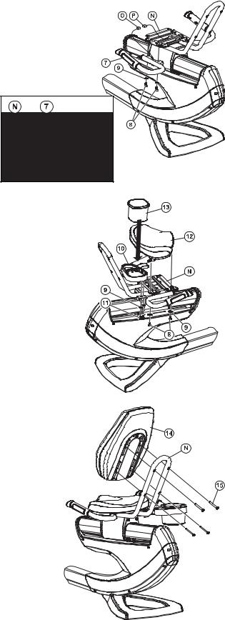
6.Plaats de HANDGREPEN (7) zoals afgebeeld. Bevestig elke HANDGREEP op het ZADELFRAME (N) met twee M8 x 20mm SCHROEVEN (8) en twee M8 RINGEN (9) elk.
OPMERKING: Controleer of de LIPPEN van de HANDGREPEN in de gleuven op de onderkant van het ZADELFRAME zijn gestoken, zoals afgebeeld, voordat u ze vastzet.
SLUIT DE hartfrequentiekabels (O) vanuit de HANDGREPEN aan op de MIDDELSTE DRAAD (P) in het ZADELFRAME.
OPMERKING: Zorg dat alle CONNECTORS goed zijn aangesloten.
7.Monteer de BEVESTIGING VAN DE ACCESSOIREHOUDER (10) op het ZADELFRAME (N) met de twee M8 x 16mm SCHROEVEN (11) en twee M8 RINGEN (9). Draai de SCHROEVEN goed vast. Draai de SCHROEVEN NIET TE VAST AAN.
Bevestig het ZADEL (12) op het ZADELFRAME (N) met vier M8 x 20mm SCHROEVEN (8) en twee M8 RINGEN (9). Draai de SCHROEVEN goed vast. Draai de SCHROEVEN niet te vast aan.
Plaats de ACCESSOIREHOUDER (13) in de BEVESTIGING VOOR DE ACCESSOIREHOUDER zoals afgebeeld. Druk de ACCESSOIREHOUDER omlaag op zijn plaats.
8.Bevestig de RUGLEUNING (14) op het ZADELFRAME (N) met vier SCHROEVEN (15). Draai de SCHROEVEN goed vast. Draai de SCHROEVEN niet te vast aan.

9.Voor hometrainers met Engage-bedieningspaneel
Zet de hometrainer op zijn uiteindelijke gebruikslocatie.
Verwijder het beschermmateriaal van een van de meegeleverde BEVESTIGINGSSTRIPS. Maak de bevestigingsstrip vast op de onderkant van het VOEDINGSBLOK (16). Verbind de andere BEVESTIGINGSSTRIP met de reeds geïnstalleerde BEVESTIGINGSSTRIP. Verwijder het resterende beschermmateriaal van de BEVESTIGINGSSTRIP en bevestig het VOEDINGSBLOK op de onderkant van het MIDDELSTE FRAME, zoals afgebeeld.
Leid de VOEDINGSKABEL (17) onder de VOORSTE STABILISATOR
(Q) door en installeer de schroefconnector op het toepasselijke contact op de MEDIAVERBINDINGSPLAAT (R). Bind overtollige VOEDINGSKABEL samen en berg dit onder het apparaat op.
Sluit de ZENDERKABEL (S) en de NETWERKKABEL (T) aan op de MEDIAVERBINDINGSPLAAT.
Sluit de VOEDINGSKABEL aan op het VOEDINGSBLOK.
AANSLUITPUNTEN MEDIAVERBINDINGSPLAAT:
a.12 V-VOEDING VOOR AANSLUITBARE TV
b.36 V EXTERNE VOEDING VOOR ENGAGE BEDIENINGSPANEEL (15” LCD)
c.INGANG ZENDERSIGNAAL (COAX)
d.FITNESS-NETWERK; C-SAFE OF ETHERNET
a |
c |
b |
d |
|

Afmetingen:
Lengte |
65 inch (165 centimeter) |
Breedte |
27 inch (68,5 centimeter) |
Hoogte |
53 inch (134,6 centimeter) |
Gewicht |
214 pounds / 97 kilo |
CONTROLELIJST VOOR INGEBRUIKNAME
Controleer of alle bevestigingen stevig zijn aangedraaid.
Controleer of de Lifecycle® ligfietshometrainer waterpas staat en stabiel is. (Raadpleeg de gebruikershandleiding.)
Controleer of de contramoeren van de stabilisatiepoten stevig vastzitten. (Raadpleeg de gebruikershandleiding.)
Neem de gebruikershandleiding volledig door voordat u de Lifecycle® ligfietshometrainer gaat gebruiken.
Voordat u met de Lifecycle® ligfietshometrainer gaat werken, is het van essentieel belang dat u de gebruikershandleiding grondig doorneemt. Indien uw Lifecycle® ligfietshometrainer niet reageert zoals beschreven in de gebruikershandleiding, neem dan contact op met het dichtstbijzijnde servicecentrum van Life Fitness, waarvan de lijst is opgenomen in de gebruikershandleiding.
De klantendienst van Life Fitness
Telefoon (800) 351-3737 of (847) 451-0036
Zorg voordat u belt dat u het MODELNUMMER en SERIENUMMER bij de hand hebt.
Het modelen serienummer van uw Life Fitness Lifecycle® ligfietshometrainer vindt u op een sticker op de voorste stabilisatiestang.
© 2009 Life Fitness, een onderdeel van Brunswick Corporation. Alle rechten voorbehouden. Life Fitness is een handelsmerk van Brunswick Corporation.
M051-00K66-D010 1.09

Cyclette reclinata Lifecycle® 95R
Istruzioni per il montaggio

Congratulazioni...
e benvenuti nel mondo di
Il seguente elenco di identificazione dei componenti e le procedure dettagliate di montaggio sono stati redatti per rendere più facile e veloce possibile l’installazione della cyclette reclinata Lifecycle®.
Prima di scegliere l’ubicazione della cyclette reclinata Lifecycle® e di iniziare il montaggio, leggere le seguenti importanti avvertenze.
IMPORTANTI ISTRUZIONI DI SICUREZZA
NON collocare la cyclette all’aperto, in prossimità di piscine o in aree molto umide.
NON utilizzare la cyclette se ha subito urti, se è danneggiata o se è stata immersa in acqua anche solo parzialmente. In tali situazioni contattare il centro assistenza clienti Life Fitness telefonando al numero indicato nel manuale di funzionamento del prodotto.
NON collocare la cyclette a meno di 30 pollici (76 cm) da qualsiasi apparecchio televisivo.
NON posizionare altre cyclette a una distanza inferiore a 42 pollici (107 cm) dal punto centrale di una cyclette all’altro per evitare eventuali interferenze (cross talk) tra i cardiofrequenzimetri.
MANTENERE l’area circostante la cyclette sgombra di ostacoli, compresi mobili e pareti.
VERIFICARE che il contenuto delle scatole di imballaggio corrisponda all’elenco dei componenti prima di disfarsi del materiale di spedizione. Se qualche componente risulta mancante, contattare il centro assistenza clienti Life Fitness al numero indicato nel manuale di funzionamento. Conservare le scatole di imballaggio in caso di restituzione del prodotto.
LEGGERE l’intero manuale di funzionamento prima di utilizzare questo prodotto.

ATTREZZI NECESSARI PER IL MONTAGGIO
Cacciavite a stella magnetico n. 2, chiave a brugola esagonale da 6 mm e cricchetto, taglierine, chiave a bussola da 17 mm e cricchetto
DESCRIZIONE DEI COMPONENTI
1 |
Gruppo monocolonna |
|
|
|
|
|
|
|
|
|
|
|
Qtà: |
1 |
|
|
2 |
|
|
Vite M10 x 90 mm |
|
|
|
|
|
|
|
|
Qtà: |
3 |
||||||||||||||||||||||||||||||||||||||||||||||||||
|
|
|
|
|
|
|
|
|
|
|
|
|
|
|
|
|
|
|
|
|
|
|
|
|
|
|
|
|
|
|
|
|
|
|
|
|
|
|
|
0017-00101-2035 |
|
|
|
|
|
|
|
|
|
|
|
|
|
|
|
|
|
|
|
|
|
|
||||||||||||||||||
|
|
|
|
|
|
|
|
|
|
|
|
|
|
|
|
|
|
|
|
|
|
|
|
|
|
|
|
|
|
|
|
|
|
|
|
|
|
|
|
|
|
|
|
|
|
|
|
|
|
|
|
|
|
|
|
|
|
|
|
|
|
|
|
|
|
|
|
|
|
|
|
|
|
|
|
|
|
|
|
|
3 |
Vite a croce |
|
|
|
|
|
|
|
|
|
|
|
Qtà: |
1 |
|
|
4 |
|
|
Console |
|
|
|
|
|
|
|
|
Qtà: |
1 |
||||||||||||||||||||||||||||||||||||||||||||||||||
|
0017-00101-1796 |
|
|
|
|
|
|
|
|
|
|
|
|
|
|
|
|
|
|
|
|
|
|
|
|
|
|
|
|
|
|
|
|
|
|
|
|
|
|
|
|
|
|
|
|
|
|
|
|
|
|
|
|
|
|
|
|
|
|
|
|
|
|
|
|
|
|
|
|
|
|
|
||||||||
|
|
|
|
|
|
|
|
|
|
|
|
|
|
|
|
|
|
|
|
|
|
|
|
|
|
|
|
|
|
|
|
|
|
|
|
|
|
|
|
|
|
|
|
|
|
|
|
|
|
|
|
|
|
|
|
|
|
|
|
|
|
|
|
|
|
|
|
|
|
|
|
|
|
|
|
|
|
|
|
|
5 |
Copertura posteriore |
|
|
|
|
|
|
|
|
|
|
|
Qtà: |
1 |
|
|
6 |
|
|
Vite a croce M5 x 14 mm |
|
|
|
|
|
|
|
|
Qtà: |
4 |
||||||||||||||||||||||||||||||||||||||||||||||||||
|
|
|
|
|
|
|
|
|
|
|
|
|
|
|
|
|
|
|
|
|
|
|
|
|
|
|
|
|
|
|
|
|
|
|
|
|
|
|
|
0017-00101-1940 |
|
|
|
|
|
|
|
|
|
|
|
|
|
|
|
|
|
|
|
|
|
|
||||||||||||||||||
|
|
|
|
|
|
|
|
|
|
|
|
|
|
|
|
|
|
|
|
|
|
|
|
|
|
|
|
|
|
|
|
|
|
|
|
|
|
|
|
|
|
|
|
|
|
|
|
|
|
|
|
|
|
|
|
|
|
|
|
|
|
|
|
|
|
|
|
|
|
|
|
|
|
|
|
|
|
|
|
|
7 |
Manubrio |
|
|
|
|
|
|
|
|
|
|
|
Qtà: |
1 |
|
|
8 |
|
|
Vite M8 x 20 mm |
|
|
|
|
|
|
|
|
Qtà: |
8 |
||||||||||||||||||||||||||||||||||||||||||||||||||
|
|
|
|
|
|
|
|
|
|
|
|
|
|
|
|
|
|
|
|
|
|
|
|
|
|
|
|
|
|
|
|
|
|
|
|
|
|
|
|
0017-00101-1881 |
|
|
|
|
|
|
|
|
|
|
|
|
|
|
|
|
|
|
|
|
|
|
||||||||||||||||||
|
|
|
|
|
|
|
|
|
|
|
|
|
|
|
|
|
|
|
|
|
|
|
|
|
|
|
|
|
|
|
|
|
|
|
|
|
|
|
|
|
|
|
|
|
|
|
|
|
|
|
|
|
|
|
|
|
|
|
|
|
|
|
|
|
|
|
|
|
|
|
|
|
|
|
|
|
|
|
|
|
9 |
Rondella M8 |
|
|
|
|
|
|
|
|
|
|
|
Qtà: |
10 |
|
10 |
|
Supporto del porta accessori |
|
|
|
|
|
|
|
|
Qtà: |
1 |
||||||||||||||||||||||||||||||||||||||||||||||||||||
|
0017-00104-0469 |
|
|
|
|
|
|
|
|
|
|
|
|
|
|
|
|
|
|
|
|
|
|
|
|
|
|
|
|
|
|
|
|
|
|
|
|
|
|
|
|
|
|
|
|
|
|
|
|
|
|
|
|
|
|
|
|
|
|
|
|
|
|
|
|
|
|
|
|
|
|
|
||||||||
11 |
Vite M8 x 16 mm |
|
|
|
|
|
|
|
|
|
|
|
Qtà: |
2 |
|
|
12 |
|
Sedile |
|
|
|
|
|
|
|
|
Qtà: |
1 |
|||||||||||||||||||||||||||||||||||||||||||||||||||
|
0017-00101-2030 |
|
|
|
|
|
|
|
|
|
|
|
|
|
|
|
|
|
|
|
|
|
|
|
|
|
|
|
|
|
|
|
|
|
|
|
|
|
|
|
|
|
|
|
|
|
|
|
|
|
|
|
|
|
|
|
|
|
|
|
|
|
|
|
|
|
|
|
|
|
|
|
||||||||
13 |
Porta accessori |
|
|
|
|
|
|
|
|
|
|
|
Qtà: |
1 |
|
|
14 |
|
Schienale |
|
|
|
|
|
|
|
|
Qtà: |
1 |
|||||||||||||||||||||||||||||||||||||||||||||||||||
|
|
|
|
|
|
|
|
|
|
|
|
|
|
|
|
|
|
|
|
|
|
|
|
|
|
|
|
|
|
|
|
|
|
|
|
|
|
|
|
|
|
|
|
|
|
|
|
|
|
|
|
|
|
|
|
|
|
|
|
|
|
|
|
|
|
|
|
|
|
|
|
|
|
|
|
|
|
|
|
|
15 |
Vite M8 x 60 mm |
|
|
|
|
|
|
|
|
|
|
|
Qtà: |
4 |
|
|
16 |
|
Gruppo di alimentazione |
|
|
|
|
|
|
|
|
Qtà: |
1 |
|||||||||||||||||||||||||||||||||||||||||||||||||||
|
0017-00101-2018 |
|
|
|
|
|
|
|
|
|
|
|
|
|
|
|
|
|
|
|
|
|
|
|
|
|
|
|
|
|
|
(solo per console Engage) |
|
|
|
|
|
|
|
|
|
|
|
|
||||||||||||||||||||||||||||||||||||
17 |
Cavo di alimentazione |
|
|
|
|
|
|
|
|
|
|
|
Qtà: |
1 |
|
|
18 |
|
Rondella M5 |
|
|
|
|
|
|
|
|
Qtà: |
1 |
|||||||||||||||||||||||||||||||||||||||||||||||||||
|
(solo per console Engage) |
|
|
|
|
|
|
|
|
|
|
|
|
|
|
|
|
|
|
|
|
|
|
0017-00104-0494 |
|
|
|
|
|
|
|
|
|
|
|
|
|
|
|
|
|
|
|
|
|
|
||||||||||||||||||||||||||||||||||
19 |
Piastra per dadi |
|
|
|
|
|
|
|
|
|
|
|
Qtà: |
1 |
|
|
20 |
|
Piastra a due fori |
|
|
|
|
|
|
|
|
Qtà: |
1 |
|||||||||||||||||||||||||||||||||||||||||||||||||||
|
|
|
|
|
|
|
|
|
|
|
|
|
|
|
|
|
|
|
|
|
|
|
|
|
|
|
|
|
|
|
|
|
|
|
|
|
|
|
|
|
|
|
|
|
|
|
|
|
|
|
|
|
|
|
|
|
|
|
|
|
|
|
|
|
|
|
|
|
|
|
|
|
|
|
|
|
|
|
|
|
21 |
Piastra a un foro |
|
|
|
|
|
|
|
|
|
|
|
Qtà: |
1 |
|
|
|
|
|
|
|
|
|
|
|
|
|
|
|
|
|
|
|
|
|
|
|
|
|
|
|
|
|
|
|
|
|
|
|
|
|
|
|
|
|
|
|
|
|
|
|
|||||||||||||||||||
|
|
|
|
|
|
|
|
|
|
|
|
|
|
|
|
|
|
|
|
|
|
|
|
|
|
|
|
|
|
|
|
|
|
|
|
|
|
|
|
|
|
|
|
|
|
|
|
|
|
|
|
|
|
|
|
|
|
|
|
|
|
|
|
|
|
|
|
|
|
|
|
|
|
|
|
|
|
|
|
|
|
|
|
|
|
|
|
|
|
|
|
|
|
|
|
|
|
|
|
|
|
|
|
|
|
|
|
|
|
|
|
|
|
|
|
|
|
|
|
|
|
|
|
|
|
|
|
|
|
|
|
|
|
|
|
|
|
|
|
|
|
|
|
|
|
|
|
|
|
|
|
|
|
|
|
|
|
|
|
|
|
|
|
|
|
|
|
|
|
|
|
|
|
|
|
|
|
|
|
|
|
|
|
|
|
|
|
|
|
|
|
|
|
|
|
|
|
|
|
|
|
|
|
|
|
|
|
|
|
|
|
|
|
|
|
|
|
|
|
|
|
|
|
|
|
|
|
|
|
|
|
|
|
|
|
|
|
|
|
|
|
|
|
|
|
|
|
|
|
|
|
|
|
|
|
|
|
|
|
|
|
|
|
|
|
|
|
|
|
|
|
|
|
|
|
|
|
|
|
|
|
|
|
|
|
|
|
|
|
|
|
|
|
|
|
|
|
|
|
|
|
|
|
|
|
|
|
|
|
|
|
|
|
|
|
|
|
|
|
|
|
|
|
|
|
|
|
|
|
|
|
|
|
|
|
|
|
|
|
|
|
|
|
|
|
|
|
|
|
|
|
|
|
|
|
|
|
|
|
|
|
|
|
|
|
|
|
|
|
|
|
|
|
|
|
|
|
|
|
|
|
|
|
|
|
|
|
|
|
|
|
|
|
|
|
|
|
|
|
|
|
|
|
|
|
|
|
|
|
|
|
|
|
|
|
|
|
|
|
|
|
|
|
|
|
|
|
|
|
|
|
|
|
|
|
|
|
|
|
|
|
|
|
|
|
|
|
|
|
|
|
|
|
|
|
|
|
|
|
|
|
|
|
|
|
|
|
|
|
|
|
|
|
|
|
|
|
|
|
|
|
|
|
|
|
|
|
|
|
|
|
|
|
|
|
|
|
|
|
|
|
|
|
|
|
|
|
|
|
|
|
|
|
|
|
|
|
|
|
|
|
|
|
|
|
|
|
|
|
|
|
|
|
|
|
|
|
|
|
|
|
|
|
|
|
|
|
|
|
|
|
|
|
|
|
|
|
|
|
|
|
|
|
|
|
|
|
|
|
|
|
|
|
|
|
|
|
|
|
|
|
|
|
|
|
|
|
|
|
|
|
|
|
|
|
|
|
|
|
|
|
|
|
|
|
|
|
|
|
|
|
|
|
|
|
|
|
|
|
|
|
|
|
|
|
|
|
|
|
|
|
|
|
|
|
|
|
|
|
|
|
|
|
|
|
|
|
|
|
|
|
|
|
|
|
|
|
|
|
|
|
|
|
|
|
|
|
|
|
|
|
|
|
|
|
|
|
|
|
|
|
|
|
|
|
|
|
|
|
|
|
|
|
|
|
|
|
|
|
|
|
|
|
|
|
|
|
|
|
|
|
|
|
|
|
|
|
|
|
|
|
|
|
|
|
|
|
|
|
|
|
|
|
|
|
|
|
|
|
|
|
|
|
|
|
|
|
|
|
|
|
|
|
|
|
|
|
|
|
|
|
|
|
|
|
|
|
|
|
|
|
|
|
|
|
|
|
|
|
|
|
|
|
|
|
|
|
|
|
|
|
|
|
|
|
|
|
|
|
|
|
|
|
|
|
|
|
|
|
|
|
|
|
|
|
|
|
|
|
|
|
|
|
|
|
|
|
|
|
|
|
|
|
|
|
|
|
|
|
|
|
|
|
|
|
|
|
|
|
|
|
|
|
|
|
|
|
|
|
|
|
|
|
|
|
|
|
|
|
|
|
|
|
|
|
|
|
|
|
|
|
|
|
|
|
|
|
|
|
|
|
|
|
|
|
|
|
|
|
|
|
|
|
|
|
|
|
|
|
|
|
|
|
|
|
|
|
|
|
|
|
|
|
|
|
|
|
|
|
|
|
|
|
|
|
|
|
|
|
|
|
|
|
|
|
|
|
|
|
|
|
|
|
|
|
|
|
|
|
|
|
|
|
|
|
|
|
|
|
|
|
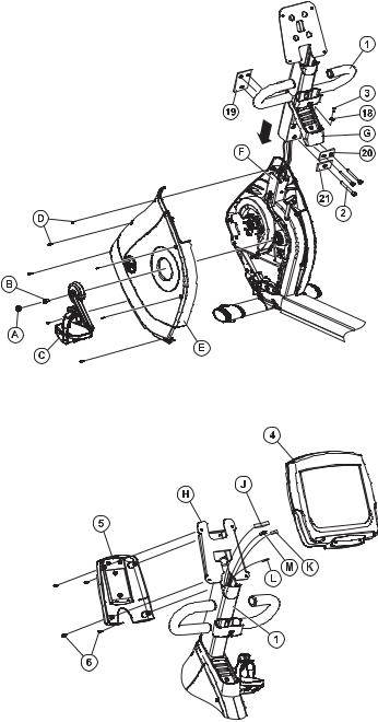
IMPORTANTE
NON GETTARE IL KIT DI IMBALLAGGIO, POICHÉ CONTIENE TUTTI I COMPONENTI
NECESSARI PER COMPLETARE L’INSTALLAZIONE.
1.Collocare la base dell’unità nell’ubicazione desiderata.
2.Rimuovere il TAPPO SUL FORO DELLA PEDIVELLA SINISTRA (A) e metterlo da parte. Rimuovere la VITE DELLA PEDIVELLA SINISTRA (B) e sfilare la PEDIVELLA (C)
dall’unità. Metterli da parte.
3.Rimuovere le sette VITI (D) che fissano la PROTEZIONE ANTERIORE SINISTRA (E). Rimuovere la PROTEZIONE ANTERIORE e metterla da parte.
4. Infilare il GRUPPO MONOCOLONNA (1) sopra IL TUBO ANTERIORE (F). Posizionare e allineare la PIASTRA PER DADI (19), la PIASTRA A DUE FORI (20) e la PIASTRA A UN FORO (21) sulle parti anteriore e posteriore del GRUPPO MONOCOLONNA come mostrato. Fissare il GRUPPO MONOCOLONNA con tre viti M10 x 90 mm (2). Serrare le VITI a una coppia di 50-55 lb-ft.
NOTA: quando si infila il GRUPPO MONOCOLONNA sopra il TUBO ANTERIORE, FARE ATTENZIONE A NON PIZZICARE
NESSUN FILO.
Installare nuovamente la PROTEZIONE ANTERIORE SINISTRA (E) usando le sette VITI (D) rimosse in
precedenza.
Installare nuovamente la PEDIVELLA (C) usando l’apposita VITE (B) rimossa in precedenza. Serrare le
VITI a una coppia di 30-33 lb-ft. Installare nuovamente il
TAPPO DEL FORO DELLA PEDIVELLA SINISTRA (A).
Fare scorrere il PORTA ACCESSORI ANTERIORE (G) verso il basso fino alle PROTEZIONI ANTERIORI (E). Fissare il PORTA ACCESSORI ANTERIORE con una VITE A CROCE (3) e una RONDELLA M5 (18). Serrare saldamente le VITI ma non eccessivamente.
5.Tagliare la fascetta che fissa i cavi alla STAFFA DELLA CONSOLE (H).
Posizionare la CONSOLE (4) accanto alla STAFFA DELLA CONSOLE (H). Collegare il CAVO PRINCIPALE DELLA CONSOLE (J), IL CAVO DI RETE
(K) e il CAVO DI MASSA (L) che escono dal GRUPPO MONOCOLONNA (1) alle rispettive posizioni sul pannello posteriore della CONSOLE.
NOTA: se si utilizza C-SAFE, collegare il CAVO DI RETE allo SPINOTTO NERO. Se si utilizza ETHERNET, collegare il CAVO DI RETE allo SPINOTTO ARGENTATO.
Per unità con console Engage (LCD da 15 pollici)
Collegare il CAVO COASSIALE (M)che esce dal GRUPPO MONOCOLONNA (1) al pannello posteriore della CONSOLE.
NOTA: assicurarsi che tutti i CONNETTORI siano saldamente inseriti.
Raggruppare tutti i cavi non utilizzati e fissarli con una fascetta sul lato del montante centrale della STAFFA DELLA CONSOLE. Fare attenzione a non ostruire i fori di montaggio.
Posare la CONSOLE sulla STAFFA DELLA CONSOLE. Posizionare la COPERTURA POSTERIORE (5) sul pannello posteriore della CONSOLE e fissarla con quattro VITI (6). Serrare saldamente le VITI ma non eccessivamente.
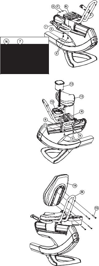
6.Posizionare i MANUBRI (7) come mostrato. Fissare ciascun MANUBRIO al TELAIO DEL SEDILE (N) con due VITI M8 x 20 mm (8) e due RONDELLE M8 (9).
NOTA: Prima di fissarli assicurarsi che le LINGUETTE dei MANUBRI siano inserite nelle fessure sul lato inferiore del TELAIO DEL SEDILE come mostrato nella figura di dettaglio.
COLLEGARE I cavi del cardiofrequenzimetro (O) che partono dai MANUBRI al CONDUTTORE CENTRALE (P) del TELAIO DEL SEDILE.
NOTA: Assicurarsi che i CONNETTORI siano saldamente inseriti.
7.Fissare il SUPPORTO DEL PORTA ACCESSORI (10) al TELAIO DEL SEDILE (N) con due VITI M8 x 16 mm (11) e due RONDELLE M8 (9). Serrare saldamente le VITI ma non eccessivamente.
Fissare il SEDILE (12) al TELAIO DEL SEDILE (N) con quattro VITI M8 x 20 mm (8) e due RONDELLE M8 (9). Serrare saldamente le VITI ma non eccessivamente.
Inserire il PORTA ACCESSORI (13) nel SUPPORTO DEL PORTA ACCESSORI come mostrato. Premere con forza verso il basso il PORTA ACCESSORI per fissarlo in posizione.
8.Fissare lo SCHIENALE DEL SEDILE (14) al TELAIO DEL SEDILE (N) con quattro VITI (15). Serrare saldamente le VITI ma non eccessivamente.
 Loading...