


8500 3-STACK MULTI-GYM
ASSEMBLY INSTRUCTIONS
Part # 6965401 1 Revision: 08/29/01
8500104
Rev. C
IMPORTANT NOTES
Please note:
*Thank you for purchasing the LIFE FITNESS 8500 MULTI-GYM. Please read these instructions thoroughly and keep them for future reference. This product must be assembled on a flat, level surface to assure its proper function.
*We recommend cleaning your product (pads and frame) on a regular basis, using warm soapy water. Touch-up paint can be purchased from your LIFE FITNESS customer service representative at (800) 328-9714.
There is a risk assumed by individuals who use this type of equipment. To minimize risk, please follow these rules:
1.Inspect equipment daily. Tighten all loose connections and replace worn parts immediately. Failure to do so may result in serious injury.
2.Do not allow minors or children to play on or around this equipment.
3.Exercise with care to avoid injury.
4.If unsure of proper use of equipment, call your local LIFE FITNESS STRENGTH distributor or call the LIFE FITNESS STRENGTH customer service department at (800) 328-9714.
5.Consult your physician before beginning any exercise program.
Tools Required for Assembly
*Rubber mallet or hammer
*3/4” wrench, 9/16” wrench
*Ratchet with 3/4” and 9/16” sockets
*5/32”, 3/16”, 7/32” Allen wrenches
*Adjustable wrench
*Tape measure
Bolt Length Ruler
NOTE: BOLT LENGTH IS MEASURED FROM THE UNDERSIDE OF THE HEAD OF THE BOLT.
BOLT LENGTH
BOLT LENGTH RULER:
|
1/2 |
|
1/2 |
|
1/2 |
|
1/2 |
|
1/2 |
|
|
1/2 |
|
|||||||||||
0 |
|
|
1 |
|
|
2 |
|
|
3 |
|
|
4 |
|
|
5 |
|
6 |
|||||||
|
|
|
|
|
|
|
|
|
|
|
|
|
|
|
|
|
|
|
|
|
|
|
|
|
2

PARTS LIST
KEY |
PART # |
DESCRIPTION |
QTY |
1 |
6617103 |
REARUPRIGHT |
1 |
2 |
6779802 |
LEG BACK PADADJUST |
1 |
3 |
6625502 |
LEG BACK PAD SUPPORT |
1 |
4 |
6624202 |
BACK PADANGLE LEFT |
1 |
5 |
6624302 |
BACK PADANGLE RIGHT |
1 |
6 |
6622903 |
PEC ARM RIGHT |
1 |
7 |
6623003 |
PEC ARM LEFT |
1 |
8 |
6623503 |
PRESS ARM |
1 |
9 |
6624502 |
CALF/LOW ROW |
1 |
10 |
6622503 |
BEARINGHOUSING |
1 |
11 |
6620903 |
FLOATINGPULLEYSTOP |
1 |
12 |
6691803 |
SEAT SUPPORT |
1 |
13 |
6692402 |
PAD SUPPORT |
1 |
14 |
6623702 |
WOLFFSLEEVE |
1 |
15 |
6662203 |
LEGEXTHANDLERIGHT |
1 |
16 |
6662303 |
LEGEXTHANDLELEFT |
1 |
17 |
6628302 |
2 X 8” PLATE |
1 |
18 |
6275302 |
LAT BAR |
1 |
19 |
6523401 |
72-3/8”GUIDEROD |
6 |
20 |
6765203 |
PRESS G.R. SUPPORT |
1 |
21 |
6765303 |
LEGG.R.SUPPORT |
1 |
22 |
6769903 |
PEC G.R. SUPPORT |
1 |
23 |
6768003 |
LEGWT. STACK BASE |
1 |
24 |
6767903 |
PRESS WT. STACK BASE |
1 |
25 |
6769003 |
BASE |
1 |
26 |
6769702 |
PULLEYBRACKET |
1 |
27 |
6769803 |
CENTERPULLEYBRACKET |
1 |
28 |
6772102 |
PEC CAM |
2 |
29 |
6768803 |
FRONTUPRIGHT |
1 |
30 |
6768503 |
TOP BOOM |
1 |
31 |
6769203 |
REARBASELEG |
1 |
32 |
6965503 |
LEGCURL/EXTENSION |
1 |
33 |
6872502 |
PADSLEEVE |
2 |
34 |
6771003 |
LEGFRAME |
1 |
35 |
6770102 |
SWIVELPULLEYBRACKET |
1 |
36 |
6871702 |
PRESS ARM ADJUST |
1 |
37 |
6768303 |
PRESS FRAME |
1 |
38 |
6770703 |
PRESSBASE |
1 |
39 |
6772201 |
19-1/4” TUBE |
1 |
40 |
6772301 |
21-1/2” TUBE |
1 |
41 |
6764901 |
4 X 7” ROLLER PAD |
8 |
42 |
6773101 |
LATCABLEASSEMBLY |
1 |
43 |
6962401 |
LEGCABLEASSEMBLY |
1 |
44 |
6773301 |
PRESSCABLEASSEMBLY |
1 |
45 |
6954901 |
ABCRUNCHCABLEASSEMBLY |
1 |
46 |
6773501 |
PECDECCABLEASSEMBLY |
1 |
47 |
3108002 |
WEIGHTSTACK CUSHION |
8 |
48 |
3116101 |
4-1/2”PULLEY |
24 |
49 |
3202301 |
PILLOWBLOCKBEARING |
2 |
50 |
6284501 |
20HOLESELECTORSHAFT |
3 |
51 |
6389701 |
LOW ROW CHROME BAR |
1 |
52 |
6619301 |
U-PIN |
1 |
53 |
6714601 |
HEAD PLATE |
3 |
54 |
3116001 |
1-1/4” SQ.RUBBER BUMPER |
3 |
55 |
6594702 |
FLOATINGPULLEYBRACKET |
1 |
56 |
6651602 |
2 X 15-1/2” PLATE |
2 |
57 |
6868702 |
4-1/2 X 8” PLATE |
1 |
58 |
6122702 |
3/8 X 1/2” SPACER |
2 |
59 |
3118401 |
4” VINYL CAP |
1 |
|
|
|
|
KEY |
PART # |
DESCRIPTION |
QTY |
60 |
6140701 |
1 X 1” GLIDE |
5 |
61 |
6177001 |
2-1/2 X 5-1/2 NON-SKID STRIP |
4 |
62 |
6412001 |
3/8 X 2-3/4” DIA. SPRING PIN |
6 |
63 |
6466901 |
1/2 X 3-1/2” DIA. SPRING PIN |
1 |
64 |
6954703 |
AB PULLEY PLATE |
2 |
65 |
6692601 |
3 X 2” END CAP |
2 |
66 |
6781601 |
1/2 X 7-7/8” SPRING PIN |
1 |
67 |
6757701 |
2-7/8 X 1” CABLE CLIP |
12 |
68 |
3103801 |
5/16” SNAP LINK |
4 |
69 |
6480301 |
3/8” FLANGE SPACER |
24 |
70 |
6020601 |
1/2” FLANGE BEARING |
4 |
71 |
3104901 |
3/4” FLANGE BEARING |
6 |
72 |
6619501 |
3/4” SLEEVE BEARING |
2 |
73 |
3109602 |
1/2” PAL NUT |
1 |
74 |
6075906 |
12 LINK CHAIN |
1 |
75 |
6214401 |
WEIGHT STACK PIN |
3 |
76 |
6406401 |
HINGE TAB |
4 |
77 |
6695001 |
3/4” DIA. TAPPED SHAFT |
1 |
78 |
3103302 |
13/16” SHAFT COLLAR |
6 |
79 |
3103304 |
1-5/16” SHAFT COLLAR |
8 |
80 |
3102501 |
3/8” WASHER |
67 |
81 |
3114502 |
3/8” LOCK WASHER |
5 |
82 |
3102802 |
3/8” LOCK NUT |
41 |
83 |
3102807 |
3/8” LOW HEIGHT LOCK NUT |
3 |
84 |
3102502 |
1/2” WASHER |
21 |
85 |
3102801 |
1/2” LOCK NUT |
24 |
86 |
3102804 |
1/2” LOW HEIGHT LOCK NUT |
8 |
87 |
3202401 |
3/8 X 1” BTTN HD CAP SCREW |
4 |
88 |
3102901 |
3/8 X 1-1/4” BOLT |
15 |
89 |
3102933 |
3/8 X 2” BOLT |
14 |
90 |
3102922 |
3/8 X 2-3/4” BOLT |
16 |
91 |
3102915 |
3/8 X 3-1/4” BOLT |
16 |
92 |
3102906 |
3/8 X 4” BOLT |
4 |
93 |
3202101 |
1/2 X 1-1/4” BOLT |
2 |
94 |
3102910 |
1/2 X 3” BOLT |
7 |
95 |
3102918 |
1/2 X 3-1/4” BOLT |
8 |
96 |
3102917 |
1/2 X 4” BOLT |
10 |
97 |
3202107 |
1/2 X 6-1/2” BOLT |
2 |
98 |
3202105 |
1/2 X 7-1/2” BOLT |
1 |
99 |
6780101 |
PEC ARM PAD |
2 |
100 |
6780001 |
PRESS SEAT PAD |
1 |
101 |
6780301 |
PRESS BACK PAD |
1 |
102 |
6780201 |
LEG SEAT PAD |
1 |
103 |
6780401 |
LEG BACK PAD |
1 |
104 |
6780601 |
PEC SEAT PAD |
1 |
105 |
6780501 |
PEC BACK PAD |
1 |
106 |
6214501 |
WEIGHT PLATE |
60 |
107 |
6703801 |
WEIGHT PLATE LABELS (LBS.) |
1 |
108 |
6189501 |
WEIGHT PLATE LABELS (1-25) |
1 |
109 |
6382301 |
WEIGHT PLATE BUSHING (10 CT) |
12 |
110 |
6375801 |
AB CRUNCH STRAP |
1 |
111 |
6779703 |
LEG SHROUD |
1 |
112 |
6779503 |
PEC SHROUD |
1 |
113 |
6779601 |
PRESS SHROUD |
1 |
114 |
3102909 |
3/8 X 1” BOLT |
12 |
115 |
3108404 |
3/8 X 3” COUNTERSUNK BOLT |
2 |
116 |
6827001 |
2-7/8 X 2-1/4” CABLE CLIP |
8 |
118 |
6122704 |
1/4” SPACER |
4 |
|
|
|
|
3
|
23 |
1/2 X 3-1/4” 95 |
|
|
25 |
61 |
24 |
|
85 |
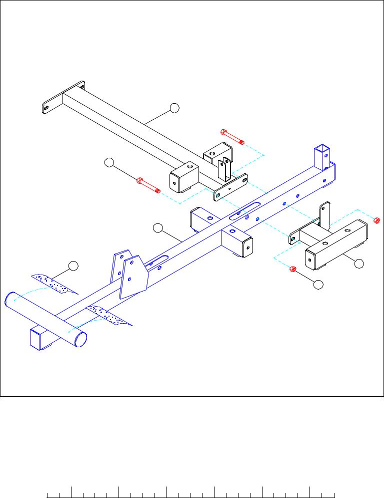
FIGURE 1 |
|
STEP 1:
•LOOSELY assemble the LEG WEIGHT STACK BASE (23) and the PRESS WEIGHT STACK BASE (24) to the BASE (25) using two 1/2 X 3-1/4” BOLTS (95) and two 1/2” LOCK NUTS (85) as shown in FIGURE 1.
•Apply two NON-SKID STRIPS (61) to the BASE (25) as shown in FIGURE 1.
|
1/2 |
|
1/2 |
|
1/2 |
|
1/2 |
|
1/2 |
|
|
1/2 |
0 |
1 |
2 |
3 |
4 |
5 |
6 |
||||||
4
96 1/2 X 4””
84
|
30 |
85 |
85 |
|
95 1/2 X 3-1/4”
1
29
85
84
94 1/2 X 3”
85 |
25 |
95 1/2 X 3-1/4”
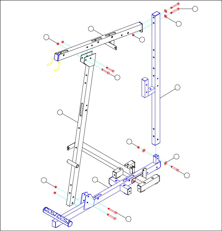
FIGURE 2
STEP 2:
•LOOSELY assemble the FRONT UPRIGHT (29) to the BASE (25) using two 1/2 X 3-1/4” BOLTS (95) and two 1/2” LOCK NUTS (85) as shown in FIGURE 2.
•LOOSELY assemble the REAR UPRIGHT (1) to the BASE (25) using one 1/2 X 3” BOLT (94), two 1/2” WASHERS (84), and one 1/2” LOCK NUT (85) as shown in FIGURE 2.
•LOOSELY assemble the TOP BOOM (30) to the REAR UPRIGHT (1) using two 1/2 X 4” BOLTS (96), two 1/2” WASHERS (84), and one 1/2” LOCK NUT (85) as shown in FIGURE 2.
•LOOSELY assemble the TOP BOOM (30) to the FRONT UPRIGHT (29) using two 1/2 X 3-1/4” BOLTS (95) and two 1/2” LOCK NUTS
(85)as shown in FIGURE 2.
TIGTEN ALL LOOSE FRAME CONNECTIONS MADE TO THIS POINT! 5

105 |
|
|
|
29 |
|
|
92 3/8 X 4” |
|
|
80 |
|
104 |
|
|
13 |
1/2” |
|
|
||
80 |
LOW |
|
HEIGHT 86 |
||
|
||
3/8 X 1-1/4” 88 |
11 |
|
1/2 X 4” 96 |
|
|
12 |
|
|
|
62 |
|
FIGURE 3 |
|
STEP 3:
•SECURELY assemble the FLOATING PULLEY STOP (11) and the SEAT SUPPORT (12) to the FRONT UPRIGHT (29) using two 1/2 X 4” BOLTS (96) and two 1/2” LOW HEIGHT LOCK NUTS (86) as shown in FIGURE 3.
•SECURELY assemble one 3/8 X 2-3/4” SPRING PIN (62) to the SEAT SUPPORT (12) as shown in FIGURE 3.
•SECURELY assemble one PEC SEAT PAD (104) to the PAD SUPPORT (13) using two 3/8 X 1-1/4” BOLTS (88) and two 3/8” WASHERS
(80)as shown in FIGURE 3.
•CAREFULLY insert the PAD SUPPORT (13) into the SEAT SUPPORT (12) and engage the SPRING PIN into one of the holes.
•SECURELY assemble one PEC BACK PAD (105) to the FRONT UPRIGHT (29) using two 3/8 X 4” BOLTS (92) and two 3/8” WASHERS
(80)as shown.
|
1/2 |
|
1/2 |
|
1/2 |
|
1/2 |
|
1/2 |
|
|
1/2 |
|
|||||||||||
0 |
|
|
1 |
|
|
2 |
|
|
3 |
|
|
4 |
|
|
5 |
|
6 |
|||||||
|
|
|
|
|
|
|
|
|
|
|
|
|
|
|
|
|
|
|
|
|
|
|
|
|
6

|
|
|
60 |
|
|
1/2 X 4” 96 |
|
|
|
|
10 |
|
29 |
27 86 |
|
|
|
||
|
|
|
|
1/2” |
|
|
|
|
LOW HEIGHT |
|
|
|
79 |
|
|
|
72 |
41 |
|
|
|
|
|
|
|
|
|
40 |
|
|
|
|
28 |
|
7 |
71 |
|
|
|
|
71 |
|
6 |
|
|
84 |
|
|
|
|
|
|
|
|
|
85 |
|
|
|
|
62 |
|
99 |
|
|
|
|
|
|
|
|
80 |
|
|
FIGURE 4 |
3/8 X 3-1/4” 91 |
|
|
|
|
|
|
|
STEP 4:
•SECURELY assemble the BEARING HOUSING (10) and the CENTER PULLEY BRACKET (27) to the FRONT UPRIGHT (29) using two 1/2 X 4” BOLTS (96) and two 1/2” LOW HEIGHT LOCK NUTS (86).
•Assemble the RIGHT PEC ARM (6) and one PEC CAM (28) to the BEARING HOUSING (10) using one 3/4” SLEEVE BEARING (72), two 3/4” FLANGE BEARINGS (71), one 1/2” WASHER (84), and one 1/2” LOCK NUT (85) as shown in FIGURE 4. (NOTE: SECURELY tighten, then back nut off 1/4 turn to allow the PEC ARM to rotate freely.)
•Assemble the LEFT PEC ARM (7) and one PEC CAM (28) to the BEARING HOUSING (10) using one 3/4” SLEEVE BEARING (72), two 3/4” FLANGE BEARINGS (71), one 1/2” WASHER (84), and one 1/2” LOCK NUT (85) as shown in FIGURE 4. (NOTE: SECURELY tighten, then back nut off 1/4 turn to allow the PEC ARM to rotate freely.)
•SECURELY assemble a 3/8 X 2-3/4” SPRING PIN (62) to the to the RIGHT & LEFT PEC ARM (6 & 7). See FIGURE 4.
•Apply two 1” X 1” GLIDES (60) to the BEARING HOUSING (10) where the PEC CAMS (28) come in contact with the BEARING HOUSING
(10)as shown.
•SECURELY assemble one PEC ARM PAD (99) to both the RIGHT & LEFT PEC ARMS (6 & 7) using four 3/8 X 3-1/4” BOLTS (91) and four 3/8” WASHERS (80). See FIGURE 4.
•SECURELY assemble two 4 X 7” ROLLER PADS (41) to the FRONT UPRIGHT (29) using one 21-1/2” TUBE (40) and two 1-5/16” SHAFT COLLARS (79). SECURELY tighten set screws on SHAFT COLLARS (79). See FIGURE 4.
7
|
73 |
|
14 |
|
37 |
|
59 |
62 |
52 |
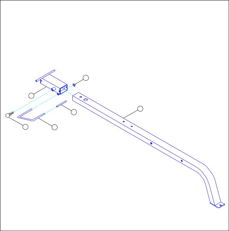
FIGURE 5 |
|
STEP 5:
•SECURELY assemble one 3/8 X 2-3/4” SPRING PIN (62) to the WOLFF SLEEVE (14) as shown in FIGURE 5.
•Assemble one U-PIN (52) to the WOLFF SLEEVE (14) using one 1/2” PAL NUT (73).
•Slide one 4” VINYL SLEEVE (59) onto the U-PIN (52) as shown in FIGURE 5.
•CAREFULLY slide the WOLFF SLEEVE (14) onto the PRESS FRAME (37) until the SPRING PIN engages in one of the holes.
|
1/2 |
|
1/2 |
|
1/2 |
|
1/2 |
|
1/2 |
|
|
1/2 |
|
|||||||||||
0 |
|
|
1 |
|
|
2 |
|
|
3 |
|
|
4 |
|
|
5 |
|
6 |
|||||||
|
|
|
|
|
|
|
|
|
|
|
|
|
|
|
|
|
|
|
|
|
|
|
|
|
8

|
94 1/2 X 3” |
|
38 |
|
1 |
|
84 |
|
85 |
|
86 1/2” LOW HEIGHT |
94 1/2 X 3” |
35 |
|
84 |
|
85 |
25 |
|
FIGURE 6 |
|
STEP 6:
•SECURELY assemble the PRESS BASE (38) to the BASE (25) using two 1/2 X 3” BOLTS (94), two 1/2” WASHERS (84), and two 1/2” LOCK NUTS (85), and to the REAR UPRIGHT (1) using one 1/2 X 3” BOLT (94), one 1/2” WASHER (84), and one 1/2” LOCK NUT (85) as shown in FIGURE 6.
•Assemble the SWIVEL PULLEY BRACKET (35) to the PRESS BASE (38) using one 1/2” LOW HEIGHT LOCK NUT (86) as shown in FIGURE 6. (NOTE: Securely tighten, then back nut off 1/4 turn to allow the SWIVEL PULLEY BRACKET to rotate freely.)
9

94 1/2 X 3” |
|
84 |
115 3/8 X 3” COUNTER SUNK |
|
|
37 |
57 |
|
|
84 |
|
85 |
|
38 |
|
|
80 |
|
82 |
FIGURE 7 |
|
STEP 7:
•SECURELYassemble the PRESS FRAME (37) to the PRESS BASE (38) using one 1/2” X 3” BOLT(94), two 3/8 X 3” COUNTERSUNK BOLTS (115), one 4-1/2” X 8” PLATE (57), two 1/2” WASHERS (84), two 3/8” WASHERS (80), one 1/2” LOCK NUT(85), and two 3/8” LOCK NUTS (82). (NOTE: Make sure 3/8” countersunk bolts are facing down.) See FIGURE 7.
|
1/2 |
|
1/2 |
|
1/2 |
|
1/2 |
|
1/2 |
|
|
1/2 |
0 |
1 |
2 |
3 |
4 |
5 |
6 |
||||||
10
|
101 |
|
80 |
3/8 X 1-1/4” 88 |
5 |
|
|
|
1/2” |
|
LOW |
|
86 HEIGHT |
54 |
84 |
|
|
1/2 X 1-1/4” 93 |
|
37 |
|
116 |
85 |
|
100 |
4 |
|
38 |
|
14 |
|
76 |
|
80 |
|
3/8 X 1-1/4” 88 |
|
97 1/2 X 6-1/2” |
|
FIGURE 8 |
|
STEP 8:
•Slide two HINGE TABS (76) onto the WOLFF SLEEVE (14) and SECURELY attach PRESS SEAT PAD (100) using two 3/8 X 1-1/4” BOLTS (88) and two 3/8” WASHERS (80). (NOTE: The “hinge” part of the HINGE TAB (76) should face upward as shown in
FIGURE 8.)
•Slide the RIGHT BACK PAD ANGLE (5) and LEFT BACK PAD ANGLE (4) onto the WOLFF SLEEVE (14) and attach the PRESS BACK PAD (101) using four 3/8 X 1-1/4” BOLTS (88) and four 3/8” WASHERS (80). See FIGURE 8.
•SECURE two 2 X 15-1/2” PLATES (56) to the RIGHT BACK PAD ANGLE (5) and the LEFT BACK PAD ANGLE (4) using two 1/2 X 1- 1/4” BOLTS (93), two 1/2” WASHERS (84) and two 1/2” LOW HEIGHT LOCK NUTS (86). (NOTE: SECURE lock nuts, then back off
1/4 turn.)
•SECURE the 2 X 15-1/2” PLATES (56) to the bushing in the PRESS BASE (38) using one 1/2 X 6-1/2” BOLT (97) and one 1/2” LOCK NUT (85) as shown in FIGURE 8.
•Apply one 1-1/4” RUBBER BUMPER (54) to the PRESS FRAME (37) where the back of the pad comes in contact with the frame.
11
 Loading...