


Models 8500, 9100, and 9500HR
Total Body Cross-Trainers with Rear Drive System
Customer Support Services
SERVICE MANUAL

Life Fitness Models 8500, 9100, and 9500HR Cross-Trainers
INTRODUCTION
HOW TO USE THIS SERVICE MANUAL AND CONTACT CUSTOMER SUPPORT SERVICES
This service manual is applicable to Cross-Trainer Models CT8500, CT9100, and CT9500HR. Note: Information represents typical configuration and may differ slightly from actual equipment. The Service Manual provides recommendations for safe and efficient approaches to problem situations. This manual is separated into six sections.
INTRODUCTION
THEORY OF OPERATION
TERMINOLOGY
TABLE OF CONTENTS
Section I
qTROUBLESHOOTING GUIDES Section II
qDIAGNOSTIC TESTS
Section III
q"How To..." SERVICE AND REPAIR GUIDES Section IV
qELECTRONICS OVERVIEW
qWIRING BLOCK DIAGRAMS
Section V
qPARTS IDENTIFICATION Section VI
qMISCELLANEOUS INFORMATION
Refer to TABLE OF CONTENTS for section topics.
When an operating problem occurs, refer to troubleshooting guides and diagnostic tests in an attempt to isolate the cause. When applicable, guides and tests are listed by symptom followed with suggestions of probable cause(s).
Once you have pinpointed the source of the problem, refer to "How To..." guides for recommended repair procedures. "How To..." sub-sections are organized by replaceable part or assembly name. For convenience, sub-section lists recommended “Tools Required” to complete each specific function.
Refer to the PARTS IDENTIFICATION section to identify proper name and number of part to order for repair of equipment.
A reproducible telefacsimile order claim form is provided in COMMUNICATING BY TELEFACSIMILE for convenient ordering of service parts.
To order, contact Life Fitness Customer Support Services.
Via telefacsimile - 24 hrs. /day, 7 days/week.
Via telephone - Monday through Friday from 8:00 AM to 7:00 PM ( C.S.T.).
To speed Life Fitness Customer Support Services response to your needs, please be prepared to provide the following information to the phone technician.
1.Model number
2.Serial number consists of 3 letters and 6 numbers
3.Symptom of problem
4.Part name and number to order (if known)
Before installing a part, review "How To..." and follow the step by step procedures recommended to install the part safely and efficiently. If you have questions or comments, please telephone, FAX or write us. We are:
LIFE FITNESS - CUSTOMER SUPPORT SERVICES 10601 Belmont Avenue; Franklin Park, IL 60131; U.S.A. Telephone: 847.451.0036 or Toll Free 800.351.3737 FAX: 847.288.3702 or Toll Free 800.216.8893

Life Fitness Models 8500, 9100, and 9500HR Cross-Trainers
THEORY OF OPERATION
The electronic system on the rear-drive crosstrainer is made up of three main functional blocks: 1) Console, 2) HR telemetry, and 3) Alternator, Power Control Board, and Load. In addition, the 9500 model has Lifepulse contact HR. The following is a description of each functional block:
CONSOLE
The system voltage (6-7.5Vdc) enters on connector P2 pin 1 and is used to power the LEDs and provide a supply voltage for the 5V-regulator circuitry used to power the microprocessor section.
The Keypad entry (user’s input), Lifepulse (9500HR only), and Telemetry are all processed by the microprocessor. The console outputs a PWM signal to the power control board to control the duty cycle of the load.
ALTERNATOR, POWER CONTROL BOARD, AND LOAD
Using the PWM signal from the console, the power control board switches the current on and off at the load via Q1. The control board also regulates the alternator voltage using the U1 comparitors. Q3 and Q9 are used to sense the reed switch actuation (autostart feature).
POLAR
HR telemetry is implemented via a Polar receiver located in the rocker arm shroud at the front of the unit. The Polar receiver connects to the console at connector P7.
LIFEPULSE (9500 ONLY)
The handlebar electrodes connect to the console board at connector P9. Pins 1 and 4 are signal, pins 2 and 3 are circuit reference.

Life Fitness Models 8500, 9100, and 9500HR Cross-Trainers
TERMINOLOGY
The following words and acronyms are commonly referred to throughout this manual. Take time to familiarize yourself with them.
Connectors |
Electrical plugs used to connect wiring into electrical component. |
|
|
Display Console |
Electronic board for making settings and monitoring physical output. |
Board |
|
|
|
DSP |
Disgital system processing. |
|
|
EEPROM |
Electrically errasible programmable read only memory. |
|
|
EEROM |
Electrically errasible read only memory. |
|
|
LDC |
Load duty cycle. |
|
|
LED |
Light emitting diode used to show a state of operation. |
|
|
LifePulse |
Heart rate sensors on hand grips. |
|
|
PCB |
Power control board regulates voltage to alternator, console, and battery. |
|
|
Polar Receiver |
A device directly in front of the operator that monitors heart rate. |
|
|
Rear drive |
The area where all the drive components reside. |
|
|
RPM |
Revolutions per minute describes the amount of times something turns within a minute of |
|
time. |
|
|

Life Fitness Models 8500, 9100, and 9500HR Cross-Trainers
TABLE OF CONTENTS
SECTION I |
|
TROUBLESHOOTING GUIDES |
PAGE |
GRINDING, RUBBING, KNOCKING NOISE..................................................................... |
2 |
DRIVE BELT SLIPPING ................................................................................................ |
3 |
UPPER ARMS LOOSE................................................................................................. |
3 |
PLAY IN PEDAL LEVER............................................................................................... |
3 |
NO LOAD .................................................................................................................... |
3 |
NO LEDS ON DISPLAY ................................................................................................ |
3 |
ALTERNATOR BELT SLIPPING..................................................................................... |
4 |
NO HEART RATE OR ERRATIC HEART RATE ............................................................... |
4 |
NO LEDS or RANDOM LEDS LIT................................................................................... |
5 |
NO RPM...................................................................................................................... |
5 |
AUTO START FAILURE ................................................................................................ |
5 |
NOTES........................................................................................................................ |
6 |
SECTION II |
|
DIAGNOSTIC MODES |
|
DISPLAY CONSOLES .................................................................................................. |
2 |
ENTERING DIAGNOSTIC STATES 1-17 ......................................................................... |
3 |
DIAGNOSTIC STATE 1: LEDS AND KEYPAD TEST........................................................ |
4 |
DIAGNOSTIC STATE 2: INDIVIDUAL LED TEST.............................................................. |
5 |
DIAGNOSTIC STATE 3: CODE VERSION/RPM/HEART RATE/LDC TESTS....................... |
6 |
DIAGNOSTIC STATE 3: CODE VERSION/RPM/NETWORKING/LDC TESTS |
|
(DISPLAY LOCK EQUIPPED MODEL ONLY)......................................... |
7 |
DIAGNOSTIC STATE 4: FIELD/ALTERNATOR – REGULATOR TEST................................ |
8 |
DIAGNOSTIC STATE 5: PROGRAM VERSION AND NETWORKING TEST ....................... |
9 |
DIAGNOSTIC STATE 5: LIFEPULSE TEST |
|
(DISPLAY LOCK EQUIPPED MODEL ONLY)......................................... |
10 |
DIAGNOSTIC STATE 6: MAXIMUM WORKOUT DURATION ............................................. |
11 |
DIAGNOSTIC STATE 7: TELEMETRY ON/OFF............................................................... |
12 |
DIAGNOSTIC STATE 8: ENGLISH / METRIC UNITS ........................................................ |
13 |
DIAGNOSTIC STATE 9: POWER SUPPLY TYPE ........................................................... |
14 |
DIAGNOSTIC STATE 10: SHUTDOWN TIME .................................................................. |
15 |
DIAGNOSTIC STATE 11: PROGRAM TIME .................................................................... |
16 |
DIAGNOSTIC STATE 12: STATISTICS............................................................................ |
17 |
DIAGNOSTIC STATE 13: METS ENABLE / DISABLE ...................................................... |
18 |
DIAGNOSTIC STATE 14: KEYPAD SELECTION ............................................................. |
19 |
DIAGNOSTIC STATE 15: TOGGLE ENABLE / DISABLE.................................................. |
20 |
DIAGNOSTIC STATE 16: PHOTOSHOOT....................................................................... |
21 |
DIAGNOSTIC STATE 16: LANQUAGE CONFIGURATION |
|
(DISPLAY LOCK EQUIPPED MODEL ONLY)......................................... |
22 |
DIAGNOSTIC STATE 17: PHOTOSHOOT |
|
(DISPLAY LOCK EQUIPPED MODEL ONLY)......................................... |
23 |
NOTES........................................................................................................................ |
24 |

Life Fitness Models 8500, 9100, and 9500HR Cross-Trainers
TABLE OF CONTENTS – Continued
SECTION III |
|
HOW TO...REPLACE THE: |
|
DISPLAY CONSOLE .................................................................................................... |
2 |
ACCESSORY TRAY (OPTIONAL ON CT8500) ................................................................ |
3 |
DISPLAY CONSOLE SUPPORT ASSEMBLY ................................................................. |
4 |
REAR COVERS ........................................................................................................... |
5 |
CRANKARM ROLLER ASSEMBLY AND COVER ........................................................... |
6 |
CRANKARM ASSEMBLY ............................................................................................. |
7 |
DRIVE BELT AND ALTERNATOR BELT......................................................................... |
8 |
POWER CONTROL BOARD ASSEMBLY....................................................................... |
9 |
ALTERNATOR.............................................................................................................. |
10 |
ALTERNATOR BELT..................................................................................................... |
11 |
PEDAL LEVER ASSEMBLY ......................................................................................... |
12 |
ROCKER ARMS........................................................................................................... |
13 |
TIE ROD ...................................................................................................................... |
14 |
CRANKSHAFT PULLEY ASSEMBLY............................................................................. |
15 |
INTERMEDIATE PULLEY.............................................................................................. |
16 |
LOAD RESISTORS....................................................................................................... |
17 |
USER ARMS ............................................................................................................... |
18 |
POLAR RECEIVER ...................................................................................................... |
19 |
MONOCOLUMN COVER............................................................................................... |
20 |
FRAME COVER........................................................................................................... |
21 |
FRONT COVER............................................................................................................ |
22 |
BATTERY .................................................................................................................... |
23 |
REAR WHEELS AND AXLE .......................................................................................... |
24 |
ENDCAPS ................................................................................................................... |
25 |
PEDAL ....................................................................................................................... |
26 |
SET JUMPERS ON CSAFE CARD ................................................................................ |
27 |
NOTES........................................................................................................................ |
28 |
SECTION IV |
|
ELECTRONICS OVERVIEW / WIRING DIAGRAM |
|
DISPLAY CONSOLE BOARD........................................................................................ |
2 |
POWER CONTROL BOARD.......................................................................................... |
4 |
ALTERNATOR.............................................................................................................. |
5 |
WIRING BLOCK DIAGRAM ........................................................................................... |
6 |
NOTES........................................................................................................................ |
7 |

Life Fitness Models 8500, 9100, and 9500HR Cross-Trainers
TABLE OF CONTENTS – Continued
SECTION V |
|
PARTS IDENTIFICATION |
|
MODEL IDENTIFICATION and SERIAL NUMBER LOCATION ........................................... |
2 |
CT 8500....................................................................................................................... |
3 |
CT 9100....................................................................................................................... |
5 |
CT 9500 - 15 ................................................................................................................ |
7 |
CT 9500 - 17 ................................................................................................................ |
9 |
NOTES........................................................................................................................ |
11 |
SECTION VI |
|
MISCELLANEOUS INFORMATION |
|
PREVENTIVE MAINTENANCE TIPS .............................................................................. |
2 |
INSTALLATION INSTRUCTIONS .................................................................................... |
3 |
UNPACKING INSTRUCTIONS........................................................................................ |
9 |
COMMUNICATING BY FAX........................................................................................... |
10 |
NOTES........................................................................................................................ |
12 |

© 2000 Life Fitness, a division of Brunswick Corporation. All rights reserved. Life Fitness, Lifecycle, and Lifepulse are registered trademarks, and Heart Rate Zone Training and RELY ON IT are trademarks of Brunswick Corporation. Polar is a registered trademark of Polar Electro, Inc.
Any use of these trademarks without the express written consent of Life Fitness or the corresponding companies is forbidden.
M051-00K61-B014 07/00

Life Fitness Model 8500, 9100, and 9500HR Cross-Trainers
Section I
SECTION I
TROUBLESHOOTING
GUIDES
1

Life Fitness Model 8500, 9100, and 9500HR Cross-Trainers
Malfunction
Grinding, rubbing, knocking noises when pedal levers rotate under load.
|
Probable Cause |
|
Corrective Action |
|
|
Pulleys misaligned. |
|
Loosen the pillow block bearings, |
|
|
|
|
realign the pulleys, and retighten the |
|
|
|
|
pillow block bearings. |
|
|
|
|
|
|
|
Dirt build up in pedal tracks. |
|
Clean and remove dirt build up. |
|
|
|
|
|
|
|
Rear roller wheels frozen. |
|
Clean and lubricate with non |
|
|
|
|
detergent oil. |
|
|
|
|
|
|
|
|
|
|
|
|
Link cover contacting rear cover. |
|
Reposition rear cover(s) or replace. |
|
|
|
|
|
|
|
|
|
Check that the inner link cover |
|
|
|
|
mounting screws are properly |
|
|
|
|
installed. |
|
|
|
|
|
|
|
Excessive disk wobble. |
|
Make sure no weld interference |
|
|
|
|
occurs between the crankarm and |
|
|
|
|
the disk cover. |
|
|
|
|
|
|
|
|
|
Ensure that the crankshaft is flush |
|
|
|
|
with the crankarm and check for |
|
|
|
|
proper alignment. See How To. |
|
|
|
|
|
|
|
Faulty intermediate shaft assembly. |
|
Replace intermediate shaft assy. |
|
|
|
|
|
|
|
Faulty pillow block. |
|
Replace pillow blocks on crankshaft. |
|
|
|
|
|
|
|
Alternator. |
|
Relieve tension on alternator, spin |
|
|
|
|
flywheel for smoothness. If |
|
|
|
|
thumping occurs, faulty alternator. |
|
|
|
|
Replace alternator. |
|
|
|
|
|
|
|
Bearings at pivot points are out of |
|
Clean all sleeves in the linkage pivot |
|
|
position or dirty. |
|
areas and lubricate with non |
|
|
|
|
detergent oil. |
|
|
|
|
|
|
|
|
|
|
|
|
Setscrews or crankarm bolt in |
|
Loosen setscrew and clamping |
|
|
crankarm assembly are loose. |
|
screw in crankarm assembly. Apply |
|
|
|
|
blue Loctite® (242) on screw threads. |
|
|
|
|
Tighten setscrew first to set keyway, |
|
|
|
|
then tighten clamping screw. |
|
|
|
|
Crankarm bolt requires no Loctite. |
|
|
|
|
|
|
|
Small extension arm bolt loose. |
|
Replace small extension arm kit. |
|
|
|
|
|
|
|
Faulty link bearings. |
|
Replace link assembly. |
|
|
|
|
|
|
2
|
Link mounting loose. |
Clean, lubricate, and retighten. |
3

Life Fitness Model 8500, 9100, and 9500HR Cross-Trainers
Malfunction |
Probable Cause |
Corrective Action |
Grinding, rubbing, knocking noises |
Excessive end play in rocker arms. |
Adjust collars as necessary to take |
when pedal levers rotate under |
|
out the end play. See How To |
load. |
|
Replace Rocker Arms. |
|
|
|
|
Pedal lever vibrates or squeaks during |
Align pedal lever. See How To |
|
operation. |
Replace Pedal Lever. |
|
|
|
|
Pedal tape not adhering properly. |
See How To Replace Pedal Lever |
|
|
|
Drive Belt slipping. |
Loose or worn belt. |
Check belt tension using a J10 belt |
|
|
gauge. The belt deflection should be |
|
|
1/4’ (7mm) at 170 lb for a new belt |
|
|
and 160 lb for an existing belt. |
|
|
|
Upper Arms feel loose. |
Bolts that connect the upper and |
Adjust and tighten to a torque of 30- |
|
lower arms are loose. |
35 ft lb. |
|
|
|
Front to back play in pedal lever. |
Worn bearings. |
Check for front to back movement in |
|
|
bearings that connect pedal lever to |
|
|
the rocker arm. Replace pedal lever |
|
|
assembly. |
|
|
|
|
Poly V-Pulley on intermediate shaft is |
Replace intermediate shaft |
|
loose. |
assembly. |
|
|
|
|
Crankarm loose. |
Loosen setscrews and clamping |
|
|
screw in Crankarm Assembly. Apply |
|
|
blue Loctite® 242 on screws. Tighten |
|
|
setscrews first and then tighten the |
|
|
clamping screw. |
|
|
|
|
Worn link bearings. |
Replace link. |
|
|
|
|
Loose link mounting. |
Clean, lube, and reassemble. |
|
|
|
No Load. |
Faulty cables, power console board, |
Enter diagnostic state 3 and execute |
|
or alternator. |
the field duty cycle and increase the |
|
|
load. If load does not increase, |
|
|
replace alternator. |
|
|
|
No LEDs on display. |
Faulty display console. |
Using a voltmeter, verify 8Vdc at the |
|
|
10 position Molex connector pin 1 on |
|
|
the display console PCB. If voltage |
|
|
is present, replace display console. |
|
|
If not, replace power control board. |
|
|
|
Section I
4
|
Faulty power control board. |
Using a voltmeter, verify 8Vdc at 11 |
|
|
position connector pin 4 on the |
|
|
power control board. If present, |
|
|
replace console cable. If not, replace |
|
|
board. |
5

Life Fitness Model 8500, 9100, and 9500HR Cross-Trainers
Malfunction |
Probable Cause |
Corrective Action |
Alternator belt slipping. |
Belt is loose. |
Retension from 65-70 lb. |
|
|
|
No heart rate or erratic heart rate. |
Pinched cable in Monocolumn cover. |
Remove monocolumn covers and |
|
|
inspect cables. Replace damaged |
|
|
cable. |
|
|
|
|
Defective chest strap or improperly |
Replace chest strap or reposition it. |
|
positioned. |
Reset transmitter. Refer to |
|
|
Diagnostics state 3 to execute the |
|
|
heart rate test. |
|
|
|
|
No heart rate reading. |
Execute Diagnostic Mode to verify |
|
|
performance of heart rate function. |
|
|
|
|
Faulty cable connection. |
Verify heart-rate cable is properly |
|
|
connected. Using an ohmmeter, |
|
|
verify continuity at the main console |
|
|
cable. |
|
|
|
|
Malfunctioning user arm/Lifepulse |
Replace user arm/Lifepulse |
|
(CT9500HR) Grip Assembly (include |
(CT9500HR) Assembly. |
|
worn or damaged heart rate lead). |
|
|
|
|
|
Life Pulse user arm defective. |
Verify user arm is functioning. Wipe |
|
|
sensors dry. Using an ohmmeter, |
|
|
verify continuity between Lifepulse |
|
|
sensor and cable connection. |
|
|
Replace if defective. |
|
|
|
|
Loose or malfunctioning heart rate |
Secure connection. Replace |
|
lead connection at Display Console. |
malfunctioning user arm/Lifepulse |
|
|
(CT9500HR) Grip Assembly. |
|
|
|
|
Heart-rate (DSP) Board (CT9500HR) |
Verify that the heart-rate (DSP) |
|
is faulty or not communicating. |
board (CT9500HR) is communi- |
|
|
cating. If defective, replace. |
|
|
|
|
Malfunctioning Display Console. |
Test with known good Display |
|
|
Console. Replace malfunctioning |
|
|
Display Console. |
|
|
|
|
Cross talk from telemetry and another |
Position Cross-Trainer at least 3 ft |
|
transmitter or possible interference |
(1 m) from unit with telemetry or from |
|
from other electronic devices. |
other electronic devices. |
|
|
|
|
Bad connection. |
Check for corrosion on connectors. |
|
|
Disconnect and reconnect telemetry |
|
|
receiver. |
6
7

Life Fitness Model 8500, 9100, and 9500HR Cross-Trainers
Malfunction |
Probable Cause |
Corrective Action |
No LEDs or random LEDs lit. |
Cable connection faulty. |
Remove display console and verify |
|
|
cable is properly plugged into |
|
|
console. |
|
|
|
|
Main wire harness damaged. |
Check for a damaged wire harness. |
|
|
Replace wire harness. |
|
|
|
No RPM. Unit shuts off one minute |
Bad cable connection. |
Verify cables connections at console |
into program. |
|
to power control PCB, and power |
|
|
control PCB to alternator. |
|
|
Disconnect and reconnect cables. |
|
|
Using a voltmeter, verify cable |
|
|
continuity on console to power |
|
|
control PCB and power control PCB |
|
|
to alternator. |
|
|
|
Auto start failure |
No RPM |
Operator must be pedling unit for the |
|
|
auto start feature to activate. |
|
|
|
|
Battery |
Battery voltage should be 5.8 – 6.3 |
|
|
Vdc. If not, replace the battery. |
|
|
|
|
Bad cable connection. |
Verify cables connections at |
|
|
console, board, and reed switch are |
|
|
correct and connected properly. |
|
|
|
|
Magnet |
Verify that magnet is on crank |
|
|
pulley. If magnet is not present, |
|
|
reinstall magnet. |
|
|
|
|
Faulty reed switch or board. |
Perform a continuity test. Inspect |
|
|
reed switch for damage. If |
|
|
necessary, replace the board. |
|
|
|
|
Dead battery after C-Safe card is |
Replace battery if under 5 VDC and |
|
installed. |
reset jumpers in C-Safe card. See |
|
|
How To Set Jumpers. |
Section I
8

Life Fitness Model 8500, 9100, and 9500HR Cross-Trainers
NOTES:
9

Life Fitness Model 8500, 9100, and 9500HR Cross-Trainers
SECTION II
DIAGNOSTIC MODES
Section II
1

Life Fitness Model 8500, 9100, and 9500HR Cross-Trainers
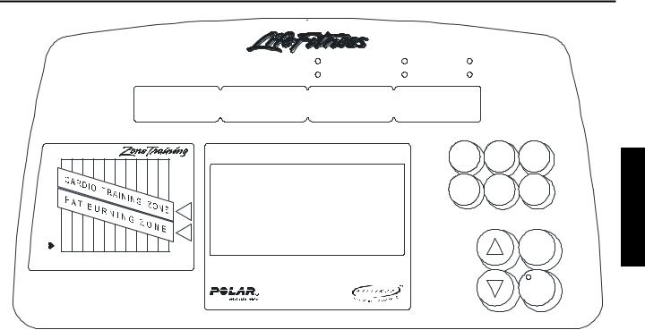
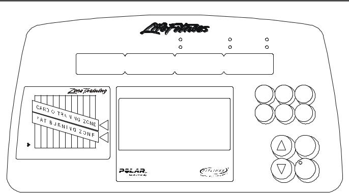
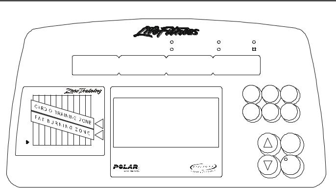
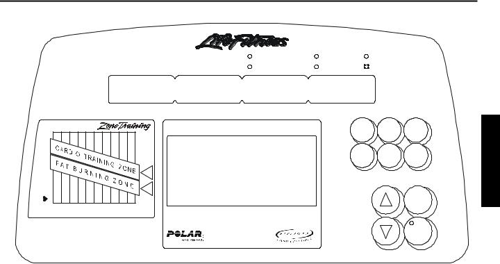
CT8500, CT9100, and CT9500HR Display Consoles
The following three(3) Display Consoles are representative for each model crosstrainer. The following Diagnostic State pages depict a CT9100 Display Console. Regardless of Display Console, the Message Center always provides current Diagnostic Data.
|
|
|
|
|
|
|
|
|
|
|
|
|
Level |
Heart Rate |
Cal/Hour |
|
||
|
|
|
|
|
|
|
|
Time |
|
RPM |
Calories |
Distance |
|
Watts |
|
|||
|
|
|
|
|
|
|
|
|
|
|
|
® |
|
1 |
2 |
|
3 |
Clear |
|
|
|
|
|
|
|
|
|
|
|
|
|
|
|
||||
|
179 |
1 7 0 |
1 6 2 |
153 |
|
|
|
|
|
|
|
|
|
|
Pause |
|||
R A T E |
|
|
145 |
1 3 6 |
1 2 8 |
119 |
111 1 0 2 |
|
|
|
4 |
5 |
|
6 |
Quick |
|||
|
|
|
|
|
|
|
|
8 5 % |
|
|
|
Workout |
||||||
E AR T |
120 |
1 1 7 |
|
|
|
|
|
|
|
|
|
8 0 % |
|
7 |
8 |
|
9 |
Display |
1 1 4 |
111 |
108 |
1 0 5 |
1 0 2 |
|
|
|
|
65% |
|
|
Lock |
||||||
H |
|
|
|
|
|
9 9 |
|
|
|
|
|
|
|
|
|
|||
|
|
|
|
|
|
96 |
93 |
|
|
|
|
0 |
|
|
Start |
|||
|
|
|
|
|
|
|
|
|
6 0 % |
|
|
Aerobics |
|
Reverse |
||||
|
|
|
|
|
|
|
|
|
|
|
|
|
||||||
|
10 |
20 30 40 50 60 70 80 90 100 |
|
|
Mode |
|
Mode |
Start |
||||||||||
|
|
|
|
|
A G E |
|
|
|
|
|
|
Quick Start: |
|
|
|
|
|
|
|
|
|
|
|
|
|
|
|
|
|
|
|
Press ‘Start’ |
|
|
|
|
|
|
|
|
|
|
|
|
|
|
|
|
|
|
Press ‘Quick Workout’ |
|
|
|
|
Entert r |
|
|
Life Fitness USA:1-800-735-3867 |
|
|
|
|
|
|
|
|
|
|
||||||
|
|
Life Fitness Intl.: (+1) 847-288-3300 |
|
|
|
|
|
|
|
|
|
|||||||
|
|
Life Fitness UK: (+44) (0)1353 666017 |
|
|
|
|
|
|
|
|
|
|||||||
|
|
|
CT9500HR (Display Lock Equipped) |
|
||||||||||||||
|
|
|
|
|
|
|
|
|
|
|
|
|
Level |
Heart Rate |
Cal/Hour |
|
||
|
|
|
|
|
|
|
|
Time |
|
RPM |
Calories |
Distance |
|
Watts |
|
|||
|
|
|
|
|
|
|
|
|
¨ |
|
|
® |
|
|
Displayl y |
|
|
|
|
|
|
|
|
|
|
|
|
|
|
|
|
|
|
Clearar |
Pausese |
||
|
179 |
|
|
|
|
|
|
|
|
|
|
|
|
|
Lock |
|
||
|
1 7 0 |
|
|
|
|
|
|
|
|
|
|
|
|
|
|
|
||
E |
1 6 2 |
153 |
145 |
1 3 6 |
|
|
|
|
|
|
|
|
|
|
|
|
||
T |
|
|
|
|
|
1 2 8 |
119 |
111 |
|
|
|
|
|
Aerobicsics Reverse |
Quick |
|||
A |
|
|
|
|
|
|
102 |
|
|
|
|
|||||||
R |
|
|
|
|
|
|
|
|
|
8 5 % |
|
|
|
Mode |
|
Mode |
Workout |
|
|
|
|
|
|
|
|
|
|
|
|
|
|
Mode |
|
|
|||
R T |
120 |
1 1 7 |
1 1 4 |
|
|
|
|
|
|
|
|
8 0 % |
|
|
|
|
|
|
E A |
111 |
108 |
1 0 5 |
1 0 2 |
|
|
|
|
65% |
|
|
|
|
|
|
|||
H |
|
|
|
|
|
9 9 |
96 |
93 |
|
|
|
|
|
|
Start |
|||
|
|
|
|
|
|
|
|
6 0 % |
|
|
|
|
|
|
||||
|
|
|
|
|
|
|
|
|
|
|
|
|
|
|
|
|||
|
10 |
20 30 40 50 60 70 80 90 100 |
|
Quick Start: |
|
|
|
|
|
|||||||||
|
|
|
|
|
A G E |
|
|
|
|
|
|
|
|
|
|
|
||
|
|
|
|
|
|
|
|
|
|
|
|
|
Press ‘Start’ |
|
|
|
|
Entert r |
|
|
|
|
|
|
|
|
|
|
|
|
|
Press ‘Quick Workout’ |
|
|
|
|
|
Life Fitness USA:1-800-735-3867
Life Fitness Intl.: (+1) 847-288-3300
Life Fitness UK: (+44) (0)1353 666017
CT9100
|
|
|
|
|
|
|
|
|
|
|
|
Level |
Heart Rate |
|
Cal/Hour |
|
|
|
|
|
|
|
|
|
Time |
RPM |
Calories |
Distance |
|
Watts |
|
||
|
|
|
|
|
|
|
|
|
|
|
|
|
1 |
2 |
3 |
Clear |
|
179 |
170 |
162 |
|
|
|
|
|
|
|
|
|
Pause |
|||
R AT E |
|
1 5 3 |
145 |
136 |
128 |
119 |
111 |
|
|
|
4 |
5 |
6 |
Quick |
||
|
|
|
|
|
|
|
|
102 |
85% |
|
Workout |
|||||
E A R T |
1 2 0 |
117 |
|
|
|
|
|
|
|
|
80% |
|
7 |
8 |
9 |
|
114 |
111 |
108 |
105 |
102 |
|
|
|
6 5 % |
|
|
||||||
H |
|
|
|
|
|
99 |
96 |
9 3 |
|
|
0 |
|
|
|||
|
|
|
|
|
|
|
|
|
60% |
|
Aerobics |
Reverse |
Start |
|||
|
10 |
20 |
30 40 |
50 |
60 |
70 |
80 90 100 |
|
Quick Start: |
Mode |
Mode |
|
||||
|
|
|
|
|
A G E |
|
|
|
|
|
|
|
|
|
||
|
|
|
|
|
|
|
|
|
|
|
|
Press ‘Start’ |
|
|
|
EnterEnter |
|
|
|
|
|
|
|
|
|
|
|
|
Press ‘Quick Workout’ |
|
|
|
|
Life Fitness USA: 1-800-735-3867
Life Fitness Intl.:(+1) 847-288-3300
Life Fitness UK: (+44) (0)1353 666017
CT9500HR
|
|
Level |
Heart Rate |
Time |
RPM |
Calories |
Distance |
¨®
|
|
|
|
|
|
|
|
|
|
|
|
Display |
Clearar |
PausePa e |
|
179 |
|
|
|
|
|
|
|
|
|
|
Lock |
||
|
170 |
|
|
|
|
|
|
|
|
|
|
|
||
E |
162 153 |
145 |
136 |
|
|
|
|
|
|
|
|
|||
T |
|
|
|
|
|
128 119 |
111 |
|
|
|
|
Quick |
||
A |
|
|
|
|
|
|
102 |
|
|
|
||||
R |
|
|
|
|
|
|
|
|
|
85% |
|
|
Workout |
|
R T |
1 2 0 |
117 |
114 |
|
|
|
|
|
|
|
|
8 0 % |
|
|
A |
111 |
108 |
|
|
|
|
|
|
|
|
|
|||
E |
|
|
|
105 102 |
|
|
|
|
65% |
|
|
|||
H |
|
|
|
|
|
99 |
96 93 |
|
|
Start |
||||
|
|
|
|
|
|
|
|
|
60% |
Quick Start: |
|
|||
|
10 20 30 40 50 60 70 80 |
90100 |
|
|
|
|||||||||
|
|
|
|
|
A G E |
|
|
|
|
|
Press ‘Start’ |
|
|
|
|
|
|
|
|
|
|
|
|
|
|
|
Press ‘Quick Workout’ |
|
|
Entert r
Life Fitness USA: 1-800-735-3867
Life Fitness Intl.:(+1)847-288-3300
Life Fitness UK: (+44) (0)1353 666017
CT8500
Section II
2

Life Fitness Model 8500, 9100, and 9500HR Cross-Trainers
ENTERING DIAGNOSTIC STATES 1-17
To enter the diagnostic mode, proceed as follows:
1.Press down and hold the DOWN ARROW key. While doing this, press the CLEAR (CT9100) or CLEAR/PAUSE (CT9500) key twice within 2.5 seconds. The console will go blank momentarily, but do not release the DOWN ARROW key. As soon as the MESSAGE CENTER displays the word “DIAGNOSTICS,” then release the DOWN ARROW key.
2.Press the ENTER key to scroll through diagnostic states 1-17.
3.Press the UP and DOWN ARROW keys to activate a selection within a diagnostic state.
4.Press the CLEAR key to scroll back to a previous diagnostic state
5.Press the CLEAR key as required to exit out of the diagnostic program.
6.For diagnostic states that have a subdirectory, press the DISPLAY LOCK key to enter.
NOTE: RPM diagnostic mode requires pedaling.
NOTE: Factory defaults are displayed when the LED is illuminated on the ENTER key.
Section II
3
Life Fitness Model 8500, 9100, and 9500HR Cross-Trainers
DIAGNOSTIC STATE 1 - LEDs and KEYPAD TEST
Message
Center
|
|
Level |
Heart Rate |
Cal/Hour |
Time |
RPM |
Calories |
Distance |
Watts |

 248
248
|
|
|
|
|
¨ |
® |
E |
179170162153145 |
|
|
|||
T |
|
|
|
136128 |
|
|
A |
|
|
|
119 |
|
|
R |
|
|
|
|
11110285% |
|
R T |
120117114 |
|
|
80% |
||
A |
|
|
|
|||
E |
|
|
111 |
|
|
|
|
|
|
108 |
|
|
|
H |
|
|
|
105102 99 |
|
65% |
|
|
|
|
|
96 9 3 60% |
|
|
10 |
20 |
30 40 |
50 60 7 0 80 |
90 100 |
|
|
|
|
|
A G E |
|
|
CAUTION: CONSULT A PHYSICIAN BEFORE USING THIS EQUIPMENT. STOP EXERCISING IF YOU FEEL PAIN, FAINT, DIZZY OR SHORT OF BREATH
ATTENTION : CONSULTEZ UN MÉDECIN AVANT D’UTILISER CET APPAREIL. ARRÊTEZVOUS SI VOUS AVEZ DES DOULEURS, SI VOUS VOUS SENTEZ FAIBLE, ÉTOURDI OU À COURT DE SOUFFLE.
Life Fitness USA:1-800-735-3867
Life Fitness Intl.: (+1) 847-288-3300
Displayl |
Clearl |
Pause |
Lock |
|
|
Aerobics |
Reverse |
Quick |
Mode |
Mode |
Workout |
|
Start |
Quick Start: |
|
Press ‘Start’ |
Entert r |
Press ‘Quick Workout’ |
Profile
Window
Initially all LEDs are lit. When pressing the keys listed below, the appropriate character should display across the MESSAGE CENTER.
CROSS-TRAINERS 8500 AND 9100 |
CROSS-TRAINER 9500 |
||
|
|
|
|
KEY MODE DEPRESSED |
CHARACTER DISPLAYED |
KEY MODE DEPRESSED |
CHARACTER DISPLAYED |
Display Lock |
L |
Clear Pause |
- |
Clear |
- |
Quick Workout |
Q |
Pause |
P |
Aerobics Mode |
A |
Aerobics Mode |
A |
Reverse Mode |
R |
Reverse Mode |
R |
Up Arrow |
U |
Quick Workout |
Q |
Down Arrow |
D |
Up Arrow |
U |
Numeric Keys 0-9 |
Numeric Value |
Down Arrow |
D |
Start |
- |
Start |
- |
Enter |
- |
Enter |
- |
|
|
Press the CLEAR key to exit diagnostic mode.
Press the ENTER key to advance to Diagnostic State 2.
4
Life Fitness Model 8500, 9100, and 9500HR Cross-Trainers
DIAGNOSTIC STATE 2 - INDIVIDUAL LED TEST
|
|
Level |
Heart Rate |
Cal/Hour |
Time |
RPM |
Calories |
Distance |
Watts |
|
|
|
|
|
|
|
¨ |
|
® |
|
179170 |
162153145 |
|
|
|
|
|||
E |
|
|
|
|
|
|
|||
T |
|
|
|
|
136128 |
119111 |
|||
A |
|
|
|
|
|
|
|||
R |
|
|
|
|
|
|
|
|
10285% |
R T |
120117114 |
|
|
|
|
|
80% |
||
A |
|
|
|
|
|
|
|||
E |
|
|
111108105 |
102 |
|
|
65% |
||
H |
|
|
|
|
|
99 96 |
9 3 60% |
||
|
|
|
|
|
|
|
|
|
|
|
10 |
20 |
30 40 |
50 |
60 |
70 |
80 |
90 100 |
|
|
|
|
|
AGE |
|
|
|
|
|
CAUTION: CONSULT A PHYSICIAN BEFORE USING THIS EQUIPMENT. |
|||||||||
STOP EXERCISING IF YOU FEEL PAIN, FAINT, DIZZY OR SHORT OF BREATH
ATTENTION : CONSULTEZ UN MÉDECIN AVANT D’UTILISER CET APPAREIL. ARRÊTEZVOUS SI VOUS AVEZ DES DOULEURS, SI VOUS VOUS SENTEZ
FAIBLE, ÉTOURDI OU À COURT DE SOUFFLE.
Life Fitness USA: 1-800-735-3867
Life Fitness Intl.: (+1) 847-288-3300
Display Clearl Pausee
Lock
Aerobics Reverse Quick
Modee Mode Workout
|
Start |
Quick Start: |
|
Press ‘Start’ |
EnterEnter |
Press ‘Quick Workout’ |
In this test, the system scrolls through each LED automatically to test its functionality. Press the CLEAR key to return to Diagnostics State 1.
Press the ENTER key to advance to Diagnostics State 3.
Section II
5
Life Fitness Model 8500, 9100, and 9500HR Cross-Trainers
DIAGNOSTIC STATE 3 - Code Version and RPM, Heart Rate, and LDC Tests
|
|
Level |
Heart Rate |
Cal/Hour |
Time |
RPM |
Calories |
Distance |
Watts |
PX.XX |
0 |
HR |
|
0 |
|
|
|
¨ |
® |
|
179170 |
|
|
|
E |
|
162153 |
|
|
T |
|
145136128 |
|
|
A |
|
119111 |
|
|
R |
|
|
10285% |
|
R T |
120117114 |
|
80% |
|
A |
|
|
||
E |
|
111108105 |
|
65% |
H |
|
102 99 |
96 93 60% |
|
|
|
|
||
|
10 |
20 30 40 50 60 70 80 90 100 |
|
|
|
|
A G E |
|
|
CAUTION: CONSULT A PHYSICIAN BEFORE USING THIS EQUIPMENT. STOP EXERCISING IF YOU FEEL PAIN, FAINT, DIZZY OR SHORT OF BREATH
ATTENTION : CONSULTEZ UN MÉDECIN AVANT D’UTILISER CET APPAREIL.
ARRÊTEZVOUS SI VOUS AVEZ DES DOULEURS, SI VOUS VOUS SENTEZ FAIBLE, ÉTOURDI OU À COURT DE SOUFFLE.
Life Fitness USA: 1-800-735-3867
Life Fitness Intl.: (+1) 847-288-3300
Display |
Clearl r |
Pausese |
Lock |
|
|
Aerobicsi |
Reverse |
Quick |
Modee |
Mode |
Workout |
Start
Quick Start:
Press ‘Start’
Press ‘Quick Workout’ |
EnterEnter |
The items displayed for selection are Code Version, RPM, Heart Rate, and Load Duty Cycle (LDC).
Code Version will be displayed under the TIME segment and will be a four(4) digit number. Press the DISPLAY LOCK key or the “8” key (CT9500) to access software part number xxxx-xxxxx-xxxx. To go back to the original diagnostic screen press the DISPLAY LOCK key or the “8” key (CT9500).
To verify the RPM signal, pedal and observe RPM value.
To verify that the heart rate system is functioning properly, use a polar simulator or a chest strap. If the unit functions correctly the Heart Rate LED will illuminate and a heart rate value will be displayed in the MESSAGE CENTER under the LEVEL and CALORIES segment. Otherwise if heart rate is not detected then the “HR” characters will be displayed and the HEART RATE LED will not be lit.
While pedaling, press the ARROW keys to verify the alternator LOAD DUTY CYCLE. Using the UP ARROW, increase load resistance from 0 to 250. Zero (0) equals a no Load Duty Cycle (LDC) state. 250 equals 100% of LDC. The Load Duty Cycle value will be located under the HEART RATE and DISTANCE segment.
NOTE: Use the PAUSE and QUICK WORKOUT keys to increment and decrement the LDC value by 10% (CT9100/8500 feature). Use 4 and 6 KEYS to increment and decrement LDC value by 10% (CT9500 feature).
Press the CLEAR key to return to Diagnostics State 2.
Press the ENTER key to advance to Diagnostics State 4.
6

Life Fitness Model 8500, 9100, and 9500HR Cross-Trainers
DIAGNOSTIC STATE 3 - Code Version and RPM, Networking, and LDC Tests
(DISPLAY LOCK EQUIPPED MODEL ONLY)
|
|
Level |
Heart Rate |
Cal/Hour |
Time |
RPM |
Calories |
Distance |
Watts |
H E A R T R A T E
179 |
170 |
|
|
|
|
|
|
|
|
® |
1 |
2 |
3 |
Clear |
|
|
|
|
|
|
|
|
|
|
|
|
|
||
|
|
|
|
|
|
|
|
|
|
|
|
|
|
|
|
|
|
|
|
|
|
|
|
|
|
|
|
|
Pause |
|
|
162 |
153 |
145 |
136 |
|
|
|
|
|
4 |
5 |
6 |
|
|
|
|
|
128 |
119 |
|
|
|
Quick |
|||||
|
|
|
|
|
|
111 |
|
|
||||||
|
|
|
|
|
|
|
102 |
85% |
Workout |
|||||
120 |
117 |
|
|
|
|
|
|
|
|
80% |
7 |
8 |
9 |
Display |
|
|
|
|
|
|
|
|
|
||||||
|
|
114 |
111 108 |
105 |
|
|
|
|
|
Lock |
||||
|
|
|
102 |
99 |
|
|
65% |
|
||||||
|
|
|
|
|
|
96 |
93 |
60% |
Aerobics |
0 |
Reverse |
Start |
||
|
|
|
|
|
|
|
|
|
|
|
||||
10 20 30 40 50 60 70 80 90 100 |
|
Mode |
Mode |
|
||||||||||
|
|
|
|
A G E |
|
|
|
|
|
Quick Start: |
|
|
|
|
|
|
|
|
|
|
|
|
|
|
|
Press ‘Start’ |
|
|
EnterEnter |
|
|
|
|
|
|
|
|
|
|
|
Press ‘Quick Workout’ |
|
|
|
Life Fitness USA: 1-800-735-3867
Life Fitness Intl.:(+1) 847-288-3300
Life Fitness UK: (+44) (0)1353 666017
Section II
The items displayed for selection are Code Version, RPM, Networking, and Load Duty Cycle (LDC).
Code Version will be displayed under the TIME segment and will be a four(4) digit number. Press the DISPLAY LOCK key or the “8” key (CT9500) to access software part number xxxx-xxxxx-xxxx. To go back to the original diagnostic screen press the DISPLAY LOCK key or the “8” key (CT9500).
To verify the RPM signal, pedal and observe RPM value.
While pedaling, press the ARROW keys to verify the alternator LOAD DUTY CYCLE. Using the UP ARROW, increase load resistance from 0 to 250. Zero (0) equals a no Load Duty Cycle (LDC) state. 250 equals 100% of LDC. The Load Duty Cycle value will be located under the HEART RATE and DISTANCE segment.
The status of the LIFELINK board and LIFECENTER connection will be displayed in the CALORIES window. The following message will be displayed:
NONE = No LIFELINK board detected
NULL = Board detected but not communicating
ON = Online status with Life Center
OFF = Offline status with Life Center
NOTE: Use the PAUSE and QUICK WORKOUT keys to increment and decrement the LDC value by 10% (CT9100/8500 feature).
Press the CLEAR key to return to Diagnostics State 2.
Press the ENTER key to advance to Diagnostics State 4.
7
8
Life Fitness Model 8500, 9100, and 9500HR Cross-Trainers
DIAGNOSTIC STATE 4 - FIELD/ALTERNATOR-REGULATOR TEST
|
|
Level |
Heart Rate |
Cal/Hour |
Time |
RPM |
Calories |
Distance |
Watts |
FIELD/ALTREG TST
|
|
|
|
|
|
|
|
¨ |
® |
E |
179170 |
|
|
|
|
|
|
|
|
|
162153 |
|
|
|
|
||||
T |
|
|
|
|
145136128 |
|
|
|
|
A |
|
|
|
|
|
119111 |
|
||
R |
|
|
|
|
|
|
|
10285% |
|
R T |
120117114 |
|
|
|
|
80% |
|||
A |
|
|
|
|
|
||||
E |
|
|
|
111108 |
|
|
65% |
||
H |
|
|
|
|
|
105102 |
99 |
|
|
|
|
|
|
|
|
|
96 93 60% |
||
|
|
|
|
|
|
|
|
||
|
10 |
20 |
30 |
40 |
50 |
60 70 |
80 |
90 100 |
|
|
|
|
|
|
A G E |
|
|
|
|
CAUTION: CONSULT A PHYSICIAN BEFORE USING THIS EQUIPMENT. STOP EXERCISING IF YOU FEEL PAIN, FAINT, DIZZY OR SHORT OF BREATH
ATTENTION : CONSULTEZ UN MÉDECIN AVANT D’UTILISER CET APPAREIL. ARRÊTEZVOUS SI VOUS AVEZ DES DOULEURS, SI VOUS VOUS SENTEZ FAIBLE, ÉTOURDI OU À COURT DE SOUFFLE.
Life Fitness USA: 1-800-735-3867
Life Fitness Intl.: (+1) 847-288-3300
Displayl |
Clear |
Pausese |
Lock |
|
|
Aerobics |
Reverse |
Quick |
Mode |
Mode |
Workout |
Start
Quick Start:
Press ‘Start’
Press ‘Quick Workout’ |
EnterEnter |
Prior to enter the test modes, set the field load duty in diagnostics state 3 to 50. Press the Display Lock key, or the number 2 key for CT9500 only, once to access Field Test. Use the UP/DOWN ARROW toggle the field voltage ON and OFF. This will verify the operation of the alternator and cable connections. The resistance should increase as the field test is turned on.
Press the Display Lock key, or the number 2 key for CT9500 only, again to access the Alternator/Regulator Test. Use the UP/DOWN ARROW key to toggle voltage ON/OFF. This will verify that the power control board is regulating the voltage properly and the load resistance should slightly decrease as the alternator/regulator is turned on.
Press the CLEAR key to return to Diagnostics State 3.
Press the ENTER key to advance to Diagnostics State 5.
9
Life Fitness Model 8500, 9100, and 9500HR Cross-Trainers
DIAGNOSTIC STATE 5 - PROGRAM VERSION AND NETWORKING TEST
|
|
Level |
Heart Rate |
Cal/Hour |
Time |
RPM |
Calories |
Distance |
Watts |
PX.XX |
PX.XX |
|
NONE |
|
|
|
|
|
|
|
|
|
¨ |
® |
E |
179170 |
|
|
|
|
|
|
|
|
|
162153 |
|
|
|
|
||||
T |
|
|
|
|
145136128 |
|
|
|
|
A |
|
|
|
|
|
119111 |
|
||
R |
|
|
|
|
|
|
|
10285% |
|
R T |
120117114 |
|
|
|
|
80% |
|||
A |
|
|
|
|
|
||||
E |
|
|
|
111108 |
|
|
65% |
||
H |
|
|
|
|
|
105102 |
99 |
|
|
|
|
|
|
|
|
|
96 93 60% |
||
|
|
|
|
|
|
|
|
||
|
10 |
20 |
30 |
40 |
50 |
60 70 |
80 |
90 100 |
|
|
|
|
|
|
A G E |
|
|
|
|
CAUTION: CONSULT A PHYSICIAN BEFORE USING THIS EQUIPMENT. STOP EXERCISING IF YOU FEEL PAIN, FAINT, DIZZY OR SHORT OF BREATH
ATTENTION : CONSULTEZ UN MÉDECIN AVANT D’UTILISER CET APPAREIL. ARRÊTEZVOUS SI VOUS AVEZ DES DOULEURS, SI VOUS VOUS SENTEZ FAIBLE, ÉTOURDI OU À COURT DE SOUFFLE.
Life Fitness USA: 1-800-735-3867
Life Fitness Intl.: (+1) 847-288-3300
Displayl |
Clear |
Pausese |
Lock |
|
|
Aerobics |
Reverse |
Quick |
Mode |
Mode |
Workout |
Start
Quick Start:
Press ‘Start’
Press ‘Quick Workout’ |
EnterEnter |
The PROGRAM VERSION NUMBER for 68HC05 micro controller code version will be displayed in the elapsed time window (e.g. P_. _0).
The PROGRAM VERSION NUMBER for HEART RATE DSP Board will be displayed in the speed window (eg. P_. _0).
The status of the LIFELINK board and LIFECENTER connection will be displayed in the CALORIES window. The following message will be displayed:
NONE = No LIFELINK board detected
NULL = Board detected but not communicating
ON = Online status with Life Center
OFF = Offline status with Life Center
Press the CLEAR key to return to Diagnostics State 4.
Press the ENTER key to advance to Diagnostics State 6.
Section II
10

Life Fitness Model 8500, 9100, and 9500HR Cross-Trainers
DIAGNOSTIC STATE 5 – LIFEPULSE TEST
(DISPLAY LOCK EQUIPPED MODEL ONLY)
|
|
|
|
|
|
|
|
|
|
|
|
|
Level |
Heart Rate |
|
Cal/Hour |
|
|
|
|
|
|
|
|
|
Time |
|
RPM |
Calories |
Distance |
|
Watts |
|
||
|
|
|
|
|
|
|
|
|
|
|
|
® |
|
1 |
2 |
3 |
Clear |
|
|
|
|
|
|
|
|
|
|
|
|
|
|
||||
|
179 170 |
|
|
|
|
|
|
|
|
|
|
|
Pause |
||||
R A T E |
162 |
153 |
|
|
|
|
|
|
|
|
|
|
|||||
|
|
145 |
136 |
128 |
|
|
|
|
|
|
4 |
5 |
6 |
Quick |
|||
|
|
|
|
|
119 |
111 102 |
|
|
|
||||||||
|
|
|
|
|
|
|
85% |
|
|
Workout |
|||||||
E A R T |
120 |
117 |
|
|
|
|
|
|
|
|
|
80% |
|
7 |
8 |
9 |
Display |
|
|
|
|
|
|
|
|
|
|
|
|||||||
|
114 |
111 |
108 |
105 |
102 |
|
|
|
|
65% |
|
Lock |
|||||
H |
|
|
|
|
|
99 |
|
|
|
|
|
|
|
|
|||
|
|
|
|
|
|
96 |
93 |
|
|
|
|
0 |
|
|
|||
|
|
|
|
|
|
|
|
|
60% |
|
|
Aerobics |
Reverse |
Start |
|||
|
|
|
|
|
|
|
|
|
|
|
|
||||||
|
|
|
|
|
|
|
|
|
|
|
|
|
|||||
|
10 20 30 40 50 60 70 80 90100 |
|
|
Quick Start: |
Mode |
Mode |
|
||||||||||
|
|
|
|
|
A G E |
|
|
|
|
|
|
|
|
|
|
||
Press ‘Start’
Press ‘Quick Workout’ |
Entert r |
Life Fitness USA: 1-800-735-3867
Life Fitness Intl.:(+1) 847-288-3300
Life Fitness UK: (+44) (0)1353 666017
Upon initial entry to this test, a message concerning the configuration of the lifepulse system being On or Off. This test will allow the user to test the lifepulse heart rate system.
Following this message, the lifepulse system can be manually tested. A heart will be in the profile window.
The system will show when the user has placed their hands on the lifepulse sensors. When the left sensor detects hands on condition, a ‘L’ will be placed in the profile window with the heart. When the right sensor detects hands on condition, a ‘R’ will be placed in the profile window with the heart.
A timer will start counting from the time when a both left and right hands on condition occurs to when the lifepulse system can reliable give the user their heart rate. This timer will stop when the heart rate is given.
The gain value of the heart rate signal is shown. The confidence level of the heart rate value is displayed. The value ranges from 0 to 9. A value of 9 is considered to be high confidence. A value of 0 is considered to be low confidence.
Press the CLEAR key to return to Diagnostics State 4.
Press the ENTER key to advance to Diagnostics State 6.
11

Life Fitness Model 8500, 9100, and 9500HR Cross-Trainers
DIAGNOSTIC STATE 6 - MAXIMUM WORKOUT DURATION
|
|
Level |
Heart Rate |
Cal/Hour |
Time |
RPM |
Calories |
Distance |
Watts |
MAX DURATION 60
|
|
|
|
|
¨ |
® |
|
179170 |
|
|
|
|
|
E |
|
162153145 |
|
|
|
|
T |
|
|
136128 |
|
|
|
A |
|
|
119 |
|
||
|
|
|
|
111 |
||
R |
|
|
|
|
|
10285% |
R T |
120117114 |
|
|
|
80% |
|
A |
|
|
|
|
||
E |
|
111108 |
|
|
|
|
H |
|
|
105102 |
99 96 |
65% |
|
|
|
|
|
93 60% |
||
|
|
|
|
|
|
|
|
10 |
20 30 40 |
50 60 70 80 |
90 100 |
||
|
|
|
A G E |
|
|
|
CAUTION: CONSULT A PHYSICIAN BEFORE USING THIS EQUIPMENT. STOP EXERCISING IF YOU FEEL PAIN, FAINT, DIZZY OR SHORT OF BREATH
ATTENTION : CONSULTEZ UN MÉDECIN AVANT D’UTILISER CET APPAREIL. ARRÊTEZVOUS SI VOUS AVEZ DES DOULEURS, SI VOUS VOUS SENTEZ
FAIBLE, ÉTOURDI OU À COURT DE SOUFFLE.
Life Fitness USA: 1-800-735-3867
Life Fitness Intl.: (+1) 847-288-3300
Display |
Clearl |
Pausee |
Lock |
|
|
Aerobicsi s Reverse Quick
Mode Mode Workout
Start
Quick Start:
Press ‘Start’
Press ‘Quick Workout’ |
Entert r |
Section II
Maximum program duration can be adjusted from a range between 60-99 minutes. Press the DOWN ARROW to decrease values in decrements of 1 minute. Press the UP ARROW key to increase values in increments of 1 minute.
The LED on the ENTER key will illuminate when the value is set to the default of 60 minutes. This value is stored in EEPROM and is stored when the cross-trainer is not in use.
Press the CLEAR key to return to Diagnostics State 5.
Press the ENTER key to advance to Diagnostics State 7.
12

Life Fitness Model 8500, 9100, and 9500HR Cross-Trainers
DIAGNOSTIC STATE 7 - TELEMETRY ON/OFF
|
|
Level |
Heart Rate |
Cal/Hour |
Time |
RPM |
Calories |
Distance |
Watts |
TELEMETRY ON
|
|
|
¨ |
® |
|
179170 |
|
|
|
E |
|
162153145 |
|
|
T |
|
136128 |
|
|
A |
|
119111 |
|
|
R |
|
|
10285% |
|
R T |
120117114 |
|
80% |
|
A |
|
|
||
E |
|
111108 |
|
|
H |
|
10510299 |
|
65% |
|
|
|
96 93 60% |
|
|
10 |
20 30 40 50 60 70 80 |
90 100 |
|
|
|
A G E |
|
|
CAUTION: CONSULT A PHYSICIAN BEFORE USING THIS EQUIPMENT. STOP EXERCISING IF YOU FEEL PAIN, FAINT, DIZZY OR SHORT OF BREATH
ATTENTION : CONSULTEZ UN MÉDECIN AVANT D’UTILISER CET APPAREIL.
ARRÊTEZVOUS SI VOUS AVEZ DES DOULEURS, SI VOUS VOUS SENTEZ FAIBLE, ÉTOURDI OU À COURT DE SOUFFLE.
Life Fitness USA: 1-800-735-3867
Life Fitness Intl.: (+1) 847-288-3300
Display |
Clearr |
PauseP e |
Lock |
|
|
Aerobicsi s |
Reverse |
Quick |
Mode |
Mode |
Workout |
Start
Quick Start:
Press ‘Start’
Press ‘Quick Workout’ |
Enternter |
The default is TELEMETRY ON (CT91/95) TELEMETRY OFF (CT85). Press the DOWN ARROW to turn OFF telemetry and the UP ARROW to turn it back ON. A heart shape illuminates in the program profile window.
The ENTER key LED illuminates to indicate when TELEMETRY ON. This value is stored in EEROM while the crosstrainer is not in use.
Press the CLEAR key to return to Diagnostic State 6.
Press the ENTER key to advance to Diagnostic State 8.
13
 Loading...