


Life Fitness Model 9500HR Treadmills
How to…Install the Support Plate on Damaged Frame Cross-Member/Bracket
Tools required: Hex Key Wrench Set, Socket Set, C-Clamps, Phillips Screwdriver |
GK26-00002-0063 |
NOTE: STEPS 1-12 cover Belt, Deck, and Wax Bag Removal.
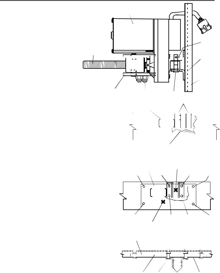
1.Turn the unit power OFF, then unplug the POWER CORD at the electrical outlet.
2.Remove the front and rear FRAME CAPS on the right side of the unit.
3.Remove the right HANDRAIL FOOT COVER.
4. Remove the mounting bolts securing right HANDRAIL to the frame.
5. Before loosening the STRIDING BELT, mark the location of the
BELT TENSIONING BOLTS or record the number of turns for proper belt re-tensioning.
6. Loosen the STRIDING BELT by turning the BELT TENSIONING BOLTS counterclockwise.
7. Carefully tilt the unit on its left side (user's left) and remove the rear ROLLER GUARD.
8.Cover the end of the stationary
leg to protect the striding belt |
|
Frame |
|
Wax Bag |
|
during removal. |
|
Tray |
|
|
|
|
|
|
|
||
|
|
|
|
|
|
9. Remove the striding belt.
10. Carefully tilt the unit back to its upright, normal operating position.
11. Remove the DECK SCREWS and
DECK.
12. Pinch-off the wax hose and |
|
remove the WAX COVER, BAG, |
Cover |
and TRAY. |
Washer (4) |
|
|
|
Mounting Bolts (4) |
Life Fitness Model 9500HR Treadmills
How to…Install the Support Plate on Damaged Frame Cross-Member/Bracket
NOTE: STEPS 13-16 cover LIFT ACTUATOR REMOVAL
Actuator Motor
and ASSESSEMENT OF DAMAGE to THE FRAME CROSS-MEMBER.
13.Unplug the LIFT ACTUATOR from the WIRE HARNESS.
14.Remove the upper nut, bolt, and washer securing the ACTUATOR NUT BRACKETS together. Loosen the lower
nut, bolt, and washer and lift out the actuator nut past the bracket pins.
With the lift motor out, DO NOT turn
the adjusting screw. This will alter the incline and decline setting.
15.At the non-threaded end of the LIFT ACTUATOR, remove the HAIRPIN CLIP and CLEVIS PIN and lift out the actuator motor.
Pin 


Actuator
Nut
Actuator |
|
|
Nut Bracket |
Pin |
Nut, Bolt, |
|
||
|
|
Washer(2) |
 Hair Pin
Clip


 Bracket
(Welded to
Cross-Member)
Cross-Member (Welded to Bracket)
Clevis
Pin
16.Assess the damage to the cross-member and welded bracket. Make repairs as necessary to restore back to original location.
NOTE: STEPS 17-20 cover FRAME CROSS-MEMBER repairs and installation of the SUPPORT PLATE.
17.Once the cross-member is restored, position the pre-drilled SUPPORT PLATE on the inside channel of the CROSSMEMBER and use as a template in drilling eight holes in the cross-member. Secure the support plate into position with two C-Clamps at the locations shown. Make sure to match-up the square hole in the plate with the square
hole in the cross-member.
18.Using the 9/32" and 11/32" drill bits provided, drill holes
in the cross-member in the sequence illustrated. Use the 9/32" drill bit for bracket holes (1,2,3,4) and the 11/32" drill bit on the outer ends of the support plate (5,6,7,8).
19.After the first hole in the sequence is drilled, tighten the plate with a bolt, washer, and nut to secure the crossmember for proper hole alignment. Drill the next hole in sequence and, when completed, fasten with bolt, washer and nut and tighten. Complete drilling the remaining holes, and install bolt, washer, nut and tighten.
20.Install the lift motor in reverse order of removal. If the lift actuator screw was turned, refer to STEPS 21-24.
Square |
|
|
Bracket |
||||
|
|
|
|
|
|
|
|
Hole |
|
|
|
|
|
|
|
|
|
|
|
|
|
|
|
|
|
|
|
|
|
|
|
|
|
|
|
|
|
|
|
|
|
|
|
|
|
|
|
|
|
|
|
|
|
|
|
|
|
|
|
|
|
|
|
|
|
|
|
|
|
|
|
Cross-Member (Cracked and Bent)
Support Plate |
|
|
|
clamped |
|
Clamp |
|
into position |
Location |
|
|
#5 (11/32”) |
#3 (9/32”) |
#4 (9/32”) |
#7 (11/32”) |
|
|
|
|
|
|
|
|
|
|
|
|
|
|
|
|
|
|
|
|
|
|
|
|
|
|
|
|
|
|
|
|
|
|
|
|
|
|
|
|
|
|
|
|
|
|
|
|
|
|
|
|
|
|
|
|
|
|
|
|
|
|
|
|
|
|
|
|
|
|
|
|
|
|
|
|
|
|
|
|
|
|
|
|
|
|
|
|
|
|
|
|
|
#6 (11/32”) |
|
|
#2 (9/32”) |
#1 (9/32”) |
|
#8 (11/32”) |
||||||||||||||||||||||||
|
|
|
|
|
|
|
Clamp |
|
|
|
|
|
|
|
|
|||||||||||||||
|
|
|
|
|
|
|
Location |
|
|
|
|
|
|
|
|
|||||||||||||||
|
Support |
|
Flat |
|
|
|
Hex |
|
|
|
||||||||||||||||||||
|
Plate |
|
Washer |
|
|
|
Nut |
|
|
|
||||||||||||||||||||
|
|
|
|
|
|
|
|
|
|
|
|
|
|
|
|
|
|
|
|
|
|
|
|
|
|
|
|
|
|
|
|
|
|
|
|
|
|
|
|
|
|
|
|
|
|
|
|
|
|
|
|
|
|
|
|
|
|
|
|
|
|
|
|
|
|
|
|
|
|
|
|
|
|
|
|
|
|
|
|
|
|
|
|
|
|
|
|
|
|
|
|
|
|
|
|
|
|
|
|
|
|
|
|
|
|
|
|
|
|
|
|
|
|
|
|
|
|
|
|
|
|
|
|
|
|
|
|
|
|
|
|
|
|
|
|
|
|
|
|
|
|
|
|
|
|
|
|
|
|
|
|
|
|
|
|
|
|
|
|
|
|
|
|
|
|
|
|
|
|
|
|
|
|
|
|
|
|
|
|
|
|
|
|
|
|
|
|
|
|
|
|
|
|
|
|
|
|
|
|
|
|
|
|
|
|
|
|
|
|
|
|
|
|
|
|
|
|
|
|
|
|
|
|
|
|
|
|
|
|
|
|
|
|
|
|
|
|
|
|
|
|
|
|
|
|
|
|
|
|
|
|
|
|
|
|
|
|
|
|
|
|
|
|
|
|
|
|
|
|
|
|
|
|
|
|
|
|
|
|
|
|
|
|
|
|
|
|
|
|
|
|
|
|
|
|
|
|
|
|
|
|
|
|
|
|
|
|
|
|
Square Bolt |
Bracket |
Cross-Member |
Hole |
|
|
 Loading...