


DELUXE HIGH WALL MINI SPLIT INSTALLATION INSTRUCTIONS
IMPORTANT! |
|
Please read this instruction |
installing the product. |
This air conditioning system meets strict it is an important part of your job to install
. As the installer or service person, safely and efficiently.
WARNING
•Installation or repairs made by unqualified persons can result in hazards to you and others.
Installation MUST conform with local building codes or, in the absence of local codes, with the National Electrical Code NFPA 70/ANSI C1-1993 or current edition and Canadian Electrical Code Part1 CSA C.22.1.
•The information contained in the manual is intended for use by a qualified service technician familiar with safety procedures and equipped with the proper tools and test instruments.
•Failure to carefully read and follow all instructions in this manual can result in equipment malfunction, property damage, personal injury and/or death.
CAUTION: Improper installation, |
can void the warranty. |
The weight of the condensing |
handling procedures when lifting |
or moving to avoid personal |
with sharp or pointed edges. |
Safety Precautions |
|
• Always wear safety eye wear |
equipment. |
• Never assume electrical |
with meter and equipment. |
• Keep hands out of fan areas |
equipment. |
• R-22 causes frostbite burns. |
|
• R-22 is toxic when burned. |
|
NOTE TO INSTALLING DEALER: |
are to be given to the owner |
or |
indoor Furnace/Air Handler Unit. |
Special warnings
When wiring:
Electrical shock can cause severe personal injury or death. Only a qualified, experienced electrician should attempt to wire this system.
•Do not supply power to the unit until all wiring and tubing are completed or reconnected and checked.
•Highly dangerous electrical voltages are used in this system. Carefully refer to the wiring diagram and these instructions when wiring. Improper connections and inadequate grounding can cause accidental injury or death.
•Ground the unit following local electrical codes.
•Connect all wiring tightly. Loose wiring may cause overheating at connection points and a possible fire hazard.
When transporting:
Be careful when picking up and moving the indoor and outdoor units. Get a partner to help, and bend your knees when lifting to reduce strain on your back. Sharp edges or thin aluminum fins on the air conditioner can cut your finger.
When installing...
... in a wall: Make sure the wall is strong enough to hold the unit's weight.
It may be necessary to construct a strong wood or metal frame to provide added support.
... in a room: Properly insulate any tubing run inside a room to prevent "sweating" that can cause dripping and water damage to wall and floors.
... in moist or uneven locatinons: Use a raised concrete pad or concrete blocks provide a solid, level foundation for the outdoor unit. This prevents water damage and abnormal vibration.
... in an area with high winds: Securely anchor the outdoor unit down with bolts and a metal frame. Provide a suitable air baffle.
... in a snowy area(for Heat Pump Model): Install the outdoor unit on a raised platform that is higher than drifting snow. Provide snow vents.
When connecting refrigerant tubing
•Keep all tubing runs as short as possible.
•Use the flare method for connecting tubing.
•Check carefully for leaks before starting the test run.
When servicing
•Turn the power OFF at the main power box(mains) before opening the unit to check or repair electrical parts and wiring.
•Keep your fingers and clothing away from any moving parts.
•Clean up the site after you finish, remembering to check that no metal scraps or bits of wiring have been left inside the unit being serviced.
P/NO:3828A30087B
OUT-LINE OF INSTALLATION
Installation works |
|
Installation Parts |
|
Required Tools |
|
|
|
|
|
1.Installation Parts Providided
2.Installation of indoor, Outdoor Unit
1) Selection of the best location |
.....3 |
• Installation Plate |
• Level |
2) Indoor unit Installation ............. |
4 |
• Four Type "A" screws |
• Screw driver |
|
|
• Connecting cable |
• Electric drill |
|
|
|
• Hole core drill; ø70mm(2.76") |
3. Piping and drainage of indoor unit
1) |
Preparation of Pipings |
.............5 |
• Pipes: Gas side....... |
1/2"(9K, |
12K) |
|
2) |
Connection of Pipings |
6~7 |
........ |
5/8"(18K, 24K) |
||
Liquid side |
1/4"(9K, |
12K) |
||||
3) |
For the left Pipings |
8~10 |
||||
|
|
|
||||
.....3/8"(18K, 24K)
• Insulated drain hose
• Insulation materials
•Flaring Tools set
•Specified Torque Wrenches Liquid side - 1.8kg.m(13ft.lbs):9K, 12K
4.0kg.m(28.9ft.lbs):18K, 24K Gas side - 5.5kg.m(39.8ft.lbs):9K, 12K
6.6kg.m(47.7ft.lbs):18K, 24K
Spanner |
.......................Half union |
4. Connecting Pipings and the cable to Outdoor unit
1) |
Connection of Pipings ............ |
11 |
• Additional Drain hose |
• Specified Torque Wrenches |
|
2) |
Connection of the cable |
11~12 |
(Inner Dia |
................ø16mm(5/8") |
Liquid side - 1.8kg.m(13ft.lbs):9K, 12K |
|
|
4.0kg.m(28.9ft.lbs):18K, 24K |
|||
|
|
|
|
|
|
|
|
|
|
|
Gas side - 5.5kg.m(39.8ft.lbs):9K, 12K |
|
|
|
|
|
6.6kg.m(47.7ft.lbs):18K, 24K |
5. |
Checking the Drainage and Connecting the cable to Indoor unit |
|||||
1) |
Checking the Drainage |
.........13 |
|
• Screw driver |
||
2) |
Connecting of the cable ......... |
14 |
|
|
||
3) Forming the pipings ............... |
15 |
|
|
|||
|
|
|
|
• A glass of water |
|
|
6. |
Air Purging |
|
|
|
|
|
1) |
Air Purging ...................... |
|
16~17 |
|
• Hexagonal Wrench (4mm; 5/32") |
|
|
|
|
|
|
|
• Gas-leak Detector |
7. |
Test running |
................ |
|
|
||
|
18 |
|
|
|||
|
|
|
|
• Two type "B" screws |
• Owner's Manual |
|
|
|
|
|
|
|
• Thermometer |
8. |
Installation Instruction Templates |
........................................................................................... |
||||
|
19 |
|||||
2
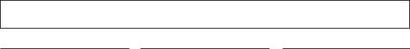
1. Installation Parts Provided
1. |
Type "A" screw |
3. |
Type "B" screw |
|
|
||
2. |
Installation Plate |
4. |
Holder Remote-Controller |
|
|
2.Installation of Indoor, Outdoor unit
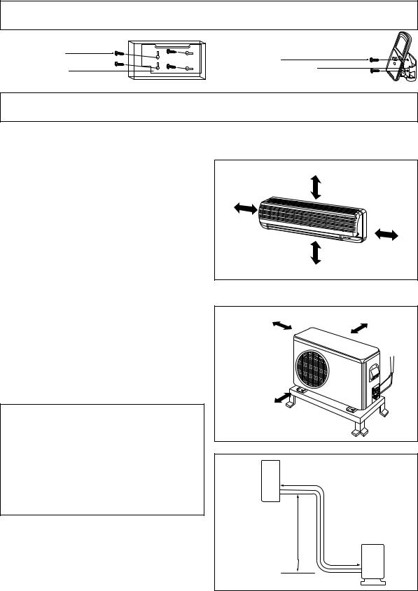
1)Selection of the best location
1. Indoor unit.
•There should not be any heat source or steam near the unit.
•There should not be any obstacles to prevent the air circulation.
•A place where air circulation in the room will be good.
•A place where drainage can be easily obtained.
•A place where noise prevention is taken into consideration.
•Do not install the unit near the door way.
•Ensure the spaces indicated by arrows from the wall, ceiling, fence, or other obstacles.
More than |
More than 5 cm(2") |
|
5 cm(2") |
||
|
||
|
More than |
|
|
5 cm(2") |
|
More than eye level |
|
2.Outdoor unit.
•If an awning is built over the unit to prevent direct sunlight or rain exposure, be careful that heat radiation from the condenser is not restricted.
•There should not be any animals or plants which could be affected by hot air discharged.
•Ensure the spaces indicated by arrows from the wall, ceiling, fence, or other obstacles.
Roof Top Installations
If it is necessary to install units on a roof structure, be sure to elevate and level the units. Ensure the roof structure and anchoring method are adequate for unit location. Consult local codes regarding rooftop mounting.
NOTE: When condensing unit is to be installed on a bonded guaranted roof, a release must be obtained from the building owner to free the installer from all liabilities.
3.Piping length and the elevation
MODEL |
Pipe Size |
Max. |
Max. |
||
(Cooling Capa.) |
|
|
length |
Elevation |
|
GAS |
LIQUID |
||||
|
A |
B |
|||
|
|
|
|
|
|
9K, 12K |
1/2" |
1/4" |
15m(50ft) |
8m(26ft) |
|
|
|
|
|
|
|
18K, 24K |
5/8" |
3/8" |
15m(50ft) |
8m(26ft) |
|
|
|
|
|
|
|
More than 10 cm(4") More than 10 cm(4")
More than 70 cm(28")
Indoor unit
B A
Outdoor unit
3

2) Indoor Unit Installation
The mounting wall should be strong and solid enough to protect it from the vibration.
1.Mount the installation plate on the wall with four Type "A" screws.
(if mounting the unit on the concrete wall, consider using anchor bolts.)
•Always mount the Installation Plate horizontally by aligning the marking-off line by means of the thread and a level.
|
Installation Plate |
Type "A" screw |
marking-off line |
|
Thread |
|
Weight |
2.Drill the piping hole with 70mm(2.75") dia. holecore drill.
• See templates in the back of this
manual(page |
location |
relative to |
. |
• Drill the |
right or the |
left and the |
slanted |
to the outdoor |
|
 WARNING
Avoid areas where electrical wiring, conduits or gas lines are located. Accidentally cutting a live wire or gas line can cause death or injury.
The lower left and right side of Installation Plate
Left rear piping |
Right rear piping |
|
||
|
|
1" |
2" |
|
|
|
(25mm) |
(51mm) |
|
1.8" |
(46mm) |
1.9" |
(48mm) |
Hole center |
|
||||
9K, 12K, 18K, 24K |
9K,12K |
18K, 24K |
||
|
ø2.75"(70mm) |
|
|
|
|
|
Installation plate |
|
|
|
|
WALL |
|
|
|
INDOOR |
OUTDOOR |
|
|
5-7mm |
3").2~0 .(0 |
4
3. Piping and Drainage of Indoor Unit
1) Preparation of pipings
1.Cut the pipes and the cable.
•Use the pipes purchased locally.
•Measure the distance between the indoor and the outdoor unit.
•Cut the pipes a little longer than measured distance.
•Cut the cable 1.5m(5.0 ft) longer than the length of the pipe.
Pipe cutter
Slanted Rough
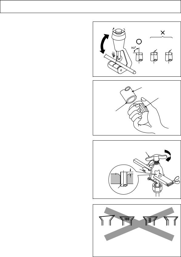
2.Remove burrs.
•Remove burrs from cut edges of pipes.
•Turn the pipe end toward down to avoid the metal powder entering the pipe.
Caution:
If burrs are not removed, they may cause a gas leakage.
3.Flaring the pipes.
•Insert the flare nuts, mounted on the connection ports of both indoor and outdoor unit, onto the copper pipes. Some gas may leak, when the flare nuts are removed from the indoor unit, as some gas is charged to prevent the inside of the pipe from rusting.
•Fit the copper pipe end into the Bar of flare tool about 0.5~1.0mm higher. (See illustration)
•Make a flare at the end of copper pipe with a flare tool*.
*Use "RIDGID" or equivalent.
4.Tape the flaring portion to protect it from the dust or damages.
Pipe
Reamer
Point down
"A"; ø6.35mm (1/4") ¡ 0.5mm ø9.52mm (3/8") ¡ 0.5 mm ø12.7mm (1/2") ¡ 0.5 mm ø15.88mm (5/8") ¡ 1.0mm
Bar Ä
Copper pipe
Handle
 Yoke
Yoke

 Cone
Cone
= Improper flaring =
Inclined |
Surface |
Cracked |
Uneven |
|
damaged |
|
thickness |
When properly flared, the internal surface of the flare will evenly shine and be of even thickness. After the flare part comes into contact with the connectors, carefully check the flare finish.
5

2) Connection of Pipings
1.Remove the indoor tubing with Drain hose from the hole
•Remove tubing holder and pull the tubing out of the chassis.
2.Replace the tubing holder into original position.
•Recommended SPEC. of the additional Drain Hose.
Joint Part |
The material of Drain hose |
||
Inner size |
Material |
||
|
|||
MAX. |
soft PVC |
Soft PVC hose |
|
ø16mm(5/8") |
(It must be surrounded with an Insulation Material*) |
||
|
|
|
|
*Foamed Polyethylene or equivalent is recommended.
CAUTION: The unit's drain hose and additional drain hose must be sealed up by adhesive or tape.
Tubing holder
To remove the holder, |
|
press the bottom of |
|
chassis near the holder |
¤ŁPull |
upward and pull the tab |
|
out of its hole. |
¤ Press |
For right rear piping
3.Route the tubing and the drain hose straight backwards.
4.Insert the connecting cable into the indoor unit through the piping hole.
•Do not connect the cable to the indoor unit.
•Make a small loop with the cable for easy connection later.
5.Tape the tubing, drain hose and the connecting cable. Be sure that drain hose locates at the lowest side of the bundle. Locating at the upper side can be a reason that drain water overflows drain pan inside the unit.
|
Gas side piping |
|
Connecting |
Liquid side piping |
|
cable |
||
Drain hose |
||
|
NOTE |
|
|
|
If the drain |
room, |
|
|
insulate the |
|
|
|
material* so |
|
|
|
"sweating"(condensation) |
not damage |
Taping |
|
furniture or |
|
||
|
Indoor/Outdoor |
||
* Foamed |
is |
||
Connecting cable |
|||
recommended. |
|
|
6
 Loading...